

Novatel ANT-26C1GA-TBW-N, ANT-26C1GA-TBW-AN User Manual
ANT-26C1GA-TBW-N and ANT-26C1GA-TBW-AN
Antennas
The compact, lightweight ANT-26C1GATBW-N and ANT-26C1GA-TBW-AN
model antennas are designed for use in
any mobile application.
The ANT-26C1GA-TBW-N and ANT26C1GA-TBW-AN are active GPS
antennas designed to work at the L1
frequency (1575.42 ±12 MHz). These
antennas include the following features:
• Lightning and rain protection
• Universal single hole mounting with a threaded
connector and nut
• Internal 33 dB amplifier
• Designed for long cable remote installation
• Band pass filtering
• DC bias provided through the coaxial connector
NovAtel offers optional coaxial cables of various lengths and
models for interconnecting between the ANT-26C1GA-TBW-N
and ANT-26C1GA-TBW-AN, and our receivers.
ADDITIONAL EQUIPMENT REQUIRED
• A device with an antenna input port that both receives the RF
signal and provides 2.5 to 24.0 VDC to the antenna is required
to set up the ANT-26C1GA-TBW-N and ANT-26C1GA-TBWAN. (NovAtel GPS receivers provide the necessary power
through their antenna RF connectors.)
• Coaxial cable with a male TNC connector
INSTALLING THE ANTENNA
Both the input DC power and the output RF signal flow over a
single coaxial cable that is connected to the unit's TNC female
connector.
The antenna can be attached to a surface by means of a single
pre-drilled mounting hole.
Install the antenna as follows:
1. Pre-drill the connector hole on the surface, see the
Mechanical Drawings section of this guide for details on the
connector size.
2. Put the antenna connector through the pre-drilled mounting
hole of the surface.
3. Fasten the antenna tightly to the surface using the mounting
hex nut and its lock washer.
Ref. # Description Ref.# Description
1 Antenna 4 Pre-drilled mounting hole
2 Mounting surface 5 Mounting hex nut and lock washer
3 TNC connector (24mm nut in the case of the
ANT-26C1GA-TBW-AN)
4. Remove the dust cap from the antenna’s TNC connector.
5. Attach the male TNC connector of the coaxial cable to the
antenna’s TNC connector (see the top graphic on the next
panel).
Ref. # Description Ref. # Description
1 Antenna in place 3 TNC connector
2 Surface 4 Coaxial cable
6. Attach the other end of the coaxial cable to the antenna input
port of the receiving device, which must provide power as
detailed in the SPECIFICATIONS section of this guide. All
NovAtel GPS receivers provide the necessary power
through their antenna RF connectors.
The above shows an example of where the ANT-26C1GATBW-N or ANT-26C1GA-TBW-AN antenna may be placed
on a vehicle (not to scale).
ANTENNA CARE
The ANT-26C1GA-TBW-N and ANT-26C1GA-TBW-AN are
designed to withstand the elements, including rain, snow, and
dust. However, to ensure your antenna performs optimally, keep
the radome clean and brush off any ice and snow. In addition,
ensure the TNC connector remains clean and dry and replace
the dust cap when a cable is not connected.
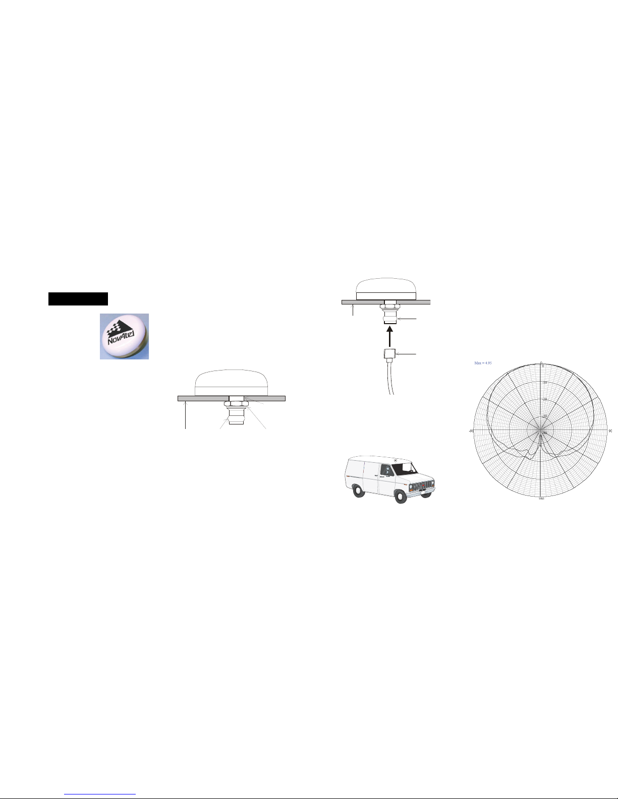
L1 ELEVATION GAIN PATTERN
USER GUIDE
2 3 5
1
4
3
2
4
1
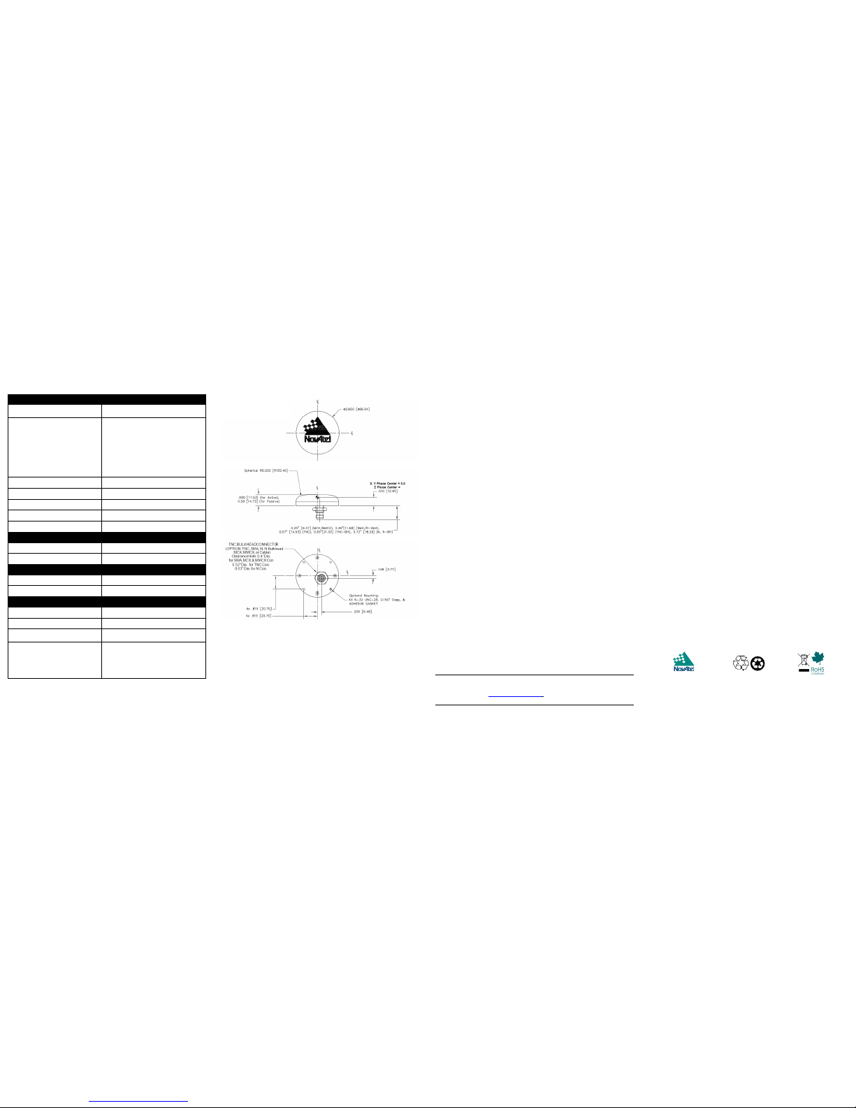
SPECIFICATIONS MECHANICAL DRAWINGS WARRANTY POLICY
NovAtel Inc. warrants that its Global Positioning System (GPS) products are free from
defects in materials and workmanship, subject to the conditions set forth below, for the
following periods of time:
GNSS Antenna Modules: One (1) Year from date of sale
Cables and Accessories: Ninety (90) Days from date of sale
Date of sale shall mean the date of the invoice to the or iginal customer for the product.
NovAtel's responsibility respecting this warranty is limited solely to product repair at an
authorized NovAtel location only. Determination of repair will be made by NovAtel
personnel or by technical personnel expressly authorize d by NovAtel for this purpose.
The foregoing warranties do not extend to
(i) nonconformities, defects or errors in the products due to acciden t, abuse, misuse or
negligent use of the products or use in other than a normal and customary mann er,
environmental conditions not conforming to NovAtel’s specificatio ns, or failure to follow
prescribed installation, operating and maintenance procedures, (ii) defects, errors or
nonconformities in the products due to modifications, alterations, additions or changes
not made in accordance with NovAtel’s specificatio ns or authorized by NovAtel, (iii)
normal wear and tear, (iv) damage cause by force of nature or ac t of any third person,
(v) shipping damage; or (vi)service or repair of product by the deal er without prior
written consent from NovAtel.
In addition, the foregoing warranties shall not apply to products designated by NovAtel
as beta site test samples, experimental, developmental, preproduction, sample,
incomplete or out of specification products or to returned products if the original identification marks have been removed or altered.
The warranties and remedies are exclusive and all other warrantie s, express or
implied, written or oral, including the implied warranties of merchantability or fitness for
any particular purpose are excluded.
NovAtel shall not be liable for any loss, damage or expense arising directly or indirectly
out of the purchase, installation, operation, use or licensing or pr oducts or services. In
no event shall NovAtel be liable for special, indirect, incidental or consequential
damages of any kind or nature due to any cause.
There are no user-serviceable parts in the ANT-26C1GA-TBW-N or ANT-26C1GATBW-AN and no maintenance is required. If the unit is faulty, replace with another unit
and return the faulty unit to NovAtel Inc. You must obtain a RETURN MATERIAL
AUTHORIZATION (RMA) number by calling NovAtel Customer Service at 1-800NOVATEL (U.S. and Canada only) or 403-295-4900 before shipping any product to
NovAtel or a dealer. Once you have obtained an RMA number, you will be advised of
proper shipping procedures to return any defective produc t. When returning any
product to NovAtel, please return the defective product i n the original packaging to
avoid damage.
Before shipping any material to NovAtel or our Dealer, please obtain a Return
Material Authorization (RMA) number from the point of purchase. You may also
visit our website (http://www.novatel.com) and proceed to Registered Services
from our Home page.
WEEE NOTICE
If you purchased your ANT-26C1GA-TBW-N or ANT-26C1GA-TBW-AN
in Europe, please return it to your dealer or supplier at the end of its life.
The objectives of the European Community's environment policy are, in
particular, to preserve, protect and improve the quality of the environment, protect human health and utilise natural resources prudently and
rationally. Sustainable development advocates the reduction of wasteful
consumption of natural resources and the prevention of pollution. Waste
electrical and electronic equipment (WEEE) is a regulated area. Where
the generation of waste cannot be avoided, it should be reused or
recovered for its material or energy. WEEE products may be recognised
by their wheeled bin label.
RoHS NOTICE
The ANT-26C1GA-TBW-N and ANT-26C1GA-TBW-AN are
compliant with the European Union (EU) Restriction of
Hazardous Substances (RoHS) Directive 2002/95/EC.
QUESTIONS OR COMMENTS
If you have any questions or comments regarding your ANT26C1GA-TBW-N or ANT-26C1GA-TBW-AN antenna, please
contact NovAtel Customer Service using one of methods
provided below.
Email: support@novatel.com
Web: www.novatel.com
Phone: 1-800-NOVATEL (U.S. & Canada)
403-295-4900 (International)
Fax: 403-295-4901
© Copyright 2006-2009 NovAtel Inc. All rights reserved. Unpublished rights reserved under
international copyright laws. Recyclable.
OM-20000114 Rev 3 August 26, 2009
RF
3 dB pass band (typical) L1 (1575.42 ±12 MHz)
Antenna Gain (dBic)
where G.P. = Ground Plane
90° zenith
10° elevation
20° elevation
30° elevation
60°-90° elevation
Free Space
+5.0
-2.3
-0.9
+0.7
>4.2
LNA gain 33 dB
Polarization Right-hand circular
Noise figure (typical) 2.4 dB
Nominal impedance 50 Ω
VSWR < 1.5 : 1
POWER
Input voltage 2.5 - 24.0 VDC
Current (typical) < 30 mA
PHYSICAL
Radome Diameter x Height 6.60 cm (2.60”) x 1.75 cm (0.690”)
Weight 113 g (4.0 oz.)
ENVIRONMENTAL
Maximum altitude 21336 m (70000 ft.)
Operating/Storage temperature -55°C to +85°C (-67°F to +185°F)
Vibration >30 G
Designed to meet these
standards
FAA TSO-C144, DO-160D,
DO-228, MIL-C-5541, MIL-E-5400,
MIL-E-5400, MIL-I-45208A,
MIL-STD-810 and SAE J1455
Dimensions are in inches
followed by [mm] and
∅
denotes diameter
 Loading...