

Page 1
EuroPak-15a/15aT
Receiver
USER MANUAL
OM-20000100 Rev 5
Page 2

EuroPak-15a Receiver User Manual
Publication Number: OM-20000100
Revision Level: 5
Revision Date: 2007/04/26
Associated Firmware Version: L1/E5a 5.101 or higher
NovAtel® and Narrow Correlator® tracking technology are registered trademarks of NovAtel Inc.
All other brand names are trademarks of their respective holders.
Proprietary Notice
© Copyright NovAtel Inc. (2006-2007). All rights reserved.
Unpublished rights reserved under International copyright laws.
Printed in Canada on recycled paper. Recyclable.
2 EuroPak-15a Receiver User Manual Rev 5
Page 3

Table of Contents
Notices 9
Software License 11
Warranty Policy 13
Customer Service 14
Foreword 15
1 Introduction 16
1.1 Overview of the EuroPak-15a........................................................................................................ 16
1.2 SBAS Overview............................................................................................................................. 16
1.3 Galileo Overview......................... ... ... ... ... .... ... ... ... .... ................................................... ...................17
1.3.1 Open Service ... .... ... ... ................................................. ... ... ... ... ............................................. 18
1.3.2 Commercial Service.................................................................... ... ...................................... 18
1.3.3 Safety-of-Life Service........................................................... ... .... ... ... ... .... ............................ 19
1.3.4 Public Regulated Service..................................................................................................... 19
1.3.5 Search and Rescue Service. ... ... ................................................. ... ... ... .... ... ... ... ...................19
1.4 EuroPak-15a Enclosure . ... ... ... .... ... ................................................... .... ... ... ... .... ... ... ... ... .... ............19
1.5 EuroPak-15a Features................................ ... ... ... .... ... ... ... .... ... ... ... ... .... ... ...................................... 20
1.5.1 GEO Signal Processing .......................................................................................................21
1.5.2 Digital Pulse Blanking ....................................... ... ... .... ... ... ... ................................................ 21
1.6 Functional Overview................................................... ... ... .... ... ... ... ... .... ......................................... 21
1.7 Internal Euro-L1E5a Card . ... ... .... ... ... ... ... .... ................................................... .... ... ... ...................... 21
1.7.1 Radio Frequency Section..................................................................................................... 21
1.7.2 Digital Electronics Section.................................... ... .... ... ... ... ................................................ 22
1.8 Antenna or Signal Generator............... ... .... ... ... ... .... ... ... ... .... .........................................................22
1.9 Principal Power Supply .................................................. ... .... ... ... ................................................... 22
1.10 Data Communications Equipment............................................................................................... 22
2 Installation 23
2.1 Additional Equipment Required..................................................................................................... 23
2.1.1 Selecting an Antenna or Signal Generator........................................................................... 23
2.1.2 Choosing a Coaxial Cable.................................................................................................... 23
2.1.3 Power Supply Requirements................................................................................................ 24
2.2 Installation Overview................... ... ... ... ... .... ... ... ... .... ................................................... ...................24
2.2.1 Mounting the Antenna or Signal Generator..........................................................................25
2.2.2 Connecting the Antenna or Signal Generator to the Receiver............................................. 25
2.2.3 Applying Power to the Receiver........................................................................................... 26
2.2.4 Connecting Data Communications Equipment .................................................................... 26
2.3 Additional Features and Information..............................................................................................26
2.3.1 Strobes....................... ................................................. ... ... ... ................................................ 26
2.3.2 Status Indicators .. ... ... ... .... ... ... ... ... ................................................. ... ... .... ... ... ... ... ................27
2.3.3 External Oscillator................................................................ ... .... ... ... ................................... 27
2.3.4 Mounting Bracket .................................... ... .... ... ... ... .... ... ... ... ................................................ 27
3 Operation 28
3.1 Pre-Start Check List....................... ... ................................................ .... ... ... ... .... ... ......................... 28
3.2 Start-Up ............................ ... ... .... ... ... ................................................ .... ... ... ... .... ... ......................... 28
3.3 Communicating with the EuroPak-15a ..........................................................................................29
3.4 Getting Started............................................................................................................................... 29
3.4.1 Starting the Receiver............................................................................................................ 29
EuroPak-15a Receiver User Manual Rev 5 3
Page 4

Table of Contents
3.4.2 Communicating with the Receiver Using GPSolution (Aviation) ..........................................29
4 Using Commands and Logs 31
4.1 Entering Commands.. .... ... ... ... .... ... ... ... .... ...................................................................................... 31
4.1.1 Command Settings on Power-Up.........................................................................................31
4.1.2 Determining the Current Command Settings ....................................................................... 32
4.1.3 Response Formats.................. ... .... ... ... ... ... .... ... ... ... .... ......................................................... 32
4.1.4 Response Messages .. ... .... ... ... ... .... ... ... ... ... .... ................................................... .... ... ... ... ...... 32
4.2 Logging Data ................. ... ... ... .... ................................................ ... .... ... ... ... ... .... ............................34
4.2.1 Log Types................................... .... ... ... ... .............................................................................34
4.2.2 Log Triggers................................................................ ... ... ... .... ... ... ... ... .... ............................34
4.2.3 Specifying Log Formats.............................. .... ... ... ... .... ... ... ... ................................................ 35
4.3 Log Formats...................... ... ... .................................................... ................................................... 35
4.3.1 ASCII................ .... ... ... ... ................................................. ... ... .... ... ......................................... 35
4.3.2 Binary............................................................. ................................................ ... ...................36
4.4 Fields................................................... .... ... ... ................................................ .... ... .........................38
4.4.1 Field Types.... .................................................................................................... ...................38
4.4.2 Commonly-Used Fields........... ... .... ... ... ... ... .... ... ... ... .... ... ...................................................... 39
5 Commands 43
5.1 Functional Listing of Commands ................................................................................................... 43
5.2 Command Summary......................................... ... .... ... ... ... .... ... ... ................................................... 44
5.3 Command Reference.............. .... ... ... ... .... ... ... ... ... ..........................................................................45
5.3.1 AGCMODE Control Automatic Gain Control ..................................................................... 45
5.3.2 ASSIGN Assign Individual Satellite Channels...................................................................47
5.3.3 CHANCONFIG.................................................. ... ... .... ... ... ... .... ............................................ 49
5.3.4 CLOCKADJUST...... ... ... .... ... ... ... .... ................................................ ... ... .... ... ... ... ...................50
5.3.5 COM Serial Port Configuration Control..................................... ... ... ... .... ... ... ... ...................51
5.3.6 ECUTOFF Set Satellite Elevation Cut-off..........................................................................53
5.3.7 EXTERNALCLOCK.............. ... ... .... ... ... ... ... .................................................... ... .... ... ... .........54
5.3.8 FIX Constrain to Fixed Position............................................................. ... ... ... .... ...............56
5.3.9 FRESET Clear Data in NVM..............................................................................................58
5.3.10 LOG Request Logs from Receiver................................................................................... 59
5.3.11 POSITIONTYPE Set the Position Solution......................................................................61
5.3.12 PULSEBLANKING Enable/Disable Pulse Blanking.........................................................62
5.3.13 RESET Hardware Reset..................................................................................................63
5.3.14 SDLLBW Configure DLL Filter Bandwidth.......................................................................64
5.3.15 SPLLBW Configure Phase-Lock-Loop Bandwidth........................................................... 65
5.3.16 STHRESHOLD Control Signal Thresholds...................................................................... 66
5.3.17 UNASSIGN Unassign a Previously Assigned Channel...................................................67
5.3.18 UNLOG Remove Log from Logging Control....................................................................68
5.3.19 UNLOGALL Remove All Logs from Logging Control.......................................................69
6 Data Logs 70
6.1 Functional Listing of Logs..............................................................................................................70
6.2 Log Summary ...................... ... .... ... .................................................... ............................................ 71
6.3 Log Reference............... ... ... ... .................................................... ................................................... 71
6.3.1 AGCSTATS Automatic Gain Control Status......................................................................72
6.3.2 ALMANAC Decoded Almanac................. .... ... ... ... .... ................................................... ... ... 75
6.3.3 CLOCKMODEL Current Clock Model Status..................................................................... 77
6.3.4 PSRPOS Pseudorange Position........................................ .... ... ... ... ... .... ... ... ... .... ... ... ... ... ... 80
6.3.5 RANGE Satellite Range Information......................... ... ... ... .... ... ... ... ................................... 82
6.3.6 RAWEPHEM Raw Ephemeris.............................. .... ... ... ... .... ... ... ... ................................... 86
6.3.7 RAWFRAME Raw Subframes..................................... ... ... .... ... ... ... ... .... ... ... ... .... ... ... ... ... ... 87
4 EuroPak-15a Receiver User Manual Rev 5
Page 5

Table of Contents
6.3.8 RXCOMMANDS Receiver Configuration . .... ... ... ... .... ... ... ... ................................................ 88
6.3.9 RXSECSTATUS Receiver Section Status......................................................................... 91
6.3.10 SATVIS Satellite Visibility................................................................................................ 94
6.3.11 SYSTEMLEVELS System Hardware Levels................................................................... 96
6.3.12 TIME Time Data .............................................................................................................. 97
6.3.13 TRACKSTAT Tracking Status......................................................................................... 98
6.3.14 VERSION Version Information ......................................................................................100
7 Firmware Updates 102
7.1 Contacting the NovAtel Aviation Department .............................................................................. 102
7.2 Downloading the Files ......................... ... ................................................. ... ... .... ... ... ... ... ..............103
7.3 Decompressing the Files..................... ... .... ... ... ... .... ... ................................................... .... ..........103
7.4 Running the Utility........................................................................................................................ 104
7.4.1 Open a File to Download....................................................................................................104
7.4.2 Communications Settings ....... ... ... .... ... ... ... .... ... ... .................................................... ... ... ... . 105
7.4.3 Downloading Firmware . .... ... ... ... ... .... .................................................................................105
8 Built-In Status Test 107
8.1 Overview........................................... ... ... ................................................. ... ... .... ... ....................... 107
8.2 Receiver Status Word.......................................... .... ... ... ..............................................................107
8.3 Error Strobe Signal...................................................................................................................... 107
8.4 Receiver Status Log ......................... ... ... .... ... ... ... .... ... ... ..............................................................107
8.4.1 Overview .............................. ... ... ... ................................................. ... ... .... ... .......................107
8.4.2 Error Word........ .... ................................................ ... .... ... ... ... ... .... ....................................... 108
8.4.3 Status Code Arrays............................................................................................................ 109
8.4.4 Receiver Status Code ................................ .... ... ... ... .... ... ... ... ... .... ....................................... 109
8.4.5 Auxiliary Status Codes............................... .... ... ................................................... ..............109
Appendices
A Technical Specifications 110
B Electrostatic Discharge Control (ESD) Practices 123
C Standards/References 125
D Replacement Parts 126
EuroPak-15a Receiver User Manual Rev 5 5
Page 6

Figures
1 The SBAS Concept....................................................................................................................... 17
2 EuroPak-15a Enclosure ................................................................................................................ 20
3 Typical Receiver Installation..........................................................................................................25
4 The WGS84 ECEF Coordinate System ........................................................................................57
5 Serial Number and Version Label ...............................................................................................102
6 Main Screen of WinLoad............................................................................................................. 104
7 WinLoad’s Open Dialog.................................... ... .... ... ... .................................................... ... ....... 104
8 Open File in WinLoad..................................................................................................................105
9 COM Port Setup..........................................................................................................................105
10 Authorization Code Dialog........................................................................................................... 106
11 Update Process Complete .......................................................................................................... 106
12 Location of Receiver Status Word............................................................................................... 108
13 Reading the Bits in the Receiver Status Word............................................................................108
14 Location of Receiver Error Word.................................................................................................108
15 Reading the Bits in the Receiver Error Word .......................... ... ... .... ... ... ... ... .... ... ... ... .... .............108
16 EuroPak-15a Power Cable..........................................................................................................115
17 EuroPak-15a Null Modem Cable.................................................................................................116
18 EuroPak-15a Straight Through Serial Cable...............................................................................117
19 EuroPak-15a I/O Strobe Port Cable............................................................................................ 118
6 EuroPak-15a Receiver User Manual Rev 5
Page 7

Tables
1 Default Serial Port Configurations ................................ .................................................... ... ... ......26
2 Available Strobe Signals on the EuroPak-15a ............................................................................. 27
3 EuroPak-15a Status Indicators .................................................................................................... 27
4 Response Messages ....................................................................................................................33
5 Log Triggers for Each Log Type ................................................................................................... 34
6 ASCII Message Header Structure ................................................................................................36
7 Binary Message Header Structure ...............................................................................................37
8 Field Types ................................................................................................................................... 38
9 Byte Arrangements ......................................................................................................................39
10 Serial Port Identifier Values ................ ... .... ... .................................................... ... ... ... ... ................39
11 Message Type Byte Format ......................................................................................................... 39
12 GPS Time Status ........................................................................................................................ 40
13 Commands By Function ............................... ................................................................................ 43
14 Command Summary ....................................................................................................................44
15 Frequency Values for AGCMODE Command ..............................................................................45
16 AGC Mode Values .......................................................................................................................45
17 Antispoofing Flag Values ................ ... ... .... ................................................... .... ... ... ...................... 46
18 Channel State Values ..................................................................................................................48
19 Configuration Values .................................... ... .................................................... ... ... ... ................49
20 Parity Values ................................................................................................................................ 52
21 Handshaking Values .................................................................................................................... 52
22 Echo Values .... ... ... ... .... ................................................ ... .... ... ... ... ... .... ......................................... 52
23 Break Values ................................................................................................................................ 52
24 Clock Type ................................................................................................................................... 55
25 Pre-Defined Values for Oscillators ............................................................................................... 55
26 Fix Type Values ...........................................................................................................................56
27 Log Trigger Values ....................................................................................................................... 60
28 Log Hold Values ........................................................................................................................... 60
29 Position Frequency Switch ........................ ... ... ... .... ... ... ... .................................................... .........61
30 Frequency Switch .........................................................................................................................62
31 Pulse Blanking Switch ........................ ... .... ... ... ... .... ................................................ ... ... .... ............62
32 PLL Bandwidth Values ................................................................................................................. 65
33 Logs By Function .........................................................................................................................70
34 Log Summary ............................................................................................................................... 71
35 AGC Status Word .........................................................................................................................73
36 Clock Model Status Values .......................................................................................................... 79
37 Constellation Change Flag Values ............................................................................................... 79
38 Solution Status Values ................................................................................................................. 81
39 Position Type Values ......... ... .... ... ... ... ... ................................................. ... ... .... ... ... ... ... ................81
40 Channel Tracking Status .............................................................................................................. 84
41 Tracking State Bit Values ....................................... ... ... ... .... ... ... ................................................... 85
42 Correlator Spacing Bit Values ...................................................................................................... 85
43 Command Type Values ................................................................................................................ 90
44 Component Type ..........................................................................................................................91
45 Receiver Error .............................................................................................................................. 92
46 Receiver Status ............................................................................................................................ 93
47 Satellite Visibility Values ....... .... ... ... ... ... ....................................................................................... 95
48 Complete Almanac Flag Values ...................... ....................................................... ......................95
49 Reject Code Values .....................................................................................................................99
50 Version Log Field Formats ...................................................................................................
51 Target Card Identification ........................................................................................................... 105
...... 101
EuroPak-15a Receiver User Manual Rev 5 7
Page 8

Tables
52 Performance Specifications ............................. ... .... ... ... ... .... ... .................................................... 110
53 EuroPak-15a Serial Port Pin-Out Descriptions ...........................................................................114
54 EuroPak-15a I/O Port Pin-Out Descriptions .................... ........................................................... 114
55 10GALILEO6GPS Channel Configuration ....................... .... ... ... ... .... ... ... ... ... .... ... ... ... .... ... ... ... ... . 120
56 16GPSL1L5 Channel Configuration ....................................... .................................................... 120
57 16GALILEOL1E5a Channel Configuration ................................................................................. 121
58 12GPS4GEOL1L5 Channel Configuration ............................. .................................................... 121
59 8GPS8GEO Channel Configuration ....................... ... ... ... .... ... ... ... .... ... ....................................... 122
60 16GPSL5 Channel Configuration ............................................................................................... 122
61 Static-Accumulating Materials .................................................................................................... 124
8 EuroPak-15a Receiver User Manual Rev 5
Page 9

Notices
Notices
The following notices apply to the EuroPak-15a.
FCC NOTICE
This equipment has been tested and found to comply with the radiated and conducted emission limits for a
Class B digital device, for both CISPR 22 and Part 15 of the FCC rules. These limits are designed to provide
reasonable protection against harmful interference in a residential installation. This equipment generates, uses,
and can radiate radio frequency energy and, if not installed and used in accordance with the instructions, may
cause harmful interference to radio communications. However, there is no guarantee that interference will not
occur in a particular installation. If this equipment does cause harmful interference to radio or television
reception, which can be determined turning the equipment off and on, the user is encouraged to try to correct
the interference by one or more of the following measures:
• Re-orient or relocate the receiving antenna
• Increase the separation between the equipment and the receiver
• Connect the equipment to an outlet on a circuit different from that to which the receiver is
connected
• Consult the dealer or an experienced radio/TV technician for help
IMPORTANT: In order to maintain compliance with the limits of a Class B digital device, it is required to
use properly shielded interface cables (such as Belden #9539 or equivalent) when using the
serial data ports, and double-shielded cables (such as Belden #9945 or equivalent) when
using the I/O strobe port.
WARNING: Changes or modifications to this equipment not expressly approved by NovAtel Inc. could
result in violation of Part 15 of the FCC rules.
CE NOTICE
The enclosure carries the CE mark.
WARNING: This is a Class B product. In a domestic environment this product may cause radio
interference in which case the user may be required to take adequate measures.
"Hereby, NovAtel Inc. declares that this EuroPak-15a is in compliance with the essential requirements and
other relevant provisions of Directive 1999/5/EC."
EuroPak-15a Receiver User Manual Rev 5 9
Page 10

Electromagnetic Compatibility (EMC)
The EuroPak-15a has passed the following EMC regulatory tests:
Emissions Testing of the EUROPAK-15a
• EN 55022 1998 (CISPR 22 (2006)) - Information technology equipment - Radio disturbance
characteristics - Limits and methods of measurement
• FCC, Part 15 Subpart B (2004)
Immunity Testing of the EUROPAK–15a
• EN 61000-6-1: 2001 – Immunity Requirement s for Residen tial , Com mercial and Light
Industrial Environments
Safety of Information Technology Equipment
• IEC/EN 60950
Notices
10 EuroPak-15a Receiver User Manual Rev 5
Page 11

Software License
Software License
BY INSTALLING, COPYING, OR OTHERWISE USING THE SOFTWARE PRODUCT, YOU AGREE
TO BE BOUND BY THE TERMS OF THIS AGREEMENT . IF YOU DO NOT AGREE TO THE TERMS
OF THIS AGREEMENT, DO NOT INSTALL, COPY OR USE THE SOFTWARE PRODUCT.
1. License: NovAtel Inc. ("NovAtel") grants you a non-exclusive, non-transferable license (not a sale) to use
one copy of the enclosed NovAtel software on a single computer, and only with the product it was supplied
with. You agree not to use the software for any purpose ot her than the due exercise of the rights and
licences hereby agreed to be granted to you.
2. Copyright: NovAtel owns, or has the right to sublicense, all copyright, trade secret, patent and other
proprietary rights in the software and the software is protected by national copyright laws, international
treaty provisions and all other applicable national laws. You must treat the software like any other
copyrighted material except that you may either (a) make one copy of the software solely for backup or
archival purposes, the media of said copy shall bear labels showing all trademark and copyright notices
that appear on the original copy, or (b) transfer the software to a single hard disk provided you keep th e
original solely for backup or archival purposes. You may not copy the product manual or written materials
accompanying the software. No right is conveyed by this Agreement for the use, directly, indirectly, by
implication or otherwise by Licensee of the name of NovAtel, or of any trade names or nomenclature used
by NovAtel, or any other words or combinations of words proprietary to NovAtel, in connection with this
Agreement, without the prior written consent of NovAtel.
3. Patent Infringement: NovAtel shall not be liable to indemnify the Licensee against any loss sustained by it
as the result of any claim made or action brought by any third party for infringement of any letters patent,
registered design or like instrument of privilege by reason of the use or application of the software by the
Licensee or any other information supplied or to be supplied to the Licensee pursuant to the terms of this
Agreement. NovAtel shall not be bound to take legal proceedings against any third party in respect of any
infringement of letters patent, registered design or like instrument of privilege which may now or at any
future time be owned by it. However, should NovAtel elect to take such legal proceedings, at NovAtel's
request, Licensee shall co-operate reasonably with NovAtel in all legal actions concerning this license of
the software under this Agreement taken against any third party by NovA tel to protect its rights in the
software. NovAtel shall bear all reasonable costs and expenses incurred by Licensee in the course of cooperating with NovAtel in such legal action.
4. Restrictions: You may not: (1) copy (other than as provided for in paragraph 2), distribute, transfer, rent,
lease, lend, sell or sublicense all or any portion of the software; (2) modify or prepare derivative works of
the software; (3) use the software in connection with computer-based services business or publicly display
visual output of the software; (4) transmit the software over a network, by telephone or electronically using
any means; or (5) reverse engineer, decompile or disassemble the software. You agree to keep confidential
and use your best efforts to prevent and protect the contents of the software from unauthorized disclosure
or use.
5. Term and Termination: This Agreement and the rights and licences hereby granted shall continue in force
in perpetuity unless terminated by NovAtel or Licensee in accordance herewith. In the event that the
Licensee shall at any time during the term of this Agreement: i) be in breach of its obligations hereunder
where such breach is irremediable or if capable of remedy is not remedied within 30 days of notice from
NovAtel requiring its remedy; or ii) be or become bankrupt or insolvent or make any composition with its
creditors or have a receiver or manager appointed of the whole or any part of its undertaking or assets or
EuroPak-15a Receiver User Manual Rev 5 11
Page 12

Software License
(otherwise as a solvent company for the purpose of and followed by an amalgamation or reconstruction
hereunder its successor shall be bound by its obligations hereunder) commence to be wound up; or iii) be
acquired or otherwise come under the direct or indirect control of a person or persons other than those
controlling it, then and in any event NovAtel may forthwith by notice in writ ing terminate this Agreement
together with the rights and licences hereby granted by NovAtel. Licensee may terminate this Agreement
by providing 30 days prior written notice to NovAtel. Upon termination, for any reasons, the Licensee shall
promptly, on NovAtel's request, return to NovAtel or at the election of NovAtel destroy all copies of any
documents and extracts comprising or containing the software. The Licensee shall also erase any copies of
the software residing on Licensee's computer equipment. Termination shall be without prejudice to the
accrued rights of either party , including payments due to NovAtel. This provision shall s urvive termination
of this Agreement howsoever arising.
6. Warranty: For 90 days from the date of shipment, NovAtel warrants that the media (for example, compact
disk) on which the software is contained will be free from defects in materials and workmanship. This
warranty does not cover damage caused by improper use or neglect. NovAtel does not warrant the contents
of the software or that it will be error free. The software is furnished "AS IS" and without warranty as to the
performance or results you may obtain by using the software. The entire risk as to the results and
performance of the software is assumed by you.
7. Indemnification: NovAtel shall be under no obligation or liability of any kind (in contract, tort or otherwise
and whether directly or indirectly or by way of indemnity contribution or otherwis e howsoever) to the
Licensee and the Licensee will indemnify and hold NovAtel harmless against all or any loss, damage,
actions, costs, claims, demands and other liabilities or any kind whatsoever (direct, consequential, special
or otherwise) arising directly or indirectly out of or by reason of the use by the Licensee of the software
whether the same shall arise in consequence of any such infringement, deficiency, inaccuracy, error or
other defect therein and whether or not involving negligence on the part of any person.
8. For software UPDA TES and UPGRADES, and regular customer support, contact the NovAtel GPS Hotline
at 1-800-NOVATEL (U.S. or Canada only), or 403-295-4900, or fax 403-295-4901, e-mail to
support@novatel.ca, visit our website http://www.novatel.com or write to:
NOVATEL INC.
CUSTOMER SERVICE DEPT.
1120 - 68 AVENUE NE,
CALGARY, ALBERTA, CANADA T2E 8S5
9. Disclaimer of Warranty and Limitation of Liability:
a. THE WARRANTIES IN THIS AGREEMENT REPLACE ALL OTHER WARRANTIES, EXPRESS
OR IMPLIED, INCLUDING ANY WARRANTIES OF MERCHANTABILITY OR FITNESS FOR A
PARTICULAR PURPOSE. NovAtel DISCLAIMS AND EXCLUDES ALL OTHER WARRANTIES.
IN NO EVENT WILL NovAtel's LIABILITY OF ANY KIND INCLUDE ANY SPECIAL,
INCIDENTAL OR CONSEQUENTIAL DAMAGES, INCLUDING LOST PROFITS, EVEN IF
NovAtel HAS KNOWLEDGE OF THE POTENTIAL LOSS OR DAMAGE.
b. NovAtel will not be liable for any loss or damage caused by delay in furnishing the software or any other
performance under this Agreement.
c. NovAtel's entire liability and your exclusive remedies for our liability of any kind (including liability
for negligence) for the software covered by this Agreement and all other performance or non-performance by NovAtel under or related to this Agreement are to the remedies specified by this Agreement.
This Agreement is governed by the laws of the Province of Alberta, Canada. Each of the parties
hereto irrevocably attorns to the jurisdiction of the courts of the Province of Alberta.
12 EuroPak-15a Receiver User Manual Rev 5
Page 13

Warranty Policy
Warranty Policy
NovAtel Inc. warrants that its Global Positioning System (GPS) products are free from defects in materials and
workmanship, subject to the conditions set forth below, for the following periods of time:
Date of sale shall mean the date of the invoice to the original customer for the product. NovAtel’s responsibility
respecting this warranty is solely to product replacement or product repair at an authorized NovAtel location.
Determination of replacement or repair will be made by NovAtel personnel or by technical personnel expressly
authorized by NovAtel for this purpose.
THE FOREGOING WARRANTIES DO NOT EXTEND TO (I) NONCONFORMITIES, DEFECTS OR
ERRORS IN THE PRODUCTS DUE TO ACCIDENT, ABUSE, MISUSE OR NEGLIGENT USE OF
THE PRODUCTS OR USE IN OTHER THAN A NORMAL AND CUSTOMARY MANNER, ENVIRONMENTAL CONDITIONS NOT CONFORMING TO NOVATEL’S SPECIFICATIONS, OR FAILURE TO FOLLOW PRESCRIBED INSTALLATION, OPERATING AND MAINTENANCE
PROCEDURES, (II) DEFECTS, ERRORS OR NONCONFORMITIES IN THE PRODUCTS DUE TO
MODIFICATIONS, ALTERATIONS, ADDITIONS OR CHANGES NOT MADE IN ACCORDANCE
WITH NOVATEL’S SPECIFICATIONS OR AUTHORIZED BY NOVATEL, (III) NORMAL WEAR
AND TEAR, (IV) DAMAGE CAUSED BY FORCE OF NATURE OR ACT OF ANY THIRD PERSON,
(V) SHIPPING DAMAGE; OR (VI) SERVICE OR REPAIR OF PRODUCT BY THE DEALER WITHOUT PRIOR WRITTEN CONSENT FROM NOVATEL. IN ADDITION, THE FOREGOING WARRANTIES SHALL NOT APPL Y T O PRODUCTS DESIGNATED BY NOVATEL AS BETA SITE TEST
SAMPLES, EXPERIMENTAL, DEVELOPMENTAL, PREPRODUCTION, SAMPLE, INCOMPLETE
OR OUT OF SPECIFICATION PRODUCTS OR TO RETURNED PRODUCTS IF THE ORIGINAL
IDENTIFICATION MARKS HAVE BEEN REMOVED OR ALTERED. THE WARRANTIES AND
REMEDIES ARE EXCLUSIVE AND ALL OTHER W ARRANTIES, EXPRESS OR IMPLIED, WRITTEN OR ORAL, INCLUDING THE IMPLIED WARRANTIES OF MERCHANTABILITY OR FITNESS FOR ANY PARTICULAR PURPOSE ARE EXCLUDED. NOVATEL SHALL NOT BE LIABLE
FOR ANY LOSS, DAMAGE, EXPENSE, OR INJURY ARISING DIRECTLY OR INDIRECTLY OUT
OF THE PURCHASE, INSTALLATION, OPERATION, USE OR LICENSING OR PRODUCTS OR
SERVICES. IN NO EVENT SHALL NOVATEL BE LIABLE FOR SPECIAL, INDIRECT, INCIDENTAL OR CONSEQUENTIAL DAMAGES OF ANY KIND OR NATURE DUE TO ANY CAUSE.
EuroPak-15a Receivers One (1) Year from date of sale
NovAtel Antennas One (1) Year from date of sale
Cables and Accessories Ninety (90) Days from date of sale
Software Support One (1) Year from date of sale
There are no user serviceable parts in the GPS receiver and no maintenance is required. When the status code indicates
that a unit is faulty, replace with another unit and return the faulty unit to NovAtel Inc.
Before shipping any material to NovAtel or Dealer, please obtain a Return Material Authorization (RMA)
number from the point of purchase. You may also visit our website at http://www.novatel.com
Support | Repair Request from the side menu.
Once you have obtained an RMA number, you will be advised of proper shipping procedures to return any defective
product. When returning any product to NovAtel, please return the defective product in the original packaging to avoid
ESD and shipping damage.
and select
EuroPak-15a Receiver User Manual Rev 5 13
Page 14

Customer Service
Customer Service
Contact Information
If you have any questions or concerns regarding your EuroPak-15a receiver, please contact the NovAtel
Aviation Group using any one of the following methods:
NovAtel GPS Hotline: 1-800-NOVATEL (U.S. and Canada)
403-295-4900 (International)
Fax: 403-295-4999
E-mail: support@novatel.ca
Website: www.novatel.com
Write: NovAtel Inc. Aviation Group
1120 - 68 Avenue NE
Calgary, Alberta, Canada
T2E 8S5
Firmware Updates
Firmware updates are firmware revisions to an existing model, which improve basic functionality of the GPS
receiver.
The process for obtaining firmware updates is discussed in Chapter 7, Firmware Updates starting on Page 102.
If you need further information, please contact NovAtel using one of the methods given above.
14 EuroPak-15a Receiver User Manual Rev 5
Page 15

Foreword
Foreword
Scope
This manual contains sufficient information on the installation and operation of the EuroPak-15a or EuroPak15aT receiver to allow you to effectively integrate and fully operate it. After the addition of accessories, usersupplied data communications equipment and a power supply, the receiver is ready to go.
These receivers utilizes a comprehensive user-interface command structure, which requires communications
through its communications (COM) ports. This manual also lists and describes the various receiver commands
and logs.
For an overview of GPS, a glossary of terms, units of conversion and acronyms, refer to the GPS+ Reference
Manual available on our website at http://www.novatel.com/Downloads/docupdates.html
It is beyond the scope of this manual to provide details on service or repair. Please contact your local NovAtel
dealer for any customer-service related inquiries, see Customer Service on Page 14.
Prerequisites
The installation chapters of this document provide information concerning the installation requirements and
considerations for the EuroPak-15a and EuroPak-15aT receivers.
Conventions
.
The term EuroPak-15aT will not be used in this manual unless a specific detail refers to it alone. The term
receiver and the term EuroPak-15a will infer that the text is applicable to a EuroPak-15a or EuroPak-15aT
unless otherwise stated.
The conventions used throughout this document are:
H The letter H in the Binary Bytes or Binary Offset columns represents the header length for that
command or log. The binary header is described in Section 4.3.2 on Page 36.
0x A number following 0x is a hexadecimal number.
field
[ ] Parameters surrounded by [ and ] are optional in a command or are required for only some instances
< > Text displayed between < and > indicates the entry of a keystroke in the case of the command or an
In tables where no values are given, such fields should be assumed to be reserved for future use.
T ext surrounded by a box indicates a variable parameter to be entered as part of the command string.
of the command depending on the values of other parameters.
automatic entry in the case of carriage return
<CR> and line feed <LF> in data output.
Compliance with GPS Week Rollover
The GPS week rollover issue refers to the way GPS receivers store information regarding the current GPS
week. According to the official GPS system specifications document (ICD-GPS-200, paragraph 20.3.3.3.1.1),
"… 10 bits shall represent the number of the current GPS week…". This means the GPS week is represented by
an integer number between 0 and 1023. As GPS time started on Sunday January 6, 1980 at 0:00 hours, week
1023 ended on Saturday August 21, 1999 at 23:59:59.
As per the GPS system specifications document, NovAtel firmware resets the receiver's GPS week number
back to zero. Users should be aware of this issue and keep in mind that there may be a compatibility issue when
purchasing and using different makes of GPS receivers.
EuroPak-15a Receiver User Manual Rev 5 15
Page 16

Chapter 1 Introduction
This chapter provides information on the features and functionality of the EuroPak-15a and how it operates in
the context of an SBAS system.
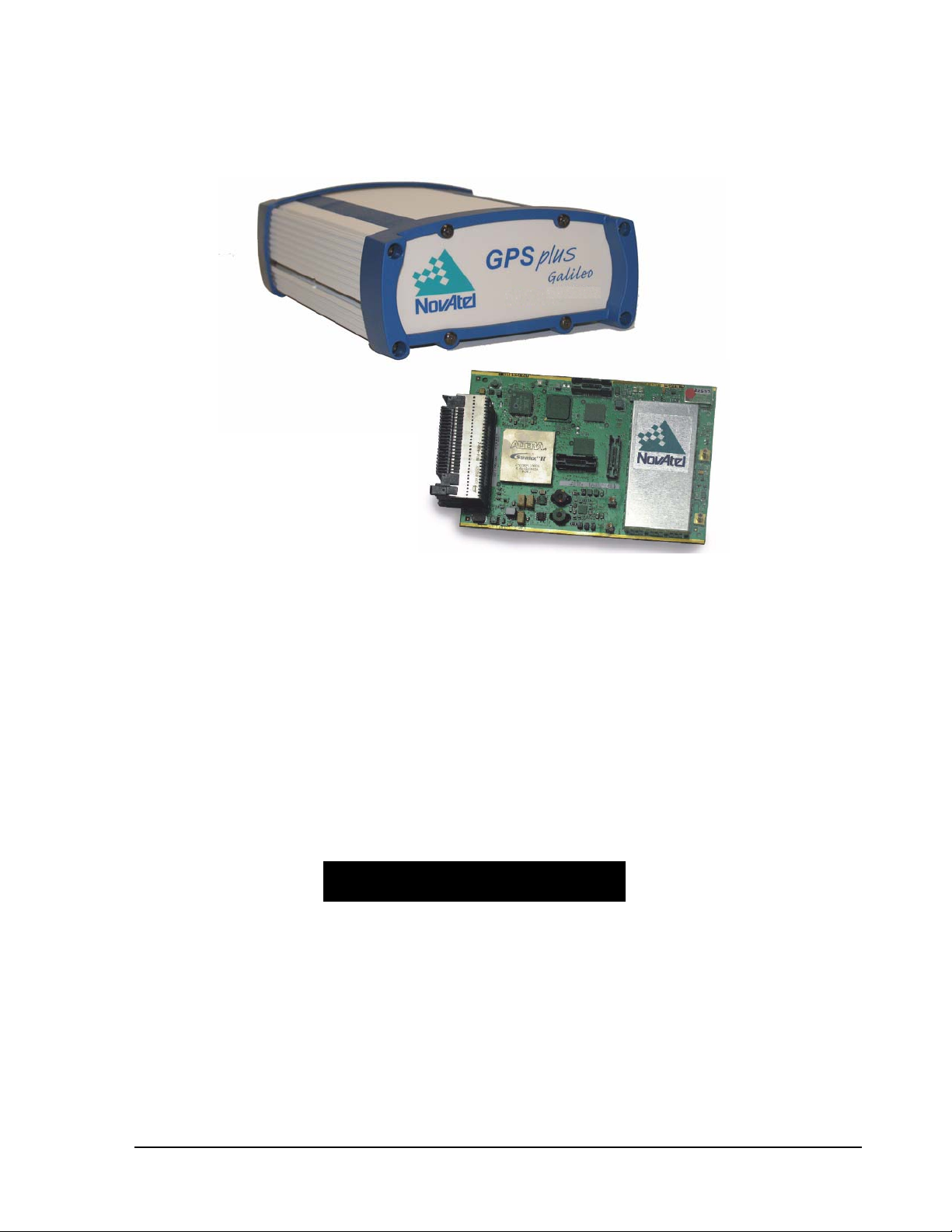
1.1 Overview of the EuroPak-15a
The EuroPak-15a is a high-performance GPS, Galileo and GEO receiver capable of receiving and tracking
sixteen GPS L1, GPS L5, Galileo L1 and Galileo E5a signals. Alternatively, four of the sixteen signals can be
SBAS GEO L1 and SBAS GEO L5 signals. The EuroPak-15a also decodes the navigation signals.
There is flexibility in areas such as configuration and specification of output data and control signals. Multiple
software models are available, allowing you to better fit the receiver to the application while maintaining the
option for a compatible upgrade path.
The EuroPak-15a enclosure offers a complete solution, a protective enclosure that provides an interface to the
receiver card’s power, data, and status signals.
1.2 SBAS Overview
A Satellite-Based Augmentation System (SBAS) is a safety-critical system designed to augment the
Department of Defense Global Positioning System (GPS) Standard Positioning Service (SPS). SBAS enhances
GPS service by providing:
• a ranging function to the SBAS satellites, which improves signal availability and reliability
• GPS signal corrections, which improve accuracy
• int egrity monitoring, which improves safety
The primary mission of the SBAS system is to provide a means for air navigation for all phases of flight in the
National Airspace System (NAS) from departure, through en route, and approach. The principal functions of
SBAS include:
• determi ning ionospheric corrections
• determining satellite orbits
• determining satellite clock corrections
• determining satellite integrity
• ind ependent data verification
• SB A S m e ssage broadcast and ranging
• system operations & maintenance
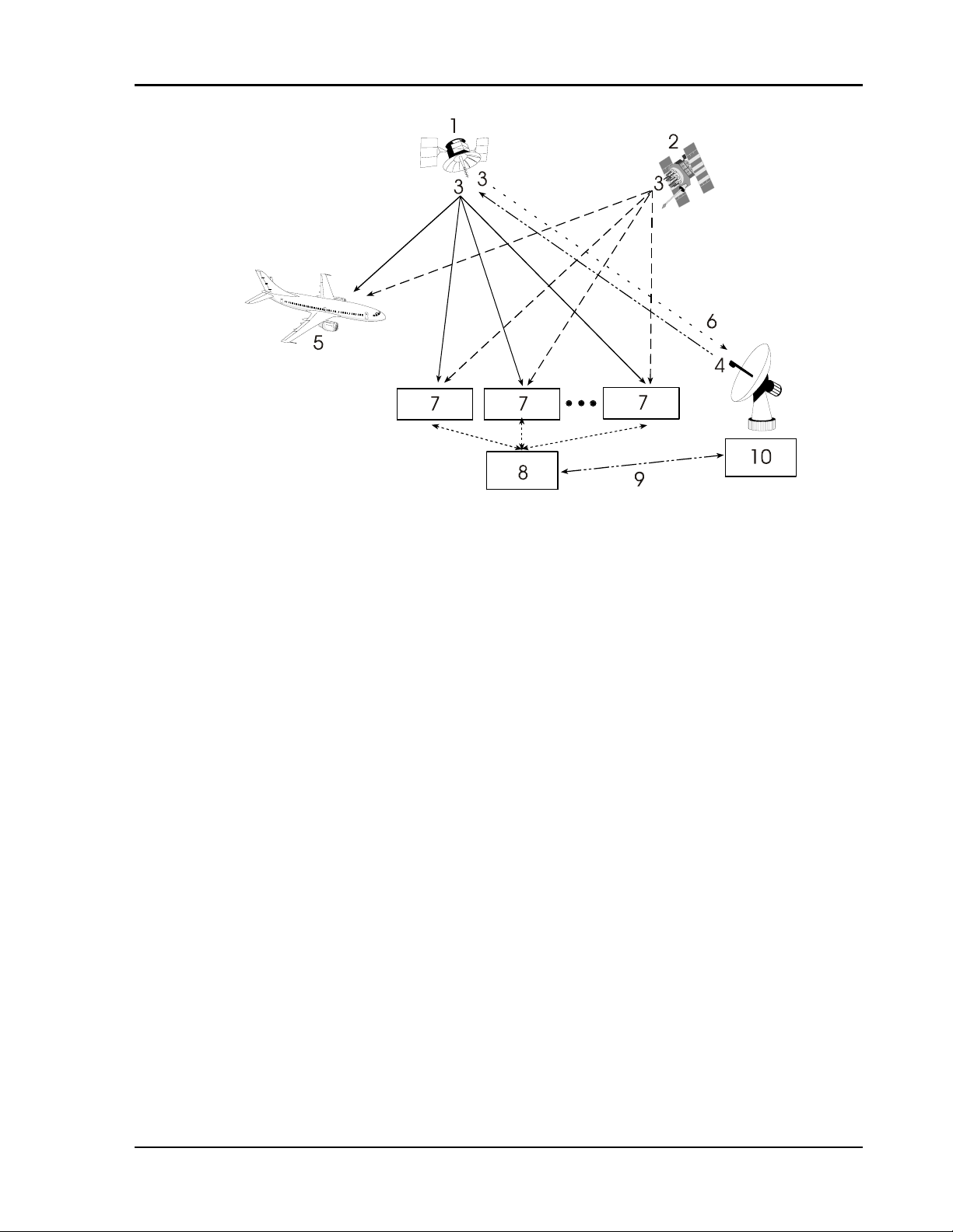
As shown in Figure 1 on Page 17, the SBAS system consists of a series of Reference Stations and Master
Stations, a Ground Uplink Subsystem, and Geostationary Satellites (GEOs). The Reference Stations, which are
strategically located to provide adequate coverage, pick up GPS satellite data and route it to the Master
Stations. The Master Stations then process the data to determine the signal integrity, signal corrections, and
residual errors for each monitored satellite. This information is sent to the Ground Uplink Subsystem for
transmission to the GEOs, which then re-transmits the data on the GPS L1 and L5 (not yet available)
frequency. In the future, the system will support L5 signal frequency broadcasts.
16 EuroPak-15a Receiver User Manual Rev 5
Page 17
Introduction Chapter 1
Figure 1: The SBAS Concept
Reference Description
1 Geo satellite
2 GPS satellite constellation
3 L1 and L5
4 C1 and C5
5 GPS user
6 Integrity data, differential corrections and ranging control
7 Reference station
8 Master station
9 Integrity data, differential corrections, time control and status
10 Ground uplink subsystem
1.3 Galileo Overview
Galileo will be Europe's own global navigation satellite system, providing a highly accurate, guaranteed global
positioning service under civilian control. It will be inter-operable with GPS and GLONASS, the two other
global satellite navigation systems.
A user will be able to take a position with the same receiver from any of the satellites in any combination. By
offering dual frequencies as standard, however, Galileo will deliver real-time positioning accuracy down to the
metre range, which is unprecedented for a publicly available system.
It will guarantee availability of the service under all but the most extreme circumstances and will inform users
within seconds of a failure of any satellite. This will make it suitable for applications where safety is crucial,
such as running trains, guiding cars and landing aircraft.
The first experimental satellite, part of the so-called Galileo System Test Bed (GSTB) was launched in
December 2005. The objective of this experimental satellite is to characterize the critical technologies, which
are already in development under European Space Agency (ESA) contracts. Thereafter up to four operational
satellites will be launched in the 2007-2008 time frame to validate the basic Galileo space and related ground
segment. Once this In-Orbit Validation (IOV) phase has been completed, the remaining satellites will be
installed to reach the Full Operational Capability (FOC) in 2010.
EuroPak-15a Receiver User Manual Rev 5 17
Page 18

Chapter 1 Introduction
The fully deployed Galileo system consists of 30 satellites (27 operational + 3 active spares), positioned in
three circular Medium Earth Orbit (MEO) planes in 23616 km altitude above the Earth, and at an inclination of
the orbital planes of 56 degrees with reference to the equatorial plane. Once this is achieved, the Galileo
navigation signals will provide a good coverage even at latitudes up to 75 degrees north, which corresponds to
the North Cape, and beyond. The large number of satellites together with the optimization of the constellation,
and the availability of the three active spare satellites, will ensure that the loss of one satellite has no discernible
effect on the user.
T wo Galileo Control Centres (GCC) will be implemented on European ground to provide for the control of the
satellites and to perform the navigation mission management. The data provided by a global network of twenty
Galileo Sensor Stations (GSS) will be sent to the Galileo Control Centres through a redundant communications
network. The GCC's will use the data of the Sensor Stations to compute the integrity information and to
synchronize the time signal of all satellites and of the ground station clocks. The exchange of the data between
the Control Centres and the satellites will be performed through so-called up-link stations. Five S-band up-link
stations and 10 C-band up-link stations will be installed around the globe for this purpo se.
As a further feature, Galileo will provide a global Search and Rescue (SAR) function, based on the operational
search and rescue satellite aided tracking Cospas-Sarsat system. T o do so, each satellite will be equipped with a
transponder, which is able to transfer the distress signals from the user transmitters to the Rescue Co-ordination
Centre (RCC), which will then initiate the rescue operation. At the same time, the system will provide a signal
to the user, informing them that their situation has been detected and that help is under way. This latter feature
is new and is considered a major upgrade compared to the existing system, which does not provide a feedback
to the user.
Five categories of services have been defined:
1. A free Open Service (OS)
2. A highly reliable Commercial Service (CS)
3. A Safety-of-Life Service (SOL)
4. A government encrypted Public Regulated Service (PRS)
5. A Search and Rescue Service (SAR)
1.3.1 Open Service
This single-frequency service will involve the provision of a positioning, navigation and precise timing service.
It will be available for use by any person in possession of a Galileo receiver. No authorization will be required
to access this service. Galileo is expected to be similar to GPS in this respect.
The principal applications will be general navigation and positioning, network timing, traffic information
systems, systems including information on alternative routes in the event of congestion, and wireless location,
for example, with mobile telephones.
Studies clearly show that the availability of these services will be significantly enhanced by the existence of a
greater number of satellites, as is the case when both GPS and Galileo are in operation. This is particularly
important for land-based services, such as private car navigation, where service is mostly required in downtown
cores and where satellite shadowing is minimized by the combination of the systems.
The Open Service will be transmitted in the E5a frequency band at 1176.45 MHz.
1.3.2 Commercial Service
Service providers using the multi-frequency commercial services will have the opportunity to give added value
to their range of products for which they can charge the end customer and will, in turn, pay a fee to the Galileo
operator. The signal will contain data relating to the additional commercial services being offered. In return for
the fee, the Galileo operator will be able to offer certain service guarantees. This aspect of service guarantee
and the commensurate liabilities is one area where Galileo is significantly differentiated from GPS. A key
component in achieving this is an independent system within Galileo for monitoring the satisfactory working of
18 EuroPak-15a Receiver User Manual Rev 5
Page 19

Introduction Chapter 1
the system and informing the end user of this by an integrity signal incorporated in the data stream.
The main applications for this service concern professional users who are ready to pay for a service guaranteed
by the Galileo operator, notably in the areas of technical surveys, in activities involving customs and excise
operations, network synchronization, sea fleet management, vehicle fleet management, and road tolls.
Controlled access to this service for end-users and the providers of value-added services will be based on
protected access keys in the receivers. This will also enable revenue to be collected from users.
The commercial service will be transmitted in the E6 frequency band at 1278.75 MHz.
1.3.3 Safety-of-Life Service
The safety-of-life service will be offered to users who are highly dependant on precision, signal qual ity and
signal transmission reliability. It will offer a high level of integrity, and consequently, provide the user with a
very rapid warning of any possible malfunctions. It will need to be certified in accordance with the regulations
applicable to the various modes of transport (the International Civil Aviation Organization (ICAO) regulations
in the case of air transport; the International Maritime Organization (IMO) regulations in the case of sea
transport). This service will require specialized receivers providing access to this enhanced-quality signal.
The safety-of-life service will be transmitted in two frequency bands – L1 at 1575.42 MHz, and E5b at 1207.14
MHz. Users may receive signals from the two frequency bands independently.
1.3.4 Public Regulated Service
The PRS will be a restricted access service, offered to government agencies that require a high availability
navigation signal. The PRS service will utilize ranging codes that are encrypted with a highly secure
government encryption scheme. To enhance availability, the PRS service is intended to have anti-jamming and
anti-spoofing capabilities.
The PRS will be transmitted in two frequency bands – L1 at 1575.42 MHz, and E6 at 1278.75 MHz. Users may
receive signals from the two frequency bands independently.
1.3.5 Search and Rescue Service
A specific public service designed to assist in search and rescue operations will make it possible to locate
person and vehicles in distress. The vehicles will be fitted with beacons, which having been activated in the
event of an emergency will send an alerting signal to the rescue centre.
The Galileo Program provides this search and rescue service for users based on humanitarian an d public
service principles of the international COSPAS-SARSAT system while at the same time making search and
rescue operations more effective.
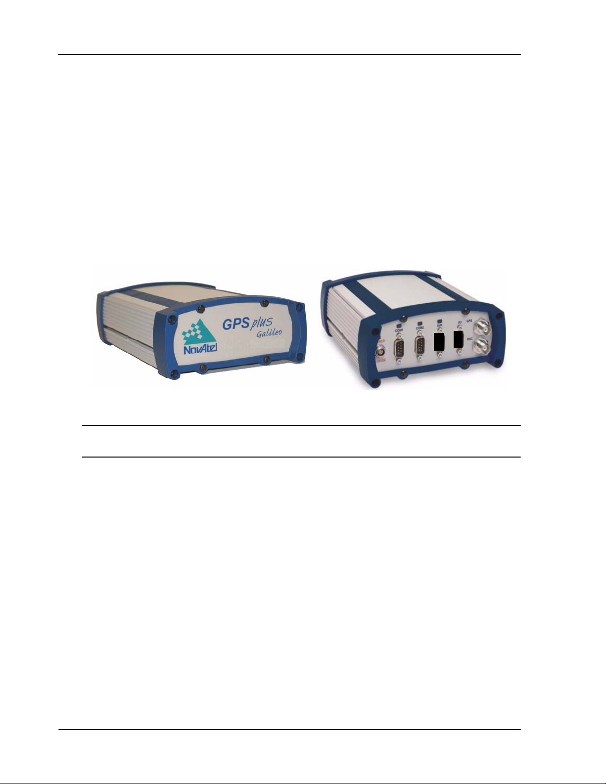
1.4 EuroPak-15a Enclosure
The EuroPak-15a provides a hardware interface between your equipment and the NovAtel Euro-L1E5a card.
Each is a rugged, sealed enclosure that provides protection against adverse environments. It has DB-9
connectors to access data and status signals.
The EuroPak-15a offers the following features:
• A mounting enclosure with a PCB interconnect back plane
• Two serial ports provided on two DB-9P connectors (see the note below):
•COM1
• COM3 (the port is labelled COM2 on the enclosure but is COM3 in the software)
• Auxiliary status and synchronization signals
EuroPak-15a Receiver User Manual Rev 5 19
Page 20
Chapter 1 Introduction
• Antenna or signal generator Radio Frequency (RF) ports
• Input power port
• Indicators to provide power and communication status
• An external oscillator port (input only)
The following accessories are included with the EuroPak-15a:
• 1 12V power adapter cable
• 1 I/O cable
• 1 null modem serial cable
• 1 straight through serial cable
• A CD containing NovAtel’s PC utilities and product documentation
For technical specifications on the EuroPak-15a, please see Appendix A, Technical Specifications starting on
Page 110.
Figure 2: EuroPak-15a Enclosure
The port labelled COM2 on the back of the receiver, see Figure 2 above, connects to COM3 of the internal
Euro-L1E5a card.
1.5 EuroPak-15a Features
The EuroPak-15a has been designed with the following features:
• 16 channel parallel tracking
• Fully field-upgradeable firm ware
• Low power consumption
• 1 Hz raw data and position output rates
At a minimum, the following channel configuration is available:
• 8 GPS L1 (for L1L5GPS model)
• 8 GPS L5 (for L1L5GPS model)
• 5 Galileo L1 (for L1E5aGAL model)
• 5 Galileo E5a (for L1E5aGAL model)
• 6 GPS L1 (for L1E5aGAL model)
20 EuroPak-15a Receiver User Manual Rev 5
Page 21

Introduction Chapter 1
Additional features for the receiver card include:
• GEO signal processing
• GPS signal processing
• Galileo signal processing
• Digital pulse blanking for the L1 signal
• Digital pulse blanking for the L5 signal
• Digital pulse blanking for the Galileo L1 signal
• Digital pulse blanking for the Galileo E5a signal
• A variant of the product, the EuroPak-15aT, is available. This variant contains a highly stable
OCXO frequency reference. The EuroPak-15aT can distribute this 10 MHz frequency reference
from its OSC port.
Galileo signal processing will only be available on activated models.
Some of these features are discussed further in the following sections.
1.5.1 GEO Signal Processing
Specific channels have the capability to receive and process the SBAS signal provided by GEOs. These signals
are in-band at L1 and L5. They are identified through the use of SBAS-specific PRN numbers. The SBAS
message is decoded and separated into its various components. The SBAS message and associated
pseudorange are provided as an output.
1.5.2 Digital Pulse Blanking
Digital pulse blanking involves removing or attenuating pulses in the RF signal that exceed a specified level.
The EuroPak-15a provides digital pulse blanking for the GPS L1, GPS L5 signal, Galileo L1 and Galileo E5a
signal paths. Digital pulse blanking reduces the negative effects of pulsed interference.
Use the PULSEBLANKING command to enable/disable pulse blanking or control its sensitivity, see Page 62.
1.6 Functional Overview
In addition to the EuroPak-15a, an GNSS receiver system typically contains three other major components:
• An antenna (and optional LNA power supply) or signal generator
• A power supply
• Data communications equipment
1.7 Internal Euro-L1E5a Card
The internal Euro-L1E5a card consists of a radio frequency and a digital electronics section.
1.7.1 Radio Frequency Section
The receiver obtains a filtered and amplified L1, L5 or E5a signal from the antenna or signal generator via the
coaxial cable. The RF section performs the translation from the incoming RF signal to an IF signal usable by
the digital section. It also supplies power to the active antenna’s LNA through the coaxial cable while
EuroPak-15a Receiver User Manual Rev 5 21
Page 22

Chapter 1 Introduction
maintaining isolation between the DC and RF paths. The RF section can reject a high level of potential
interference (for example, MSAT, Inmarsat, cellular phone, and TV sub-harmonic signals).
1.7.2 Digital Electronics Section
The digital section of the receiver receives a down-converted, amplified GNSS signal which it digitizes and
processes to obtain a navigation solution (position, velocity and time). The digital section consists of an analogto-digital converter, a 32-bit system processor, memory, control and configuration logic, signal processing
circuitry, serial peripheral devices, and sup porting circui try.
The digital section performs the translations and calculations necessary to convert the IF analog signals into
usable position and status information. It also handles all I/O functions, in cludi ng the auxiliary strobe signals,
which are described in detail in Section 2.3.1 on Page 26. For input and output levels please see Appendix A,
Technical Specifications on Page 110.
1.8 Antenna or Signal Generator
The purpose of the antenna is to convert the electromagnetic waves transmitted by the satellites into RF signals.
An active antenna or a signal generator is required for the receiver to function properly.
Power for an antenna LNA is supplied by the receiver.
1.9 Principal Power Supply
A single external power supply capable of delivering 15 W is necessary to operate the receiver. See Appendix
A, Technical Specifications starting on Page 110 for details.
WARNING: If the voltage supplied is below the minimum specification, the receiver will suspend
operation. If the voltage supplied is above the maximum specification, the receiver may
be permanently damaged, voiding your warranty.
1.10 Data Communications Equipment
A PC or other data communications equipment is necessary to communicate with the receiver and, if desired, to
store data generated by the receiver.
22 EuroPak-15a Receiver User Manual Rev 5
Page 23

Chapter 2 Installation
This chapter contains instructions and tips to set up your NovAtel receiver to create a GNSS receiver system.
At the time of publication, it is recommended that the L5 signal for the receiver be generated by a signal
generator as there are no L5 signals in space.
2.1 Additional Equipment Required
In order for the receiver to perform optimally, the following additional equipment is required:
• An interface for power, communications, and other signals
• An antenna or signal generator
• A quality coaxial cable (and interconnect adapter cable as necessary)
• Data communications equipment capable of serial communications
• A serial cable (if not included with the receiver)
• A power supply
• A power cable (if not included with the receiver)
CAUTION:When the EuroPak-15a receiver is installed in a permanent location, such as in a
building, it should be prot ected by a lightening protection device according to local
building codes. See also Warranty Policy on Page 13.
2.1.1 Selecting an Antenna or Signal Generator
An L5 Signal Generator is available from NovAtel, see the A viation Group’ s contact information on Page 14 to
learn more.
The GPS-704-X antenna is a wide band passive antenna available from NovAtel. It is designed to operate in the
frequency range 1150-1650 MHz. An external LNA is required.
NovAtel offers a variety of antenna models. Each offer exceptional phase-center stability , a significant measure
of immunity against multipath interference and has an environmentally-sealed radome.
Connection at the time of publication is directly to a signal generator. There are no L5 signals in space at
the present time.
2.1.2 Choosing a Coaxial Cable
An appropriate coaxial cable is one that is matched to the impedance of the antenna or signal generator and
receiver being used (50 ohms), and whose line loss does not exceed 10.0 dB. If the limit is exceeded, excessive
signal degradation will occur and the receiver may not be able to meet its performance specifications. NovAtel
offers a variety of coaxial cables to meet your interconnection requirements, including:
• 5, 15, or 30 m RF cables with TNC male connectors on both ends (NovAtel part numbers C006, C016
and C032 respectively)
Your local NovAtel dealer can advise you about your specific configuration. Should your application require
the use of cable longer than 30 m you will find the application note RF Equipment Selection and Installation at
our website, www.novatel.com
, or you may obtain it from NovAtel Customer Service directly.
High-quality coaxial cables should be used because a mismatch in impedance, possible with lower quality
cable, produces reflections in the cable that increase signal loss. Though it is possible to use other high-quality
RF cables, the performance specifications of the EuroPak-15a receivers are warranted only when used with
EuroPak-15a Receiver User Manual Rev 5 23
Page 24

Chapter 2 Installation
NovAtel-supplied accessories.
2.1.3 Power Supply Requirements
This section contains information on the requirements for the input power to the receiver. See Appendix A,
Technical Specifications starting on Page 110 for more power supply specifications.
WARNING: If the voltage supplied is below the minimum specification, the receiver will suspend
operation. If the voltage supplied is above the maximum specification, the receiver may
be permanently damaged, voiding your warranty.
The receiver is designed to prevent internal damage when subjected to a reverse polarity power connection. It
also provides protection from short over voltage events. It is recommended that appropriate fuses or current
limiting be incorporated as a safety precaution on all power lines used. Use a sufficient gauge of wire to ensure
that the voltage at the connector is within the receiver’s requirements.
2.1.3.1 EuroPak-15a Enclosure
The EuroPak-15a is supplied with a 12 V power adapter with a built-in slow-blow fuse for use with a standard
12 VDC power outlet.
If a different supply is desired, the input range required is +9 to +18 VDC. The type of connector required to
mate with the receiver’s power connector is a 4-pin LEMO socket connector labelled PWR. The supply should
be capable of 15 W. See Appendix D, Replacement Parts starting on Page 126 for the LEMO connector part
number.
2.2 Installation Overview
Once you have selected the appropriate equipment, complete the following steps to set up and begin using your
NovAtel receiver.
1. Mount the antenna or signal generator to a secure, stable structure, see Section 2.2.1 on Page 25.
2. Connect the antenna or signal generator to the receiver with an RF cable, using the information
given in Section 2.2.2 on Page 25.
3. Apply power to the receiver, as described in Section 2.2.3 on Page 26.
4. Connect the receiver to a PC or other data communications equipment by following the
information given in Section 2.2.4 on Page 26.
Figure 3 on the next page shows a typical set up for an enclosed receiver.
24 EuroPak-15a Receiver User Manual Rev 5
Page 25
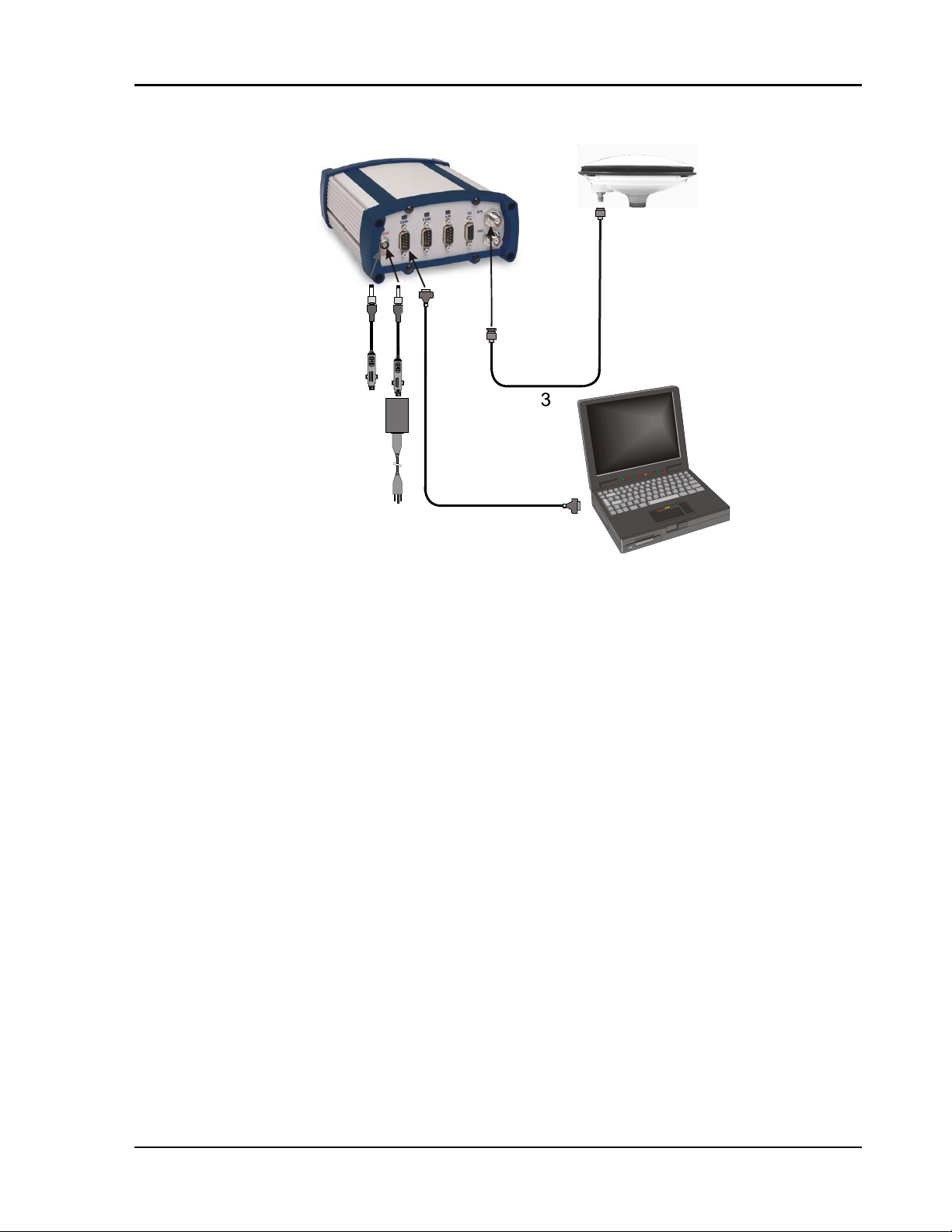
Installation Chapter 2
1
2
5
4
7
6
Figure 3: Typical Receiver Installation
Reference Description
1 Receiver
2 Antenna or Signal Generator
3RF Cable
412V Power Cable
5 12V Power Cable with Optional AC Adapter or Aircraft Power Conditione r
6 Null Modem Data Cable
7 Data Communications Equipment
2.2.1 Mounting the Antenna or Signal Generator
When installing an antenna or signal generator system:
• Mount the antenna on a secure, stable structure capable of safe operation in the specific
environment
Also, if mounting an antenna:
• Choose an antenna location that has a clear view of the sky so that each satellite above the horizon
can be tracked without obstruction
2.2.2 Connecting the Antenna or Signal Generator to the Receiver
Connect the antenna or signal generator to the receiver using high-quality coaxial cable, as discussed in Section
2.1.2 on Page 23.
The EuroPak-15a provides a TNC female connector, which can be connected to the antenna or signal generator
directly with any of NovAtel’s coaxial cables.
EuroPak-15a Receiver User Manual Rev 5 25
Page 26

Chapter 2 Installation
2.2.3 Applying Power to the Receiver
Connect the power supply to the PWR port of the EuroPak-15a receiver.
2.2.4 Connecting Data Communications Equipment
In order to communicate with the receiver by sending commands and obtaining logs, a connection to some
form of data communications equipment is required. The default configuration available for each of the
receiver types is given in the table below. Consult NovAtel Customer Service for more details on factory
configuration. See Appendix A, Technical Specifications starting on Page 110 for data connection details.
Table 1: Default Serial Port Configurations
Receiver COM1 COM2
EuroPak-15a RS-232 RS-232
Each port supports some, or all, of the following signals:
• Clear To Send (CTS)
• Transmitted Data (TXD)
• Request To Send (RTS)
• Received Data (RXD)
The EuroPak-15a enclosure is Data Terminal Equipment (DTE) so that TXD and RTS are outputs while RXD
and CTS are inputs. A null modem cable is required to connect to another DTE like a terminal or a PC.
2.3 Additional Features and Information
This section contains information on the additional features of the EuroPak-15a receivers, which may affect the
overall design of your receiver system.
2.3.1 Strobes
A set of inputs and outputs that provide status and synchronization signals are given on the EuroPak-15a. These
signals are referred to as strobes. As shown in Table 2 on Page 27, not all strobe signals are provided on all
receivers. However, for those products for which strobes are available, you may want to design your
installation to include support for these signals.
The EuroPak-15a enclosure provides strobe signals at its I/O port, as described in Table 54 on Page 114.
Strobe signals include an input and several outputs as described below:
• Mark Input (Event1) A pulse on this input triggers certain logs to be generated.
(see Section 4.2.2, Log Triggers on Page 34).
• Measure Output (MSR) Falling edge is synchronized with internal GPS
measurements.
• Pulse Per Second Output (PPS) A pulse for which the falling edge is synchronized with GPS
time.
• Position Valid Output (PV) High when good GPS position and time solution.
• Error Output (ERROR) High when a receiver hardware failure is detected.
See Appendix A, Technical Specifications starting on Page 110, for further inf ormation on the strobe signal
characteristics.
26 EuroPak-15a Receiver User Manual Rev 5
Page 27

Installation Chapter 2
Table 2: Available Strobe Signals on the EuroPak-15a
Signal EVENT1 MSR PPS PV
EuroPak-15a I/O port,
pin 4
I/O port,
pin 3
I/O port,
pin 2
I/O port,
pin 5
ERROR
I/O port,
pin 8
STATUS
_RED
Not
available
Not
available
The ground return pin for these signals is Pin 9.
2.3.2 Status Indicators
The EuroPak-15a receivers have LED indicators that provide the status of the receiver. The EuroPak-15a
provides the status indicators shown in Table 3.
Table 3: EuroPak- 15 a Status Indicators
Indicator Indicato r Color Status
COM1
COM2
PWR Red The receiver is powered
Green Data is being transmitted from COM1
Red Data is being received on COM1
Green Data is being transmitted from COM3
Red Data is being received on COM3
2.3.3 External Oscillator
You may connect an external oscillator to a EuroPak-15a model, without an internal oven-controlled
crystal oscillator (OCXO) as explained in this section. On the EuroPak-15aT model, the OSC port is for
output from the internal OCXO only, and therefore this section does not apply to it.
STATUS
_GREEN
For certain applications requiring greater precision than what is possible using the on-board 20 MHz, voltagecontrolled, temperature-compensated crystal oscillator (VCTCXO), you may wish to connect the EuroPak-15a
to an external, high-stability oscillator. The external oscillator can be either 5 MHz or 10 MHz.
If you do not use the EXTERNALCLOCK command to specify a clock type, see Page 54, it s default is
DISABLED. This means the external clock input is off and the board is using the on-board VCTCXO.
Installation consists of connecting a cable from the external oscillator to the EuroPak-15a’s external oscillator
input connector.
The BNC external oscillator port, labelled OSC, is used for input signals on the EuroPak-15a and for output
signals on the EuroPak-15aT. See Figure 2 on Page 20.
Once the external oscillator has been installed, the EXTERNALCLOCK command, see Page 54, must be
issued to define the clock model (for example, cesium, rubidium or ovenized crystal). If the input clock rate is
5 MHz, the EXTERNALCLOCK command must be issued to change the 10 MHz default rate.
2.3.4 Mounting Bracket
Along with the EuroPak-15a enclosure, mounting kits have been provided to facilitate mounting the receivers
to a surface. To install the mounting bracket provided with the EuroPak-15a, refer to the instructions provided
with the mounting kit. Page 119 provides the dimension information for the bracket.
The mounting kits are not designed for use in high-dynamics/vibration environments. Contact NovAtel,
see Page 14, if your application requires the EuroPak-15a to be mounted in these types of environments.
EuroPak-15a Receiver User Manual Rev 5 27
Page 28

Chapter 3 Operation
Before operating the EuroPak-15a for the first time, ensure that you have followed the installation instructions
in Chapter 2. From here on, it will be assumed that testing and operation of the EuroPak- 15a will be perform ed
while using a personal computer (PC), which allows the greatest ease and versatility.
3.1 Pre-Start Check List
Before turning on power to the EuroPak-15a, ensure that all of the following conditions have been met:
• T he an tenna or signal generator is properly installed, powered, and connected
• T he PC is pro perly connected using a serial cable, and its communications protocol has been
configured to match that of the EuroPak-15a
Supply power to the EuroPak-15a only after all of the above checks have been made. Note that the warm-up
process may take several minutes, depending on ambient temperature.
3.2 Start-Up
The EuroPak-15a’s firmware resides in non-volatile memory . After supplying power to the unit, wait a moment
for self-boot, and the EuroPak-15a will be ready for command input.
The initial start-up indicator to let you know that the EuroPak-15a's main serial port is ready to communicate:
• Your PC will display the following prompt, indicating you are connected through the COM1 port:
[COM1]
The receiver has 4 modes of operation including power-up mode:
•Power-Up
• Operational
•Fault
• Maintenance
The EuroPak-15a is in power-up mode after receiving a reset signal. While in this mode, everything is disabled
except for the clock generators and microprocessor interface. During this mode, Firmware (FW) is transferred
from Flash to RAM, the 32-bit CRC is verified on the FW load and the Initiated Built In Test (IBIT) is
exercised to determine whether the receiver is usable. This mode ends when the functional blocks of the
receiver have been enabled, initialized and the IBIT has been successfully executed.
The EuroPak-15a is in operational mode following power-up mode and before a fault is discovered by the
Continuous Built In Test (CBIT) and goes into fault mode when the device outputs are affected by one or more
faults preventing its use.
The EuroPak-15a is in maintenance mode when it is loading firmware. Maintenance mode can only be entered
via the Power-up mode.
Once you are connected, commands can be entered as explained in Section 3.3, Communicating with the
EuroPak-15a on Page 29.
28 EuroPak-15a Receiver User Manual Rev 5
Page 29
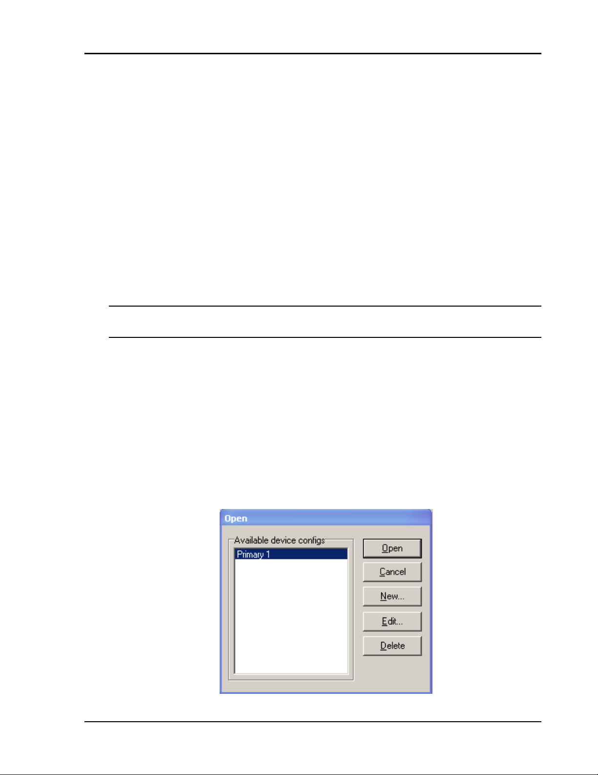
Operation Chapter 3
3.3 Communicating with the EuroPak-15a
Communication with the receiver consists of issuing commands through the com munication ports from an
external serial communications device. This could be either a PC or laptop that is directly connected to the
receiver serial port using a null modem cable.
The commands and logs used by the EuroPak-15a, as well as the fields within them, follow specific formats,
which are discussed in Chapter 4. The valid commands, which are used to control the operation and data
logging of the EuroPak-15a, are specified in Chapter 5. Chapter 6 provides details on the data logs that can be
requested from the EuroPak-15a. It is to your advantage to become thoroughly familiar with Chapters 4
through 6 of this manual to ensure maximum utilization of the EuroPak-15a's capabilities.
3.4 Getting Started
Included with your receiver are NovAtel’s GPSolution (Aviation) and Convert programs. GPSolution
(Aviation) is a Microsoft Windows-based GUI which allows you to access the receiver's many features without
the need for communications protocol or to write special software. The Convert utility is a Windows-based
utility that allows you to convert between file formats, and strips unwanted records for data file compilation.
See the EuroPak-15a Quick Start Guide for more information on their installation.
You must install the Aviation version of the PC Utilities provided on your CD. It is only this version,
GPSolution (Aviation), of GPSolution that works with the EuroPak-15a receiver.
3.4.1 Starting the Receiver
The receiver’s software resides in read-only memory. When first powered, it undergoes a complete self-test. If
an error condition is detected during a self-test, the self-test status word changes. This self-test status word can
be viewed in the header of any data output log. See also Chapter 8, Built-In Status Test starting on Page 107.
3.4.2 Communicating with the Receiver Using GPSolution (Aviation)
Launch the GPSolution (Aviation) program and select Device | Open from its main menu. The Open dialog
appears. The example below shows an Open dialog with a possible configurations already set up. Your
configurations may be different or you may have none at all. In that case, the Available device configs window
would be empty.
EuroPak-15a Receiver User Manual Rev 5 29
Page 30

Chapter 3 Operation
Refer to GPSolution (Aviation)’s Help file by selecting Help | Contents from the main menu to see Help for
windows and their descriptions. Ensure you can see the Console and ASCII Messages windows by selecting
them under View in the main menu.
When the receiver is first turned on, no data is transmitted from the COM ports except for the port prompt. The
Console window displays a port name:
[COM1] if connected to COM1 port,
or
[COM3] if connected to COM3 port
Any of the above prompts indicate that the receiver is ready and waiting for command input.
If you find that GPSolution (Aviation) is unable to locate your EuroPak-15a receiver, it may be that you
have previously used the SAVECONFIG command. In this case, try using a different COM port to
communicate to the receiver. Once communication has been established, issue a FRESET STANDARD
command. You should now be able to use your original communication port again.
WARNING!: Ensure all other windows are closed in GPSolution (Aviation) when entering the
SAVECONFIG command in the Console window.
Commands are typed at the interfacing computing device’s keypad or keyboard, and executed after issuing a
carriage return command which is usually the same as pressing the <Enter> key.
An example of a response to an input command is the FIX POSITION command. It can be entered like this:
[COM2] fix position 51.11635 -114.0383 1048.2 [carriage return]
<OK
where
[COM2] is the port prompt, the bolded type is the command you enter from you keypad or
keyboard and [carriage return] indicates that you should press the <Enter> key.
The above example illustrates command input to the base receiver’s COM2 port which sets the position of the
base station receiver for differential operation. Confirmation that the command was actually accepted is the
appearance of <OK.
If a command is entered incorrectly, the receiver responds with:
<I
NVALID MESSAGE ID (or a more detailed message)
WARNING!: Ensure the Control Panel’s Power Settings on your PC are not set to go into Hibernate
or Standby modes. Data will be lost if one of these modes occurs during a logging session.
30 EuroPak-15a Receiver User Manual Rev 5
Page 31

Chapter 4 Using Commands and Logs
Chapter 5 and Chapter 6 provide the details of the commands and logs used to communicate with the EuroPak15a. The sections below give information on using these messages, including the formats they can take and the
responses they may provide.
4.1 Entering Commands
The EuroPak-15a is capable of responding to many different input commands. The commands offer a wide
range of flexibility and can be used to control the following:
• The overall status of the Eu roPak-15a
• Input and output functions
• Configuration of a specific channel of the EuroPak-15a
The following rules apply when entering commands and logs:
1. You must enter comman ds in Abbreviated ASCII format. The name of the command and its
parameters are entered.
2. The commands are not case sensitive. For example:
FIX POSITION or fix position
3. At the end of a command or command string, press <ENTER>.
4.1.1 Command Settings on Power-Up
When the receiver is first powered up, or after an FRESET command, all commands revert to the factory
default settings.
The FRESET command causes all previously stored information saved to non-volatile memory to be
erased. This command is detailed in Section 5.3.9 on Page 58.
4.1.1.1 Factory Defaults
The factory defaults for the EuroPak-15aT timing model are:
ANTENNAPOWER ON
CLOCKADJUST DISABLE
COM COM1 9600 N 8 1 N OFF ON
COM COM3 115200 N 8 1 N OFF ON
POSITIONTYPE GPSL1
SDLLBW n 0.2 where n is for channel numbers 0 to 15 inclusive
SPLLBW n 3.0 where n is for channel numbers 0 to 15 inclusive
EXTERNALCLOCK OCXO 10 MHZ
The factory defaults for the EuroPak-15a non-timing model are:
ANTENNAPOWER ON
CLOCKADJUST ENABLE
COM COM1 9600 N 8 1 N OFF ON
COM COM3 115200 N 8 1 N OFF ON
EuroPak-15a Receiver User Manual Rev 5 31
Page 32

Chapter 4 Using Commands and Logs
POSITIONTYPE GPSL1
SDLLBW n 0.2 where n is for channel numbers 0 to 15 inclusive
SPLLBW n 15.0 where n is for channel numbers 0 to 15 inclusive
EXTERNALCLOCK DISABLE
4.1.1.2 Default Thresholds
For L1 GPS, L1 WAAS and L1 Galileo, the acquistion threshold is 38 dB-Hz, the tracking threhold is 22 dB-Hz
and the cross-correlation threshold is 36 dB-Hz.
For L5 GPS, L5 WAAS and E5a Galileo, the acquistion threshold is 36 dB-Hz, the tracking threhold is 22 dBHz and the cross-correlation threshold is 36 dB-Hz.
4.1.1.3 Default AGC Modes
The AGC modes are set to
AUTO by default for all frequencies.
4.1.2 Determining the Current Command Settings
T o determine the current command settings of a receiver , request an RXCOMMANDS log, which is described in
Section 6.3.8 on Page 88. This will provide a listing of all commands and their parameter settings. This log
provides the most complete information on receiver configuration.
For some commands, including COM and LOG, multiple parameter sets can exist. For exam ple, the LOG
command can be entered with one set of parameters to enable logging of the PSRPOS log. It can then be
entered again with a second set of parameters to configure the EuroPak-15a to capture the RANGE log. When
the LOG command is entered the second time, the new parameter set does not overwrite the first, it exists in
addition to the first set.
4.1.3 Response Formats
The format of the response is dependent on the format of the input command. If the command is input as
Abbreviated ASCII, the output will be Abbreviated ASCII.
The Abbreviated ASCII response consists of a leading < followed by the response string, like the example
below:
<OK
4.1.4 Response Messages
The receiver is capable of outputting several responses for various conditions. Most of these responses are error
messages to indicate when something is not correct. Table 4 on Page 33 outlines the various response strings
and message IDs.
32 EuroPak-15a Receiver User Manual Rev 5
Page 33

Using Commands and Logs Chapter 4
Table 4: Response Messages
String ID
OK 1 Command was received correctly
NOT ENOUGH RESOURCES IN
SYSTEM
DATA PACKET DOESN’T VERIFY 4 Data packet is not verified
COMMAND FAILED ON RECEIVER 5 Command did not succeed in accomplishing requested task
INVALID MESSAGE ID 6 The input message ID is not valid
INVALID MESSAGE FIELD = X 7 Field x of the input message is not correct
MESSAGE MISSING FIELD 9 A field is missing from the input message
ARRAY SIZE FOR FIELD X EXCEEDS
MAX
PARAMETER X IS OUT OF RANGE 11 Field x of the input message is outside the acceptable limits
TRIGGER X NOT VALID FOR THIS LOG 14 Input trigger x is not valid for this type of log
NO VALID AUTH CODE FOR THAT
MODEL
CHANNEL IS INVALID 20 The channel number is not correct
REQUESTED RATE IS INVALID 21 The requested rate is invalid
CHANNELS LOCKED DUE TO ERROR 23 Channels are locked due to error
The request has exceeded a limit (for example, the
3
maximum number of logs are being generated)
10 Field x contains more array elements than allowed
19 The model attached to the authcode is not valid
Meaning
INJECTED TIME INVALID 24 Injected time is invalid
COM PORT NOT SUPPORTED 25 The COM port is not supported
MESSAGE IS INCORRECT 26 The message is invalid
INVALID PRN 27 The PRN is invalid
MESSAGE TIMED OUT 31 The message has timed out
UNKNOWN COM PORT REQUESTED 33 Unkno wn COM port requested
HEX STRING NOT FORMATTED
CORRECTLY
INVALID BAUD RATE 35 The baud rate is invalid
MESSAGE IS INVALID FOR THIS
MODEL
COMMAND ONLY VALID IF IN NVM
FAIL MODE
INVALID OFFSET 41 The offset is invalid
MAX NUMBER OF USER MESSAGES
REACHED
GPS PRECISE TIME IS ALREADY
KNOWN
34 Hex string not formatted correctly
36 This message is invalid for this model of receiver
40 Comm and is onl y valid if NVM is in fail mode
The maximum number of user messages allowed has been
78
reached
84 GPS precise time is already known
EuroPak-15a Receiver User Manual Rev 5 33
Page 34

Chapter 4 Using Commands and Logs
4.2 Logging Data
You can control how the EuroPak-15a logs data by using the LOG comm and given on Page 59. A field within
this command allows you to specify which data log from Chapter 6 to capture. Note the following however:
1. The EuroPak-15a can handle 20 logs at a time. If you attempt to log more than 20 logs at a time,
the receiver will respond with the error message:
Not enough resources in system
2. Maximum flexibility for logging data is provided to you by these logs. You are cautioned,
however, to recognize that each log requested requires additional CPU time and memory buffer
space. Too many logs may result in lost data and degraded CPU performance. Receiver overload
can be monitored using the idle-time field and the buffer overrun bits of the Receiver Status field,
which are both found in any log header.
When a log is generated, it is sent to the serial port specified by the port parameter in the entered LOG
command.
4.2.1 Log Types
The receiver is capable of generating many different logs. These logs are divided into the following three types:
• Synchronous The data contained in synchronous logs is generated on a regular schedule.
• Asynchronous The data in asynchronous logs is generated at irregular intervals. If these logs
were collected on a regular schedule, there would be a delay in capturing the
new data. The result is that changes to the data are not captured the moment
they were available.
• Polled The data in polled logs is generated only when requested. Typically the data
in these logs, such as configuration settings, does not change.
4.2.2 Log Triggers
Each log can be configured for output when a certain condition, or trigger, is met. The possible triggers are:
• ONNEW Output a new log whenever the message is updated (not necessarily changed).
• ONCHANGED Output a new log whenever the message has changed.
• ONTIME Output a new log at a specified interval (in seconds).
• ONCE Output the current, existing message. Only a single log will be generated.
For each log type described in Section 4.2.1, Log Types only certain triggers are valid. For example, the
VERSION log is a polled log because it does not change. Therefore, it would not make sense to log this kind of
data using the ONCHANGED or ONNEW triggers. Table 5 outlines the valid triggers for each log type:
Table 5: Log Triggers for Each Log Type
Type
Recommended Triggers Illegal Triggers
Synchronous ONTIME
Asynchronous ONCHANGED -
Polled ONCE
34 EuroPak-15a Receiver User Manual Rev 5
ONNEW
ONCHANGED
ONNEW
ONCHANGED
Page 35

Using Commands and Logs Chapter 4
4.2.3 Specifying Log Formats
Logs can be requested in two formats, ASCII or Binary, described in Section 4.3 on Page 35.
When entering the LOG command using ASCII format, the default format for the output log is ASCII. To
generate logs in a different format, a suffix is added to the name of the message being requested. To request a
log in ASCII format, add A to the end of the log as shown below.
LOG ALMANACA
To request a log in Binary format, B is added to the end of the log name.
LOG RANGEB ONTIME 30
When issuing Binary logs, the output message type is set in the Message Type field in the command header, as
described in Table 7 on Page 37.
4.3 Log Formats
The receiver handles all incoming and outgoing NovAtel logs using two different formats:
•ASCII
•Binary
This allows for some versatility in the way the EuroPak-15a can be used.
4.3.1 ASCII
The ASCII format is readable by both you and a computer. The structures of all ASCII messages follow the
general conventions as noted here:
1. Basic format:
#HEADER_PARAMS;PARAM_1,PARAM_2,...,PARAM_N* XXXXXXXX [CR][LF]
2. The lead code identifier for each record is '#'. This identifier is followed by the header parameters,
as described in Table 6 on Page 36.
3. Each log is of variable length depending on the amount of data and field formats.
4. All data fields are delimited by a comma ',' with two exceptions. The first exception is the last
header field which is followed by a ';' to denote the start of the data message. The other exception
is the last data field, which is followed by a '*' to indicate end of message data.
5. Each log ends with a hexadecimal number preceded by an asterisk and followed by a line
termination using the carriage return and line feed characters, for example,
*1234ABCD[CR][LF]. This value is a 32-bit cyclic redundancy check (CRC) of all bytes in the
message, excluding the '#' identifier and the asterisk preceding the checksum digits. See Section
4.4.2.5 on Page 41 for the algorithm used to generate the CRC.
6. An ASCII string is one field and is surrounded by double quotation marks, for example, “ASCII
string”. If separators are surrounded by quotation marks then the string is still one field and the
separator will be ignored, for example, “xxx,xxx” is one field. Double quotation marks within a
string are not allowed.
7. If the receiver detects an error parsing an input message, it will return an error response message.
Please see Section 4.1.4 on Page 32 for a list of response messages from the receiver.
EuroPak-15a Receiver User Manual Rev 5 35
Page 36

Chapter 4 Using Commands and Logs
The ASCII message header is formatted as follows:
Table 6: ASCII Message Header Structure
Field
1 sync Char
2 message Char
3 port Char
4 Reserved ULong Reserved for internal use N
5 idle time Float The minimum percentage of time that the processor is idle Y
6 time status Enum
7 week ULong G PS week number Y
8 seconds GPSec
9
10
11 ULong Y
12 ; Char The ‘;’ character indicates the end of the header N
Field
Name
receiver
status
Reserved
Field
Type
ULong
ULong
Description
Sync character. The ASCII message is always preceded by a
single ‘#’ symbol.
The ASCII name of the message. The names of logs are given
in Table 34 on Page 71.
The name of the port from which the log was generated.
See Table 10 on Page 39.
The quality of the GPS time, as described i n Section 4.4.2.4
on Page 40.
Seconds from the beginning of the GPS week accurate to the
millisecond level
An eight digit hexadecimal number representing the status of
various hardware and firmware components of the receiver.
This number is described in Table 46 on Page 93.
Reserved for internal use
Ignored
on Input
N
N
Y
Y
Y
Y
Y
Example ASCII Format Log:
#PSRPOSA,COM1,0,43.0,FINESTEERING,265,320943.000,00840000,
0000,33331;SOL_COMPUTED,SINGLE,51.11638529847,-114.03825624352,
1045.2359,0.0000,WGS84,1.5908,1.4096,2.3924,"",0.000,0.000,10,8,
0,0,0,0,0,0*84ea7b68[CR][LF]
4.3.2 Binary
Binary messages are meant strictly as a machine readable format. They are also ideal for applications where the
amount of data being transmitted is fairly high. Because of the inherent compactness of binary as opposed to
ASCII data, the messages are much smaller. This allows a larger amount of data to be transmitted and received
by the receiver’s communication ports. The structure of all Binary format messages follows the general
conventions as noted here:
1. Basic format:
Header 3 sync bytes plus 25 bytes of header information. The header length is variable
as fields may be appended in the future. Always check the header length.
Parameters Variable length binary data
CRC 4 bytes
2. The 3 Sync bytes are always:
36 EuroPak-15a Receiver User Manual Rev 5
Page 37

Using Commands and Logs Chapter 4
Byte Hex Decimal
First AA 170
Second 44 68
Third 12 18
3. The CRC is a 32-bit cyclic redundancy check performed on all data including the header. See
Section 4.4.2.5 on Page 41 for the CRC algorithm.
4. The header is in the format shown in Table 7 on Page 37.
Table 7: Binary Message Header Structure
Field
Field
Name
Field
Type
Description
Binary
Bytes
Binary
Offset
Ignored
on Input
1 sync Char Hexadecimal 0xAA 1 0 N
2 sync Char Hexadecimal 0x44 1 1 N
3 sync Char Hexadecimal 0x12 1 2 N
header
4
5
6
7
8
length
message
ID
message
type
port
address
message
length
UChar Length of the header 1 3 N
UShort
Char
Char
UShort
Message ID. The message IDs for logs are given in
Table 34 on Page 71.
Message type indicator, as explained in Section
4.2.1 on Page 34.
The port from which the log was generated.
See Table 10 on Page 39.
The length in bytes of the body of the message. This
does not include the header nor the CRC.
2 4 N
1 6 N
1 7 N
2 8 N
For multiple related logs. A number that counts
down from N-1 to 0 where N is the number of
9 sequence UShort
related logs and 0 means it is the last one of the set.
2 10 N
Most logs only come out one at a time in which case
this number is 0.
The percentage of time that the processor is idle in
10 idle time Char
the last second. Take the time (0-200) and divide by
1 12 Y
two to give the percentage of time (0-100%).
11 time status Enum
The quality of the GPS time, as described in Section
4.4.2.4 on Page 40
a
1
13
12 week UShort GPS week number 2 14
milli-
13
seconds
receiver
14
status
15
Reserved
16 UShort 2 26 Y
a. This ENUM is not 4 bytes long but, as indicated in the table, is only 1 byte.
b. These time fields are ignored if Field #11, Time Status, is invalid. In this case the current receiver time is used. The
recommended values for the three time fields are 0, 0, 0.
GPSec Milliseconds from the beginning of the GPS week 4 16
32 bits representing the status of various hardware
ULong
and firmware components of the receiver. This
4 20 Y
number is described in Table 46 on Page 93.
UShort
Reserved for internal use
2 24 Y
N
N
N
b
b
b
EuroPak-15a Receiver User Manual Rev 5 37
Page 38

Chapter 4 Using Commands and Logs
4.4 Fields
The commands and logs for the EuroPak-15a use a variety of field types to convey data. The following sections
provide information on the types of fields used and some of the more commonly-used fields.
4.4.1 Field Types
The following table describes the field types used in the commands and logs.
Table 8: Field Types
Type
Char 1
UChar 1
Short 2 A 16-bit signed integer in th e range -32768 to +32767.
UShort 2 A 16-bit unsigned in teger in the range +0 to +65535.
Long 4 A 32-bit signed integer in the range -2147483648 to +2147483647.
ULong 4 A 32-bit unsigned integer in the range +0 to +4294967295.
Double 8
Float 4
Enum 4
GPSec 4
Hex n
String n
Binary Size
(Bytes)
Description
An 8-bit signed integer in the range -128 to +127. This integer value may
be the ASCII code corresponding to the specified character. In ASCII or
Abbreviated ASCII this comes out as an actual character.
An 8-bit unsigned integer. Values are in the range from +0 to +255. In
ASCII or Abbreviated ASCII this comes out as a number.
64 bits, with 1 for the sign, 11 for the exponent, and 52 for the mantissa.
Its range is ±1.7E308 with at least 15 digits of precision. This is IEEE
754.
32 bits, with 1 for the sign, 8 for the exponent, and 23 for the mantissa.
Its range is ±3.4E38 with at least 7 digits of precision. This is IEEE 754.
A 4-byte enumerated type beginning at zero (an unsigned long). In
Binary, the enumerated value is output. In ASCII or Abbreviated ASCII,
the enumeration label is spelled out.
Two separate formats that depend on whether the output is requested in
Binary or an ASCII format. For Binary the output is in milliseconds and
is a long type. For ASCII the output is in seconds and is a float type.
A packed, fixed length (n) array of bytes in Binary but in ASCII or
Abbreviated ASCII is converted into 2 character hexadecimal pairs.
A variable length array of bytes that is null-terminated in the Binary case.
The maximum byte length for the field is shown in the row in the log or
command table.
Section 9 on Page 39 shows the arrangement of bytes within each field type when used by IBM PC computers.
All data sent to or from the receiver, however, is read Least Significant Bit (LSB) first, opposite to what is
shown in Table 9. Data is then stored in the receiver LSB first. For example, in char type data, the LSB is bit 0
and the Most Significant Bit (MSB) is bit 7.
38 EuroPak-15a Receiver User Manual Rev 5
Page 39

Using Commands and Logs Chapter 4
t
t
Table 9: Byte Arra n gem e nts
char
shor
long two's complimen
double S Biased Exponent| 52-bits mantissa
float S Biased Exponent| 23-bits m antissa
70
address n
15 7 0
n + 1 address n
31 23 15 7 0
n + 3 n + 2 n + 1 address n
63 62 52 51 0
n + 7 n + 6 n + 5 n + 4 n + 3 n + 2 n + 1 address n
31 30 23 22 0
n + 3 n + 2 n + 1 address n
4.4.2 Commonly-Used Fields
Some of the more commonly-used fields are discussed in this section.
4.4.2.1 Serial Port Identifiers
The values used to indicate serial ports are given below.
Table 10: Serial Port Identifier Values
ASCII Binary
COM1 32
COM3 96
4.4.2.2 Message Type Indicator
The Message Type Indicator is a byte given in numerous binary format messages and all bin ary headers. It
follows the format in Table 11 below.
Table 11: Message Type Byte Format
Bit Description
0-4 Reserved
Message format, where
00 = Binary
5-6
01 = ASCII
10 = Abbreviated ASCII, NMEA
11 = Reserved
Response indicator, where
0 = original message
7
1 = response message.
(See Section 4.2 on Page 34 for more
information on logging data.)
EuroPak-15a Receiver User Manual Rev 5 39
Page 40

Chapter 4 Using Commands and Logs
4.4.2.3 Message Time Stamps
All NovAtel format messages generated by the receiver have a GPS time stamp in their header. GPS time is
referenced to UTC with zero point defined as midn ig ht on the ni ght of Ja nuar y 6, 19 80 at 0:00 hou rs. The tim e
stamp consists of the number of weeks since that zero point, the EuroPak-15a rolls over, (0 to 1023) and the
number of seconds since the last week number change (0 to 603,799). GPS time differs from UTC time since
leap seconds are occasionally inserted into UTC but GPS time is continuous. In addition a small error (less than
1 microsecond) can exist in synchronization between UTC and GPS time. The TIME log reports both GPS and
UTC time and the offset between the two.
The data in synchronous logs, like the RANGE log, are based on a periodic measurement of satellite
pseudoranges. The time stamp on these logs is the receiver estimate of GPS time at the time of the
measurement. When setting time in external equipment, a small synchronous log with a high baud rate will be
accurate to a fraction of a second. A synchronous log with trigger ONTIME 1 can be used in conjunction with
the 1 PPS signal to provide relative accuracy better than 250 ns.
Other log types (asynchronous and polled) are triggered by an external event and the time in the header may not
be synchronized to the current GPS time. Logs that contain satellite broadcast data have the transmit time of
their last subframe in the header. In the header of differential time matched logs, the time of the matched
reference and local observation that they are based on is given. Logs triggered by a mark event have the
estimated GPS time of the mark event in their header. The header of a polled log, like VERSION, gives the
approximate GPS time when its data was generated.
4.4.2.4 GPS Time Status
All reported receiver times are subject to a qualifying time status. This status gives you an indication of how
well a time is known, see Table 12:
Table 12: GPS Time Status
GPS Time Status
(Decimal)
GPS Time Status
(ASCII)
Description
20 UNKNOWN Time validity is unknown.
60 APPROXIMATE Time is set approximately.
100 COARSE This time is valid to coarse precision.
120 COARSESTEERING Time is coarse set, and is being steered.
130 FREEWHEELING
Position is lost, and the range bias cannot be
calculated.
160 FINE Time has fine precision.
180 FINESTEERING Time is fine, set and is being steered.
Time from satellite. This is only used in logs
200 SATTIME
containing satellite data such as ephemeris
and almanac.
There are several distinct states that the receiver will go through:
• UNKNOWN
• COARSE
• FREEWHEELING
• FINE/FINESTEERING
40 EuroPak-15a Receiver User Manual Rev 5
Page 41

Using Commands and Logs Chapter 4
On start up, and before any satellites are being tracked, the receiver can not possibly know the current time. As
such, the receiver time starts counting at GPS week 0 and second 0.0. The time status flag is set to
UNKNOWN.
After the first ephemeris is decoded, the receiver time is set to a resolution of
qualified by the COARSE or COARSESTEERING time status flag depending on the state of the
CLOCKADJUST switch.
Once a position is known and range biases are being calculated, the internal clock model begins modelling the
position range biases and the receiver clock offset.
Modelling continues until the model is a good estimation of the actual receiver clock behavior . At this time, the
receiver time is adjusted again, this time to an accuracy of
time status flag.
The final logical time status flag depends on whether CLOCKADJUST is enabled or not, see Page 50. If
CLOCKADJUST is disabled, the time status flag never improves on FINE. The time is only adjusted again to
within
±1 microsecond if the range bias gets larger than ±250 milliseconds. If CLOCKADJUST is enabled, the
time status flag is set to FINESTEERING and the receiver time is continuously updated (steered) to minimize
the receiver range bias.
If for some reason position is lost and the range bias cannot be calculated, the time status is degraded to
FREEWHEELING.
4.4.2.5 32-Bit CRC
The ASCII and Binary message formats all contain a 32-bit Cyclic Redundancy Check (CRC) for data
verification. This allows you to ensure that the data received (or transmitted) is valid with a high level of
certainty. This CRC can be generated using the C algorithm shown on Page 42.
±1 microsecond. This state is qualified by the FINE
±10 milliseconds. This state is
EuroPak-15a Receiver User Manual Rev 5 41
Page 42

Chapter 4 Using Commands and Logs
#define CRC32_POLYNOMIAL 0xEDB88320L
/* -------------------------------------------------------------------------Calculate a CRC value to be used by CRC calculation functions.
-------------------------------------------------------------------------- */
unsigned long CRC32Value(int i)
{
int j;
unsigned long ulCRC;
ulCRC = i;
for ( j = 8 ; j > 0; j-- )
{
if ( ulCRC & 1 )
ulCRC = ( ulCRC >> 1 ) ^ CRC32_POLYNOMIAL;
else
ulCRC >>= 1;
}
return ulCRC;
}
/* -------------------------------------------------------------------------Calculates the CRC-32 of a block of data all at once
-------------------------------------------------------------------------- */
unsigned long CalculateBlockCRC32(
unsigned long ulCount, /* Number of bytes in the data block */
unsigned char *ucBuffer ) /* Data block */
{
unsigned long ulTemp1;
unsigned long ulTemp2;
unsigned long ulCRC = 0;
while ( ulCount-- != 0 )
{
ulTemp1 = ( ulCRC >> 8 ) & 0x00FFFFFFL;
ulTemp2 = CRC32Value( ((int) ulCRC ^ *ucBuffer++ ) & 0xff );
ulCRC = ulTemp1 ^ ulTemp2;
}
return( ulCRC );
}
42 EuroPak-15a Receiver User Manual Rev 5
Page 43

Chapter 5 Commands
5.1 Functional Listing of Commands
Table 13 lists the commands by function. Please see Section 5.3 on Page 45 for a more detailed description of
each individual command.
Table 13: Commands By Function
Command Description
COMMUNICATIONS, CONTROL AND STATUS
COM
LOG Request a log
UNLOG Remove a specified log from logging control
UNLOGALL Remove all logs from logging control
AGCMODE Control Automatic Gain Cont rol (AGC) functionality
SDLLBW Configure receiver’s DLL filter bandwidth
SPLLBW Configure receiver’s phase-lock-loop bandwidths
RESET Perform a hardware reset
FRESET Reset receiver to factory default
FIX Constrain receiver position
POSITIONTYPE Control the position solution on GPS L1 or L5 signals
SATELLITE TRACKING AND CHANNEL CONTROL
ASSIGN Assign individu al satellite channel
Set serial port configuration
GENERAL RECEIVER CONTROL
POSITION CONTROL
CHANCONFIG Set receiver channel tracking configuration
ECUTOFF Set satellite elevation cut-off angle
PULSEBLANKING
STHRESHOLD Control signal thresholds for acquisition, tracking and cross correlation
UNASSIGN Unassign a previously ASSIGNed channel
CLOCKADJUST
EXTERNALCLOCK
Enable/disable digital pulse blanking for L1 Galileo or E5a signals
CLOCK INFORMATION, STATUS, AND TIME
Enable or disable adjustments to the internal clock and 1PPS output
Set the parameters for an external clock
EuroPak-15a Receiver User Manual Rev 5 43
Page 44

Chapter 5 Commands
5.2 Command Summary
Table 14: Command Summary
Command Name
AGCMODE
ASSIGN
CHANCONFIG
CLOCKADJUST
COM
ECUTOFF
EXTERNALCLOCK
FIX
FRESET
LOG
POSITIONTYPE
Message
ID
229
27
501
15
4
50
230
44
20
1
836
Description Syntax
Control Automatic Gain Control (AGC)
Assign individual satellite channel to a PRN
Set receiver channel tracking configuration
Enable clock adjustments clockadjust switch
Serial port configuration control
Set satellite elevation cutoffs
Set external clock parameters
Fix height, position or velocity
Clear data stored in non-volatile memory.
Followed by a receiver reset.
Request logs from receiver
Set position filter to GPS L1 or L5
frequency
agcmode frequency mode
[pulsewidth loadvalue]
assign channel [state] [prn
[Doppler window]]
chanconfig config
com [port] bps [parity
[databits [stopbits
[handshake [echo [break]]]]]]
ecutoff angle
externalclock clocktype
[freq] [h0 [h1 [h2]]]
fix type [lat lon height]
freset
log [port] message [trigger]
[period [offset] [hold]]
positiontype frequency
PULSEBLANKING
RESET
SDLLBW
SPLLBW
STHRESHOLD
UNASSIGN
UNLOG
UNLOGALL
519
18
800
801
803
29
36
38
Enables or disables digital pulse blanking
for L1 or L5 signals.
Perform a hardware reset
Configure receiver’s DLL filter bandwidth
Configure receiver’s phase-lock-loop bw
Control signal thresholds for acquisition,
tracking and cross correlation
Unassign a previously ASSIGNed channel
Remove log from logging control
Remove all logs from logging control
pulseblanking frequency
switch
reset [delay]
sdllbw dsigchan bw
spllbw psigchan bw
sthreshold sigchan acqui
lock crosscorr
unassign channel
unlog [port] datatype
unlogall [port]
44 EuroPak-15a Receiver User Manual Rev 5
Page 45

Commands Chapter 5
5.3 Command Reference
All syntax strings and command examples given in this section are in the Abbreviated ASCII format, unless
otherwise indicated. The tables provided show the fields necessary for all formats unless otherwise noted.
As mentioned in Section 4.1 on Page 31, all command strings must be followed by <Enter>.
5.3.1 AGCMODE Control Automatic Gain Control
1. This command can fundamentally change the way that the receiver operates. Do not alter the default
settings unless you are confident that you understand the consequences.
2. When the AGC mode is disabled, the Receiver Status word in the message header, discussed in
Table 46, Receiver Status on Page 93, reports the AGC as GOOD as long as the control metric used in
the feedback loop is within 7.5% of the set point.
This command controls the EuroPak-15a’s Automatic Gain Control (AGC) mechanism, which has two primary
functions:
• To perform the analog-to-digital conversions in the receiver’s front end.
• Mitigate jamming.
Table 15: Frequency Values for AGCMODE Command
ASCII Description
L1
L5
L1 GPS and Galileo channels
L5 GPS and E5a Galileo channels
a. Changing GPS L1 affects Galileo L1 and
changing GPS L5 affects Galileo E5a
Table 16: AGC Mode Values
ASCII Description
AUTO
MANUAL
Specifies that the default pulse width
and load values should be used.
Specifies that the values specified in the
pulsewidth and loadvalue fields should
be used.
a
a
EuroPak-15a Receiver User Manual Rev 5 45
Page 46

Chapter 5 Commands
Syntax: Message ID: 229
AGCMODE FREQUENCY MODE [ PULSEWIDTH LOADVALUE ]
Field
1 header
2 frequency See Table 15 on Page 45.
3 mode See Table 16 on Page 45.
4 pulsewidth 35 to 262144
5 loadvalue 35 to 262144
Field
Name
This field contains the Abbreviated ASCII command name. See Section 4.1
on Page 31.
Valid Values
ASCII Binary
Example:
AGCMODE L1 MANUAL 40 50
Description Format
Specifies which signal
type to apply the
command to.
Specifies whether to
use the default or
custom values for the
pulse width and load
value.
Pulse width. A value is
only required when the
mode field is set to
MANUAL.
Modulus load value. A
value is only required
when the mode field is
set to MANUAL.
Binary
Bytes
H 0
Enum 4 H
Enum
Float
Float
4 H+4
4 H+8
4 H+12
Binary
Offset
Table 17: Antispoofing Flag Values
ASCII Description
FALSE Antispoofing is disabled.
TRUE Antispoofing is enabled.
46 EuroPak-15a Receiver User Manual Rev 5
Page 47

Commands Chapter 5
5.3.2 ASSIGN Assign Individual Satellite Channels
The ASSIGN command should only be used by advanced users.
This command may be used to aid in the initial acquisition of a satellite by allowing you to override the
automatic satellite/channel assignment and reacquisition processes with manual instructions. The command
specifies that the selected tracking channel should search for a specified satellite at a specified Doppler
frequency within a specified Doppler window.
The instruction will remain in effect for the specified SV channel and PRN, even if the assigned satellite
subsequently sets. If the satellite Doppler offset of the assigned SV channel exceeds that specified by the
window parameter of the ASSIGN command, the satellite may never be acquired or re-acquired. If a PRN has
been assigned to a channel and the channel is currently tracking that satellite, when the channel is set to AUTO
tracking, the channel will immediately idle and return to automatic mode.
To cancel the effects of ASSIGN, you must issue one of the following:
• The ASSIGN command with the state set to AUTO
• The UNASSIGN command
These will return SV channel control to the automatic search engine immediately.
1. Assigning a PRN to an SV channel does not remove the PRN from the search space of the automatic
searcher; only the SV channel is removed (i.e. the searcher may search and lock onto this PRN on
another channel). The automatic searcher only searches for PRNs 0 to 37 for GPS channels and 0 to 50
for Galileo channels.
2. Assigning an SV channel will set the Channel Assignment bit to 1 for forced assignment in the Channel
Tracking Status field of the RANGE log. The RANGE log is specified in Section 6.3.5 on Page 82.
3. The doppler field applies to L1 GPS and Galileo channels only.
EuroPak-15a Receiver User Manual Rev 5 47
Page 48

Chapter 5 Commands
Syntax: Message ID: 27
ASSIGN CHANNEL [ STATE ] [ PRN [ DOPPLER WINDOW ] ]
Field
1 header
2 channel 0 to 15
3 state See Table 18 below.
4 prn
5 doppler -100 000 to 100 000
Field
Name
Valid Values Description Format
This field contains the Abbreviated ASCII command name. See Section 4.1 on
Page 31.
0 to 37 for GPS
120 to 138 for GEO
0 to 50 for GAL
SV channel number to apply the command
to. 0 is the first SV channel and 15 is the l ast:
16GPSL1L5: 0-7 for GPSL1 and
8-15 for GPSL5
10GALILEO6GPS: 0-9 for GALL1 and
10-15 for GPSL1
See also Section 5.3.3, CHANCONFIG
starting on Page 49 and Table 56 on
Page 120.
Optional desired SV channel state. If a value
is not given, the default of ACTIVE is used.
Optional satellite PRN code. A value is
required only when the state field is set to
ACTIVE.
Optional current L1 Doppler offset of the
satellite specified in the prn field in Hz.
NOTE:Satellite motion, receiver antenna
motion, and receiver clock frequency error
must be included in the calculation of
Doppler frequency.
Binary
Bytes
H 0
ULong 4 H
Enum 4 H+4
Long 4 H+8
Long 4 H+12
Binary
Offset
Error or uncertainty in the L1 Doppler
6 window 0 to 10 000
estimate given in the doppler field, in Hz.
NOTE:This is a ± value. For example, enter
500 for ± 500 Hz.
ULong 4 H+16
Examples:
ASSIGN 0 ACTIVE 37 0 2000
ASSIGN 15 120 -250 0
ASSIGN 11 28 -250 0
The first example sets the first SV channel to acquire satellite PRN 37 in a range from -2000 Hz to +2000 Hz
until the satellite signal has been detected. SV channel 11 is set to acquire satellite PRN 28 at an offset of
-250 Hz only in the third example.
Table 18: Ch an n el State Values
ASCII Description
IDLE Set the SV channel to not track any satellites.
ACTIVE Set the SV channel active.
AUTO Tell the receiver to automatical ly assign PRN codes to channels.
48 EuroPak-15a Receiver User Manual Rev 5
Page 49

Commands Chapter 5
5.3.3 CHANCONFIG
This command changes the channel configuration of the receiver. This will effect the number of channels
tracking GPS signals and the number of channels tracking GEO signals. Entering this command will reset the
receiver, causing the receiver to initiate a cold-start bootup and reset all data stored in NVM to factory default
values (except for the channel configuration).
The default configuration of the L1L5GPS(T) model is 16GPSL1L5 while for the L1E5AGAL(T) model it is
10GALILEO6GPS. If you have a L1E5AGAL(T) model you will also be able to track Galileo and GPS
satellites. If you have an L1L5GPS(T) model you will be able to track GPS but not Galileo satellites.
Syntax: Message ID: 501
CHANCONFIG CONFIG
Field
1 header
2 config See Table 19 below.
Field
Name
Valid Values Description Format
This field contains the Abbreviated ASCII command name. See
Section 4.1 on Page 31.
Example:
CHANCONFIG 16GPSL1L5
ASCII Description
16GPSL1L5 8 GPS L1 + 8 GPS L5 channels
10GALILEO6GPS 5 Galileo L1 + 5 Galileo E5a + 6 GPS L1 channels
10GALILEODATA6GPS
16GALILEOL1E5a 8 Galileo L1 + 8 Galileo E5a channels
8GPS8GEO 8 GPS L1 + 4 GEO L1 + 4 GEO L5 channels
Specifies the channel
configuration for the receiver
to use.
Table 19: Configuration
a
5 Galileo Data L1 + 5 Galileo Data E5a + 6 GPS L1 channels
Values
Enum 4 H
Binary
Bytes
H 0
Binary
Offset
12GPS4GEOL1L5 6 GPS L1 + 6 GPS L5 + 2 GEO L1 + 2 GEO L5 channels
16GPSL5 16 GPS L5 channels
a. Use the 10GALILEODATA6GPS configuration when tracking the GIOVE-A
satellite. GIOVE-A uses a different signal structure than the Galileo SIS-ICD,
therefore the receiver tracks the data signal.
EuroPak-15a Receiver User Manual Rev 5 49
Page 50

Chapter 5 Commands
5.3.4 CLOCKADJUST
All oscillators have some inherent drift. By default the receiver attempts to steer the receiver’s clock to
accurately match GPS time. If for some reason this is not desired, this behavior can be disabled using the
CLOCKADJUST command. The TIME log can then be used to monitor clock drift, see Page 97.
1. The CLOCKADJUST command should only be used by advanced users.
2. If the CLOCKADJUST command is ENABLED, and the receiver is configured to use an external
reference frequency (set in the EXTERNALCLOCK command, see Page 54, for an external clock
- TCXO, OCXO, RUBIDIUM, CESIUM, or USER), then the clock steering process will take over
the VARF output pins.
3. When disabled, the range measurement bias errors will continue to accumulate with clock drift.
4. Pseudorange, carrier phase and Doppler measurements may jump if the CLOCKADJUST mode is
altered while the receiver is tracking.
5. When disabled, the time reported on all logs may be offset from GPS time. The 1PPS output may
also be offset. The amount of this offset may be determined from the TIME log, see Page 97.
Abbreviated ASCII Syntax: Message ID: 15
CLOCKADJUST SWITCH
Field
1 header
2 switch DISABLE 0 Disallow adjustment of
Field
Type
ASCII
Value
Binary
Value
Description
Binary
Format
This field contains the Abbreviated ASCII command name.
See Section 4.1 on Page 31.
Enum 4 H
internal clock.
ENABLE 1 Allow adjustment of
internal clock.
Binary
Bytes
H 0
Binary
Offset
ASCII Example:
CLOCKADJUST DISABLE
50 EuroPak-15a Receiver User Manual Rev 5
Page 51

Commands Chapter 5
5.3.5 COM Serial Port Configuration Control
This command permits you to configure the receiver’s asynchronous serial port communications drivers.
See Section 4.1.1.1 on Page 31 for a description of the factory defaults.
Syntax: Message ID: 4
COM [ PORT ]BPS [ PARITY [ DATABITS [ STOPBITS [ HANDSHAKE [ ECHO [ BREAK ]]]]]]
Field
1 header
2 port See Table 10 on Page 39.
3
4 parity See Table 20 on Page 52.
5 databits 7 or 8 Number of data bits ULong 4 H+12
6 stopbits 1 or 2 Number of stop bits ULong 4 H+16
7 handshake See Table 21 on Page 52. Handshaking Enum 4 H+20
8 echo See Table 22 on Page 52. Echo ability Enum 4 H+24
9 break See Table 23 on Page 52. Break detection Enum 4 H+28
Field
Name
bps
Valid Values Description Format
This field contains the Abbreviated ASCII command name. See Section 4.1
on Page 31.
Serial port to apply the settings to.
9600, 19200, 38400,
57600, 115200, or
a
230400
If no value is supplied, the
settings are applied to COM1.
Communication baud rate (bps) ULong 4
Parity. If not specified, no parity
is assumed.
Enum 4 H
Enum 4 H+8
Binary
Bytes
H 0
Binary
Offset
H+4
a. Baud rates higher than 115,200 bps are not supported by standard PC hardware. Special PC
hardware is required for higher rates, such as 230,400 bps.
Example:
COM COM3 57600 N 8 1 N OFF ON
EuroPak-15a Receiver User Manual Rev 5 51
Page 52

Chapter 5 Commands
Table 20: Parity
ASCII Description
N No parity
E Even parity
O Odd parity
Table 21: Handshaking
ASCII Description
N No handshaking
XON XON/XOFF software handshaking
CTS CTS/RTS hardware handshaking
Values
Values
Table 22: Ech o Values
ASCII Description
OFF No echo
ON
Transmit any input characters as they
are received.
Table 23: Break Values
ASCII Description
OFF Disable break detection
ON Enable break detection
52 EuroPak-15a Receiver User Manual Rev 5
Page 53

Commands Chapter 5
5.3.6 ECUTOFF Set Satellite Elevation Cut-off
This command sets the elevation cut-off angle for tracked satellites. The receiver will not track a satellite until
it rises above the cut-off angle. Tracked satellites that fall below the cut-off angle will no longer be tracked
unless they were manually assigned using the ASSIGN command.
In either case, satellites below the ECUTOFF angle will be eliminated from the internal position and clock
offset solution computations.
If the receiver has not yet received an almanac, satellites below the cut-off angle may be tracked.
This command permits a negative cut-off angle, which could be used in these situations:
• the antenna is at a high altitude, and thus can look below the local horizon
• satellites are visible below the horizon due to atmospheric refraction
1. This command only affects GPS satellites. GEO and Galileo satellites maintain their lock.
2. Care must be taken when using ECUTOFF because the signals from lower elevation satellites are
travelling through more atmosphere and are therefore degraded.
Syntax: Message ID: 50
ECUTOFF ANGLE
Field
1 header
2 angle
Field
Name
Example:
ECUTOFF 10.0
Valid Values Description Format
This field contains the Abbreviated ASCII command name. See
Section 4.1 on Page 31.
Elevation cut-off angle
-90.0 to +90.0
relative to horizon in
degrees.
Float 4 H
Binary
Bytes
H 0
Binary
Offset
EuroPak-15a Receiver User Manual Rev 5 53
Page 54

Chapter 5 Commands
5.3.7 EXTERNALCLOCK
Overview
The EXTERNALCLOCK command allows the EuroPak-15a to operate with an optional external oscillator.
You are able to optimally adjust the clock model parameters of the receiver for various types of external clocks.
1. This command will affect the interpretation of the CLOCKMODEL log, see Page 77.
2. If the EXTERNALCLOCK command is enabled and set for an external clock (TCXO, OCXO,
RUBIDIUM, CESIUM, or USER) and the CLOCKADJUST command, see Page 50, is
ENABLED, then the clock steering process will take over the VARF outpu t pins. If clocksteeri ng
is not used with the external oscillator, the clocksteering process must be disabled by using the
CLOCKADJUST DISABLE command.
There are three steps involved in using an external oscillator:
1. Follow the procedure outlined in Chapter 2, Installation starting on Page 23 of this manual to
connect an external oscillator to your EuroPak-15a enclosure.
2. Using the EXTERNALCLOCK command, select a standard oscillator and its operating
frequency.
3. Using the CLOCKADJUST command, disable the clocksteering process if external
clocksteering is not used.
Theory
An unsteered oscillator can be approximated by a three-state clock model, with two states representing the
range bias and range bias rate, and a third state assumed to be a Gauss-Markov (GM) process representing the
range bias error generated from satellite clock dither. The third state is included because the Kalman filter
assumes an (unmodeled) white input error. The significant correlated errors produced by satellite clock dither
are obviously not white and the Markov process is an attempt to handle this kind of short-term variation.
The internal units of the new clock model’s three states (offset, drift and GM state) are meters, meters per
second, and meters. When scaled to time units for the output log, these become seconds, seconds per second,
and seconds, respectively. Note that the old units of the third clock state (drift rate) were meters per second per
second.
The user has control over 3 process noise elements of the linear portion of the clock model. Namely , the h
elements of the power law spectral density model used to describe the frequency noise characteristics of
and h
-2
oscillators:
h
h
2–
1–
Syf()
where f is the sampling frequency and S
the clock’s Allan variance and the clock model’s process noise elements.
Usage
Before using an optional external oscillator, several clock model parameters must be set. There are default
settings for a voltage-controlled temperature-compensated crystal oscillator (VCTCXO), ovenized crysta l
oscillator (OCXO), Rubidium and Cesium standard, which are given in
choose to supply customized settings.
(f) is the clock’s power spectrum. Typically only h0, h-1, and h-2 affect
y
-------
f
2
------- h
++++=
f
0h1
fh2f
2
Table 25 on Page 55. Or, the user may
0
, h-1,
54 EuroPak-15a Receiver User Manual Rev 5
Page 55

Commands Chapter 5
Abbreviated ASCII Syntax: Message ID: 230
EXTERNALCLOCK CLOCKTYPE [ FREQ ][ h0 [ h1 [ h2 ]]]
Field
1 header
2 clocktype See Table 24 on
3 freq 0MHz 0 Optional frequency. If a value is not
4 h0 1.0 e-31 to 1.0 e-18 Optional timing standards. These
5 h1 1.0 e-31 to 1.0 e-18 Double 8 H+16
6 h2 1.0 e-31 to 1.0 e-18 Double 8 H+24
Field
Type
ASCII
Value
Binary
Value
Description
Binary
Format
This field contains the Abbreviated ASCII command name. See
Section 4.1 on Page 31.
Page 55
5MHz 1
10MHz 2
20MHz 3
Clock type Enum 4 H
Enum 4 H+4
specified, the default is 5 MHz.
Double 8 H+8
fields are only valid when the USER
clocktype is selected.
Binary
Bytes
H 0
ASCII Example:
EXTERNALCLOCK DISABLE
or
EXTERNALCLOCK USER 10MHZ 1.0167E-23 6.87621E-25 8.1762E-26
or
EXTERNALCLOCK TCXO 5MHZ
Binary
Offset
Table 24: Clock Type
ASCII Binary Description
DISABLE 0 Turns the external clock input off, reverts back to the on-board VCTCXO
TCXO 1 Sets the pre-defined values for a VCTCXO
OCXO 2 Sets the pre-defined values for an OCXO
RUBIDIUM 3 Sets the pre-defined values for a rubidium oscillator
CESIUM 4 Sets the pre-defined values for a cesium oscillator
USER 5 Defines custom process noise elements
Table 25: Pre-Defined Values for Oscillators
Clock Type
VCTCXO 1.0 e-21 1.0 e-20 1.0 e-20
OCXO 2.51 e-26 2.51 e-23 2.51 e-22
Rubidium 1.0 e-23 1.0 e-22 1.3 e-26
Cesium 2.0 e-20 7.0 e-23 4.0 e-29
h
0
h
-1
h
-2
EuroPak-15a Receiver User Manual Rev 5 55
Page 56

Chapter 5 Commands
5.3.8 FIX Constrain to Fixed Position
This command fixes position parameters for the EuroPak-15a. For various applications, fixing this value can
assist in improving acquisition times and accuracy of position or corrections.
Syntax: Message ID: 44
FIX TYPE [ LAT LONG HEIGHT ]
Field
1 header
2 type See Table 26 below. Fix type Enum 4 H
3 lat -90 to +90
4 long -360 to +360
5 height -1000 to +20000000
Field
Name
Valid Values Description Format
This field contains the Abbreviated ASCII command name. See Section 4.1
on Page 31.
Latitude parameter for a fixed
position in degrees. Only entered
when the fix type is set to
POSITION.
Longitude parameter for a fixed
position in degrees. Only entered
when the fix type is set to
POSITION.
Ellipsoidal height parameter for a
fixed position in metres.Only
entered when the fix type is set to
POSITION.
Double 8 H+4
Double 8 H+12
Double 8 H+20
Binary
Bytes
H 0
Example:
FIX POSITION 51.116381983333 -114.03829231944 1048.215
Table 26: Fi x Type Values
Binary
Offset
ASCII Description
NONE Unfix or none. Clears any previous FIX commands.
POSITION
Configures the receiver with its position fixed.
The receiver performs all computations based on WGS84, which is
illustrated in Figure 4 on Page 57.
56 EuroPak-15a Receiver User Manual Rev 5
Page 57

Commands Chapter 5
de
fixed
f
Origin = Earth's center of mass
Z-Axis =
X-Axis =
Y-Axis =
BIH-Defined
Zero Meridian
(1984.0)
Parallel to the direction of the Conventional Terrestrial
polar motion, as defined by the Bureau International
the basis of the coordinates adopted for the BIH
Intersection of the WGS 84 Reference Meridian
the CTP's Equator, the Reference Meridian being
Meridian defined by the BIH on the basis of the
the BIH stations.
Co mpletes a right-handed, earth-centered, earthorthogonal coordinate system, measured in the
Equator, 90 East of the X -Ax is.
X
WGS 84
- Definitions -
BIH - Defined CTP
(1984.0)
Z
WGS 84
*
stations.
Plane and the plane of
parallel to the Zero
coordinates adopted for
(ECEF)
plane o
ω
Pole (CT P) f or
l'Heure (B I H) on
the CTP
Earth's C ent er
of Mass
Y
WGS 84
*
Analogous to the BIH Defined Conventional Terrestrial System (CTS), or BTS,
1984.0.
Figure 4: The WGS84 ECEF Coordinate System
EuroPak-15a Receiver User Manual Rev 5 57
Page 58

Chapter 5 Commands
5.3.9 FRESET Clear Data in NVM
This command clears data which is stored in the receiver’ s non-volatile memory and restores the receiver to
factory default settings. The receiver is forced to hardware reset.
Syntax: Message ID: 20
FRESET
Field
1 header
2
Field
Name
Reserved field required for Binary format only. Set to 0 when entering the
command in Binary.
Valid Values Description Format
This field contains the Abbreviated ASCII command name. See Section 4.1 on
Page 31.
Enum 4 H
Binary
Bytes
H 0
Binary
Offset
Example:
FRESET
58 EuroPak-15a Receiver User Manual Rev 5
Page 59

Commands Chapter 5
5.3.10 LOG Request Logs from Receiver
Many different types of data can be logged using several different methods of triggering the log events. See
Chapter 6, Data Logs starting on Page 70 for further information and a complete list of data log structures.
The hold parameter, which is only valid when the ONTIME trigger is being used, will prevent a log from being
removed when the UNLOGALL command is issued. To remove a log which was invoked using the hold
parameter requires the specific use of the UNLOG command.
The period and offset parameters are only valid when the ONTIME trigger is being used as well. For example,
to log data at 1 second after every minute you would set the period to 60 and the offset to 1.
Maximum flexibility for logging data is provided to you by these logs. You are cautioned, however, to
recognize that each log requested requires additional CPU time and memory buffer space. Too many logs
may result in lost data and degraded CPU performance. Receiver overload can be monitored using the
Buffer Over-run bits of the Receiver Status word in any log header.
Syntax: Message ID: 1
LOG [ PORT ] MESSAGE [ TRIGGER ] [ PERIOD [ OFFSET ] [ HOLD ] ]
Field
1 header
2 port See Table 10 on Page 39.
3
4
5
6 trigger See Table 27 on Page 60.
7 period Any positive double value.
8
Field
Name
This field contains the Abbreviated ASCII command name. See Section 4.1 on
Page 31.
Any valid message
message
message
type
Reserved field required for Binary format only. Set to 0 when entering the
command in Binary.
offset Any positive double value smaller than
name, with a suffix to
specify the output format
as explained in Section
4.2.3 on Page 35.
This field is only present in Binary format.
See Section 10 on Page 39.
the value specified in the period field.
Valid Values
ASCII Binary
Any valid
message ID
Description Format
Serial port at which to
output the log data.
Log to output UShort 2
Message type of log. Char 1 H+6
Trigger, or condition,
to generate log on.
Log period for
ONTIME trigger in
seconds
Offset for ONTIME
trigger in seconds.
Enum 4 H
Char 1 H+7
Enum 4 H+8
Double 8 H+12
Double 8 H+20
Binary
Bytes
H 0
Binary
Offset
H+4
Flag for whether or
9 hold See Table 28 on Page 60.
not the log is removed
by the UNLOGALL
command. Valid for
ONTIME trigger only.
Enum 4 H+28
EuroPak-15a Receiver User Manual Rev 5 59
Page 60

Chapter 5 Commands
Examples:
LOG COM1 PSRPOSA ONTIME 7 2.5 HOLD
LOG COM3 PRSPOSA ONCE
The first example configures the EuroPak-15a to output the PSRPOS log in ASCII format to COM1 at 7 second
intervals offset by 2.5 seconds (output at 2.5 seconds then 9.5 seconds and so on). The second example outputs
the log only once on COM3.
Table 27: Log Trigger Values
ASCII Binary Description
ONNEW 0
ONCHANGED 1 Output when the message is changed.
ONTIME 2 Output on a time interval.
ONNEXT 3 Output only the next message.
ONCE 4 Output only the current message.
Output when the message is updated (not
necessarily changed).
Table 28: Log Hold Values
ASCII Binary Description
NOHOLD 0
HOLD 1
Allow log to be removed by the
UNLOGALL command.
Prevent log from being removed by the
UNLOGALL command.
60 EuroPak-15a Receiver User Manual Rev 5
Page 61

Commands Chapter 5
5.3.11 POSITIONTYPE Set the Position Solution
This command sets the position filter to compute the position on either the GPS L1 or GPS L5 frequencies. You
can also obtain data from a specific frequency. Both position and navigation data are available on GPS L1 or
GPS L5. The ephemeris and almanac are decoded on the selected frequency.
When using simulated signals, if the L1 and L5 constellations are different, the receiver may drop signals that
are not in view based on the almanac. For example, if the receiver is tracking PRN 15 on L5, the position type
is set to GPSL1 and the L1 almanac indicates that PRN 15 is not in view, then the receiver stops tracking PRN
15.
To prevent this:
• Use the ASSIGN command, see Page 47, to force lock on the satellites
• Change the position type frequency with the POSITIONTYPE command, or
• Ensure the constellations in the simulations agree with what you expect to track
This command only affects GPS satellites. Galileo satellites maintain their lock.
Syntax: Message ID: 836
POSITIONTYPE FREQUENCY
Field
1 header
2 frequency GPSL1 or GPSL5 Position frequency, see Table 29 Enum 4 H
Field
Name
Valid Values Description Format
This field contains the Abbreviated ASCII command name. See Section
4.1 on Page 31.
Binary
Bytes
H 0
Binary
Offset
Example:
POSITIONTYPE GPSL1
Table 29: Position Frequency Switch
ASCII Description
GPSL1 GPS L1 frequency
GPSL5 GPS L5 frequency
EuroPak-15a Receiver User Manual Rev 5 61
Page 62

Chapter 5 Commands
5.3.12 PULSEBLANKING Enable/Disable Pulse Blanking
The PULSEBLANKING command should only be used by advanced users.
This command enables or disables digital pulse blanking. By default, the digital pulse blanking is enabled. The
sensitivity of the digital pulse blanking may be adjusted using the switch field.
Syntax: Message ID: 519
PULSEBLANKING FREQUENCY SWITCH
Field
1 header
2 frequency
3 switch 0-127 Pulse blan king switch using
Field
Name
Valid Values Description Format
This field contains the Abbreviated ASCII command name. See
Section 4.1 on Page 31.
L1 or L5
Pulse blanking frequency. See
Table 30 below.
thresholds. See Table 31 below.
Examples:
PULSEBLANKING L1 5
Table 30: Fre q ue n cy Switch
ASCII Description
L1 GPS L1 and Galileo L1 frequency
L5 GPS L5 and Galileo E5a frequency
Binary
Bytes
H0
Enum
Ulong 4 H+4
4H
Binary
Offset
Table 31: Pulse Blanking Switch
ASCII Description
0 Disable pulse blanking
1-127 Enable pulse blanking
62 EuroPak-15a Receiver User Manual Rev 5
Page 63

Commands Chapter 5
5.3.13 RESET Hardware Reset
This command performs a hardware reset. Following a RESET command, the receiver will initiate a cold-start
bootup and will retain the most recent receiver configuration (that is, channel configuration).
The optional delay field is used to set the number of seconds the receiver is to wait before resetting.
Syntax: Message ID: 18
RESET [ DELAY ]
Field
1 header
2 delay Any ulong value.
Field
Name
Valid Values Description Format
This field contains the Abbreviated ASCII command name. See Section 4.1 on
Page 31.
Example:
RESET 5
See also the FRESET command.
Seconds to wait before resetting. If no
value is provided, the default of 0
seconds is assumed.
Binary
Bytes
H 0
ULong 4 H
Binary
Offset
EuroPak-15a Receiver User Manual Rev 5 63
Page 64

Chapter 5 Commands
5.3.14 SDLLBW Configure DLL Filter Bandwidth
This is the noise equivalent bandwidth command for the signal channel DLL filter bandwidth.
1. The SDLLBW command should only be used by advanced users. It may not be suitable for every
application. When using SDLLBW in a differential mode, the same setting should be used at both the
monitor and remote station.
2. When you issue the SDLLBW command, all channels lose lock and the locktime for all tracking
satellites is reset to zero.
3. The measurement becomes noisier as the DLL bandwidth increases.
Syntax: Message ID: 800
SDLLBW DSIGCHAN BW
Field
1 header
2 dsigchan 0-15
3
Field
Name
bw 0.001-0.5
Example:
SDLLBW 0 0.01
Valid Values Description Format
This field contains the Abbreviated ASCII command name. See
Section 4.1 on Page 31.
The parameters should be applied
to this signal channel.
Noise equivalent bandwidth of
DLL filter in Hz.
Ulong 4 H
Float 4
Binary
Bytes
H 0
Binary
Offset
H+4
64 EuroPak-15a Receiver User Manual Rev 5
Page 65

Commands Chapter 5
5.3.15 SPLLBW Configure Phase-Lock-Loop Bandwidth
1. This command can fundamentally change the way that the receiver operates. Do not alter the default
settings unless you are confident that you understand the consequences.
2. When you change this command, the selected channel loses lock and the locktime for its tracking
satellite is reset to zero.
3. The log order for the C/A signal is 3rd order.
This command sets the PLL low-pass filter bandwidth for one signal channel.
A time filtered square of the L1 carrier phase tracking loop error signal is used to track the performance of this
tracking loop. This value is used as the variance of L1 carrier phase measurements. The threshold specified by
this command is compared with the loop variance to determine when the signal tracking lock time is reset. The
resetting of the signal lock time is used to indicate that conditions exist in which a cycle slip might occur.
The time filtering that is performed on the loop variance determination is controlled using the third argument of
this command. This value is used to compute the first order time constant that provides a noise equivalent
bandwidth for the specified bandwidth. The filtering equation used is:
new value = e
-ΔTω
× (old data) + (1 - e
-ΔTω
) × (new data)
where
ΔT = the PLL sampling rate, and
ω = 4 × filter constant
Syntax: Message ID: 801
SPLLBW PSIGCHAN BW
Field
1 header
2 psigchan 0-15
3 bw
Field
Name
This field contains the Abbreviated ASCII command name. See Section 4.1
on Page 31.
See Table 32 below.
Valid Values Description Format
The parameters should be applied to
this signal channel.
PLL low-pass filter bandwidth in Hz. Float 4 H+4
Ulong 4 H
Binary
Bytes
H 0
Binary
Offset
Example:
SPLLBW 0 1.0
Table 32: PLL Bandwidth Values
Frequency Valid Bandwidth Values
GPS C/A signals 0.5 to 15 Hz
Galileo L1 signals 0.5 to 15 Hz
Galileo E5a signals 0.5 to 15 Hz
EuroPak-15a Receiver User Manual Rev 5 65
Page 66

Chapter 5 Commands
5.3.16 STHRESHOLD Control Signal Thresholds
This command controls signal acquisition and steady-state-lock signal thresholds. The sigchan, acqui, lock and
crosscorr fields must have values. They set the thresholds for the specified L1 channel.
See also
Table 56 on Page 120 for the mapping of signal channels.
When you change this command, the selected channel loses lock and the locktime for its tracking satellite
is reset to zero.
Syntax: Message ID: 803
STHRESHOLD SIGCHAN ACQUI LOCK CROSSCORR
Field
1 header
2 sigchan 0-15
3 acqui 25-80
4 lock 10-80
5 crosscorr
Field
Name
This field contains the Abbreviated ASCII command name. See Section
4.1 on Page 31.
10-80
Valid Values Description Format
The parameters should be applied
to this signal channel.
Acquisition power threshold in
dBHz.
Steady-state tracking lock
threshold in dBHz.
Specifies the cross-correlation
power threshold in dBHz, at which
point, the checks are performed.
Ulong 4 H+20
ULong 4 H
ULong 4 H+4
ULong 4 H+8
Binary
Bytes
H 0
Binary
Offset
Example:
STHRESHOLD 0 35 20 35
66 EuroPak-15a Receiver User Manual Rev 5
Page 67

Commands Chapter 5
5.3.17 UNASSIGN Unassign a Previously Assigned Channel
This command cancels a previously issued ASSIGN command and the SV channel reverts to automatic control.
Syntax: Message ID: 29
UNASSIGN CHANNEL
Field
1 header
2 channel 0 to 15
3
Field
Name
Reserved field required for Binary format only. Set to 2 when entering the
command in Binary.
Example:
UNASSIGN 11
Valid Values Description Format
This field contains the Abbreviated ASCII command name. See Section 4.1
on Page 31.
Previously selected SV channel
to apply automatic search and
acquisition mode, see also
Table 56 on Page 120.
ULong 4 H
Enum 4 H+4
Binary
Bytes
H 0
Binary
Offset
EuroPak-15a Receiver User Manual Rev 5 67
Page 68

Chapter 5 Commands
5.3.18 UNLOG Remove Log from Logging Control
This command permits you to remove a specific log request from the system.
Syntax: Message ID: 36
UNLOG [ PORT ] DATATYPE
Field
1 header
2 port See Section 10 on Page 39.
3 datatype Message name Message ID Log to be disabled. ULong 4 H+4
Field
Name
This field contains the Abbreviated ASCII command name. See Section 4.1
on Page 31.
Valid Values
ASCII Binary
Description Format
Serial port at which log is
being output. If a value is
not provided, COM1 is
assumed.
Binary
Bytes
H 0
Enum 4 H
Example:
UNLOG COM3 PSRPOSA
Binary
Offset
68 EuroPak-15a Receiver User Manual Rev 5
Page 69

Commands Chapter 5
5.3.19 UNLOGALL Remove All Logs from Logging Control
This command disables all logs on the specified port only. All other ports are unaffected.
This command does not disable logs that have the HOLD attribute set. (See the LOG command in Section
5.3.10 on Page 59 for more information on this attribute). To disable logs with the HOLD attribute, use the
UNLOG command.
Syntax: Message ID: 38
UNLOGALL [ PORT ]
Field
1 header
2 port See Table 10 on Page 39.
3 Reserved (always 0). Enum 4 H+4
Field
Name
Valid Values Description Format
This field contains the Abbreviated ASCII command name. See Section 4.1 on
Page 31.
Serial port at which logging is to
disabled. If a value is not provided,
COM1 is assumed.
Enum 4 H
Binary
Bytes
H 0
Example:
UNLOGALL
Binary
Offset
EuroPak-15a Receiver User Manual Rev 5 69
Page 70

Chapter 6 Data Logs
6.1 Functional Listing of Logs
Table 33 lists the logs by function and provides the type of each log. The valid types are discussed in Section
4.2.1 on Page 34.
Table 33: Logs By Function
Log Description Type
GENERAL RECEIVER CONTROL AND STATUS
AGCSTATS Automatic gain control status Synch
RXCOMMANDS Receiver configuration information Polled
RXSECSTATUS Receiver section status Synch
SYSTEMLEVELS System hardware levels Synch
VERSION Receiver hardware and software version numbers Polled
POSITION, PARAMETERS, AND SOLUTION FILTERING CONTROL
PSRPOS Position data Synch
CLOCK INFORMATION, STA T US, AND TIME
CLOCKMODEL Range bias information Synch
TIME Receiver time information Synch
POST PROCESSING DATA
RANGE Satellite range information Synch
SATELLITE TRACKING AND CHANNEL CONTROL
ALMANAC Current decoded almanac data Asynch
RANGE Satellite range information Synch
RAWEPHEM Raw ephemeris Asynch
RAWFRAME Raw subframes Asynch
SATVIS Satellite azimuth and elevation angle data Synch
TRACKSTAT Channel tracking information Synch
70 EuroPak-15a Receiver User Manual Rev 5
Page 71

Data Logs Chapter 6
6.2 Log Summary
The available logs are listed alphabetically in Table 34.
Table 34: Log Summary
Log Name Message ID Description
AGCSTATS 630
ALMANAC 73 Current decoded almanac data
CLOCKMODEL 16 Current clock model matrices
PSRPOS 47 Position data
RANGE 43 Satellite range information
RAWEPHEM 41 Raw ephemeris
RAWFRAME 804 Raw subframes
RXCOMMANDS 579 Receiver configuration information
RXSECSTATUS 638 Receiver section status
SATVIS 48 Satellite azimuth and elevation angle data
SYSTEMLEVELS 653 System hardware levels
TIME 101 Receiver time information
TRACKSTAT 83 Channel tracking information
VERSION 37 Receiver hardware and software version numbers
Automatic gain control status
6.3 Log Reference
For each log, the recommended input command for generating the log is provided. The recommended
command is shown in ASCII format, unless otherwise specified. An example of the log output, in ASCII format,
is provided for each recommended input.
All logs are followed by a carriage return and line feed. However, in some of the examples, carriage
returns have been inserted in the middle of the log to clearly indicate different data sets.
EuroPak-15a Receiver User Manual Rev 5 71
Page 72

Chapter 6 Data Logs
6.3.1 AGCSTATS Automatic Gain Control Status
This log provides status information for the automatic gain control mechanism and details of the parameters it
is currently using.
Log Type: Synch Message ID: 630
Field
1 header
2 # RF decks Number of RF decks reported in this message. Ulong 4 H
3 AGCword AGC status word (see Table 35 on Page 73) Ulong 4 H+4
4 gain AGC gain (0 to 99999) Ulong 4 H+8
5 pulse width VARF pulse width Ulong 4 H+12
6 modulus VARF modulus Ulong 4 H+16
7 bin1 A/D bin 1 (decimal percentage) Double 8 H+20
8 bin2 A/D bin 2 (decimal percentage) Double 8 H+28
9 bin3 A/D bin 3 (decimal percentage) Double 8 H+36
10 bin4 A/D bin 4 (decimal percentage) Double 8 H+44
11 bin5 A/D bin 5 (decimal percentage) Double 8 H+52
12 bin6 A/D bin 6 (decimal percentage) Double 8 H+60
13 noise floor Calculated noise floor Double 8 H+68
14
15 Double 8 H+84
Field
Name
Reserved
Data Description Format
This field contains the message header, in ASCII or Binary format.
See Section 4.3 on Page 35.
Double 8 H+76
Binary
Bytes
H 0
Binary
Offset
16... Next RF deck, offset = H+ 4 + (#RF *88) Bytes
32-bit CRC (ASCII and Binary only) Hex 4
H+ 4
(#RF*88)
72 EuroPak-15a Receiver User Manual Rev 5
Page 73

Data Logs Chapter 6
Table 35: AGC Status Word
Bit Description Bit = 0 Bit = 1
0 Jam Detected Jamming Not Present Jamming Present
1 AGC Calibrated Coarse Calibration = 0
2
3 RF Type 1 = L1
4
5
6 ADC Range indicates which 3 bits of the
7
8
9 Method of Noise Floor Calculation 1 = AGC
10
11
12 Reserved
13 Reserved
14 Reserved
15 Reserved
16 Reserved
8-bit ADC output are currently being
used by the receiver.
Fine Calibration = 1
2 = L2
3 = L5/E5a
0 = Bits 7, 6, 5
1 = Bits 7, 5, 4
2 = Bits 7, 4, 3
3 = Bits 7, 3, 2
4 = Bits 7, 2, 1
5 = Bits 7, 1, 0
2 = Post Correlation
3 = …
17 Reserved
18 Reserved
19 Reserved
20 Reserved
21 Reserved
22 Reserved
23 Reserved
24 Reserved
25 Reserved
26 Reserved
27 Reserved
28 Reserved
29 Reserved
30 Reserved
31 Reserved
EuroPak-15a Receiver User Manual Rev 5 73
Page 74

Chapter 6 Data Logs
Recommended Input:
LOG AGCSTATSA ONTIME 10
Example Output:
#AGCSTATSA,COM1,0,78.0,FINE,338,320316.822,00A00000,0000,33331;
2,
28A,8493,3893,8000,0.0383,0.1064,0.2175,0.2853,0.2162,0.1364,
1283057.375000,-0.009275,0.000000,
29A,8037,3437,8000,0.0905,0.1543,0.2492,0.2490,0.1627,0.0944,
1273863.750000,-0.008741,0.000000*A05AE5E7
74 EuroPak-15a Receiver User Manual Rev 5
Page 75

Data Logs Chapter 6
6.3.2 ALMANAC Decoded Almanac
This log contains the decoded almanac parameters for the frequency specified in the POSITIONTYPE
command, see Page 61. Multiple messages are transmitted, one for each SV almanac collected. For more
information on Almanac data, refer to the GPS SPS Signal Specification. A list of standards and references
with contact information can be found in the GPS+ Reference Manual available on our website at http://
www.novatel.com/support/docupdates.htm.
Log Type: Asynch Message ID: 73
°
ω
ω
ω
a
fo
a
f1
Field
Name
0
o
Description Format
This field contains the message header, in ASCII or Binary format.
See Section 4.3 on Page 35.
Mean anomaly of reference time, radians Double 8 H+52
Clock aging parameter, seconds Double 8 H+60
Clock aging parameter, seconds/second Double 8 H+68
Field
1 header
2 #msg The number of satellite PRN almanac data sets to follow. Long 4 H
3 PRN Satellite PRN number for current message, dimensionless ULong 4 H+4
4 week Almanac reference week (GPS week number) ULong 4 H+8
5 seconds Almanac reference time, seconds into the week Double 8 H+12
6 ecc Eccentricity, dimensionless Double 8 H+20
7 Rate of right ascension, radians/second Double 8 H+28
8 Right ascension, radians Double 8 H+36
9 Argument of perigee, radians Double 8 H+44
10 M
11
12
13 N Corrected mean motion, radians/second Double 8 H+76
Binary
Bytes
H 0
Binary
Offset
14 A Semi-major axis, meters Double 8 H+84
15 incl-angle Angle of inclination relative to 0.3 π, radians Double 8 H+92
16 SV config Satellite configuration ULong 4 H+100
17 health-prn SV health from subframe 4 or 5 ULong 4 H+104
18 health-alm SV health from almanac ULong 4 H+108
19 antispoof Anti-spoofing flag, see Table 17 on Page 46 Enum 4 H+112
20... Next almanac data set, offset = H + 4 + (# previous msg x 112)
H + 4 +
21 32-bit CRC (ASCII and Binary only) Hex 4
(112 x
#msg)
EuroPak-15a Receiver User Manual Rev 5 75
Page 76

Chapter 6 Data Logs
Recommended Input:
LOG ALMANACA ONCHANGED
ASCII Example:
#ALMANACA,COM1,0,78.0,SATTIME,338,320004.000,00A00000,0000,33331;
29,
1,338,503808.0,6.318092E-03,-7.60031658E-09,-1.96827599E+00,
-1.70715209E+00,-1.27284116E+00,3.71932983E-05,3.63797881E-12,
1.45856914E-04,2.65599916E+07,4.42098057E-02,1,0,0,TRUE,
2,338,503808.0,9.141445E-03,-8.26320134E-09,2.18251798E+00,
1.97852363E+00,1.88691247E-01,-1.81198120E-05,0.00000000E+000,
1.45860977E-04,2.65594983E+07,8.63463404E-03,1,0,0,FALSE,
3,338,503808.0,7.876873E-03,-8.11462372E-09,1.04690369E+00,
6.62592815E-01,-6.81532759E-01,7.53402710E-05,3.63797881E-12,
1.45858780E-04,2.65597651E+07,-1.61187825E-02,1,0,0,TRUE,
4,338,503808.0,7.454395E-03,-8.27463039E-09,2.20228558E+00,
1.45160422E-01,2.49410670E+00,1.52587891E-04,1.09139364E-11,
1.45848996E-04,2.65609528E+07,8.20919406E-03,1,0,0,FALSE,
...
27,338,503808.0,1.979542E-02,-8.16033991E-09,-1.01833966E+00,
-1.95538209E+00,2.34013039E+00,3.62396240E-05,0.00000000E+000,
1.45857411E-04,2.65599312E+07,1.44709516E-02,1,0,0,FALSE,
28,338,503808.0,1.103687E-02,-7.84032658E-09,1.06756599E-01,
-2.28547146E+00,1.17978552E+00,3.33786011E-05,0.00000000E+000,
1.45859194E-04,2.65597148E+07,1.80602269E-02,1,0,0,TRUE,
29,338,503808.0,9.426594E-03,-7.60031658E-09,-2.01631026E+00,
-9.70531593E-01,7.15315540E-01,5.36918640E-04,1.09139364E-11,
1.45855712E-04,2.65601375E+07,4.33289651E-02,1,0,0,TRUE,
30,338,503808.0,8.715153E-03,-8.02319134E-09,5.43083877E-02,
1.29254172E+00,1.52598431E+00,2.57492065E-05,3.63797881E-12,
1.45865786E-04,2.65589145E+07,2.19311316E-03,1,0,0,FALSE
*2E0D3E7A
76 EuroPak-15a Receiver User Manual Rev 5
Page 77

Data Logs Chapter 6
6.3.3 CLOCKMODEL Current Clock Model Status
The CLOCKMODEL log contains the current clock-model status of the receiver.
Monitoring the CLOCKMODEL log will allow you to determine the error in your receiver reference oscillator
as compared to the GPS satellite reference.
All logs report GPS time not corrected for local receiver clock error. To derive the closest GPS time, subtract
the clock offset from the GPS time reported. The clock offset can be calculated by dividing the value of the
range bias given in field 6 of the CLOCKMODEL log by the speed of light (c).
The following symbols are used throughout this section:
B = Range bias (m)
BR = Range bias rate (m/s)
SAB = Gauss-Markov process representing range bias error due to SA clock dither (m)
The standard clock model now used is as follows:
clock parameters array = [ B BR SAB]
covariance matrix =
2
σ
σBσBRσBσ
B
σBRσ
σ
SABσBσSABσBRσSAB
2
σ
B
BR
σBRσ
SAB
SAB
2
EuroPak-15a Receiver User Manual Rev 5 77
Page 78

Chapter 6 Data Logs
Log Type: Synch Message ID: 16
Field Field Name Description Format
1 header
2 clock status
3 reject Number of rejected range bias measurements ULong 4 H+4
4 noise time GPS time of last noise addition GPSec 4 H+8
5 update time GPS time of last update GPSec 4 H+12
6
7 8 H+24
8 8 H+32
9
10 8 H+48
11 8 H+56
12 8 H+64
13 8 H+72
14 8 H+80
parameters
cov data
This field contains the message header, in ASCII or Binary format.
See Section 4.3 on Page 35.
Clock model status as computed from current
measurement data. See Table36 on Page 79.
Clock correction parameters (a 1x3 array of length 3),
listed left-to-right
Covariance of the straight line fit (a 3x3 array of length
9), listed left-to-right by rows
Enum 4 H
Double
Double
Binary
Bytes
H 0
8 H+16
8 H+40
Binary
Offset
15 8 H+88
16 8 H+96
17 8 H+104
18 range bias
19 range bias rate
20 change
21 32-bit CRC (ASCII and Binary only) Hex 4 H+132
Last instantaneous measurement of the range bias
(meters)
Last instantaneous measurement of the range bias rate
(m/s)
Indicates whether or not there is a change in the
constellation. See Table 37 on Page 79.
Double 8 H+112
Double 8 H+120
Enum 4 H+128
78 EuroPak-15a Receiver User Manual Rev 5
Page 79

Data Logs Chapter 6
Recommended Input:
LOG CLOCKMODELA ONTIME 1
Example Output:
#CLOCKMODELA,COM1,0,55.0,FINE,1048,497224.500,
00000128,879E,0;VALID,0,497224.500,497224.500,6.59596736E-01,-
9.29232987E-02,-3.40165918E+00,4.63006778E+02,1.19966616E+00,-
4.50054493E+02,1.19966616E+00,2.15673338E-01,-7.90256149E-01,-
4.50054493E+02,-7.90256149E-01,4.76057122E+02,-2.902,-1.03659974E01,FALSE*f33b4465
Table 36: Clo c k Mo d el Status Values
ASCII Binary Description
VALID 0
CONVERGING 1
ITERATING 2
INVALID 3
ERROR 4
The clock model is valid
The clock model is near validity
The clock model is iterating towards validity
The clock model is not valid
Clock model error
Table 37: Co ns t ell at io n Cha n ge Flag Values
ASCII Binary Description
FALSE 0
TRUE 1
There has not been a change in the constellation
The constellation has changed
EuroPak-15a Receiver User Manual Rev 5 79
Page 80

Chapter 6 Data Logs
6.3.4 PSRPOS Pseudorange Position
This log contains the pseudorange position computed by the receiver , along with three status flags.
Log Type: Synch Message ID: 47
Field
1 header
2 sol status
3 pos type Position type. See Table 39 on Page 81. Enum 4 H+4
4 lat Latitude (percentage degrees) Double 8 H+8
5 lon Longitude (percentage degrees) Double 8 H+16
6 hgt Height above ellipsoid (m) Double 8 H+24
7 Reserved Float 4 H+32
8
9 lat σ
10 lon σ
11 hgt σ Height standard deviation (m) Float 4 H+48
12
13 Float 4 H+56
Field
Name
This field contains the message header, in ASCII or Binary format.
See Section 4.3 on Page 35.
Solution status. See Table 38 on Page 81.
datum id# Datum ID number. This will always be 61 for the WGS84
coordinate system.
Latitude standard deviation (m)
Longitude standard deviation (m)
Reserved
Description Format
Enum 4 H
Enum 4 H+36
Float 4 H+40
Float 4 H+44
Char[4] 4 H+52
Binary
Bytes
H 0
Binary
Offset
14 Float 4 H+60
15 #obs
16 #obs in pos Number of observations used in position UChar 1 H+65
17
18 UChar 1 H+67
19 UChar 1 H+68
Reserved
20 UChar 1 H+69
21 UChar 1 H+70
22 UChar 1 H+71
23 32-bit CRC (ASCII and Binary only) Hex 4 H+72
Number of observations tracked for signal type being
used in position solution.
UChar 1 H+64
UChar 1 H+66
80 EuroPak-15a Receiver User Manual Rev 5
Page 81

Data Logs Chapter 6
Recommended Input:
LOG PSRPOSA ONTIME 1
Example Output:
#PSRPOSA,COM1,0,58.0,FINE,1027,324231.000,00000000,FC91,0;
SOL_COMPUTED,SINGLE,51.11615533807,-114.03850611829,1010.452,-
16.271,61,19.50677306162,14.52973740177,39.584,”0”,0.0,60.000,9,8,
8,1,0,0,0,0*de152df7
Table 38: Solution Status Values
ASCII Binary Description
SOL_COMPUTED 0 Solution computed
INSUFFICIENT_OBS 1 Insufficient observations
NO_CONVERGENCE 2 No convergence
SINGULARITY 3 Singularity at parameters matrix
CONV_TRACE 4 Covariance trace exceeds maximum (trace > 1000 m)
TEST_DIST 5
COLD_START 6 Not yet converged from cold start
V_H_LIMIT 7
VARIANCE 8 Variance exceeds limits
RESIDUALS 9 Residuals are too large
DELTA_POS 10 Delta position is too large
NEGATIVE_VAR 11 Negative variance
Test distance exceeded (maximum of 3 rejections if
distance > 10 km)
Height or velocity limits exceeded (in accordance with
COCOM export licensing restrictions)
Table 39: Position Type Values
ASCII Binary Description
NONE 0 No solution
FIXEDPOS 1
SINGLE 16 Single point position
Position has been fixed by the FIX POSITION command
or by position averaging
EuroPak-15a Receiver User Manual Rev 5 81
Page 82

Chapter 6 Data Logs
6.3.5 RANGE Satellite Range Information
RANGE contains the channel measurements for the currently tracked satellites. When using this log, please
keep in mind the constraints noted along with the description.
It is important to ensure that the receiver clock model is valid. This can be monitored by the bits in the Receiver
Status field of the log header. Large jumps in pseudorange as well as accumulated Doppler range (ADR) will
occur as the clock is being adjusted. If the ADR measurement is being used in precise phase processing, it is
important not to use the ADR if the parity known flag in the ch-tr-status field is not set as there may exist a half
(1/2) cycle ambiguity on the measurement. The tracking error estimate of the pseudorange and carrier phase
(ADR) is the thermal noise of the receiver tracking loops only. It does not account for possible multipath errors
or atmospheric delays.
If a PRN is being tracked on more than one signal (GPS L1, GPS L5, Galileo L1 or Galileo E5a) multiple
entries with the same PRN will appear in the range logs. As shown in Table 40 on Page 84, these entries can be
differentiated by bits 21-22 of the ch-tr-status field, which denote whether the observation is for GPS L1, GPS
L5, Galileo L1 or Galileo E5a. This is to aid in parsing data.
Log Type: Synch Message ID: 43
Field
1 header
2 # obs Number of data sets to follow. Long 4 H
3 PRN Satellite PRN number of range measurement. UShort 2 H+4
4 Reserved UShort 2 H+6
5 psr Pseudorange measurement (m). Double 8 H+8
6 psr std Pseudorange measurement standard deviation (m). Float 4 H+16
7 adr Carrier phase, in cycles (accumulated Doppler range). Double 8 H+20
8 adr std Estimated carrier phase standard deviation (cycles). Float 4 H+28
9 dopp Instantaneous carrier Doppler frequency (Hz). Float 4 H+32
10
11 locktime
12
Field
Name
C/N
ch-trstatus
Description Format
This field contains the message header, in ASCII or Binary format. See
Section 4.3 on Page 35.
0
Carrier to noise density ratio
C/N0 = 10[log10(S/N0)] (dB-Hz)
Number of seconds of continuous tracking (no cycle
slipping).
Tracking status. See Table 40 on Page 84. ULong 4 H+44
Float 4 H+36
Float 4 H+40
Binary
Bytes
H 0
Binary
Offset
13... Next data set, offset = H + 4 + (# previous obs x 44)
variable 32-bit CRC (ASCII and Binary only) Hex 4
H+4+
(#obs x
44)
82 EuroPak-15a Receiver User Manual Rev 5
Page 83

Data Logs Chapter 6
Recommended Input:
LOG RANGEA ONTIME 30
Example Output:
#RANGEA,COM1,0,86.0,FREEWHEELING,336,158190.000,00E80000,0000,33331
;6,
7,0,23349304.589,0.280,-122701400.419,0.008,-2905.889,43.4,
7344.640,08005C04,
2,0,20669493.328,0.159,-108618920.523,0.005,-1639.363,48.4,
7343.750,08005C24,
25,0,24880354.627,0.376,-130747143.832,0.009,370.102,40.9,
1179.550,08005C44,
5,0,21128558.586,0.141,-111031319.590,0.004,-2245.102,49.4,
7340.550,08005C64,
6,0,22572830.405,0.307,-118621049.557,0.008,2665.866,42.7,
3916.040,08005C84,
30,0,20727099.269,0.179,-108921652.406,0.004,-196.892,47.3,
6596.850,08005CA4*FAE4A508
EuroPak-15a Receiver User Manual Rev 5 83
Page 84

Chapter 6 Data Logs
Table 40: Channel Tracking Status
Nibble # Bit # Mask Description Range Value
0 0x00000001
N0
N1
N2
N3
1 0x00000002
2 0x00000004
3 0x00000008
4 0x00000010
5 0x00000020
6 0x00000040
7 0x00000080
8 0x00000100
9 0x00000200
10 0x00000400 Phase lock flag 0 = Not locked, 1 = Locked
11 0x00000800 Parity known flag 0 = Not known, 1 = Known
12 0x00001000 Code locked flag 0 = Not locked, 1 = Locked
13 0x00002000
15 0x00008000
Tracking state
SV channel number
Correlator spacing See Table 42 on Page 8514 0x00004000
0 to 22
See Table 41 on Page 85
0-n (0 = first, n = last)
n depends on the receiver
16 0x00010000
17 0x00020000
N4
18 0x00040000
19 Reserved (always 0)
20 Reserved (always 0)
N5
N6
Continued on Page 85
21 0x00200000
22 0x00400000
23 0x00800000
24 0x01000000
25 0x02000000
26 0x04000000 Forward Error Correction (FEC) 0 = Not FEC, 1 = FEC
27 Reserved (always 0)
Satellite system
Signal Type
(depends on satellite system)
0 = GPS
1, 4-7 = Reserved
2 = GEO
3 = Galileo
If GPS/GEO: If Galileo:
0 = L1 C/A 0 = L1 dataless
5 = L2 P 1 = L1 data
9 = L2 P codeless 10 = E5a dataless
14 = L5 C5 dataless 11 = E5a data
26 = L5 C5 data 15 = E5b dataless
30 = L5 C5 combined 16 = E5b data
84 EuroPak-15a Receiver User Manual Rev 5
Page 85

Data Logs Chapter 6
Nibble # Bit # Mask Description Range Value
N7
28 0x10000000
29 0x20000000
30 Reserved (always 0)
31 0x80000000 Channel assignment 0 = Automatic, 1 = Forced
Reserved for future use
Table 41: Tracking State Bit Values
Bit Value Description
0 Idle
1 Sky search
2 Wide frequency band pull-in
3 Narrow frequency band pull-in
4 PLL
5 Reacquisition
6 Steering
7 Frequency-lock loop
8-14 Reserved
15 Neumann-Hoffman alignment
Table 42: Correlator Spacing Bit Values
Bit Value Description
0 Reserved
1 Standard correlator: spacing > 0.1 chip
2 Narrow correlator: spacing = 0.1 chip
3 Reserved
4 Reserved
EuroPak-15a Receiver User Manual Rev 5 85
Page 86

Chapter 6 Data Logs
6.3.6 RAWEPHEM Raw Ephemeris
This log contains the raw binary information for subframes one, two and three from a satellite with the parity
information removed. Each subframe is 240 bits long (10 words - 24 bits each) and the log contains a total 720
bits (90 bytes) of information (240 bits x 3 subframes). This information is preceded by the PRN number of the
satellite from which it originated. This message is not generated unless all 10 words from all 3 frames have
passed parity.
Ephemeris data whose Time Of Ephemeris (TOE) is older than six hours is not shown.
Log Type: Asynch Message ID: 41
Field Field Name Description Format
1 header
2 prn Satellite PRN number Ulong 4 H
3 ref week Ephemeris reference week number Ulong 4 H+4
4 ref secs Ephemeris reference time (seconds.) Ulong 4 H+8
5 subframe1 Subframe 1 data. Hex 30 H+12
6 subframe2 Subframe 2 data. Hex 30 H+42
7 subframe3 Subframe 3 data. Hex 32 H+72
8 32-bit CRC (ASCII and Binary only) Hex 4 H+104
This field contains the message header, in ASCII or Binary
format. See Section 4.3 on Page 35.
Binary
Bytes
H 0
Recommended Input:
LOG RAWEPHEMA ONCHANGED
Example Output:
#RAWEPHEMA,COM1,7,76.5,SATTIME,338,338430.000,00A00000,0000,33331;
29,338,345600,8B05486E2B255490003CD3E8731DDB8A24F57C45F225546000006
946137A0000000000,8B05486E2BA8250A4E2BB771090CD2097204D3A7FB1250A10
D95B354607D000000B2EA,8B05486E2C2F0072ADE5E6AE005C2829DA2F1B93D8620
667FFAAFC250D9A0000000000*D413845E
...
#RAWEPHEMA,COM1,4,76.5,SATTIME,338,338430.000,00A00000,0000,33331;
10,338,345584,8B05486E2B255490003CD3E8731DDB8A24F57C45FB94545F00000
50A52E70000000000,8B05486E2BA894FC2A2D01670FCEA8FCC0039DF4691822A10
C7F8E545F2B000000B2EA,8B05486E2C2FFFBA8488C0FDFFD127BDA71614E90FD78
438FFABE494F11E0000000000*6854985A
...
#RAWEPHEMA,COM1,0,76.5,SATTIME,338,338430.000,00A00000,0000,33331;
15,338,345600,8B05486E2B255492012CD3E8731DDB8A24F57C45FB56546000003
44A40460000000000,8B05486E2BA856FD4936E4E87361D4FD2F04D0F1270900A10
DA76554607C000000B2EA,8B05486E2C2FFFFD5C183A3FFFBE27061AC724B767F70
A30FFA2F056FDD40000000000*71B1AC43
Binary
Offset
86 EuroPak-15a Receiver User Manual Rev 5
Page 87

Data Logs Chapter 6
6.3.7 RAWFRAME Raw Subframes
This log contains the raw subframes. The subframes are output even when there are parity failures.
Log Type: Asynch Message ID: 804
Field Field Name Description Format
1 header
2 sigchan
3 PRN Satellite PRN number ULong 4 H+4
4 #parity failures Number of words that had parity failures Ulong 4 H+12
5 #bits in frame Number of bits in subframe ULong 4 H+8
6 #bytes Number of bytes to follow Ulong 4 H+16
7 data Raw subframe data Hex[variable]
8 32-bit CRC (ASCII and Binary only) Hex 4 H+60
a. In the Binary log case, the data field will only output the number of bits in the subframe. This is 120 for L1
and 244 for E5a.
This field contains the message header, in ASCII or Binary
format. See Section 4.3 on Page 35.
The parameters should be applied to this
signal channel
.
ULong 4 H
Binary
Bytes
H 0
a
40
Recommended Input:
LOG RAWFRAMEA ONNEW
Binary
Offset
H+20
Example Output:
#RAWFRAMEA,COM1,0,82.5,SATTIME,343,408162.000,004C0000,0000,33331;
0,25,0,300,38,
8B055C85EC8749C007DBB52D155C1600602633471F30DDE8937A78CB99790057570
AFFFAF140*AEC280E1
EuroPak-15a Receiver User Manual Rev 5 87
Page 88

Chapter 6 Data Logs
6.3.8 RXCOMMANDS Receiver Configuration
This log outputs all of the current receiver configuration parameters set using the commands in Chapter 5.
When requested, one RXCOMMANDS log is output for each command type. The embedded message is the
most-recent command string entered by you for that command type. If you have not yet entered a command
string for that command type, the default configuration values from start-up are provided.
Log Type: Polled Message ID: 579
Field Field Name Data Description Format Bytes Offset
1 header
2
3 e msg
4 32-bit CRC (ASCII and Binary only) Hex 4 variable
command
type
This field contains the message header, in ASCII or Binary format.
See Section 4.3 on Page 35.
Indicates which command the embedded message
represents, see Table 43 on Page 90.
Embedded message of the most-recent command
string you entered. If a command string has not been
entered yet, the default values from start-up will be
provided.
Int 4 H
Uchar
[variable]
H 0
variable H+4
Recommended Input:
LOG RXCOMMANDSA ONCE
Example Output:
#RXCOMMANDSA,COM1,59,77.5,FINE,334,237306.911,00E40008,0000,33331;
4,COM COM1 9600 N 8 1 N OFF ON*A5267A8D
#RXCOMMANDSA,COM1,58,77.5,FINE,334,237306.914,00E40008,0000,33331;
20,CHANCONFIG 16GPSL1L5*63C63093
#RXCOMMANDSA,COM1,57,77.5,FINE,334,237306.914,00E40008,0000,33331;
5,ECUTOFF 10.0*B85DB8B9
#RXCOMMANDSA,COM1,56,77.5,FINE,334,237306.916,00E40008,0000,33331;
7,FIX NONE*BC3BA5EC
#RXCOMMANDSA,COM1,55,77.5,FINE,334,237306.916,00E40008,0000,33331;
21,PULSEBLANKING L1 127*EC7B5565
#RXCOMMANDSA,COM1,54,77.5,FINE,334,237306.916,00E40008,0000,33331;
21,PULSEBLANKING L5 127*409DCBCE
#RXCOMMANDSA,COM1,53,77.5,FINE,334,237306.919,00E40008,0000,33331;
39,DLLORDER GPS 1*63D03A14
#RXCOMMANDSA,COM1,52,77.5,FINE,334,237306.919,00E40008,0000,33331;
2,ANTENNAPOWER OFF*100A691D
#RXCOMMANDSA,COM1,51,77.5,FINE,334,237306.919,00E40008,0000,33331;
3,CLOCKADJUST DISABLE*CBDEACCB
#RXCOMMANDSA,COM1,50,77.5,FINE,334,237306.921,00E40008,0000,33331;
4,COM COM3 115200 N 8 1 N OFF ON*9FA0AF3C
#RXCOMMANDSA,COM1,49,77.5,FINE,334,237306.921,00E40008,0000,33331;
47,POSITIONTYPE GPSL1*F455BBD0
#RXCOMMANDSA,COM1,32,77.5,FINE,334,237306.937,00E40008,0000,33331;
45,SDLLBW 0 0.2000*287F8BC9
#RXCOMMANDSA,COM1,31,77.5,FINE,334,237306.939,00E40008,0000,33331;
45,SDLLBW 1 0.2000*91909AD3
88 EuroPak-15a Receiver User Manual Rev 5
Page 89

Data Logs Chapter 6
#RXCOMMANDSA,COM1,30,77.5,FINE,334,237306.939,00E40008,0000,33331;
45,SDLLBW 2 0.2000*9FF5CFD6
#RXCOMMANDSA,COM1,29,77.5,FINE,334,237306.942,00E40008,0000,33331;
45,SDLLBW 3 0.2000*E3127AD4
#RXCOMMANDSA,COM1,28,77.5,FINE,334,237306.942,00E40008,0000,33331;
45,SDLLBW 4 0.2000*693D212B
#RXCOMMANDSA,COM1,27,77.5,FINE,334,237306.944,00E40008,0000,33331;
45,SDLLBW 5 0.2000*18EF7223
#RXCOMMANDSA,COM1,26,77.5,FINE,334,237306.944,00E40008,0000,33331;
45,SDLLBW 6 0.2000*168A2726
#RXCOMMANDSA,COM1,25,77.5,FINE,334,237306.944,00E40008,0000,33331;
45,SDLLBW 7 0.2000*806FD6D3
#RXCOMMANDSA,COM1,24,77.5,FINE,334,237306.946,00E40008,0000,33331;
45,SDLLBW 8 0.2000*5C5DB456
#RXCOMMANDSA,COM1,23,77.5,FINE,334,237306.947,00E40008,0000,33331;
45,SDLLBW 9 0.2000*0BC696BF
#RXCOMMANDSA,COM1,22,77.5,FINE,334,237306.947,00E40008,0000,33331;
45,SDLLBW 10 0.2000*A29D2B26
#RXCOMMANDSA,COM1,21,77.5,FINE,334,237306.950,00E40008,0000,33331;
45,SDLLBW 11 0.2000*E0C1A1D3
#RXCOMMANDSA,COM1,20,77.5,FINE,334,237306.950,00E40008,0000,33331;
45,SDLLBW 12 0.2000*27A70B2F
#RXCOMMANDSA,COM1,19,77.5,FINE,334,237306.952,00E40008,0000,33331;
45,SDLLBW 13 0.2000*C7D7C93F
#RXCOMMANDSA,COM1,18,77.5,FINE,334,237306.952,00E40008,0000,33331;
45,SDLLBW 14 0.2000*84FB6D39
#RXCOMMANDSA,COM1,17,77.5,FINE,334,237306.954,00E40008,0000,33331;
45,SDLLBW 15 0.2000*51802385
#RXCOMMANDSA,COM1,16,77.5,FINE,334,237306.954,00E40008,0000,33331;
46,SPLLBW 0 3.0000*E2D11BF7
#RXCOMMANDSA,COM1,15,77.5,FINE,334,237306.957,00E40008,0000,33331;
46,SPLLBW 1 3.0000*5E885A8A
#RXCOMMANDSA,COM1,14,77.5,FINE,334,237306.957,00E40008,0000,33331;
46,SPLLBW 2 3.0000*50ED0F8F
#RXCOMMANDSA,COM1,13,77.5,FINE,334,237306.959,00E40008,0000,33331;
46,SPLLBW 3 3.0000*87385FCE
#RXCOMMANDSA,COM1,12,77.5,FINE,334,237306.959,00E40008,0000,33331;
46,SPLLBW 4 3.0000*0D170431
#RXCOMMANDSA,COM1,11,77.5,FINE,334,237306.961,00E40008,0000,33331;
46,SPLLBW 5 3.0000*02C8C399
#RXCOMMANDSA,COM1,10,77.5,FINE,334,237306.961,00E40008,0000,33331;
46,SPLLBW 6 3.0000*0CAD969C
#RXCOMMANDSA,COM1,9,77.5,FINE,334,237306.963,00E40008,0000,33331;
46,SPLLBW 7 3.0000*2E2CDD3F
#RXCOMMANDSA,COM1,8,77.5,FINE,334,237306.963,00E40008,0000,33331;
46,SPLLBW 8 3.0000*77E69D75
#RXCOMMANDSA,COM1,7,77.5,FINE,334,237306.963,00E40008,0000,33331;
46,SPLLBW 9 3.0000*534DAF6D
#RXCOMMANDSA,COM1,6,77.5,FINE,334,237306.964,00E40008,0000,33331;
46,SPLLBW 10 3.0000*5858199B
#RXCOMMANDSA,COM1,5,77.5,FINE,334,237306.964,00E40008,0000,33331;
46,SPLLBW 11 3.0000*4EC8EE24
#RXCOMMANDSA,COM1,4,77.5,FINE,334,237306.964,00E40008,0000,33331;
46,SPLLBW 12 3.0000*89AE44D8
EuroPak-15a Receiver User Manual Rev 5 89
Page 90

Chapter 6 Data Logs
#RXCOMMANDSA,COM1,3,77.5,FINE,334,237306.966,00E40008,0000,33331;
46,SPLLBW 13 3.0000*68B72659
#RXCOMMANDSA,COM1,2,77.5,FINE,334,237306.966,00E40008,0000,33331;
46,SPLLBW 14 3.0000*2B9B825F
#RXCOMMANDSA,COM1,1,77.5,FINE,334,237306.966,00E40008,0000,33331;
46,SPLLBW 15 3.0000*3D0B75E0
#RXCOMMANDSA,COM1,0,77.5,FINE,334,237306.969,00E40008,0000,33331;
6,EXTERNALCLOCK OCXO 10MHZ 0.000000 0.000000 0.000000*CB079FDA
Table 43: Comma nd Type Values
ASCII BINARY Command
0 0 ASSIGN
1-2 1-2
Reserved
3 3 CLOCKADJUST
4 4 COM
5 5 ECUTOFF
6 6 EXTERNALCLOCK
7 7 FIX
8 8 FRESET
9 9 LOG
10 10 RESET
11-18 11-18
Reserved
19 19 AGCMODE
20 20 CHANCONFIG
21 21 PULSEBLANKING
22 22 UNLOG
23-24 23-24 Reserved
25 25 UNLOGALL
26 26 UNASSIGN
27-42 27-42 Reserved
43 43 STHRESHOLD
44 44 Reserved
45 45 SDLLBW
46 46 SPLLBW
47 47 POSITIONTYPE
90 EuroPak-15a Receiver User Manual Rev 5
Page 91

Data Logs Chapter 6
6.3.9 RXSECSTATUS Receiver Section Status
This log is used to output the version and status information for each receiver card in the receiver section.
Log Type: Synchronous Message ID: 638
Field
1 header
2 # comp Number of components (cards, and so on) Ulong 4 H
3 type Component type. See Table 44 below. Enum 4 H+4
4 Reserved Enum 4 H+8
5 model Model Char[16] 16 H+12
6 psn Product serial number Char[16] 16 H+28
7 sw version Firmware software version Char[16] 16 H+44
8 status word Receiver status word. See Table 46 on Page 93. Ulong 4 H+60
9 error word
10 Reserved Ulong 4 H+68
11... Next component offset = H + 4 + (#comp x 68)
variable 32-bit CRC (ASCII and Binary only) Hex 4
Field
Name
Description Format
This field contains the message header, in ASCII or Binary format.
See Section 4.3 on Page 35.
Receiver error word. A value of zero indicates no
errors. See Table 45 on Page 92.
Ulong 4 H+64
Binary
Bytes
H 0
Binary
Offset
H+4+
(#comp
x 68)
Recommended Input:
LOG RXSECSTATUSA ONNEW
Example Output:
#RXSECSTATUSA,COM1,0,78.0,FINE,338,320380.000,00A00000,0000,33331;
1,L1E5A,PM,"L1E5AGALT","DZN05140006","5.000D24",00A00000,00000000,
00401000*3FD5F86C
Table 44: Component Type
ASCII Binary Description
UNKNOWN 0 Unknown component
GPSCARD 1 Receiver component
FPGA 5 Field Programmable Gate Array
CLKSTAT 6 Reserved
L5EURO 7 Reserved
CPLD 8 Complex programmable logic device
L1E5A 9 Reserved
EuroPak-15a Receiver User Manual Rev 5 91
Page 92

Chapter 6 Data Logs
Table 45: Receiver Error
Nibble # Bit # Mask Description Bit = 0 Bit = 1
N0 0 0x00000001 Dynamic Random Access Memory (DRAM) status OK Error
1 0x00000002 Reserved OK Error
2 0x00000004 OK Error
3 0x00000008 OK Error
N1 4 0x00000010 Electronic Serial Number (ESN) access status OK Error
5 0x00000020 Authorization code status OK Error
6 0x00000040 Reserved OK Error
7 0x00000080 Supply voltage status OK Error
N2 8 0x00000100 Reserved OK Error
9 0x00000200 Temperature status (as compared against acceptable limits) OK Error
10 0x00000400 MINOS4 status (FPGA) OK Error
11 0x00000800 PLL RF1 hardware status - L1 OK Error
N3 12 0x00001000 PLL RF2 hardware status - L5 OK Error
13 0x00002000 Reserved OK Error
14 0x00004000 OK Error
15 0x00008000 NVM status OK Error
N4 16 0x00010000 Stack usage status OK Error
17 0x00020000 Memory usage status OK Error
18 0x00040000 Message queue usage status OK Error
19 0x00080000 Message usage status OK Error
92 EuroPak-15a Receiver User Manual Rev 5
Page 93

Data Logs Chapter 6
Table 46: Receiver Status
Nibble # Bit # Mask Description Bit = 0 Bit = 1
N0
N1
N2
N3
N4
N5
N6
N7
0 0x00000001 Error flag, see Table 45, Receiver
Error on Page 92
1 0x00000002 Temperature status Within specifications Warning
2 0x00000004 Voltage supply status OK Warning
3 0x00000008 Antenna power status Powered Not powered
4 0x00000010 LNA status OK Failure
5 0x00000020 Antenna open flag OK Open
6 0x00000040 Antenna shorted flag OK Shorted
7 0x00000080 CPU overload flag No overload Overload
8 0x00000100 COM1 buffer overrun flag No overrun Overrun
9 0x00000200 Reserved
10 0x00000400 COM3 buffer overrun flag No overrun Overrun
11 0x00000800
12 0x00001000
13 0x00002000
14 0x00004000
15 0x00008000
16 0x00010000
17 0x00020000
18 0x00040000 Almanac flag Valid Invalid
19 0x00080000 Position solution flag Valid Invalid
20 0x00100000 Position fixed flag, see FIX on Page 56 Not fixed Fixed
21 0x00200000 Clock steering status Enabled Disabled
22 0x00400000 Clock model flag Valid Invalid
23 0x00800000 External oscillator flag PLL not locked PLL locked
24 0x01000000 Stack warning
25 0x02000000
26 0x04000000
27 0x08000000
28 0x10000000
29 0x20000000
30 0x40000000
31 0x80000000 AUX1 status event flag No event Event
Reserved
Memory warning OK Warning
Message queue warning OK Warning
Message block usage warning OK Warning
Reserved
No error Error
OK Warning
EuroPak-15a Receiver User Manual Rev 5 93
Page 94

Chapter 6 Data Logs
6.3.10 SATVIS Satellite Visibility
This log outputs satellite visibility data and additional satellite information based on the specified position type.
See also the POSITIONTYPE command on Page 61.
Log Type: Synch Message ID: 48
Field
1 header
2 sat vis
3 comp alm
4 #sat Number of satellite data sets to follow ULong 4 H+8
5 PRN
6 Reserved Short 2 H+14
7 health
8 elev Elevation (degrees) Double 8 H+20
9 az Azimuth (degrees) Double 8 H+28
10 true dop Theoretical Doppler of satellite (Hz) Double 8 H+36
11 app dop Apparent Doppler for this receiver (Hz) Double 8 H+44
12 Next satellite data set, offset = H + 12 + (# previous sat x 40)
Field
Name
Description Format
This field contains the message header, in ASCII or Binary
format. See Section 4.3 on Page 35.
Indicates if the satellite visibility is valid. See
Table 47 on Page 95.
Indicates if the complete almanac was used. See
Table 48 on Page 95.
GPS satellite PRN number of range measurement
(GPS only).
Satellite health
a
Enum 4 H
Enum 4 H+4
Short 2 H+12
ULong 4 H+16
Binary
Bytes
H 0
Binary
Offset
variable 32-bit CRC (ASCII and Binary only) Hex 4
a. Satellite health values may be found in ICD-GPS-200. To obtain copies of ICD-GPS-200, refer to ARINC. A
list of standards and references with contact information can be found in the GPS+ Reference Manual
available on our website at
http://www.novatel.com/support/docupdates.htm.
H+12+
(#sat x 40)
Recommended Input:
LOG SATVISA ONTIME 60
ASCII Example:
#SATVISA,COM1,0,44.0,FINE,1039,490308.000,00000028,6002,0;
TRUE,TRUE,27,
14,0,0,74.5,267.4,458.2,458.926672761,
25,0,0,61.3,73.7,-1252.6,-1251.902056196,
1,0,0,55.9,277.4,1799.2,1799.897879028,
16,0,0,33.6,305.9,2874.8,2875.534296744,
...
26,0,0,-82.0,114.8,-188.9,-188.237459086*bf8c9522
94 EuroPak-15a Receiver User Manual Rev 5
Page 95

Data Logs Chapter 6
Table 47: Satellite Visibility Values
ASCII Binary Description
FALSE 0 Satellite visibility is invalid
TRUE 1 Satellite visibility is valid
Table 48: Complete Almanac Flag Values
ASCII Binary Description
FALSE 0 Complete almanac was not used
TRUE 1 Complete almanac was used
EuroPak-15a Receiver User Manual Rev 5 95
Page 96

Chapter 6 Data Logs
6.3.11 SYSTEMLEVELS System Hardware Levels
This log contains environmental and voltage parameters for the receiver card.
Log Type: Synchronous Message ID: 653
Field Field Name Dat a Description Format
1 header
2 # comp Number of components Ulong 4 H
3 type Component type, see Table 44 on Page 91 Enum 4 H + 4
4 Reserved Enum 4 H + 8
5 temp Board temperature (°C) Float 4 H + 12
6 ant current Approximate internal antenna current (A) Float 4 H + 16
7 core volt 1V CPU core voltage (V) Float 4 H + 20
8 supply volt 12V supply voltage (V) Float 4 H + 24
9 RF volt 5V RF supply voltage (V) Float 4 H+28
10 LNA volt Internal LNA voltage (V) Float 4 H+32
11 3.3 V supply 3.3 V supply voltage Float 4 H+36
12 TCXO control volt Control voltage for TCXO Float 4 H+40
13 idle time Idle time (%) Float 4 H+44
14 LNA output volt LNA output voltage (V) Float 4 H+48
This field contains the message header, in ASCII or Binary
format. See Section 4.3 on Page 35.
Binary
Bytes
H 0
Binary
Offset
15… Next component offset = H + 4 + (# comp x 48)
variable 32-bit CRC (ASCII and Binary only) Hex 4
Recommended Input:
LOG SYSTEMLEVELSA ONTIME 1
Example Output:
#SYSTEMLEVELSA,COM1,0,77.5,FINE,338,320405.000,00A00000,0000,33331;
1,
L1E5A,PM,58.000,0.138,1.194,11.636,4.985,4.564,3.230,1.588,77.880,
4.223*B5E852BE
H + 4 + (#
comp x 48)
96 EuroPak-15a Receiver User Manual Rev 5
Page 97

Data Logs Chapter 6
6.3.12 TIME Time Data
This log is output at the Time port at a maximum rate of 1 Hz and provides the GPS time of the receiver’s 1 PPS
signal. It also includes the information on the receiver clock offset and the clock model status.
Log Type: Sync Message ID: 101
Field
1 header
2 clock status
3 offset
4 offset std Receiver clock offset standard deviation (s) Double 8 H+12
5-12 Reserved 24 H+20
13 32-bit CRC (ASCII and Binary only) Hex 4 H+44
Field
Name
Description Format
This field contains the message header, in ASCII or Binary format. See
Section 4.3 on Page 35.
Clock model status (not including current measurement
data). See Table 36 on Page 79.
Receiver clock offset, in seconds from GPS time. A positive
offset implies that the receiver clock is ahead of GPS time.
To derive GPS time, use the following formula:
GPS time = receiver time - offset
Enum 4 H
Double 8 H+4
Binary
Bytes
H 0
Recommended Input:
LOG TIMEA ONTIME 1
Example Output:
#TIMEA,COM1,0,58.0,FINE,1049,248050.000,00000128,5C46,0;
VALID,-0.000000002,0.000001901,-13.00000000294,2000,2,15,20,53,
57011,VALID*d6f14d5d
Binary
Offset
EuroPak-15a Receiver User Manual Rev 5 97
Page 98

Chapter 6 Data Logs
6.3.13 TRACKSTAT Tracking Status
These logs provide channel tracking status information for each of the receiver’s channels.
Log Type: Synch Message ID: 83
Field
1 header
2 sol status Solution status. See Table 38 on Page 81. Enum 4 H
3 pos type Position type. See Table 39 on Page 81. Enum 4 H+4
4 cutoff Primary antenna low elevation cut-off angle Float 4 H+8
5 # chans Number of hardware channel data sets to follow Long 4 H+12
6 PRN Satellite PRN number of range measurement Short 2 H+16
7 Reserved Short 2 H+18
8 ch-tr-status Channel tracking status. See Table 40 on Page 84. ULong 4 H+20
9 psr Pseudorange (m) Double 8 H+24
10 Doppler Doppler frequency (Hz) Float 4 H+32
11 C/No Carrier to noise density ratio (dB-Hz) Float 4 H+38
12 locktime
13 psr res Pseudorange residual from pseudorange filter (m) Float 4 H+46
Field
Name
Description Format
This field contains the message header, in ASCII or Binary
format. See Section 4.3 on Page 35.
Number of seconds of continuous tracking (no
cycle slips)
Float 4 H+42
Binary
Bytes
H 0
Binary
Offset
14 reject
15 psr weight Pseudorange filter weighting Float 4 H+54
16... Next hardware channel data set, offset = H+16 + (# previous chans x 40)
variable
32-bit CRC (ASCII and Binary only) Hex 4
Range reject code from pseudorange filter. See
Table 49 on Page 99.
Enum 4 H+50
H+16 +
(#chans x 40)
98 EuroPak-15a Receiver User Manual Rev 5
Page 99

Data Logs Chapter 6
Recommended Input:
LOG TRACKSTATA ONTIME 1
Example Output:
#TRACKSTATA,COM1,0,64.5,FINE,1048,507426.700,00000028,228E,0;
SOL_COMPUTED,SINGLE,0.0,24,
5,0,8105C04,25052294.167,3388.063,40.188,63.560,7.209,GOOD, 1.000,
...
2,0,1305C2B,21433408.821,1310.921,43.913,514.040,0.000,OBSL2, 1.000,
...
26,0,1305D6B,24444419.776,2365.217,31.530,1506.520,0.000,OBSL2,
1.000
*cd40e0aa
Table 49: Reject Code Values
ASCII Binary Description
GOOD 0 Observations are good
BADHEALTH 1 Bad satellite health is indicated by ephemeris data
OLDEPHEMERIS 2 Old ephemeris due to date not being updated during the last 3 hours
ECCENTRICANOMALY 3 Eccentric anomaly error during computation of the satellite’s position
TRUEANOMALY 4 True anomaly error during computation of the satellite’s position
SATCOORDINATEERROR 5 Satellite coordinate error during computation of the satellite’s position
ELEVATIONERROR 6 Elevation error due to the satellite being below the cut-off angle
MISCLOSURE 7
NOEPHEMERIS 9 Ephemeris data for this satellite has not yet been received
INVALIDIODE 10
LOWPOWER 12
NOIONOCORR 16
BAD_INTEGRITY 17
OBSL5 18 Tracking a GPS or SBAS L5 signal that is not used in a position solution
GALL1 19 Tracking a Galileo L1 signal
Misclosure too large due to excessive gap between estimated and actual
positions
Invalid IODE (Issue Of Data Ephemeris) due to mismatch between
differential stations
Low power meaning that the satellite is re je cted due to l ow c arrier/ noise
ratio
No compatible ionospheric correction is available for this particular
satellite
Bad integrity indicating a large variation between the measured range to
the satellite and the theoretical range computed from th e ephe meris
GALE5a 20 Tracking a Galileo E5a signal
OBSL1 23 Tracking a GPS or SBAS L1 signal that is not used in a position solution
NA 99 No observation (a reject code is not applicable)
EuroPak-15a Receiver User Manual Rev 5 99
Page 100

Chapter 6 Data Logs
6.3.14 VERSION Version Information
This log contains the version information for all components of a system. When using a standard receiver , there
will only be one component in the log.
Log Type: Polled Message ID: 37
Field
1 header
2 # comp Number of components (cards, etc.) Long 4 H
3 type Component type. See Table 44 on Page 91. Enum 4 H+4
4 model Model Char[16] 16 H+8
5 psn Product serial number Char[16] 16 H+24
6
7
8
9
10
11... Next component, offset = H + 4 + (# previous comp x 108)
Field
Name
hw
version
sw
version
boot
version
comp
date
comp
time
Description Format
This field contains the message header, in ASCII or Binary format. Se e
Section 4.3 on Page 35.
Hardware version. See Table 50 on Page 101. Char[16] 16 H+40
Firmware software version. SeeTable 50 on Page 101.
Boot code version. See Table 50 on Page 101. Char[16] 16 H+72
Firmware compile date. See Table 50 on Page 101. Char[12] 12 H+88
Firmware compile time. See Table 50 on Page 101. Char[12] 12 H+100
Char[16]
Binary
Bytes
H 0
16 H+56
Binary
Offset
variable 32-bit CRC (ASCII and Binary only) Hex 4
H+4+
(#comp
x 108)
Recommended Input:
LOG VERSIONA ONCE
Example Output:
#VERSIONA,COM1,0,78.0,FINE,338,320423.720,00A00000,0000,33331;
2,
L1E5A,"L1E5AGALT","DZN05140006","L1E5A-1.00-2X2",
"5.000D24","5.000D1DB","2006/FEB/10","11:48:48",
FPGA,"ALTERA","","1.3.52","GALILEO","","2006/JAN/12",
"13:26:48"*C1270A13
100 EuroPak-15a Receiver User Manual Rev 5
 Loading...