


SMART7
Preliminary 3
Installation and Operation
User Manual
OM-20000181 0A June 2018

SMART7 Installation and Operation User Manual
Preliminary 3
Publication Number: OM-20000181
Revision Level: 0A
Revision Date: June 2018
Firmware Version: 7.05 / OM7MR0500RN0000
Warranty
NovAtel Inc. warrants that its GNSS products are free from defects in materials and workmanship, subject to the conditions set forth on our web site: www.nova-
tel.com/products/warranty/ and for the following time periods:
OEM7®Receivers One (1) Year
GNSS Antenna Series One (1) Year
Cables and Accessories Ninety (90) Days
Software Warranty One (1) Year
Return instructions
To return products, refer to the instructions found at: www.novatel.com/warranty-return.
Proprietary Notice
Information in this document is subject to change without notice and does not represent a commitment on the part of NovAtel Inc. The software described in this document is furnished under
a licence agreement or non-disclosure agreement. The software may be used or copied only in
accordance with the terms of the agreement. It is against the law to copy the software on any
medium except as specifically allowed in the license or non-disclosure agreement.
No part of this manual may be reproduced or transmitted in any form or by any means, electronic or mechanical, including photocopying and recording, for any purpose without the express
written permission of a duly authorized representative of NovAtel Inc.
The information contained within this manual is believed to be true and correct at the time of
publication.
NovAtel, OEM7, SPAN, ALIGN, GLIDE, STEADYLINE, VEXXIS and NovAtel CORRECT are
registered trademarks of NovAtel Inc.
SMART7, OEM7700 RTK ASSIST and NovAtel Connect are trademarks of NovAtel Inc.
All other product or brand names are trademarks of their respective holders.
© Copyright 2018 NovAtel Inc. All rights reserved. Unpublished rights reserved under International copyright laws.
SMART7 Installation and Operation User Manual 0A 2

Table of Contents
Preliminary 3
Figures
Tables
SMART7 Notices
Customer Support
Chapter 1 SMART7 Overview
1.1 Features and Models 11
1.2 SMART7 Connectors Overview 12
1.3 SMART7 LEDs 13
1.4 SMART7 Emulated Radar 15
1.4.1 Emulated Radar (ER) 15
1.5 Configuring the CAN Bus 15
1.5.1 Configuration Notes 15
1.5.2 Example of Enabling the CAN Bus 16
1.5.3 Example of Modifying the CAN Bus Parameters 16
1.5.4 Example of Detecting an Address Claim Failure and Reconfiguring 16
1.5.5 Address Claim Procedure 16
Chapter 2 SMART7 Installation Overview
2.1 Power Supply Requirements for the SMART7 19
2.2 Mounting and Orienting the SMART7 19
2.2.1 Mounting 19
2.2.2 Orienting 20
2.3 Connect the SMART7 to Data Communication Equipment 21
2.3.1 Wi-Fi 21
2.3.2 Ethernet Port 21
2.3.3 CAN Bus Port 22
2.4 Connect I/OSignals to the SMART7 22
2.5 Connect Power to the SMART7 22
2.5.1 Fuse for the Power Supply 22
2.6 Check that the SMART7 is Working 23
APPENDIX A SMART7 Technical Specifications
A.1 SMART7 Performance Specifications 26
A.2 SMART7 Mechanical Specifications 29
A.3 SMART7 Environmental and Electrical Specifications 30
A.4 SMART7 Data Communication Specifications 31
A.5 SMART7 Strobe Specifications 31
A.6 SMART7 Interface Cable 33
A.7 SMART7 Mounting Plate Specifications 35
SMART7 Installation and Operation User Manual 0A 3

Figures
Preliminary 3
Figures
Figure 1: SMART7 with Ethernet Model 12
Figure 2: SMART7 Interface Connector 12
Figure 3: SMART7 Ethernet Connector (model dependent) 12
Figure 4: SMART7 LEDs Location 13
Figure 5: SMART7 Installation 18
Figure 6: SMART7 Magnetic Mounting Plate 20
Figure 7: SMART7 Orientation 20
Figure 8: SMART7 Dimensions 29
Figure 9: SMART7-SPAN Center of Navigation 29
Figure 10: SMART7 Interface Cable 33
Figure 11: SMART7 Mounting Plate Dimensions (Optional) 35
SMART7 Installation and Operation User Manual 0A 4

Tables
Preliminary 3
Tables
Table 1: Model Variants 11
Table 2: Ethernet Connector Pin Outs 13
Table 3: SMART7 Status Indicators 13
Table 4: Wi-Fi LED 14
Table 5: Ethernet LED 14
Table 6: Status LED 14
Table 7: SMART7 Physical Description 25
Table 8: SMART7 Receiver Performance 26
Table 9: SMART7 IMU Performance 28
Table 10: SMART7 Environmental Specifications 30
Table 11: SMART7 Power Requirements 30
Table 12: Data Communications Interfaces 31
Table 13: SMART7 Strobes Description 32
Table 14: SMART7 Connector Pin Out 33
Table 15: 14-Pin Interface Connector 34
SMART7 Installation and Operation User Manual 0A 5
SMART7 Notices
Preliminary 3
SMART7 Notices
The following notices apply to the SMART7 device.
Changes or modifications to this equipment, not expressly approved by NovAtel Inc.,
could void the user’s authority to operate this equipment.
FCC
This device complies with part 15 of the FCC Rules. Operation is subject to the following two conditions: (1) this device may not cause harmful interference, and (2) this device must accept any
interference received, including interference that may cause undesired operation.
SMART7 has been tested and found to comply with the radiated and conducted emission limits
for a Class B digital device. The Class B limits are designed to provide reasonable protection
against harmful interference in a residential installation.
The equipment listed generates, uses and can radiate radio frequency energy and, if not
installed and used in accordance with the instructions, may cause harmful interference to radio
communications. However, there is no guarantee that interference will not occur in a particular
installation. If this equipment does cause harmful interference to radio or television reception,
which can be determined by turning the equipment off and on, the user is encouraged to try to
correct the interference by one or more of the following measures:
l Re-orient or relocate the SMART7
l Increase the separation between the equipment and the SMART7
l Connect the equipment to an outlet on a circuit different from that to which the SMART7 is
connected
l Consult the dealer or an experienced radio/TV technician for help
The SMART7 has been authorized for use in Mobile applications. At least 20 cm (8
inches) of separation between the SMART7 and the User must be maintained at all
times.
Innovation, Science and Economic Development (ISED) Canada
SMART7 Class B digital device complies with Canadian ICES-003.
SMART7 appareil numérique de la classe B est conforme à la norme NMB-003 du Canada.
This device complies with ISED license-exempt RSS-GEN and RSS-247. Operation is subject to
the following two conditions: (1) this device may not cause interference and (2) this device must
accept any interference, including interference that may cause undesired operation of the
device.
Cet appareil est conforme à la norme ISED RSS-GEN et RSS-247. Son fonctionnement est soumis aux deux conditions suivantes: (1) cet appareil ne doit pas provoquer d'interférences et (2)
cet appareil doit accepter toute interférence, y compris les interférences pouvant entraîner un
fonctionnement indésirable de l'appareil.
SMART7 Installation and Operation User Manual 0A 6
SMART7 Notices
Preliminary 3
The SMART7 has been authorized for use in Mobile applications. At least 20 cm (8
inches) of separation between the SMART7 and the User must be maintained at all
times.
Le SMART7 a été autorisé pour une utilisation dans les applications mobiles. Au
moins 20 cm (8 pouces) de séparation entre le SMART7 et l'utilisateur doit être
maintenue à tous fois.
Wi-Fi
SMART7 contains a Wi-Fi radio with the following approvals:
l FCC ID: UTU-01019715
l IC: 129A-01019715
European Union (EU)
SMART7 Wi-Fi
NovAtel Inc. declares that the SMART7 Wi-Fi transceiver is in compliance with Directive
2014/53/EU (Radio Equipment).
The full text of the EU Declaration of Conformity may be obtained from the NovAtel web site at:
www.novatel.com/products/compliance/eu-declaration-of-conformity
Radio Information
Description of Service: Wi-Fi (802.11b/g/n)
Operational Frequency: 2400 MHz to 2480 MHz
Modulation: OFDM
Rated Power: 13.4 dBm e.i.r.p
The full text of the EU Declaration of Conformity may be obtained from the NovAtel web site at:
www.novatel.com/products/compliance/eu-declaration-of-conformity
Ethernet Port
The Ethernet port is a safety extra-low voltage (SELV) circuit only and is suitable for connection to another SELV circuit. Do not connect them to Telecommunications Network
Voltage (TNV) circuits.
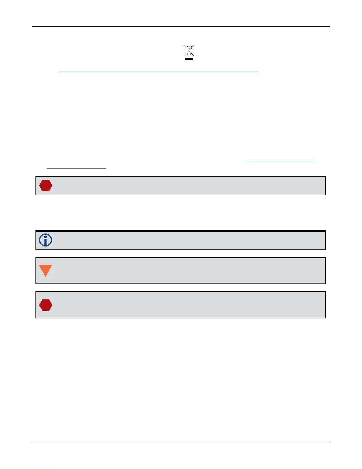
WEEE Notice
If you purchased your SMART7 product in Europe, please return it to your dealer or supplier at
the end of its life. The objectives of the European Community's environment policy are, in particular, to preserve, protect and improve the quality of the environment, protect human health
and utilise natural resources prudently and rationally. Sustainable development advocates the
reduction of wasteful consumption of natural resources and the prevention of pollution. Waste
electrical and electronic equipment (WEEE) is a regulated area. Where the generation of waste
SMART7 Installation and Operation User Manual 0A 7
SMART7 Notices
Preliminary 3
cannot be avoided, it should be reused or recovered for its material or energy. WEEE products
may be recognized by their wheeled bin label ( ).
See www.novatel.com/products/compliance/environmental-compliance for more information.
RoHS
The SMART7 is in conformity with Directive 2011/65/EU of the European Parliament and of the
council of 8 June 2011 on the restriction of the use of certain hazardous substances in electrical
and electronic equipment.
REACH
The SMART7 is compliant with Regulation (EC) No. 1907/2006 of the European Parliament and
the Council of 18 December 2006 concerning the Registration, Evaluation, Authorization and
Restriction of Chemicals (REACH). The candidate list of Substances of Very High Concern (SVHC)
published by the European Chemical Agency (ECHA) is available at: https://echa.europa.eu-
/candidate-list-table
Cables may contain DEHP (CAS Number 117-81-7) in concentrations above 0.1% w/w.
Conventions
The following conventions are used in this manual:
Information that supplements or clarifies text.
A caution that actions, operation or configuration may lead to incorrect or improper use
of the hardware.
A warning that actions, operation or configuration may result in regulatory noncompliance, safety issues or equipment damage.
SMART7 Installation and Operation User Manual 0A 8
Customer Support
Preliminary 3
Customer Support
NovAtel Knowledge Base
If you have a technical issue, visit the NovAtel Support page at www.novatel.com/support.
Through the Support page, you can contact Customer Support, find papers and tutorials or down-
load current manuals and the latest firmware.
Before Contacting Customer Support
Before you contact NovAtel Customer Support about a software problem, perform the following
steps:
If logging data over an RS-232 serial cable, ensure that the configured baud rate can support the data bandwidth (see SERIALCONFIG command). NovAtel recommends a min-
imum suggested baud rate of 115200 bps.
1.
Log the following data to a file on your computer for 15 minutes:
RXSTATUSB onchanged
RAWEPHEMB onchanged
GLORAWEPHEMB onchanged
BESTPOSB ontime 1
RANGEB ontime 1
RXCONFIGA once
VERSIONA once
For SPAN systems, add the following logs to the above list in the file created on your computer:
RAWIMUSXB onnew
INSUPDATESTATUSB onnew
INSPVAXB ontime 1
INSCONFIGA once
2.
Send the data file to NovAtel Customer Support: support@novatel.com
3.
You can also issue a FRESET command to the receiver to clear any unknown settings.
The FRESET command will erase all user settings. You should know your configuration
(by requesting the RXCONFIGA log) and be able to reconfigure the receiver before you
send the FRESET command.
If you are having a hardware problem, send a list of the troubleshooting steps taken and the results.
Contact Information
Log a support request with NovAtel Customer Support using one of the following methods:
Log a Case and Search Knowledge:
SMART7 Installation and Operation User Manual 0A 9

Customer Support
Preliminary 3
Website: www.novatel.com/support
Log a Case, Search Knowledge and View Your Case History: (login access required)
Web Portal: https://novatelsupport.force.com/community/login
E-mail:
support@novatel.com
Telephone:
U.S. and Canada:1-800-NOVATEL (1-800-668-2835)
International:+1-403-295-4900
SMART7 Installation and Operation User Manual 0A 10

Chapter 1 SMART7 Overview
Preliminary 3
The SMART7 is a high performance GNSS receiver and antenna, capable of receiving and tracking all current GNSS signals on a maximum of 555 channels. SBAS (Satellite Based Augmentation Systems) includes WAAS (North America), EGNOS (Europe) and MSAS (Japan). SBAS
support is standard. Refer to An Introduction to GNSS (on our website at www.novatel.com/an-
introduction-to-gnss) for an overview of each of the above signal types. The SMART7 features
Light Emitting Diodes (LEDs) for status indication.
Once properly powered, the SMART7 begins operating as a fully functional GNSS system.
1.1 Features and Models
The main features of the SMART7 are:
l
an enhanced high performance multi-frequency, multi-constellation receiver
l
a high performance GNSS multi-frequency, multi-constellation antenna
l
a CAN port
l
three (3) RS-232 COM ports
l
up to three (3) LED status indicators (model dependent)
l
a water and dust tight enclosure
l
enhanced interference mitigation
The SMART7 is available in several different hardware configuration and firmware models
whose additional features may include:
l
Emulated Radar Output
l
Terrain Compensation
l
Wi-Fi interface
l
Ethernet port
l
Integrated SPAN GNSS+INS functionality
l
Web UI
Contact NovAtel Sates at www.novatel.com/where-to-buy/contact-us for information regarding
available models, upgrading a model to increase feature/functionality or go to www.nova-
tel.com/support/info/documents/925 to obtain product updates. Refer toFirmware Updates and
Model Upgrades for details.
Table 1: Model Variants
Product Hardware Model Model
SMART7 SM7
SMART7 with Wi-Fi and Ethernet SM7-i
SMART7 with Wi-Fi SM7-w
SMART7 Installation and Operation User Manual 0A 11
SMART7 with SPANIMU SM7-SP
SMART7 with SPANIMU and Wi-Fi SM7-SPi

Chapter 1 SMART7 Overview
Preliminary 3
Tilt is a model variant available on all models with the exception of the SPANIMU variant.
Figure 1: SMART7 with Ethernet Model
1.2 SMART7 Connectors Overview
All SMART7 models use the same connector for power and communication. Refer to Table 14:
SMART7 Connector Pin Out on page33 for cable dimensions and pin outs.
Figure 2: SMART7 Interface Connector
The SMART7 Ethernet model has a M12 D-code female.
Figure 3: SMART7 Ethernet Connector (model dependent)
SMART7 Installation and Operation User Manual 0A 12

Chapter 1 SMART7 Overview
Preliminary 3
Table 2: Ethernet Connector Pin Outs
From P1 To J1 Signal Name
1 1 Tx+
2 2 Rx+
3 3 Tx-
4 4 Rx-
Shell Shell Chassis GND
1.3 SMART7 LEDs
The SMART7 has up to three LEDs (model dependent) to indicate receiver status.
The following tables provide information about the SMART7 LEDs and their states.
Figure 4: SMART7 LEDs Location
Table 3: SMART7 Status Indicators
Label Description
Wi-Fi (AP, Concurrent or Client)
Ethernet (DATA)
Status (Power/GNSS)
SMART7 Installation and Operation User Manual 0A 13

Chapter 1 SMART7 Overview
Preliminary 3
Green Solid Configured as AP(default)
Green Slow Flash AP and connected to a Client or Concurrent
Blue Solid Configured as Concurrent
Blue Slow Flash Concurrent and connected to an APor Client
White Solid Configured as Client
While Slow Flash Client and connected to an AP or Concurrent
Yellow Slow Flash Firmware Upgrade
Red Solid No Configuration
Red Fast Flash Error State or Dead
Table 4:
Wi-Fi LED
State Description
Table 5: Ethernet LED
State Description
Green Solid Link
Green Slow Flash Active (receiving or transmitting)
Table 6: Status LED
State Description
Green Solid RTK/PPP Solution good or RTK/PPP/INS Solution good
Green Slow Flash PPPor RTKConverging
Yellow Solid WAAS/Single Point
Yellow Slow Flash (1 Hz) Tracking
Yellow Fast Flash (3 Hz) Initialized (ME_READY)
Red Solid Power On/Error/Reset
Red Slow Flash (1 Hz) Position Error
Red Fash Flash (3 Hz) Solution Error
SMART7 Installation and Operation User Manual 0A 14

Chapter 1 SMART7 Overview
Preliminary 3
1.4 SMART7 Emulated Radar
1.4.1 Emulated Radar (ER)
A typical radar sensor emits radio beams that bounce off the ground and computes ground speed
based on the speed at which objects are passing in front of the sensor. The output of the sensor
is a digital pulse, the frequency of which is proportional to the vehicle’s ground speed. This is
often used in agricultural applications such as planting and spraying. The SMART7 eliminates the
need for separate ground-sensing radar equipment by converting the GPS-derived velocity to
proportional frequency output. The following emulated radar signal parameters can be configured by the customer:
l
Frequency Step: Specifies how the frequency output relates to the vehicle speed.
l
Signal Update Rate: Specifies how often the frequency output is updated to match the
vehicle speed.
l
Response Mode: Specifies how quickly changes in velocity are reflected in the frequency output. Setting a slower response mode reduces spikes (noise) in the velocity but increases
latency. Setting a higher response mode reduces latency, but may result in noisier frequency
output.
Refer to RADARCONFIG command for detailed information.
After it is configured using the RADARCONFIG command, Emulated Radar (ER) pulses are output
through the SMART7 interface cable and theRADARSTATUS log.
1.5 Configuring the CAN Bus
To enable an OEM7 receiver to communicate over the CAN bus, configure CAN and place the
receiver on bus, triggering a J1939 Address Claim Procedure.
1.
Use the J1939CONFIG command to specify J1939 NAME and desired address.
2.
Use the CANCONFIG command to place the receiver on bus.
3.
Optionally, use the J1939STATUS log to monitor CAN status on the receiver.
1.5.1 Configuration Notes
l
The J1939CONFIG and CANCONFIG commands can be entered in any order. After the
CANCONFIG command is used to place the receiver on the CAN bus, J1939CONFIG com-
mands take effect immediately whether entered before or after CANCONFIG. Until then,
J1939CONFIG can be entered many times to change the settings because they have not
taken affect yet (the receiver is not yet on the bus).
l
The J1939 Address claim procedure is executed if and only if both J1939CONFIG NODEx
CANx and CANCONFIG CANx ON are entered.
l
Use J1939STATUS log to determine the receiver's CAN status and the actual address claimed
by a particular node.
l
Once the receiver is "on bus", it must be taken "off-bus" using CANCONFIG for any further
configuration changes using J1939CONFIG.
l
The receiver is fully "on-bus" only once the J1939 address has been successfully claimed.
This is reported as "CLAIMED" status by J1939STATUS log.
SMART7 Installation and Operation User Manual 0A 15

Chapter 1 SMART7 Overview
Preliminary 3
l
No messages will be sent or received until the receiver is "online" and an address is claimed.
Outgoing messages are not buffered; they are discarded until the receiver is online.
1.5.2 Example of Enabling the CAN Bus
1.
LOG J1939STATUS ONCHANGED
2.
J1939CONFIG NODE1 CAN1 <addresses>
3.
CANCONFIG CAN1 ON 250K
4.
SAVECONFIG
< J1939STATUS NODE1 DISABLED 0 0xFE
< J1939STATUS NODE1 CLAIMING 1 <address>
< J1939STATUS NODE1 CLAIMED <attempt count> <address>
1.5.3 Example of Modifying the CAN Bus Parameters
1.
LOG J1939STATUS ONCHANGED
2.
CANCONFIG CAN1 OFF
3.
J1939CONFIG NODE1 CAN1 <addresses>
4.
CANCONFIG CAN1 ON
5.
SAVECONFIG
< J1939STATUS NODE1 DISABLED 0 0xFE
< J1939STATUS NODE1 CLAIMING 1 <address>
< J1939STATUS NODE1 CLAIMED <attempt count> <address>
1.5.4 Example of Detecting an Address Claim Failure and Reconfiguring
1.
LOG J1939STATUS ONCHANGED
2.
J1939CONFIG NODE1 CAN1 <addresses>
3.
CANCONFIG CAN1 ON
< J1939STATUS NODE1 DISABLED 0 0xFE
< J1939STATUS NODE1 CLAIMING 1 <address>
< J1939STATUS NODE1 FAILED <attempt count> 0xFE
4.
CANCONFIG CAN1 OFF
< J1939STATUS NODE1 DISABLED 0 0xFE
5.
J1939CONFIG NODE1 CAN1 <addresses>
6.
CANCONFIG CAN1 ON
< J1939STATUS NODE1 CLAIMING 1 <address>
< J1939STATUS NODE1 CLAIMED <attempt count> <address>
1.5.5 Address Claim Procedure
To become operational on the CAN bus, an OEM7 receiver must claim a J1939 address. The preferred address and a range of alternative addresses are specified using the J1939CONFIG
SMART7 Installation and Operation User Manual 0A 16

Chapter 1 SMART7 Overview
Preliminary 3
command. When a configured receiver is placed on bus, it may make multiple attempts to claim
an address. It may also have its address bumped by a higher priority device claiming the same
address.
While the device is attempting to claim an address, the J1939STATUS log reports a status of
CLAIMING and automatically tries to claim the next allowed address. Depending on the
J1939CONFIG parameters, an address different from the J1939CONFIG preferred address
may be claimed or the address claim procedure can fail entirely. If no addresses could be
claimed, a FAILED status is reported and the receiver takes no further action. To recover from
this failure, take the receiver off bus using the CANCONFIG command and change the CAN
address configuration using the J1939CONFIG command.
The address can also be assigned using J1939 Commanded Address message sent by another
ECU on the bus, such as a tester unit. The commanded address always overrides the address
specified using J1939CONFIG command. When the Commanded Address is received, the
receiver reports a status of CLAIMING followed by CLAIMED. Restarting CAN using the
J1939CONFIG command or CANCONFIG command clears the commanded address; the
Address Claim procedure will be executed again based on parameters specified in the
J1939CONFIG command.
SMART7 Installation and Operation User Manual 0A 17

Chapter 2 SMART7 Installation Overview
Preliminary 3
When the appropriate equipment is selected, complete the following steps to set up and begin
using the NovAtel GNSS receiver.
Figure 5: SMART7 Installation
1.
Mount the SMART7 receiver. Refer to Mounting and Orienting the SMART7 on the next page
for mounting details.
2.
Connect the receiver to other GNSS system components, such as a computer or data terminal, using the communication ports or Wi-Fi.
See Connect the SMART7 to Data Communication Equipment on page21 to Data Com-
munication Equipment.
3.
Connect other GNSS system components using the input and output lines.
See SMART7 Interface Cable on page33.
4.
Connect the supplied interface cable to the interface connector on the receiver and then connect the power cable to the power supply.
Ensure a 5 A slow blow fuse is incorporated in the power wiring. Refer to SMART7 Interface
SMART7 Installation and Operation User Manual 0A 18

Chapter 2 SMART7 Installation Overview
Preliminary 3
Cable on page33 and SMART7 Additional Equipment Required for fuse recommendations.
See Connect Power to the SMART7 on page22 and Power Supply Requirements for the
SMART7 below for details.
Refer to SMART7 LEDs on page13 for details of SMART7 LED states.
Refer to SMART7 Additional Equipment Required for fuse recommendations.
2.1 Power Supply Requirements for the SMART7
The SMART7 requires a power supply that provides:
l
a voltage in the range of +7 to +30 VDC
l
at least 15 W of power (typical use: 3 W to 7 W)
See SMART7 Environmental and Electrical Specifications on page30 for more power supply spe-
cifications.
The SMART7 has an internal power module that:
l
filters and regulates the supply voltage
l
protects against over-voltage, over-current and high-temperature conditions
l
provides automatic reset circuit protection
If the voltage supplied is below the minimum specification, the receiver suspends
operation. If the voltage supplied is above the maximum specification, the receiver
may be permanently damaged, voiding the warranty.
The supply must be capable of providing enough current to operate the SMART7,
including the initial inrush transient. The supply must also be current limited to 5 A
with an external fuse.
The amount of power required depends on the number of constellations and signals
tracked, and the features enabled.
Refer to SMART7 Interface Cable on page33 for details about the power cable.
2.2 Mounting and Orienting the SMART7
2.2.1 Mounting
Mount on a secure, stable structure capable of safe operation in the specific environment.
l
If installing on a vehicle, mount the SMART7 on the vehicle roof, ideally close to the pivot
point of the vehicle. The SMART7 must be mounted with the connector facing the rear of the
vehicle.
SMART7 Installation and Operation User Manual 0A 19

Chapter 2 SMART7 Installation Overview
Preliminary 3
Figure 6: SMART7 Magnetic Mounting Plate
The SMART7 must be rigidly secured to the vehicle to avoid errors caused by vibration
and motion.
l
If installing in a stationary location, mount the SMART7 in a location that has a clear view of
the sky so that each satellite above the horizon can be tracked without obstruction. For more
information, refer to An Introduction to GNSS.
Refer to SMART7 Mounting Plate Specifications on page35 for plate dimensions and mounting
hole locations.
2.2.2 Orienting
Ensure SMART7 the is oriented with the connector(s) facing the back of the vehicle.
Figure 7: SMART7 Orientation
SMART7 Installation and Operation User Manual 0A 20

Chapter 2 SMART7 Installation Overview
Preliminary 3
2.3 Connect the SMART7 to Data Communication Equipment
The SMART7 can communicate with other devices in the system, such as computers Wi-Fi or Ethernet ports. The SMART7 also has a CAN bus port for communication with other CAN bus compatible devices.
Wi-Fi and Ethernet are model dependent.
2.3.1 Wi-Fi
The SMART7 has a Wi-Fi Access Point that is enabled by default. This provides for easy connection to any laptop/tablet/smartphone with Wi-Fi capability and a web browser.
1.
Once the receiver is installed and powered, use a Wi-Fi capable laptop/tablet/smartphone to
locate the SMART7 in the list of detected Wi-Fi Networks and establish a connection.
The SMART7 SSID is printed on a label on the bottom of the receiver. The format of the SSID
is SMART7-<Receiver PSN>, e.g. "SMART7-ABCDEF1234567".
2.
A prompt for a password will appear. The default password is printed on a label on the bottom of the SMART7. The default password is specific to that SMART7 receiver.
3.
Open up a web browser and enter any web address (e.g., novatel.com). The SMART7 automatically redirects you to the NovAtel Web User Interface which is hosted on the SMART7.
NovAtel Web User Interface is compatible with recent versions of Chrome, Firefox, Internet Explorer and Safari.
Cookies should always be on and never blocked on the browser being used to connect to
the Wi-Fi network.
For more information about using the NovAtel Web User Interface, refer to the online OEM7 documentation (docs.novatel.com/OEM7).
To change the configuration of the Wi-Fi interface, including password, refer to Wi-Fi Configuration.
2.3.2 Ethernet Port
The SMART7 has an M12 D-code (male) socket that supports 10Base-T/100Base-TX Ethernet for
communications with external data communications equipment such as computers and data loggers. The Ethernet port supports IPv4 Internet layer, TCP/IP transport, ping and connection from
a Telnet client. Users can conduct remote debugging, accept MRTCA (modified RTCA) data and
download firmware. OEM7 receivers are also equipped with NTRIP Version 2.0 (Networked
Transport of RTCM via Internet Protocol) client and server capability.
Refer to Ethernet Configuration for instructions on configuring Ethernet and NTRIP.
SMART7 Installation and Operation User Manual 0A 21

Chapter 2 SMART7 Installation Overview
Preliminary 3
2.3.3 CAN Bus Port
The SMART7 has a CAN Bus port available on the 14-Pin interface connector.
To connect to the CANBus port:
1.
Connect the SMART7 optional accessory cable or a custom made cable, to the main 14-Pin
interface connector.
For information about the SMART7 interface cable, see SMART7 Interface Cable on page33.
This section also has the connector pin out and connector recommendations for making a custom cable.
The SMART7 interface cable, see SMART7 Interface Cable on page33, is an accessory that
provides individual wires for the CAN Bus signals.
2.
Connect the CAN leads to the CANBus.
The SMART7 CAN bus port is unterminated. If the SMART7 is at the end of the bus, then
the connecting cable must have 120 ohms integrated into the cable between CANH and
CANL in close proximity to the main 14-Pin interface connector.
2.4 Connect I/OSignals to the SMART7
The SMART7 has several inputs and outputs, also referred to as strobes, that provide status and
synchronization signals.
l
Pulse Per Second (PPS) output
l Emulated Radar Output
For more information about the I/O signals, refer to the .
To access the I/O signals, connect the SMART7 interface cable or a custom made cable, to the
main 14-Pin interface connector. Refer to SMART7 Interface Cable on page33 for connector pin
out and other details.
2.5 Connect Power to the SMART7
To connect power to the SMART7:
1.
Connect the SMART7 User Interface Cable (01019944) to the 14-Pin connector on the back of
the SMART7. See SMART7 Interface Cable on page33 for information about this cable.
2.
Connect the bare wires of the power cable to a 7 to 30 VDC power supply.
For details about the power supply required, see Power Supply Requirements for the
SMART7 on page19
2.5.1 Fuse for the Power Supply
Install a user supplied 5 A slow blow fuse in the positive line of the connection to the power
source to protect the power supply wiring and your warranty.
SMART7 Installation and Operation User Manual 0A 22

Chapter 2 SMART7 Installation Overview
Preliminary 3
Refer to SMART7 Additional Equipment Required for fuse recommendations.
2.6 Check that the SMART7 is Working
After the SMART7 is installed, powered up and use the following procedure to ensure the
receiver is operating.
1.
Check that the Status LED Fast Flashes Yellow (in the ME_READYstate).
The Status LED may briefly flash as Red before moving quickly to the Fast Flash Yellow.
See SMART7 LEDs on page13 for the location of the LEDs.
2.
Send the following command:
LOG VERSION
The VERSION log is returned.
[COM1]<VERSION COM1 0 90.5 UNKNOWN 0 19.425 0244c000 3681 14843
< 8
< GPSCARD "DDNRNNTBE" "BMHR18040058F" "OEM7700-1.01"
"OM7CR0501EN0001" "OM7BR0002RB0000" "2018/May/29" "12:03:27"
< OEM7FPGA "" "" "" "OMV070001RN0000" "" "" ""
< WIFI "RS9113" "" "" "1.7.0" "" "2018/May/29" "12:03:54"
< APPLICATION "" "" "" "ES7AR0501EN0001" "" "2018/May/29"
"12:03:39"
< DEFAULT_CONFIG "" "" "" "ES7CR0501EN0001" "" "2018/May/29"
"12:03:49"
< PACKAGE "" "" "" "ES7PR0501EN0001" "" "2018/May/29" "12:03:44"
< ENCLOSURE "" "NMPX18130002Z" "0.0.0.0" "" "" "" ""
< REGULATORY "US" "" "" ""
SMART7 Installation and Operation User Manual 0A 23

Chapter 2 SMART7 Installation Overview
Preliminary 3
3.
Check that the Time Status is FINESTEERING which represents that time is fine set and
being steered.
4.
Check the Receiver Status word (02004020 in this example). If the lowest bit (bit 0) is set,
the receiver has errors.
For information about the other digits in Receiver Status word, refer to the
RXSTATUS log in the OEM7 Commands and Logs Reference Manual.
SMART7 Installation and Operation User Manual 0A 24

APPENDIX A SMART7 Technical Specifications
Preliminary 3
Table 7: SMART7 Physical Description
Size 218 L mm x 190 W mm x 65 H mm
Weight SMART7 <1 kilograms
SMART7
NovAtel Part Number
See the following sections for more information about the SMART7:
l
SMART7 Performance Specifications on the next page
l
SMART7 Mechanical Specifications on page29
l
SMART7 Environmental and Electrical Specifications on page30
l
SMART7 Data Communication Specifications on page31
l
OEM7700 Strobe Specifications
For information about the cable available for the SMART7, see the following:
l
SMART7 Interface Cable on page33
SMART7 Installation and Operation User Manual 0A 25

A.1 SMART7 Performance Specifications
Preliminary 3
All specifications subject to GNSS system characteristics.
These specifications apply to the SMART7 and SMART7-SPAN.
Table 8: SMART7 Receiver Performance
RMS 95%
Horizontal Position
Accuracy
1
Pass to Pass
Accuracy
2
Single Point
NovAtel
CORRECT
Single Point
4
SBAS
L1 only 1.5 m
L1/L2 1.2 m
2
SBAS
0.4 m
DGPS 0.4 m
2.4 m
2.0 m
0.6 m
0.8 m
PPP
TerraStar-L
TerraStar-C
TerraStar-C
3
PRO
RTK 1 cm + 1 ppm
3
40 cm
4 cm
4 cm
50 cm
5 cm
5 cm
2.5 cm + 2 ppm
RMS 95%
4
L1 GLIDE ≤34.5 cm ≤86 cm
L1/L2 GLIDE ≤21 cm ≤35 cm
L1 GLIDE ≤19 cm ≤45 cm
L1/L2 GLIDE ≤15 cm ≤20 cm
1
Typical values. Performance specifications in open sky conditions and are subject to GPS system characteristics,
US DOD operational degradation, ionospheric and tropospheric conditions, satellite geometry, baseline length,
multipath effects and the presence of intentional or unintentional interference sources.
2
GPS only.
3
TerraStar subscriptions are available from NovAtel or TerraStar.
4
Pass-to-pass accuracy over a period of 900 seconds when using GLIDE. GLIDE is a relative positioning filter
specifically designed for use in open sky pass to pass applications. Absolute accuracy is not guaranteed.
SMART7 Installation and Operation User Manual 0A 26

APPENDIX A SMART7 Technical Specifications
Preliminary 3
TerraStar-L ≤10 cm ≤15 cm
NovAtel
CORRECT
3
L1 C/A codes 4 cm 15 cm
L1 carrier phase 0.5 mm 1.5 mm
L2 P(y) code
Measurement
Precision (RMS)
2
L2 carrier
5
phase
L2C code
2
L2C carrier
6
phase
Channel Configuration 555 Channels
GPS L1, L2, L2C
GPS (optional) L5
TerraStar-C ≤1.5 cm ≤3.0 cm
TerraStar-CPRO ≤1.5 cm ≤3.0 cm
RTK 1 cm + 1 ppm
2.5 cm + 2 ppm
GPS GLONASS
1
8 cm 8 cm
1.0 mm 1.5 mm
8 cm 8 cm
1.0 mm 1.5 mm
GLONASS L1, L2
Signals Tracked
GLONASS
(optional)
BeiDou
(optional)
Galileo
(optional)
L1 CDMA, L2 CDMA
B1, B2
E1, E5 AltBOC, E5a, E5b
NavIC(IRNSS)
SBAS L1
QZSS L1, L2
L-Band Up to 5 channels
1
L2 P for GLONASS
2
L2 C/A for GLONASS.
3
Currently the receiver can track up to 3 L-Band channels.
3
SMART7 Installation and Operation User Manual 0A 27

APPENDIX A SMART7 Technical Specifications
Preliminary 3
Minimum Satellites Tracked
1
Minimum Satellite Used in Computing
Position
7
Measurements
Maximum Data Rate
Position
Hot: <20 s typical (Almanac and recent ephemeris saved and approximate
position and time entered)
Time to First Fix
Cold: <40 s typical (No almanac or ephemeris and no approximate
position or time)
L1 0.5 s typical
Signal Reacquisition
L2 <1.0 s typical
Time Accuracy
Velocity Accuracy
2
3
20 ns RMS
<0.03 m/s RMS
The IMU performance specifications apply to the SMART7 only.
>44
>52
up to 20 Hz
up to 20 Hz
Table 9: SMART7 IMU Performance
Gyroscope Performance
Input Rate (max) ±150 °/second
Bias Repeatability 0.5 °/second
Bias Instability 3.5 °/hour
Angular Random Walk 0.1 °/√hour
Accelerometer Performance
Accelerometer Range ±5 g
Bias Repeatability 15 mg
Bias Instability 0.1 mg
Velocity Random Walk 0.05 m/s/√hour
1
These specifications refer to the processing power of the GNSS receiver. The receiver shall have the processing
power to track at least 44 satellites (if visible) and be able to use the observations from 52 satellites to compute the
position.
2
Time accuracy does not include biases due to RF or antenna delay.
3
Export licensing restricts operation to a maximum of 515 metres per second.
SMART7 Installation and Operation User Manual 0A 28

APPENDIX A SMART7 Technical Specifications
Preliminary 3
A.2 SMART7 Mechanical Specifications
l
Figure 8: SMART7 Dimensions below
l
Figure 9: SMART7-SPAN Center of Navigation below
Figure 8: SMART7 Dimensions
Dimensions are in millimetres.
SMART7 Installation and Operation User Manual 0A 29
Figure 9: SMART7-SPAN Center of Navigation

APPENDIX A SMART7 Technical Specifications
Preliminary 3
A.3 SMART7 Environmental and Electrical Specifications
Table 10: SMART7 Environmental Specifications
Operating Temperature -40°C to +70°C
Storage Temperature -45°C to +80°C
Humidity MIL-STD-810G(CH1), Method 507.6
Immersion MIL-STD-810G(CH1), Method 512.6
Ingress Protection Rating IP67
Shock MIL-STD-810G(CH1), Method 516.7
Solar Radiation EN60950-22 8.2, ISO 9022-9, Method 20, Severity Degree 03
Salt Fog IEC 60068-2-11
Sand and Dust MIL-STD-810G(CH1), Method 507.6
Random Vibration MIL-STD-810G(CH1), Method 514.7
Sinusoidal Vibration IEC 60068-2-6, Test Fc
Table 11: SMART7 Power Requirements
Voltage +7 to +30 VDC
4 W typical, value for GPS L1/L2
Power
Consumption
These are typical values using serial ports without interference mitigation. These values can change with the number of satellites in view,
firmware version, data logging rates and features in use. Use them as
a guide for what you might expect but not as absolute values
SMART7 Installation and Operation User Manual 0A 30

APPENDIX A SMART7 Technical Specifications
Preliminary 3
A.4 SMART7 Data Communication Specifications
Table 12: Data Communications Interfaces
COM1, COM2, COM3
Electrical format RS-232
Data rates
Signalssupported COM1_Tx, COM1_Rx, COM2_Tx, COM2_Rx, COM3_Tx, COM3_Rx
SMART7 port 14-Pin Tyco Ampseal
Electrical Format ISO 11898-2
Data rates
SMART7 port 14-Pin Tyco Ampseal
Physical layer 10BASE-T/100BASE-TX
SMART7 port M12 D-codemale
Security WPA2
Encryption AES
1
2400, 4800, 9600 (default), 19200, 38400, 57600, 115200, 230400 bit/s
CAN Bus
1 Mbps maximum.
CAN Bus throughput is determined by slowest device on the bus
ETHERNET
Wi-Fi Access Point
Wi-Fi Client Point
Security
Encryption
A.5 SMART7 Strobe Specifications
All of the SMART7 strobe signals are available on the 14-Pin Interface connector. Pulse Per
Second (PPS) strobes provide status and synchronization signal.
Refer to SMART7 Interface Cable on page33 for pin out details.
1
Data rates higher than 115200 bit/s are not supported by standard PC hardware. Special PC hardware may be
required for higher rates, including 230400 bit/s and 460800 bit/s.
SMART7 Installation and Operation User Manual 0A 31

APPENDIX A SMART7 Technical Specifications
Preliminary 3
Table 13: SMART7 Strobes Description
Strobes Input/Output Comment
Emulated
Radar (ER)
PPS Output
Output
0VDC to VBATT+ (also refer to SMART7 Interface Cable on the
next page)
3.3V CMOS
A time synchronization output. This is a pulse where the leading
edge is synchronized to receiver calculated GNSS Time. The
polarity, period and pulse width can be configured using the
PPSCONTROL command
SMART7 Installation and Operation User Manual 0A 32

APPENDIX A SMART7 Technical Specifications
Preliminary 3
A.6 SMART7 Interface Cable
The SMART7 interface cable is 01019944. This cable provides access to all of the signals available on the SMART7 14 pin Tyco Ampseal connector. The exposed wires (red for positive and
black for negative) can then be connected to a vehicular power circuit (or equivalent) protected
by a 5 A fast blow fuse (user supplied).
Figure 10: SMART7 Interface Cable
Dimensions are in millimeters.
Signal Name J1 J2 J3 J4 J5 E1 E2
COM1-TXD 1 2
COM1-RXD 2 3
COM2-TXD 3 2
COM2-RXD 4 3
SMART7 Installation and Operation User Manual 0A 33
Table 14: SMART7 Connector Pin Out

APPENDIX A SMART7 Technical Specifications
Preliminary 3
Signal Name J1 J2 J3 J4 J5 E1 E2
COM3-TXD 8 2
COM3-RXD 13 3
CAN1+ 6 7
CAN1- 7 2
SIGGND 5 5
SIGGND 5 5
SIGGND 5 5
SIGGND 5 3
SIGGND 5 Flying Lead
EMD RADAR OUT 10 Flying Lead
RLYO1 11 Flying Lead
PPS/RLYO2 12 Flying Lead
PWR RET (GND) 9 Flying Lead
PWR INPUT 14 Flying Lead
Table 15: 14-Pin Interface Connector
CAN SAE J1939/ ISO 11783/ ISO 11898 Compatible
PPS Output 3.3 V CMOS Logic Compatible
High= Supply Voltage Maximum
Emulated Radar Output
Also refer to OEM7700 Strobe Specifications.
Low= 1.5 V Maximum
Load= 3K Ohm Minimum
SMART7 Installation and Operation User Manual 0A 34

APPENDIX A SMART7 Technical Specifications
Preliminary 3
A.7 SMART7 Mounting Plate Specifications
The optimal screw penetration into the SMART7 mounting holes is 6 mm (±1 mm) deep. When
selecting screws for mounting the SMART7, ensure the screw penetration does not exceed this
specification. Using excessively long screws can damage the SMART7 enclosure.
Figure 11: SMART7 Mounting Plate Dimensions (Optional)
Refer to Mounting and Orienting the SMART7 on page19 for installation details.
SMART7 Installation and Operation User Manual 0A 35
 Loading...