

Page 1
52
ON
f
U
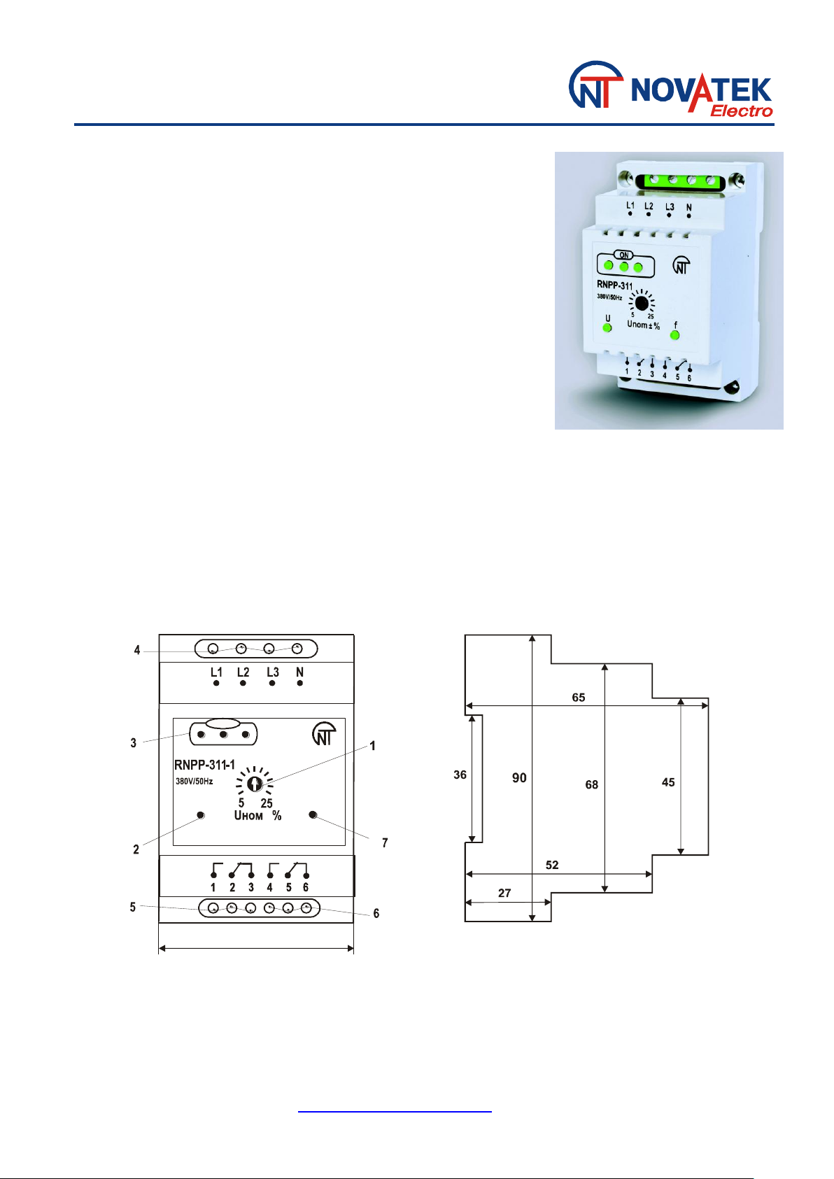
1- trip setting control for Umin/ Umax;
5- output voltage contacts;
2- green LED of the voltage output;
6- output frequency contacts;
3- green LEDs indicating voltage presence on each phase;
7- green LED of the frequency output.
4- input contacts;
RNPP-311-1
THREE PHASE NUMERICAL VOLTAGE
MONITORING RELAY WITH FREQUENCY
PROTECTION
OPERATION MANUAL
CONTROLS DESCRIPTION AND DIMENSIONS DIAGRAM
www.novatek-electro.in
Page 2

Max. Current
under ~250 V
Max. power
Max. voltage ~
Max. current under
U=30V D.C.
Cosφ = 0.4 - 1.0
2A
200VA
440V
3A
1. General Application and usage
Two channel voltage monitoring relay RNPP-311-1 is modification of standard relay RNPP-311
and performs all functions of voltage control and additional controls the network frequency. It’s
designed for tripping of load in 415 V/50Hz in case of:
Inadmissible voltage fluctuations (over voltage & under voltage), phase imbalance, phase
loss, phase coincidence (shorting of phases) and wrong phase sequence (channel U)
Inadmissible increasing / decreasing of network frequency (channel F)
2. Description
The relay is connected in parallel with load through input contacts (L1, L2, L3, N). The relay has
two independent outputs: the output for voltage (channel U) group of changeover contacts 1-2-3 and
output for frequency (channel f) group of changeover contacts 4-5-6. When the relay is not live
(voltage is not applied, the relay is not connected) the 2-3 (5-6) contacts are closed and the 1-2 (4-
5) contacts are open. When the relay is connected in parallel to load, voltage is present in the mains
and there is no cause for the relay tripping, the 2-3 (5-6) contacts open and the 1-2 (4-5) contacts
close.
Contacts potential free relay output is used to energize and de-energize the contactor’s coil. At
relay operation disconnection is carried out by opening circuit supply to coil of magnetic starter
through break contacts 1-2 (4-5).
The 1-2-3, 4-5-6 output contacts specification
Indication
-three green LEDs indicating that mains voltage exists. They signalize about the voltages
presence on all three phases. When any one or two phases are lost the corresponding LEDs go out;
-green LED of the output for the U channel. It glows when the 1-2 contacts are closed;
-green LED of the output for the 2nd channel of frequency. It glows when the 4-5 contacts are
closed.
Operation
When a voltage is applied to the relay the LEDs "Power" glow. If the voltage is normal, i. e. doesn't
fall outside the user set trip thresholds and frequency, the output contact of channel F change its
position - the 4-5 contacts close after 0.5 seconds.
Voltage output of channel U will be turn on after 5-6 seconds – 1-2 contacts close.
After that the relay provides a constant monitoring of the voltage value and frequency of network.
When there is complete absence of voltage and/or voltages fall outside the contacts 1-2 open.
The "Power" LEDs is OFF” Voltage Output”. When voltage parameters return to normal the load
starting will occur automatically when 5-6 seconds delay has expired;
When there are voltage faults output frequency doesn't trip.
When there are frequency faults contacts 4-5 close, the power LEDs is OFF “Output by F “ If there
is no voltage faults in this moment the voltage output doesn’t trip (contacts 1-2 close).
Frequency Output is blocked and contacts 4-5 open. To unblock the relay switch-off power supply
to relay and then switch-on (reset).
Page 3

Output f
Output U
Adjustment. The relay has a combined adjustable set point response by the
maximum / minimum voltage in % of rated voltage. For example, in the
position of 10% the relay will be triggered when rise and fall of voltage
happens in terms of 10% of rated voltage (240/415V).
WARNING! Recommend setting of parameters before connection to the contactor.
3. Technical brief
Rated phase / line voltage, V 240/415
Range: Umax / Umin tripping, % of rated Voltage 5 - 25
Fixed delay in Umin, seconds 12
Tripping threshold in case of phase imbalance, V 60
Fixed response time of Umax, seconds 1.5
Fixed reaction time on loss of one phase (single phasing), seconds 1.5
Auto Reset time after recovery of voltage parameters, seconds 5
The accuracy of determining of voltage threshold, V 3
Fixed setting of minimum frequency tripping, Hz 47
Fixed setting of maximum frequency tripping, Hz 57
Fixed response time of minimum frequency faults, seconds 12
Fixed response time of maximum frequency faults, seconds 1
The accuracy of determining frequency threshold, Hz ± 0.3
Operating voltage, V - 80 to 500
Short term permissible max voltage which device can withstand, V 700
Hysteresis voltage, V 6-7
The total current consumption, mA < 35
Climatic performance UHL 4
Switching resource under load of 5A, times > 100000
Operating temperature range, deg C from - 35 to +55
Storage Temperature, deg C from - 45 to +70
4. Transport and Storage
The relays in manufacturer package should be stored in enclosed rooms at – 45 to +70 °C and
exposed to no more than 90% of relative humidity when there are no fumes in the air that exert a
deleterious effect on package and the relay material. The Buyer must provide the protection of the
relay against mechanical damages in transit.
The relay is connected in parallel with according to the diagram below
WIRING DIAGRAM
Page 4

5. WARRANTY
The manufacturer guarantees trouble free operation RNPP-311-1 for 36 months (3 years) after the
date of sale, provided:
- The device is properly connected;
- The integrity of the seal of manufacturer's quality control department;
- The integrity of the hull, the absence of tampering, cracks, chips, etc.
6. CERTIFICATE OF ACCEPTANCE
Voltage relays RNPP-311-1 № ________ made and accepted in accordance with TU U 31.2310446637-001-2002 and effective technical documentation and found fit for service.
MP Head of QC Issue date
______________ ___________
Sale Date ___________
Contact:
NOVATEK ELECTRO (INDIA) PVT. LTD.
C-30, Patparganj Industrial Area, 1st floor,
Delhi – 110092, India
Tel/fax: +91 11 42143253, 43010600
Email: info@novatek-electro.in
Web: http://www.novatek-electro.in
 Loading...