

Page 1
NOVATEK-ELECTRO Ltd
Intelligent industrial electronics
TIME DELAY RELAY
REV-114
OPERATING MANUAL
The quality management system of development and production production complies with the requirements
of ISO 9001:2015
Dear Customer,
Company thanks you for purchasing our products.
You will be able to use properly the product after carefully studying the Operating Manual.
Keep the Manual throughout the service life of the product.
www.novatek-electro.in
Page 2

- 2 -
REV-114 NOVATEK-ELECTRO
WARNING! – PRODUCT TERMINALS AND INTERNAL COMPONENTS ARE UNDER POTENTIALLY
LETHAL VOLTAGE.
TO ENSURE THE PRODUCT SAFE OPERATION IT IS STRICTLY FORBIDDEN THE FOLLOWING:
– TO CARRY OUT MOUNTING WORKS AND MAINTENANCE WITHOUT DISCONNECTING THE PRODUCT
FROM THE MAINS;
– TO OPEN AND REPAIR THE PRODUCT INDEPENDENTLY;
– TO OPERATE THE PRODUCT WITH MECHANICAL DAMAGES OF THE CASE.
IT IS NOT ALLOWED WATER PENETRATION ON TERMINALS AND INTERNAL ELEMENTS OF THE
PRODUCT.
During operation and maintenance the regulatory document requirements must be met, namely:
Regulations for Operation of Consumer Electrical Installations;
Safety Rules for Operation of Consumer Electrical Installations;
Occupational Safety in Operation of Electrical Installations;
Installation, adjustment and maintenance of the product must be performed by qualified personnel having
studied this Operation Manual.
The product is safe for use under keeping of the operating rules.
Page 3
- 3 -
NOVATEK-ELECTRO REV-114
This Operation Manual is intended to familiarize you with arrangement, the requirements for safety, operation and
maintenance procedures of the time delay relay REV–114 (hereinafter referred to as the "product", "REV–114").
The product meets the requirements of the following:
IEC 60947-1 (Low-voltage switchgear; Part 1. General rules);
ІEC 60947-6-2 (Low-voltage circuit breaker and controller; Part 6-2; multifunctional equipment; Control and safety
switching equipment);
CISPR 11 (Electromagnetic compatibility; Industrial, scientific and medical RF equipment; electromagnetic interference
characteristics; standards and measuring procedure);
IEC 61000-4-2 (Electromagnetic compatibility; Part 4-2; Testing and measurement techniques; Electrostatic discharge
immunity test).
Harmful substances in amounts exceeding maximum permissible concentrations are not available.
Terms and abbreviations:
• It periodically flashes – the indicator short-time enabling.
• It periodically is off – the indicator short-time disabling.
1. APPLICATION
1.1. Product application
The time delay relay REV-114 is the microprocessor-based device intended to control the load with independent time
delay. It provides the certain sequence of the load operation according to the mode specified by the user.
REV-114 is equipped with control buttons and a digital display designed for adjustment and visual check of
timing.
REV-114 can be operated by seventeen operation algorithms:
- on-delay;
- time delay when energizing;
- periodic with on-delay;
- periodic with time delay when energizing;
- pulse generator;
- on-delay with external start;
- off delay with external start;
- pulse I with external start;
- pulse II with external start;
- on/off delay with external start;
- pitch of the load relay (during each control contact closing);
- periodic with external start and on-delay;
- periodic with external start and time delay when energizing;
- pulse generator with external start;
- start stop;
- always ON;
- always OFF.
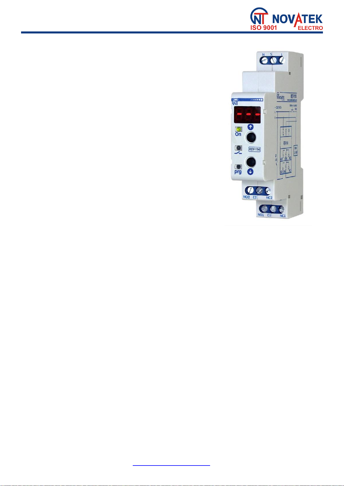
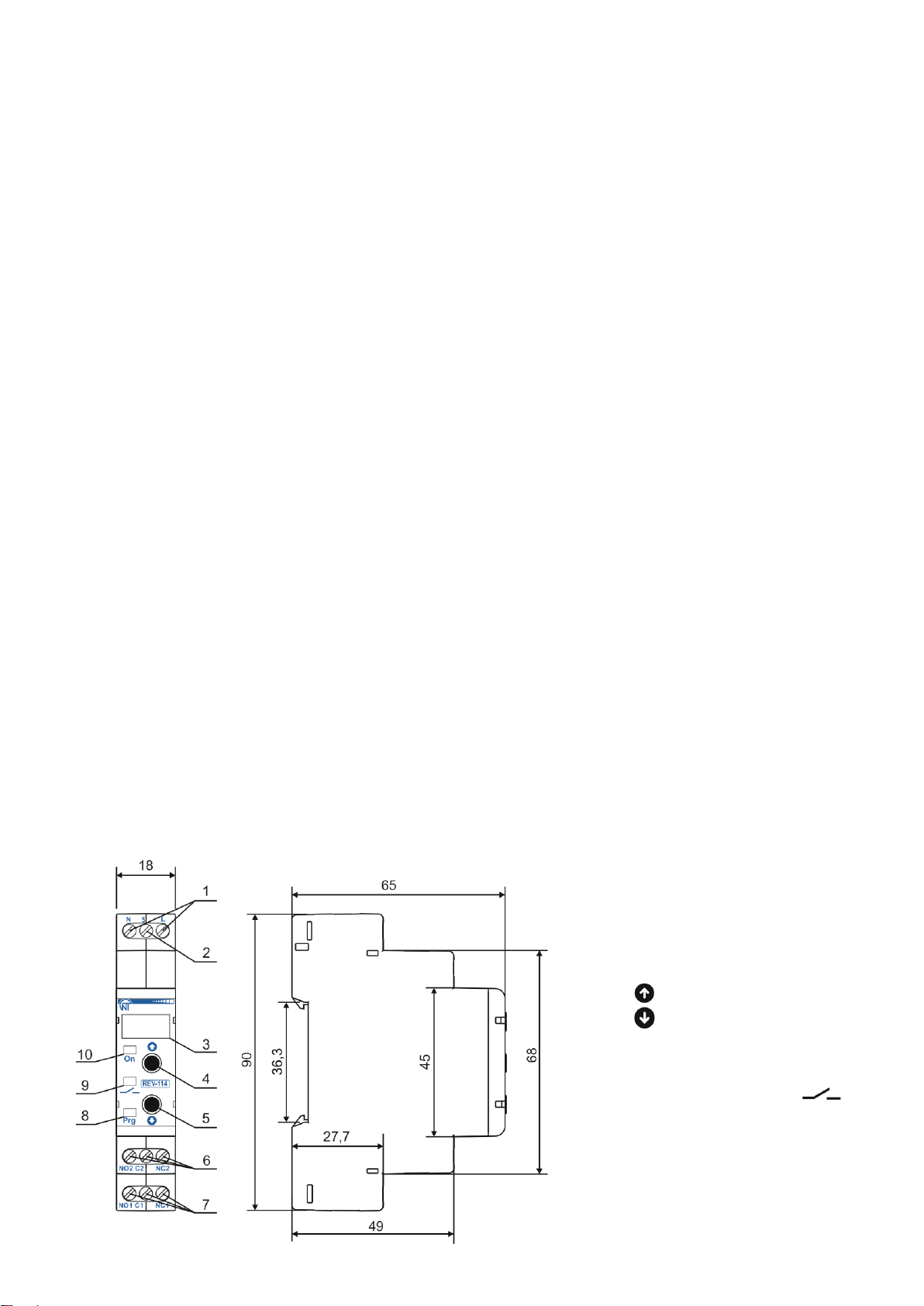
1.2. Controls, overall and mounting dimensions of REV–114
Controls, overall and mounting dimensions are shown in Fig.1.
1 – input contacts ~230/240 V N, L;
2 – input control contact S;
3 – digital indicator display;
4 – button (UP);
5 – button (DOWN);
6, 7 – output contacts of load relay
(NO, C, NC);
8 – LED indicator of setup mode prg;
9 – LED indicator of load relay ON ;
10 – LED indicator of power ON On.
Page 4

- 4 -
REV-114 NOVATEK-ELECTRO
Fig.1 – Controls, overall and mounting dimensions of REV–114
1.3. Operation conditions
The product is designed for operation in the following conditions:
– Ambient temperature: from minus 30 to +55°C;
– Atmospheric pressure: from 84 to 106.7 kPa;
– Relative air humidity (at temperature of +25°C): 30 … 80 %.
ATTENTION! The product is not intended for operation in the following conditions:
– Significant vibration and shocks;
– High humidity;
– Aggressive environment with content in the air of acids, alkalis, etc., as well as severe contaminations
(grease, oil, dust, etc.).
2. SPECIFICATIONS
2.1. Basic Specifications
Basic specifications of REV–114 are given in Table 1.
Specifications of the load relay contacts are given in Table 2.
Table 1 – Basic Specifications
Description
Value
Operating supply voltage, V:
230 / 240
Frequency of supply mains, Hz
45 – 62
Voltage at which service capability is maintained, V
185 – 280
Permissible harmonic configuration (unsinusoidality) of power supply voltage
EN 50160
Readiness time when energizing, s, no more than
0.4
Accuracy of time setting holding, %, no less than
0.5
Number of operation algorithms
17
Adjustment range of time
from 0.1 s to 10 days
Timing adjustment
Buttons on the front panel
Digit display of remaining time
available
Service of the product
Switchgear and control gear
Rated operating condition
Continuous
Type and quantity of contacts (switching)
2
Climatic design version
NC 3.1
Protection rating of case
ІР40
Protection rating of terminal box
ІР20
Commutation lifetime of output contacts if cos=1:
- under load of 6 А, time, no less than
- under load of 1 А, time, no less than
100 000
1 000 000
Power consumption (under load), W, no more than
0.5
Permissible contamination level
II
Overvoltage category
II
Electric shock protection class
II
Rated insulation voltage, V
450
Rated impulse withstand voltage, kV
2.5
Wire cross-section for connection to terminals, mm²
0.5 – 2
Tightening torque of terminal screws, N*m
0.4
Weight, kg, not more
0.150
Overall dimensions, H x D x L, mm
90 x 18 x 65
Product installation (mounting) is on standard 35mm DIN rail
The product remains functional at any position in space
Case material is self-extinguishing plastic
Table 2 – Specifications of output contacts of the load relay
сos
Max. current at
U~250 V, А
Max. switching
power, VA
Max. permissible
continuous AC voltage, V
Max. current at
UDC=28 V, A
1 6 1500
250
3
2.2. Product operation modes
The product operation modes are given in Table 3.
Page 5

- 5 -
NOVATEK-ELECTRO REV-114
Table 3 – Product operation mode
Mode number and
name
Description
1
On-delay
After energizing, the indicator ON (Fig.1 it.10)
is on and the set delay time occurs .
During the delay time the indicator
(Fig.1 it.9) periodically flashes.
At the end of the delay time the load relay
contacts C and NO are closed, the indicator
is on and the product goes into standby
mode until power-off.
2
Time delay when
energizing
After energizing, the indicator ON (Fig.1 it.10)
is on, contacts of the load relay C and NO are
closed, the indicator
(Fig.1 it.9) is on and the set delay time occurs
. During the delay time the indicator
periodically is off.
At the end of the delay time the load relay
contacts are open, the indicator is off
and the product goes into standby mode until
power-off.
3
Periodic with on-
delay
After energizing, the indicator ON (Fig.1 it.10)
is on and the set delay time occurs .
During the delay time the indicator
(Fig.1 it.9) periodically flashes.
At the end of the delay time the load relay
contacts C and NO are closed for set time
and the indicator is on. During
the delay time the indicator periodically
is off.
At the end of the delay time the load relay
contacts are open, and the product starts fulfillment of algorithm from the beginning.
4
Periodic with time
delay when
energizing
After energizing, the indicator ON (Fig.1 it.10) is
on, contacts of the load relay C and NO are
closed, the indicator
(Fig.1 it.9) is on and the set delay time occurs
. During the delay time the indicator
(Fig.1 it.9) periodically is off.
At the end of the delay time the load relay
contacts are open for set time and the
indicator is off. During the delay time the
indicator periodically flashes.
At the end of the delay time the product starts fulfillment of algorithm from the beginning.
5
Pulse generator
After energizing, the indicator ON (Fig.1 it.10)
is on and the set delay time occurs .
During the delay time the indicator
(Fig.1 it.9) periodically flashes.
At the end of the delay time the load relay
contacts C and NO are closed, and the set
delay time occurs .
During the delay time the indicator
(Fig.1 it.9) periodically is off.
At the end of the delay time the load relay
contacts C and NO are open, the indicator is off and the product goes into standby
mode until power-off.
Page 6

- 6 -
REV-114 NOVATEK-ELECTRO
Table 3 (Continued)
Mode number and
name
Description
6
On-delay with
external start
After energizing, the indicator ON (Fig.1 it.10)
is on and the product goes into standby mode,
in this case the load relay contacts C and NO
are open, and the indicator (Fig.1 it.9) is
off.
When control signal S occurs, there is the set
time delay . During the delay time the
indicator (Fig.1 it.9) periodically flashes.
At the end of the delay time the load relay
contacts C and NO are closed, the indicator
is on and the product goes into standby
mode.
When there is no the control signal S, the load relay contacts C and NO are open, the indicator
is off and the product goes into standby mode
7
Off delay with
external start
After energizing, the indicator ON (Fig.1 it.10) is
on and the product goes into standby mode, in
this case the load relay contacts C and NO are
open, and the indicator (Fig.1 it.9) is off.
When control signal S occurs, the load relay
contacts C and NO are closed, the indicator
is on and the product goes into standby
mode.
When there is no the control signal S, there is
the set time delay . During the delay time
the indicator periodically is off. At the end of the delay time the load relay contacts C
and NO are open, the indicator is off and the product goes into standby mode.
In case of repeated occurrence of the control signal S, the algorithm fulfillment is repeated.
8
Pulse I with external
start
After energizing, the indicator ON (Fig.1 it.10) is
on and the product goes into standby mode, in
this case the load relay contacts C and NO are
open, and the indicator (Fig.1 it.9) is off.
When control signal S occurs, the load relay
contacts C and NO are closed, the indicator
is on and there is the set time delay .
During the delay time the indicator
periodically is off.
At the end of the delay time the load relay
contacts are open, the indicator is off and
the product goes into standby mode..In case of absence and repeated occurrence of the
control signal S, the algorithm fulfillment is repeated.
9
Pulse II with external
start
After energizing, the indicator ON (Fig.1it.10) is
on and the product goes into standby mode, in
this case the load relay contacts C and NO are
open, and the indicator (Fig.1 it.9) is off.
When control signal S occurs, the product
remains in standby mode. When there is no the
control signal S, the load relay contacts C and
NO are closed, the indicator is on and
there is the set time delay . During the delay
time the indicator periodically is off. At the
end of the delay time the load relay contacts are
open, the indicator is off and the product goes into standby mode.
When control signal S occurs, the algorithm fulfillment is repeated.
Page 7

- 7 -
NOVATEK-ELECTRO REV-114
Table 3 (Continued)
Mode number and
name
Description
10
On/off delay with
external start
After energizing, the indicator ON (Fig.1it.10) is on
and the product goes into standby mode, in this
case the load relay contacts C and NO are open,
and the indicator (Fig.1 it.9) is off. When
control signal S occurs, there is the set time delay
. During the delay time the indicator
periodically flashes.
At the end of the delay time the load relay
contacts are closed, the indicator is on and
the pro-duct goes into standby mode. When there
is no the control signal S, there is the set time
delay . During the delay time the indicator periodically is off.
At the end of the delay time the load relay contacts are open, the indicator is off and the
product goes into standby mode.
In case of repeated occurrence of the control signal S, the algorithm fulfillment is repeated.
11
Pitch of the load
relay
After energizing, the indicator ON (Fig.1 it.10) is on
and the product goes into standby mode, in this
case the load relay contacts C and NO are open,
and the indicator (Fig.1 it.9) is off.
When control signal S occurs, the load relay
contacts and the indicator change its state to
the opposite, then the product goes into standby
mode.
When there is no the control signal S, the product
continues to be in standby mode.
In case of repeated occurrence of the control signal S, the algorithm fulfillment is repeated.
12
Periodic with external
start and on-delay
After energizing, the indicator ON (Fig.1 it.10) is
on and the product goes into standby mode, in
this case the load relay contacts C and NO are
open, and the indicator (Fig.1 it.9) is off.
When control signal S occurs, there is the set time
delay . During the delay time the indicator
(Fig.1 it.9) periodically flashes.
At the end of the delay time the load relay
contacts C and NO are closed for set time
and the indicator is on. During the delay
time the indicator periodically is off.
At the end of the delay time the load relay contacts are open, and the product starts the
algorithm fulfillment from the beginning.
When there is no the control signal S, the algorithm fulfillment is stopped, the load relay
contacts C and NO are open and the product goes into the standby mode.
13
Periodic with external
start and time delay
when energizing
After energizing, the indicator ON (Fig.1 it. 10) is
on and the product goes into the standby mode,
in this case the load relay contacts C and NO are
open, and the indicator (Fig.1 it.9) is off.
When control signal S, the load relay contacts C
and NO are closed for set time . During the
delay time the indicator (Fig.1 it.9)
periodically is off. At the end of the delay time the
load relay contacts C and NO are open for set
time and the indi-cator is off. During
the delay time the indica-tor periodically flashes.
At the end of the delay time the product starts the algorithm fulfillment from the beginning.
When there is no the control signal S, the algorithm fulfillment is stopped, the load relay
contacts C and NO are open and the product goes into the standby mode.
Page 8

- 8 -
REV-114 NOVATEK-ELECTRO
Table 3 (Continued)
Mode number and
name
Description
14
Pulse generator with
external start
After energizing, the indicator ON (Fig.1 it.10) is
on and the product goes into the standby mode,
in this case the load relay contacts C and NO
are open, and the indicator (Fig.1 it.9) is
off. When control signal S occurs, there is the set
time delay . During the delay time the
indicator (Fig.1 it.9) periodically flashes. At
the end of the delay time the load relay contacts
C and NO are closed for the set time and
the indicator is on. During the delay time
the indicator periodically is off. At the end of the delay time the load relay contacts are
open, and the product goes into the standby mode.
15
Start-stop
After energizing, the indicator ON (Fig.1 it.10) is
on and the product goes into the standby mode,
in this case the load relay contacts C and NO are
open,and the indicator (Fig.1 it.9) is off.
When control signal S occurs, there is the set time
delay . During the delay time the indicator
(Fig.1 it.9) periodically flashes. At the end of
the delay time the load relay contacts C and NO
are closed, the indi-cator is on. In case of
repeated occurrence of the control signal S, there
is the set time delay .
During the delay time the indicator (Fig.1 it.9) periodically is off.
At the end of the delay time the load relay contacts C and NO are open, the indicator is
off and the product goes into the standby mode.
16
Always ON
After energizing, the indicator ON (Fig.1 it.10) is on, the load relay contacts C and NO are
closed, the indicator is on and the product goes into the standby mode until power-off.
17
Always OFF
After energizing, the indicator ON (Fig.1 it.10) is on, the load relay contacts C and NO remain
open, and the indicator is off. The product goes into the standby mode until power-off.
3. INTENDED USE
3.1. Preparation for operation
• Unpack the product (we recommend to keep the original packing for the entire warranty period of the product
operation);
• Check the product for damage after transportation; in case of such damages detection, contact the supplier or
manufacturer;
• Carefully study the Operation Manual (pay special attention to the connection diagram to power the
product);
• If the temperature of the product after transportation or storage differs from the temperature of the environment
at which it is supposed to be operated, then before connecting to the mains hold the product under operating
conditions within two hours (because there is possible moisture condensation on the elements of the product);
• If you have any questions regarding the installation of the product, please contact the manufacturer by
telephone number indicated at the end of this Operation Manual.
3.2. Product connection
Connect the product in accordance with the diagram given in Fig.2.
ATTENTION!
THE PRODUCT IS NOT DESIGNED FOR LOAD COMMUTATION IN CASE OF SHORT CIRCUITS.
THEREFORE, THE LOAD POWER SUPPLY CIRCUIT SHOULD BE EQUIPPED WITH THE CIRCUIT BREAKER
FOR CURRENT OF 6 A MAXIMUM.
ALL CONNECTIONS MUST BE PERFORMED WHEN THE PRODUCT IS DE-ENERGIZED.
To improve performance of the product it is recommended to install the fuse or the analogue in the
power supply circuit of REV-114 for 1 A current.
To ensure the reliability of electrical connections you should use flexible (stranded) wires with insulation for
voltage of no less than 450 V, the ends of which it is necessary to be striped of insulation for 5±0.5 mm and
tightened with bootlaces. Recommended cable cross section is no less than 1.0 mm2. Wires fastening should
exclude mechanical damage, twisting and abrasion of the wire insulation.
Page 9

- 9 -
NOVATEK-ELECTRO REV-114
QF1 – Circuit breaker (fuse), maximum current is 6 А;
Fig.2 – Product connection diagram
IT IS NOT ALLOWED TO LEAVE EXPOSED PORTIONS OF WIRE PROTRUDING BEYOND THE TERMINAL
BLOCK.
For reliable contact it is necessary to perform tightening of screws of the terminal block with the force specified in
Table 1.
When reducing the tightening torque, the junction point is heated, the terminal block may be melted and wire can
burn. If you increase the tightening torque, it is possible to have thread failure of the terminal block screws or the
compression of the connected wire.
Error when performing the installation works may damage the product and connected devices.
3.3. Adjustment of the product
Energize the product.
On the front panel of the product, press and hold simultaneously the buttons and , after 3 s the indicator prg
(Fig.1 it.8) is on and the display shows the first parameter of main menu ( ), release the buttons.
Figure 3 shows the diagram for the configuration of the product.
Figure 3 – Diagram for the configuration of the product
Page 10

- 10 -
REV-114 NOVATEK-ELECTRO
The configuration of the product is performed in the following order:
• Adjustment of operation mode ( );
• Adjustment of timing ( and ).
To exit the main menu, press and hold for more than 3 seconds the buttons + . In this case the indicator
prg will off and the display shows the remaining time before switching on (off) the load relay.
If within 30 s neither button is pressed, the product will automatically exit from programming mode.
3.3.1. Adjustment of the product operation mode
Using the buttons or select the main menu item (the product operation mode), confirm the selection
by one time pressing of the buttons + . In this case the display will flash the current operation mode in the
form of a decimal number.
Using the buttons or select the required operation mode (list of the operation modes for REV-114 is given
in Table 3).
Press the buttons + one time to save the selected mode and return to the main menu.
Figure 3 shows the complete programming diagram for the product.
3.3.2. Adjustment of timing
Using the buttons or select the main menu item (on-time of the load relay), confirm the selection by
one time pressing of the buttons + . In this case, the display shows the submenu to select one of the units of
time:
▪ – days (from 0 to 10);
▪ – hours (from 0 to 23);
▪ – minutes (from 0 to 59);
▪ – seconds (from 0 to 59);
▪ – hundreds of milliseconds (from 0 to 9).
Using the buttons or select the required unit of time, confirm the selection by one time pressing of the
buttons
+ . In this case the display will flash the current value of the selected time unit.
Using the buttons or set the required value.
Press the buttons + one time to save the set value and return to the previous menu.
After setting all of the time units, press and hold the buttons + more than 3 seconds to exit to the main menu.
Total on-time of the load relay consists of the sum of the values of each time unit:
= + + + + .
Adjustment of the main menu item (off-time of the load relay) is similar.
3.4. Use of the product
After the power supply the indicator ON (Fig.1 it.10) is on and the product begins to operate according to the
User-selected mode (see Table 3), displaying the remaining time to turn on (off) the load relay.
Example of displaying the time:
▪ – 10 days;
▪ – 23 hours;
▪ – 59 minutes;
▪ – 59 seconds;
▪ – 900 milliseconds;
▪ – time account is completed.
The time is displayed by the maximum value of time unit (not equal to zero) in the order presented above.
The enabled load relay status corresponds to the closed condition of the contacts NO1-C1 (NO2-C2) and the
open condition of the contacts NC1-C1 (NC2-C2).
The disabled load relay status corresponds to the open condition of the contacts NO1-C1 (NO2-C2) and the
closed condition of the contacts NC1-C1 (NC2-C2).
Periodic flashing of light indicates the time delay after which the load relay will on.
Periodic disabling of light indicates the time delay after which the load relay will off.
Note – when energizing the product there is a small pause (no more than 300 ms) before the product starts to
operate according to the set operation mode.
4. MAINTENANCE
4.1. Safety precautions
THE TERMINALS AND THE PRODUCT INTERNAL ELEMENTS CONTAINS POTENTIALLY LETHAL
VOLTAGE.
Page 11

- 11 -
NOVATEK-ELECTRO REV-114
DURING MAINTENANCE IT IS NECESSARY TO DISABLE THE PRODUCT AND CONNECTED DEVICES
FROM THE MAINS.
4.2. Maintenance of the product must be performed by qualified service personnel.
4.3. Recommended frequency of maintenance is every six months.
4.4. Maintenance procedure:
1) Check the connection reliability of the wires, if necessary, clamp with the force specified in Table 1;
2) Visually check the integrity of the housing, in case of detection of cracks and damages to remove the product
from service and send for repair;
3) If necessary, wipe with cloth the front panel and the product housing.
Do not use abrasives and solvents for cleaning.
5. SERVICE LIFE AND MANUFACTURER WARRANTY
5.1. The lifetime of the product is 10 years. Upon expiration of the service life, contact the manufacturer.
5.2. Shelf life is 3 years.
5.3. Warranty period of the product operation is 5 years from the date of sale.
During the warranty period of operation (in the case of failure of the product) the manufacturer is responsible for
free repair of the product.
ATTENTION! IF THE PRODUCT HAS BEEN OPERATED IN VIOLATION OF THE REQUIREMENTS OF THIS
MANUAL, THE MANUFACTURER HAS THE RIGHT TO REFUSE IN WARRANTY SERVICE.
5.4. Warranty service is performed at the place of purchase or by the manufacturer of the product.
5.5. Post-warranty service of the product is performed by the manufacturer at current rates.
5.6. Before sending for repair, the product should be packed in the original or other packing excluding
mechanical damage.
You are kindly requested, in case of return of the product and transfer it to the warranty (post-warranty) service,
in the field of the claims data, list the detailed reason for return.
6. TRANSPORTATION AND STORAGE
The product in the original package is permitted to be transported and stored at the temperature from minus 45
to +60 °C and relative humidity of no more than 80 %.
7. ACCEPTANCE CERTIFICATE
REV–114 has been manufactured and accepted in accordance with the requirements of current technical
documentation and classified as fit for operation.
Seal Head of QCD Date of manufacture
_____________ _____________
8. CLAIMS DATA
______________________________________________________________________________________________
________________________________________________________________________________________________
________________________________________________________________________________________________
________________________________________________________________________________________________
________________________________________________________________________________________________
________________________________________________________________________________________________
The Company is grateful to you for the information about the quality of the product and suggestions for its operation.
For all questions, please contact the manufacturer:
NOVATEK ELECTRO INDIA PVT. LTD.
C-30, Patparganj Industrial Area, F.I.E.
Delhi – 110092, INDIA;
Tel.: +91 11 42143253
Tel./fax: +91 11 43010600
www.novatek-electro.in
Date of sale __________
Page 12

- 12 -
REV-114 NOVATEK-ELECTRO
 Loading...