

Page 1
NOVATEK-ELECTRO LTD
Research-and-Manufacture Company
RNPP-302
MULTIFUNCTIONAL
THREE PHASE VOLTAGE MONITORING RELAY
USERS MANUAL
www.novatek-electro.com
Page 2

- 2 -
APPLICATION
Universal Three phase voltage monitoring relay RNPP-302 (hereinafter RNPP-302) is designed for the
permanent voltage monitoring, control and protection of the equipment with rated voltage parameters of
220/380V and 230/400V or 240/415V at rated frequency of 50Hz. RNPP-302 protects the power load from the
following alarm situations and power faults:
- over/under voltage, voltage surges and fluctuations,
- phase loss,
- phase coincidence,
- wrong phase sequence,
- phase imbalance in the AC power circuits
- control over the full phase switching of the contactor
- remote control input signal to operate with the power load as per requirement
The RNPP-302 operates with the magnetic coil of the external contactor which in it’s turn operates with the
power load. The RNPP-302 constantly checks (before and after turning on) the condition of the power contacts
of magnetic contactor and detects the stuck together and burned contacts. When the power parameters return
back to normal after the interruption or when the reason of the tripping is eliminated the RNPP-302 performs
automatic reclosing and thus restart the equipment. It does so following a time delay (0-600 sec), set
previously by the user.
RNPP-302 relay may work in four independent modes:
1. phase loss monitoring mode without voltage level control (parameter τΠρ = 0);
2. minimum voltage monitoring mode (parameter τΠρ = 1);
3. maximum voltage monitoring mode (parameter τΠρ = 2);
4. symmetrical min/max voltage monitoring mode (parameter τΠρ = 3)
The LED display of the RNPP-302 indicates:
- Acting value (true RMS) of the phase voltage or alternatively line voltage depending on mode of
operation;
- Voltage fault in mains power supply and the type of the interruption;
- State of output relay contacts (OPEN/CLOSE)
NOTICE. The term “rated voltage” used in this device manual means that the input voltage
corresponds all settings and parameters adjusted by user (see Table 2).
Time countdown of the autoreclosing delay starts from the moment of the fault detection (not from the
moment when the power parameters recovered to their corresponding rated values)
During the countdown of the autoreclosing time delay LED indicator REL will blink in case of t he normal
power parameters.
1. MAIN FEATURES
Digital input to turn ON/OFF the RNPP-302 remotely ;
Changeover relay output (8A 250V at cos φ=1) for the operation by the magnetic contactor to commutate
any desired power load;
Normally Opened relay contact (8A 250V at cos φ=1) for the signalization
Measurement accuracy for tripping thresholds: not exceed 3V
Rated phase/line voltage 220/380V (230/400V or 240/415V)
The adjustable ranges for minimal voltage; maximal voltage tripping; phase imbalance; t ime delays for the
protection tripping; automatic restart (autoreclosing) time and other adjustable param eters are shown in the
Table 2.
Rated power consumption: not exceed 5 W
Protection degree of the enclosure case: IP40
Protection degree of terminal block: IP20
Operational temperature range, °C: from - 35 to +55
Storage temperature conditions, °C: from - 45 to +75
RNPP-302
NOVATEK-ELECTRO
Page 3
- 3 -
Weight not more than 0,3 kg
Mounting: fit the standard 35 mm DIN-rail
Mounting position: arbitrary - as per requirement
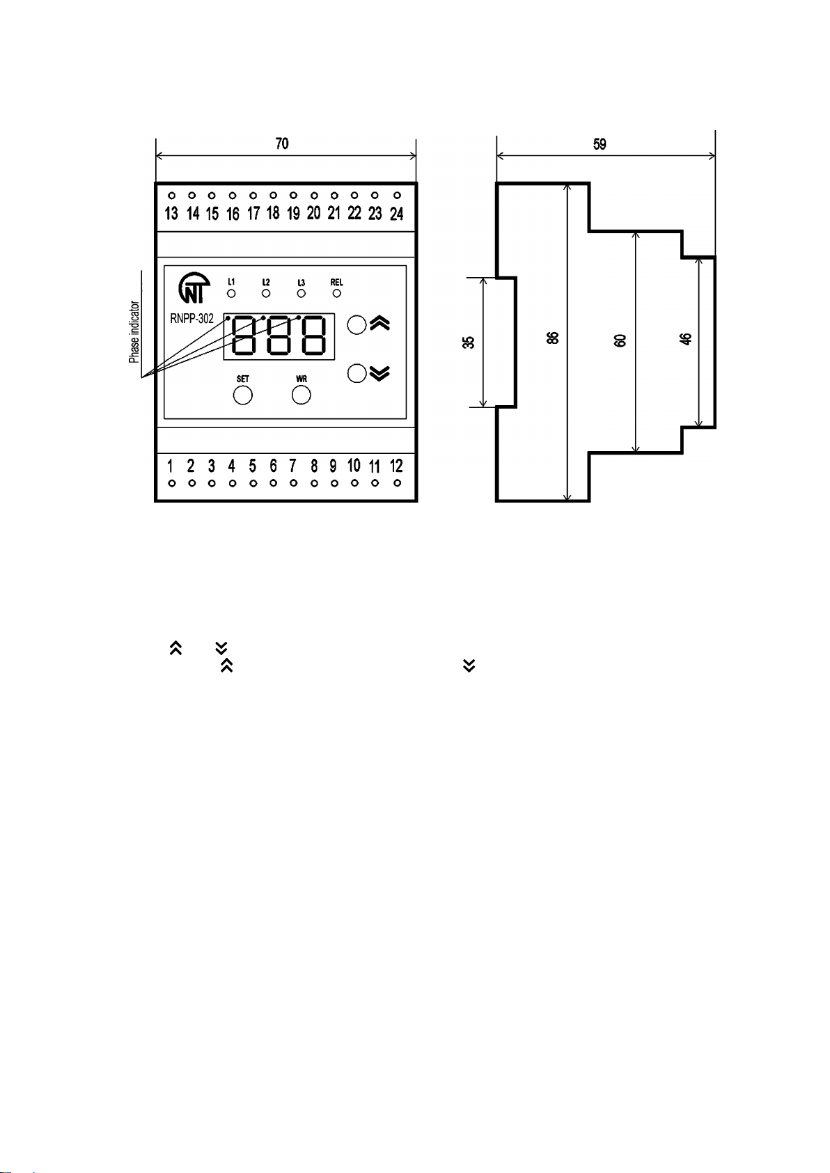
Dimensions and control buttons are shown on Figure 1.
Figure 1. Front panel, controls and size dimensions of the RNPP-302
Red LED “L1” – lights up in case of the alarm on phase L1
Red LED “L2” – lights up in case of the alarm on phase L2
Red LED “L3” – lights up in case of the alarm on phase L3
Green LED “REL” – lights up when the output relay is closed
“SET” button – to set the parameter value
“WR” – to write and save the parameter
“
and ” Buttons - to scroll and adjust the parameters value in menues
Notes:
button hereinafter in text – “UP”, button – “DOWN”
2. START UP PROCEDURE
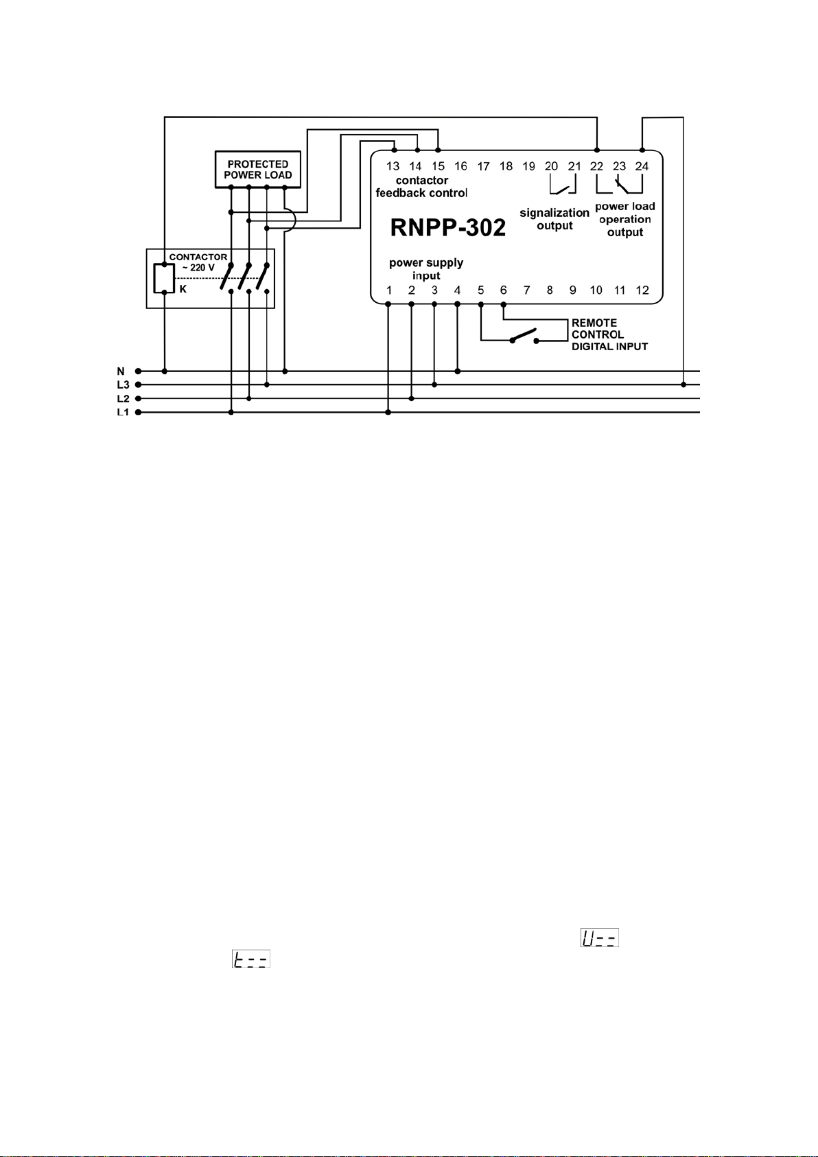
Connect the contactor (magnetic starter) to the RNPP-302 and mak e all other necessary connections as
shown on Figure 2
Connect mains power supply to the input terminals of RNPP-302
Turn ON the power and adjust all required settings according to Table 2
NOTE. All wiring connections must be performed on the dead device.
3. RNPP-302 SETTINGS AND CONTROLS
3.1. At the initial state on the front panel the following information is shown:
- depending the operation mode phase-to-neutral voltage on each phase (L1, L2, L3) if the parameter
Υ01= 0 or alternatively phase-to-phase voltage (L1-L2; L2-L3; L3-L1) if parameter Υ01=1;
- Phase Indicator (indicator of the currently measured phase (L1, L2 or L3));
- Operational state of the output relay (Open/Closed)
To select the phase manually
measurement values on phases are displayed in turns automatically every 5 seconds
3.2. To view and change the parameters it is necessary press SET button and all phase indicators will light
up. To scroll between the parameters use DOWN and UP but tons. To enter the parameter and chance value
press SET button. Then using DOWN and UP buttons set the desired values. To save the paramet er and exit
the current menu press WR button. To exit the menu without saving press SET button. If none of the buttons
are pressed within 15 seconds the RNPP-302 returns to initial state.
(ιιΥ=0) use DOWN and UP buttons, alternatively if parameter ιιΥ=1 the
NOVATEK-ELECTRO
RNPP
-302
Page 4
- 4 -
3.3. To restore default factory settings quickly it is necessar y to press simultaneously SET, DOWN and UP
buttons and energize the RNPP-302 while keeping these buttons pressed. Then the display should indicate
“
νΑΥ”. Then Turn OFF the device. Factory settings are restored.
Figure 2. Wiring diagram of the RNPP-302 to the 4 wires power circuits (with neutral phase present).
NOTES. In case the RNPP-302 is installed in 3 wires power circuit (without neutral) the connection of the
Neutral Phase (Terminal #4) is optional (neutral may not be connected).
On the wiring diagram 220V contactor is shown like the example, if the connection of 380V contactor is
necessary contactor coil “K” should be connected to L1 or L2 phases.
4.
RNPP-302 OPERATION
4.1. Modes of RNPP-302 operation.
Depending on the
1) Phase loss relay (the relay monitors only the presence of voltage (not the voltage level) on every
phase)
τΠρ =0;
2) Minimal voltage monitoring relay τΠρ =1;
3) Maximal voltage monitoring relay τΠρ =2;
4) Over/Under voltage monitoring (min/max) mode τΠρ =3 ;
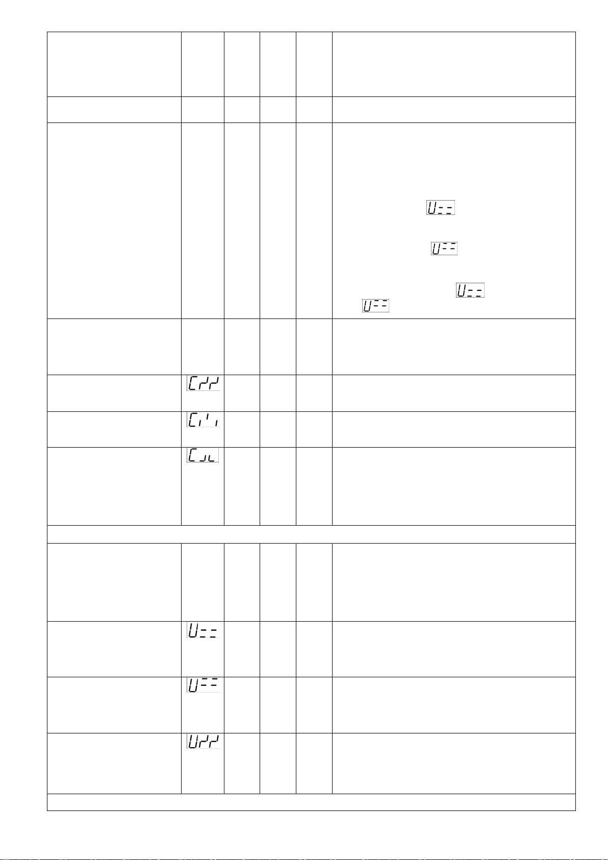
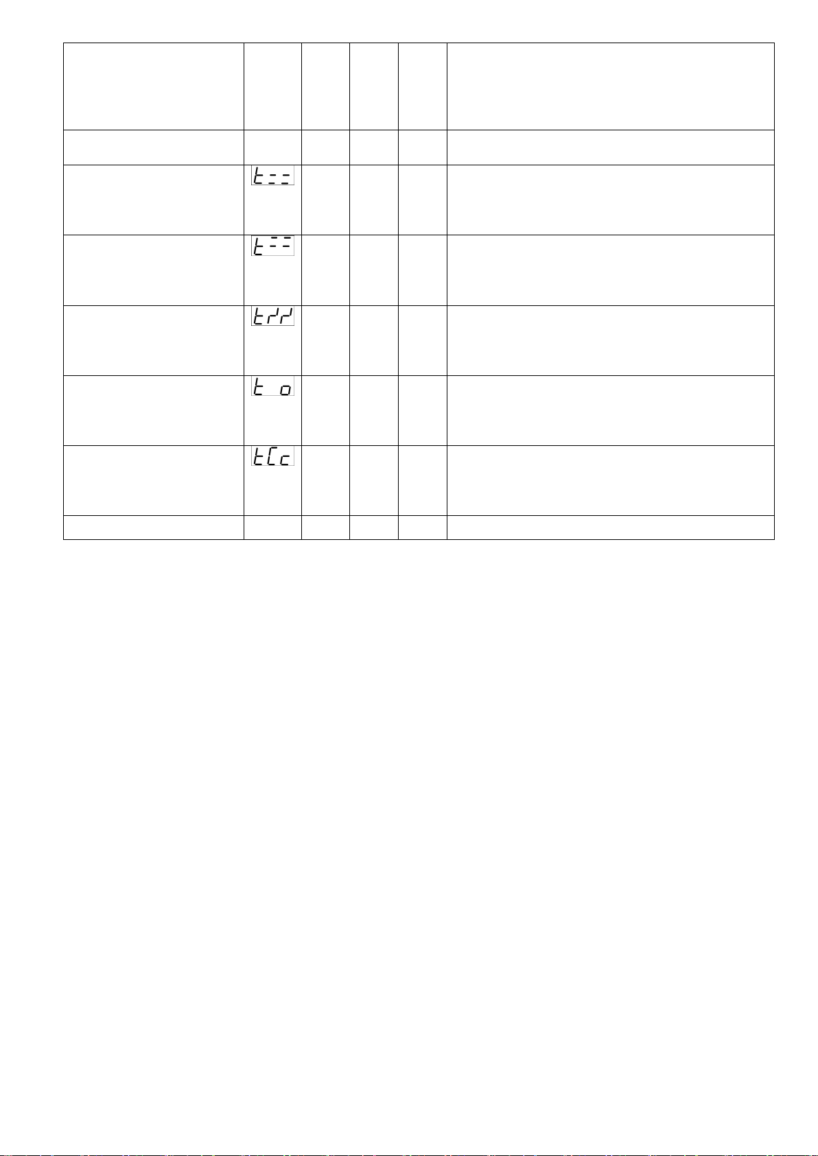
Modes of operation, adjustable parameters, time delays and other controls are shown in Table 2.
4.2. Voltage monitoring modes
4.2.1 First start up instructions
In case of first start up during the inst allation or if the RNPP-302 was deenergized on first turning ON it is
necessary to add 0,3-0,4 seconds to the automatic reclosing time delay (
necessary for preparation to work and for self-testing of the RNPP-302.
4.2.2. Minimal voltage monitoring mode (τΠρ =1)
If the RNPP-302 was initially in turned OFF s tate then in case the c orrect voltage is applied to the device it
will automatically turn ON within the delay time defined by
terminals 23,24 will open while 22,24 and 20,21 will close.
If the input voltage get lower than the minimal tripping threshold (parameter
defined by user (parameter
close while 22,24 and 20,21 will open.
RNPP-302 has the operative acceleration in turn OFF time. If the voltage decrease is more than 80 V
regardless of the preset voltage tripping threshold the RNPP-302 will cut OFF the power load within
0,1 second.
After the recovery of the voltage parameters – when controlled voltage becomes 5-6 V higher than minimal
tripping threshold (voltage hysteresis is 5-6 V) the relay will automatically turn ON the power load with delay
time defined by
τΠΠ parameter.
τΠρ parameter value the RNPP-302 can work in following modes:
τΠΠ parameter). This time is
τΠΠ parameter: the “REL” LED will light up and
) within the curtain time
) – then the RNPP-302 will turn OFF the power load: terminals 23,24 will
RNPP-302
NOVATEK-ELECTRO
Page 5
- 5 -
4.2.3. Maximal voltage monitoring mode (τΠρ =2)
In this mode power load should necessarily be connected to terminals 23,24.
When giving correct power supply to the input of the RNPP-302 the position of the output contacts don’t
change and correspond to “cold state”: terminals 23,24 are closed while 22,24 and 20,21 are open.
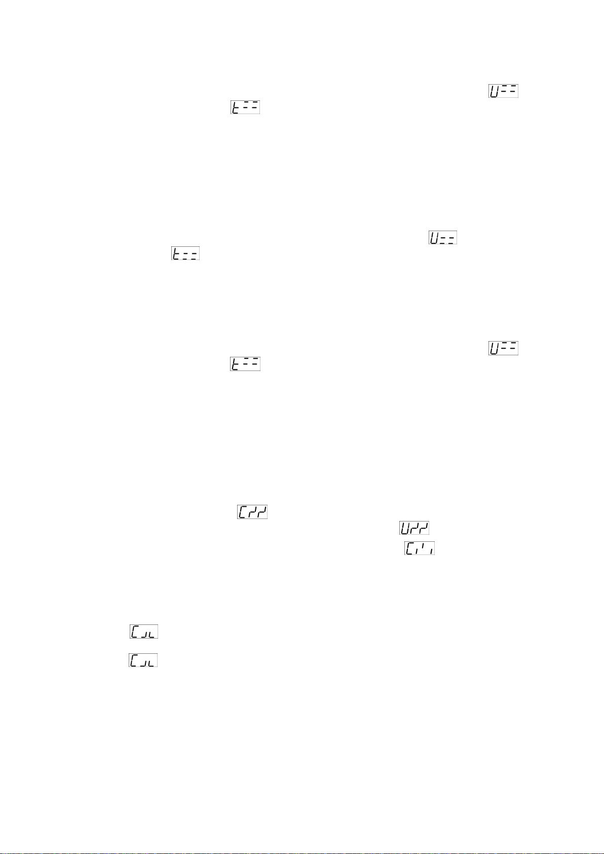
If the increase in input voltage is more than the maximal tripping threshold (parameter
curtain time defined by user (parameter
) – then the RNPP-302 will turn OFF the power load: terminals
23,24 will open while 22,24 and 20,21 will close.
After the recovery of t he voltage parameters – when controlled voltage becom es 5-6 V lower than maximal
tripping threshold (voltage hysteresis is 5-6 V) the relay will automatically t urn ON the power load with delay
time defined by
τΠΠ parameter.
4.2.4. Over/Under voltage monitoring (min/max) mode (τΠρ =3)
If the RNPP-302 was initially in turned OFF state then in case the correc t voltage is applied to t he device it
will automatically turn O N within the delay time defined by
τΠΠ parameter: the “REL” LED will light up and
terminals 23,24 will open while 22,24 and 20,21 will close.
If the input voltage get lower than the minimal tripping threshold (parameter
defined by user (parameter
) – then the RNPP-302 will turn OFF the power load: terminals 23,24 will
) within the curtain time
close while 22,24 and 20,21 will open.
If the voltage decrease is more than 80 V regardless of the preset voltage tripping threshold the RNPP-302
will cut OFF the power load within 0,1 second (accelerated turn OFF).
After the recovery of the voltage parameters – when controlled voltage becomes 5-6 V higher than minimal
tripping threshold (voltage hysteresis is 5-6 V) the relay will automatically t urn ON the power load with delay
time defined by
τΠΠ parameter.
If the increase in input voltage is more than the maximal tripping threshold (parameter
curtain time defined by user (parameter
) – then the RNPP-302 will turn OFF the power load: terminals
23,24 will close while 22,24 and 20,21 will open. After the recovery of the voltage parameters – when
controlled voltage becomes 5-6 V lower than maximal tripping threshold (voltage hysteresis is 5-6 V) the relay
will automatically turn ON the power load with delay time defined by
τΠΠ parameter.
4.3. Control of the additional voltage parameters
In all above stated modes of operation the RNPP-302 performs permanent control over additional voltage
parameters and in case of deviation from the preset values it turns OFF the power load and turns ON the
alarm signalization. On the recovery of voltage level and cancel of the alar m situation RNPP-302 will turn ON
the power load after the
τΠΠ time and turn OFF the signalization.
RNPP-302 performs the control over following parameters:
1) Phase imbalance. If the parameter
and the tripping threshold for the phase imbalance is defined by parameter
=1 the RNPP-302 performs the control over phase imbalance
.
2) Wrong phase sequence and phase combination. If the parameter =1 RNPP-302 monitors the
correct phase sequence and the absence of the phase combination.
3) Feedback control of the voltage presence on the contactor (magnetic starter) terminals. If the contactor
has burned or stuck contacts – RNPP-302 will cut the output relay and turn ON the alarm signalization. This
function is of a great importance as the equipment could be damaged due to bad or damaged contactor
whereas all input voltage parameters are fine and correct.
If the parameter
=1 the RNPP-302 detects the presence of the voltage on the output terminals of the
contactor and in case the stuck contacts it turns OFF the power load and turns ON the alarm signalization.
If the parameter
=2 the RNPP-302 checks the voltage presence on the output contactor contacts and
allows all contacts to be opened (full-phase disconnection is permitt ed). The alarm situat ion is detected only in
case one or two contacts of the contactor are opened. So it may be the situation when only one or two phases
will come to the equipment because of a damaged or not properly working contactor and this m ay result to t he
damage of the equipment or installation. This function is essential when the equipment or power load need to
be switched ON/OFF using the remote control switch or additional technological contact.
To restart the operation of the RNPP-302 again after the detection of wrong phase sequence or the
absence of voltage on the contactor output terminals it will be necessary to eliminate the reason of the
power interruption, then reconnect the RNPP-302 and then turn ON the power supply.
) within the
) within the
NOVATEK-ELECTRO
RNPP
-302
Page 6
- 6 -
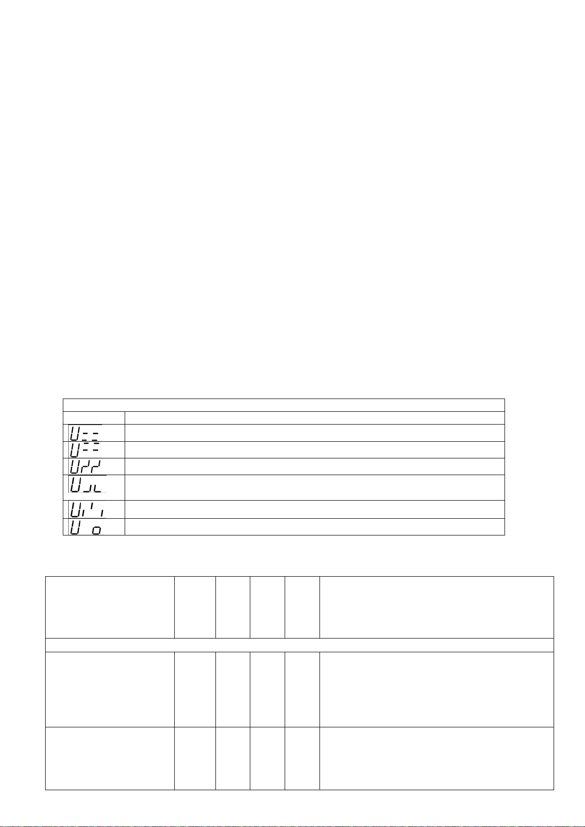
Signalization codes shown on display
А1
Digital input Turn OFF remote control
Minimal voltage
Phase imbalance
The absence of voltage on the contactor output terminals or in case of not full
phase switching of the contactor
Wrong phase sequence
Phase loss
Parameter
Basic parameters and SETTINGS
Voltage measurement
0 1 1
0 - Manual phase selection. It is displayed the
every 5 sec
Digital input signal to
χΧ1
0 2 0
0 - not enabled
2 - on opening of the digital input contact the
4) Control of the external signals coming to the digital input. It is defined by parameters χΧ1= 1 (χΧ1=2).
RNPP-302 has the digital input that may be used to detect the external alarm sit uation (for example the signal
from thermostat built into the AC motor coil). On getting the signal the RNPP-302 immediately disconnect the
power load and displays the “A1” alar m code. When the alarm situation is eliminated (there is no signal from
the external source) the RNPP-302 will automat ically turn on the power load with the delay time defined by
τΠΠ parameter.
4.4. Indication
In the absence of the alarm situations on the LED display of RNPP-302 it shown the value of acting voltage
(RMS voltage) on the selected phase marked by phase indicator (please see Figure 1).
“REL” LED indicator shows the ON/OFF state of the output relays of RNPP-302. If “REL” LED lights that
mean that the relay is turned ON. During the countdown of the autoreclosing time delay LED indicator REL will
blink in case of the normal power parameters. Time countdown of the autoreclosing delay starts from the
moment of the fault detection (not from the moment when the power parameters recovered to their
corresponding rated values).
In case the power interruptions in minimal voltage, m aximal voltage, phase loss and phase imbalance the
corresponding LED will light up to mark the phase where the interruption happened.
If the wrong phase sequence was detected by RNPP-302 all red LEDs will light up in t urn s.
On all other alarm situations all red LEDs will light permanently.
All codes of the alarm situation are shown on the LED display according to the Table 1.
4.5. Signalization
Signalization relay output turns ON/OFF simultaneously with the main output relay that operates with the
power load. This allows to use signalization relay for the operation by the contactor also. So the main output
relay could be used as a signalization relay with normally closed contacts (contacts are closed when there is
no alarm situation).
Table 1 - ALARM CODES
Maximal voltage
Table 2 - RNPP-302 OPEATION MODES
Adjustable and
measures parameters
indication
codes
ιιΥ
Minimal
value
Maximal
Value
Factory
setting
voltage on the phase which is marked by Phase
Indicator.
1 - Automatic Phase Selection. Voltage measurements on each phase are shown in turns
Description
turn O FF the RNPP-302
relay remotely
RNPP-302
1 - on closing of the digital input contact the
RNPP-302 immediately turns OFF the power
load
NOVATEK-ELECTRO
Page 7
- 7 -
Parameter
RNPP-302 immediately turns OFF the power
load
Mode of RNPP-302
τΠρ
0 3 3
0 - PHASE LOSS RELAY (minimal and maxi-
Method to set Voltage
ΣΥρ
0 1 0
0 - voltage values are set up in absolute
Phase imbalance control
0 1 1
0 - not enabled
Phase sequence control
0 1 1
0 - not enabled
Control of the voltage
0 2 0
0 - not enabled
stop/start function is required)
Voltage setting
Voltage measurement
Υ01
0 3 0
0 - phase voltage (phase-to-neutral) 220V
5 - line voltage (phase-to-phase) 415V
Minimal voltage setting,
85
230
180
ΣΥρ
Υ01
Υ01
Υ01
ΣΥρ
Υ01
Υ01
Υ01
ΣΥρ
Υ01
Maximal voltage setting,
235
295
245
ΣΥρ
Υ01
Υ01
Υ01
ΣΥρ
Υ01
Υ01
Υ01
ΣΥρ
Υ01
Phase imbalance, V:
10
80
15
ΣΥρ
Υ01
Υ01
Υ01
ΣΥρ
Υ01
Υ01
Υ01
ΣΥρ
Υ01
Time setting
Adjustable and
measures parameters
operation
deviation
Description
codes
Minimal
value
Maximal
Value
Factory
setting
mal voltage are not controlled), RNPP-302
turns OFF the power load only if voltage
disappear on 1 or 2 phases;
1 - MINIMAL VOLTAGE RELAY, RNPP-302
turns OFF the power load if the voltage gets
lower than preset
value;
2 - MAXIMAL VOLTAGE RELAY, RNPP-302
turns OFF the power load if the voltage gets
higher than preset
value;
3 - MINIMAL/MAXIMAL VOLTAGE RELAY,
RNPP-302 turns OFF the power load if the
voltage gets lower than value or higher
than
value
values
1 - voltage values are set up in % of rated
power parameters
presence on the output
contacts of the contactor
V:
In % values
V:
In % values
In % values
NOVATEK-ELECTRO
147
-60
407
-10
17
5
398
+10
510
+20
138
35
311
-30
424
10
25
5
1 - enabled
1 - enabled
1 - enabled
2 - enabled, and full-phase TURN OFF or
TURN ON of the contactor is allowed (for
example for the cases where manual
1 - phase voltage (phase-to-neutral) 230V
2 - phase voltage (phase-to-neutral) 240V
3 - line voltage (phase-to-phase) 380V
4 - line voltage (phase-to-phase) 400V
If
If
If
If
If
If
If
If
=0 and
=0 and
=1 and any values of
=0 and
=0 and
=1 and any values of
=0 and
=0 and
=0,
=3,
=0,
=3,
=0,
=3,
=1,
=4,
=1,
=4,
=1,
=4,
=2;
=5;
parameter.
=2;
=5;
parameter.
=2;
=5;
If
=1 and any values of
RNPP
parameter.
-302
Page 8
- 8 -
Parameter
Autoreclosing time
delay, sec
τΠΠ
0,5 600
10
Time delay to TURN OFF
interruption detected, sec
0,1
30
10 Time delay to TURN OFF
interruption detected, sec
0,1
30
1
the power load in case the
detected, sec
Time delay to TURN OFF
load in case the
sec
0,1
30
0,5
Time delay to TURN OFF
the power load in case the
the digital input, sec
0,1
600
10
Device version
ρΕΛ
12
Adjustable and
measures parameters
the power load in case of
minimal voltage
the power load in case of
maximal voltage
Time delay to TURN OFF
phase imbalance is
the power
phase loss is detected,
codes
Minimal
value
0,1 30 3,0
Description
Maximal
Value
Factory
setting
alarm signal comes from
5. STORAGE AND SHIPPING CONDITIONS
The RNPP-302 in manuf acturers package should be stored in enclosed rooms with ambient temperature
from -45° to +75° C and exposed to not more than 80% of relative humidity. It should be no f umes in the air
that may exert a deleterious effect on package and the RNPP-302 components. The Buyer must provide the
protection of the relay against possible mechanical damages in transit.
6. WARRANTY
Novatek-Electro LTD. company warrants a trouble-free operation of the RNPP-302 device within 36
months from the date of sale, on condition that following terms are provided:
-- the proper connection;
-- the safety of the inspection quality control department seal;
-- the integrity of the case, no traces of an opening, cracks, spalls etc.
RNPP-302
NOVATEK-ELECTRO
 Loading...