

Page 1
NOVATEK-ELECTRO LTD
Research-and-Manufacture Company
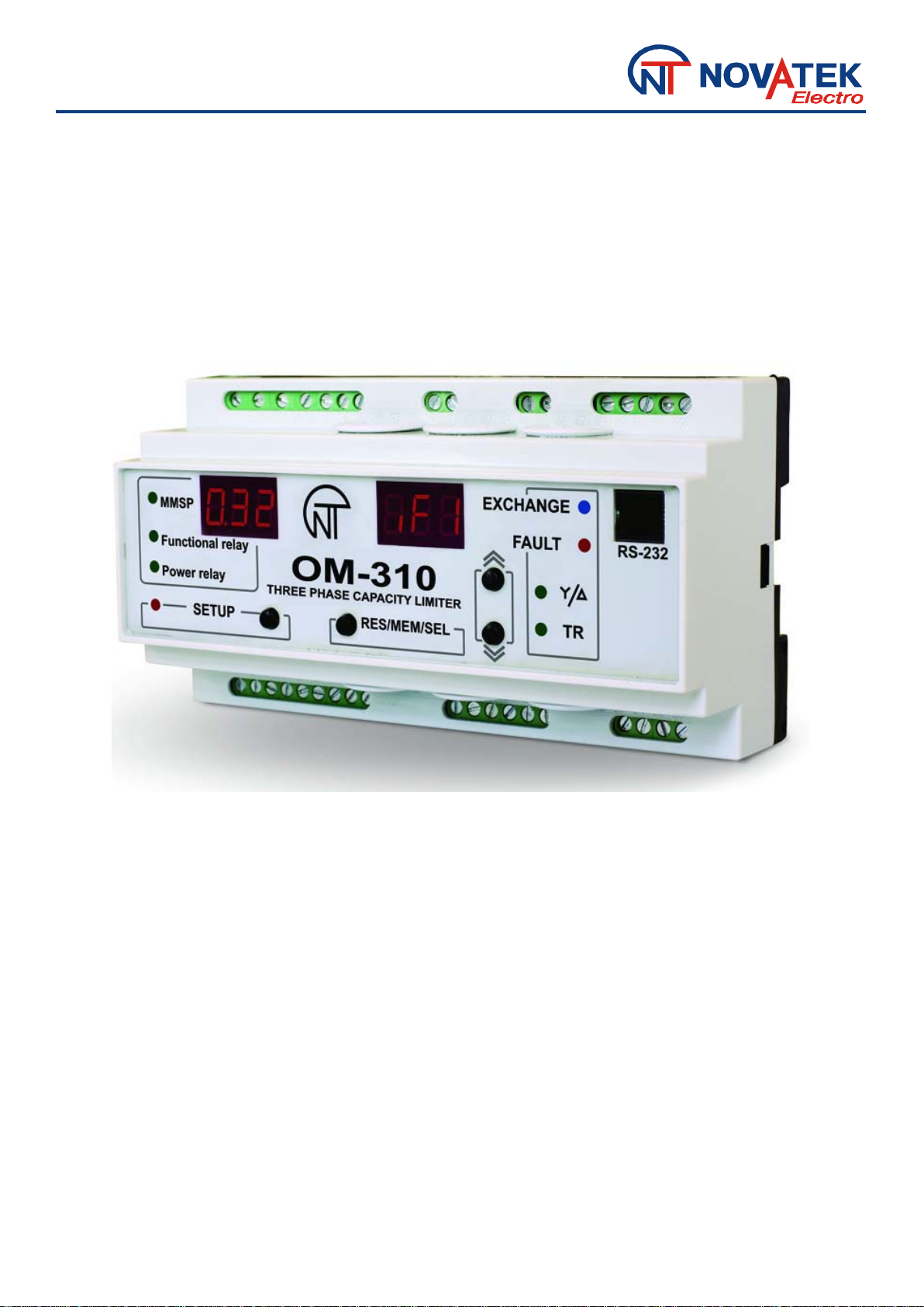
POWER LIMITER
OM-310
USERS MANUAL
www.novatek-electro.com
Page 2

- 2 -
CONTENT
1. DESCRIPTION AND OPERATION .................................................................................................................................... 3
1.1 APPLICATIO N .............................................................................................................................................................. 3
1.1.1 OM-310 power limiter is designed for the following applications: ......................................................................... 3
1.1.2 OM-310 application limitations and proper selection of parameters ..................................................................... 3
1.1.3 Integrated relays output terminals specification .................................................................................................... 4
1.1.4 List of abbreviations used ..................................................................................................................................... 4
1.2 TECHNICAL BRI EF ...................................................................................................................................................... 4
1.2.1 Basic technical parameters .................................................................................................................................. 4
1.2.2 Measured and calculated parameters .................................................................................................................. 4
1.2.3 Programmable parameters and their variability ranges ....................................................................................... 6
1.2.4 Operating controls and the dimensions of the ОМ-310 ....................................................................................... 9
1.2.5 Power Limiting Functions .................................................................................................................................... 10
1.2.6 Protection functions ............................................................................................................................................ 12
1.3 PRODUCT PACKAGE CONTENTS ........................................................................................................................... 13
1.4 EQUIPMENT FEATURES AND OPERATION ........................................................................................................... 13
2. INTENDED USE ............................................................................................................................................................... 13
2.1. SAFETY ..................................................................................................................................................................... 13
2.2 ОМ-310 DEVICE CONTROL ...................................................................................................................................... 13
2.2.1 Control Modes ..................................................................................................................................................... 13
2.2.2 Disabled keypad mode ........................................................................................................................................ 14
2.2.3 MMSP mode ...................................................................................................................................................... 14
2.2.4 User level ........................................................................................................................................................... 14
2.2.5 Service Engineer Level ....................................................................................................................................... 14
2.2.6 Restoring factory settings. .................................................................................................................................. 15
2.3 OM-310 PRE-OPERATION PROCEDURE ................................................................................................................ 15
2.4 INTENDED USE ......................................................................................................................................................... 16
2.4.1 ОМ-310 operation before load relay closure ...................................................................................................... 16
2.4.2 OM-310 operation before load relay closure ....................................................................................................... 17
2.4.3 Characterizing relay operation ............................................................................................................................ 17
2.4.4 Work with RS-232/RS-485 interface under MODBUS protocol in RTU mode. ................................................... 17
2.4.5 The load energize/de-energize remote control via RS-232/RS-485 interface. .................................................. 21
2.4.6 Load energize/de-energize via remote breaker .................................................................................................. 22
2.4.7 Fault conditions system ....................................................................................................................................... 22
2.4.8 Faulty conditions log .......................................................................................................................................... 22
2.4.9 Load start/cutoff control with use of OM-310 front panel .................................................................................... 23
3. MAINTENANCE ............................................................................................................................................................... 24
3.1. SAFETY ..................................................................................................................................................................... 24
3.2 MAINTENANCE SCHEDULE ..................................................................................................................................... 24
4. TRANSPORTATION AND STORAGE ............................................................................................................................. 24
5. PERIOD OF SERVICE, STORAGE, AND MANUFACTURER’S WARRANTY .............................................................. 24
6. ACCEPTANCE CERTIFICATE ...................................................................... ОШИБКА! ЗАКЛАДКА НЕ ОПРЕДЕЛЕНА.
APPENDIX 1- DEPENDENT TIME DELAY CURRENT BASED PROTECTION TYPES: ................................................. 25
ОМ-310
NOVATEK-ELECTRO
Page 3

- 3 -
1. DESCRIP TION AND OPERATION
1.1 APPLICATION
1.1.1 OM-310 power limiter is designed for the following applications:
- load protection at poor p ar ameters of the mains;
- complete load cutoff in c ase i f w at t s input exceeds the main threshold wit hi n t he use r-set time period;
- partial load cutoff in case if wat t s inp ut exce eds the additional threshold wit hi n t he user-set time period;
- measurement and indication of 3-phase electric circuit (delta voltage and mesh voltage RMS values; positive
phase, negative phase and zero phase sequence voltages; phase currents RMS values; input wattage of active
power, wattles power, appar ent power, power factor (cos ϕ))
- fault warning;
- remote load on and off via RS-232/RS485 interface or and ext er nal switch.
OM-310 provides for operation under loads ranging from 2,5 kW to 30 kW with use of integrated current transfor-
mers, and up to 350 kW at use of external current transformers, including when in networks with insulated neutral.
OM-310 device provides the following types of load pr ot ection:
- when the mains voltage is of poor quality (impermissible voltage surges, phase loss, incorrect phase sequence and phase "coincidence", phase/line voltage i mba la nce );
- when maximum specified cu rr ent in any load phase is exceeded;
- against “ground” leakage currents;
For each separate type of pr ot ection, the unit allows to enable or disable automatic load reset (further : AR)
OM-310 provides electric equ ipment protection by means of a ma gnet ic starter (contactor) coil control.
OM-310 the user has possibility to choose functionality of additional relay and use it for following operations:
Using
-signalization emergency situations
- contactor connection of additional loading
-as time relay
-signalization of reactive power excess
-signalization of active power excess
Communication
ОМ-310 provides for:
- control and parameters t r ansfer via RS-485 interface accor di ng t o M O DBUS protocol,
- control and parameters transfer via RS-232 interface.
N o t e: Simultaneous use of RS-48 5 and RS-232 is not possible.
Interaction of PC and OM-310 is possible via "OM-310 Co nt r ol Panel” Software that can be downlo aded from
the “Novatek-Electro” website (http://www.novatek-electro.com/production_ом.htm).
OM-310 Control Panel software is dedicated for monitoring status and retrieving data from OM-310 devices via standard communication inter f ace (RS-232 or RS-485). The Software allows for saving (loading) various
retrieving data and saving them for further research. The user can view sa ved data in a graph, while compar ing parameters.
The CP graphic environ m ent all ow s f or r eal-t ime viewing the current status of various OM-310 parameters.
The flexible interface design allows t uning it to any user’s preferences.
1.1.2 OM-310 applicati on limitations and proper sel ect ion of parameters
1.1.2.1 Use of integrate d cur r ent t r ansformers.
Attention! OM-310 cannot be used for protect i on of load with wattage over 30 kW.
When measuring load currents from 63A to 300A, the measurement error does not exceed 5% , w hile at currents
over 320A, the current transformer core saturation starts, and the measurement error increases rapidly. Regardless
In spite of the actual current value, the current measured by OM-310 will not exceed 400A. Setting up certain programmable parameters (maximum current protection) without regard to current transformers saturation will make
protection tripping impossible.
For example, at “
”=50 (load rated current), =0 (ratio of independent delay current protection), =9
(maximum current protection tripping), the maximum current protection would have tripped at current value of 450А.
Due to current transformer saturation, the measured current value will not exceed 380-400A, even in case of a short
circuit from the load side, and currents of over 1000A, and, therefore, ОМ-310 will no t de-energize the load. In such
case (“
”=50) the user shall set the overcur r ent t r ipping ratio to not more than 6.
1.1.2.2 Use of external currents transformers.
In case of tested standard transformer samples, the core saturation took place at 4-5 times the rated current
value. Therefore, to provide for proper functioning of ОМ-310 protections, one should select external transformers
with rated current value exceeding the rated load currents twice and more, or choose parameters considering the
saturation.
OM-310 settings,
NOVATEK-ELECTRO
ОМ-310
 Loading...