

NOVATEK NT6827 Datasheet

NT6827
I2C Bus Controlled On-Screen Display
1 V2.0
Features
n I2C Bus Interface with Slave Address $7A (Transmitter)
& $7B (Receiver)
n Horizontal Frequency Range: 30KHz ~ 120KHz
n Flexible Display Resolution Up to 1524 Dots/Row
n Internal PLL Generates a Stable and Wide-Range
System Clock (96MHz)
n OSD Screen Consists of Character Array of 15 Rows
by 30 Columns
n Programmable Vertical and Horizontal Positions for
OSD Display Center
n Total of 272 ROM Fonts Including 256 standard & 16
Multi-color ROM Fonts.
n 12 X 18 Dot Matrix Per Character
n 8-Color Selection for Each Character
n 7-Color Selection for Each Character Background
n Character/Symbol Blinking, Shadowing & Bordering
Display Effect
n Double Character Height and Width for Each Row
n Programmable Height for Character/Symbol Displaying
n Row To Row Spacing Control to Avoid Expansion
Distortion
n Four Programmable Windows with Overlapping
Capability and Shadowing Effect
n Color Setting for Windows’ Background and
Characters’ Shadowing & Bordering
n Fade-In/Out Effect of OSD Screen Display
n Selectable Hsync & Vsync Input Polarity
General Description
NT6827 is designed for displaying symbols and characters
onto a CRT monitor. Its operation is controlled by a microcontroller with an I2C bus interface. By sending proper
data and commands to NT6827, it can carry out the full
screen display automatically with the time base being
generated by an on-chip PLL circuit. There are many
functions provided by this chip to fully support the user
applications, such as: adjustment of the OSD windows
position, built-in 256 ROM & 16 Multi-color fonts, variable
character height with row-to-row spacing adjustment, 8
color selections & 7 background color controls for each
character, double height/width controls for each row, 4
overlapping windows available with color & size controls,
size controls for each window shadowing, color selection
for windows’ shadowing & characters’ shadowing/
bordering and fade-in/out display effect ,etc.

NT6827
2
Block Diagram
I2C
BUS
RECEIVER
SCL
SDA
VSYNC
VFLB
HSYNCHFLB
VPOL
HPOL
DISPLAY
MEMORY
CONTOL
REG.
ROM
FONT 12 * 18
OUTPUT
CONTROL
R/G/B
FBKG
PWM /
HFTON
POWER
SYSTEM
AVCC
POWER ON
LOW VOLTAGE
RESET
TIMING
GENERATOR
DVCC
AGND
DGND
VERTICAL
CONTROL
PLL
CIRCUIT
RP
VCO
HORIZONTAL
CONTROL
BUS CONTROL
BUFFER
DISPLAY
EFFECT
COLOR
CONTROL
TEST
CIRCUIT

NT6827
3
Pin Assignment
1
2
3
4
5
6
7
8 9
10
11
12
16
15
14
13
AGND
VCO
RP
AVCC
HFLB
N.C.
SDA
SCL
DGND
R
G
B
FBKG
PWM / HFTON
VFLB
DVCC
NT6827

NT6827
4
Pin Description
NT6827 Name I/O/P/R Function
1 AGND P Analog Ground
2 VCO - Voltage I/P to Control Oscillator
3 RP -
Bias Resistor. It is used to bias internal VCO to resonate at the
specific dot frequency.
4 AVCC P Analog Power Supply (5V Typ)
5 HFLB I Horizontal Fly-back Input (Schmitt Trigger Buffer)
6 N.C. - -
7 SDA I
SDA Pin Of I2C Bus (Schmitt Trigger Buffer) with internal 100K ohm
pulled-high resistance
8 SCL I
SCL Pin Of I2C Bus (Schmitt Trigger Buffer) with internal 100K ohm
pulled-high resistance
9 DVCC P Digital Power Supply (5V Typ)
10 VFLB I Vertical Fly-back Input (Schmitt Trigger Buffer)
11
PWM/
HFTON
O PWM output or gain controller of R, G, B channels.
12 FBKG O Fast Blanking Output. It is used to cut off the external R, G, B signals.
13 B O Blue Color Output with Push-Pull Output Structure
14 G O Green Color Output with Push-Pull Output Structure
15 R O Red Color Output with Push-Pull Output Structure
16 DGND P Digital Ground

NT6827
5
DC/AC Absolute Maximum Ratings*
Recommended Operation Conditions
VCC (measured to GND) . . . . . . . . . . . . 4.75V to 5.25V
Operating Temperature . . . . . . . . . . . . . . 0 to +70 0C
*Comments
Stresses above those listed under "Absolute Maximum
Ratings" may cause permanent damage to this device.
These are stress ratings only. Functional operation of
this device at these, or under any other conditions above
those indicated in the operational sections of this
specification is not implied or intended. Exposure to the
absolute maximum rating conditions for extended
periods may affect device reliability.
Electrical Characteristics (VDD = 5V, Tamb = 25°C)
Symbol Parameter Min. Typ. Max. Unit Notes
VCC Supply Voltage 4.75 5 5.25 V -
DC Characteristic
Symbol Parameter Min. Typ. Max. Unit Notes
IDD
Operating Current - 22 25 mA No loading
VIH1 Input High Voltage 2 - - V
VFLB, HFLB with
Schmitt Trigger Buffer
VIL1 Input Low Voltage - - 0.8 V
VFLB, HFLB Schmitt
Trigger Buffer
VIH2 IIC Bus Input High Voltage 3 - - V
VIL2 IIC Bus Input Low Voltage - - 1.5 V
SCL, SDA
Idrive1
Driving current of R, G, B, FBKG, HFTON
output pins at 2.4V output voltage
80 - - mA -
Isink1
Sinking current of R, G, B, FBKG, HFTON
output pins at 0.4V output voltage
20 - - mA -
Ileak
Leakage current of R, G, B, FBKG pins at
Hi-Z state
- - 10 uA Measured at 2.5V state
Iiicl IIC Bus Output Sink Current - 5 - mA Viicoutl = 0.4V
Vth Input Threshold Voltage at HFLB & VFLB pin 1.8 2.0 2.2 V -
VSTIH Schmitt Trigger Input High Voltage 1.7 2 V -
VSTIL Schmitt Trigger Input Low Voltage 0.8 1.1 - V -
Iin Input Current of Hsync, Vsync, SDA, SCL pins -10 - +10 uA Schmitt Trigger Buffer
NT6827
6
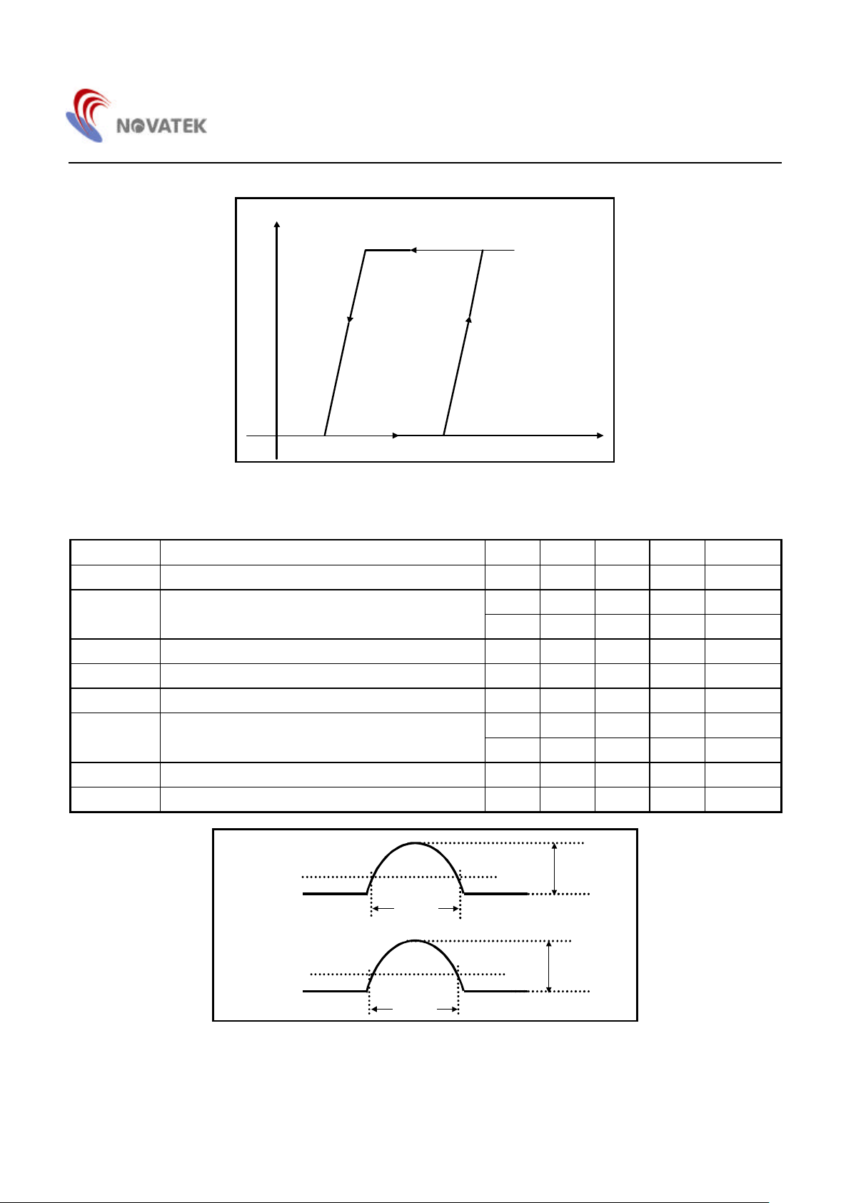
1.1V
1.7V
VH
VL
Output state
Input voltage
Figure 1. Schmitt Trigger Diagram
AC Characteristic
Symbol Parameter Min. Typ. Max. Unit Notes
Fhfy Horizontal Fly-back Frequency 30 - 120 KHz -
- - 5 V -
Vhfly Horizontal Fly-back Input
0 - - V -
Thflymin Minimum Pulse Width of Horizontal Fly-back 0.7 - - us -
Thflymax Maximum Pulse Width of Horizontal Fly-back - - 5.5 us -
Fvfy Vertical Fly-back Frequency 50 - 200 Hz -
- - 5 V -
Vvfly Vertical Fly-back Input
0 - - V -
Tvflymin Minimum Pulse Width of Vertical Fly-back 20 - - us -
Tvflymax Maximum Pulse Width of Vertical Fly-back - - 1 ms -
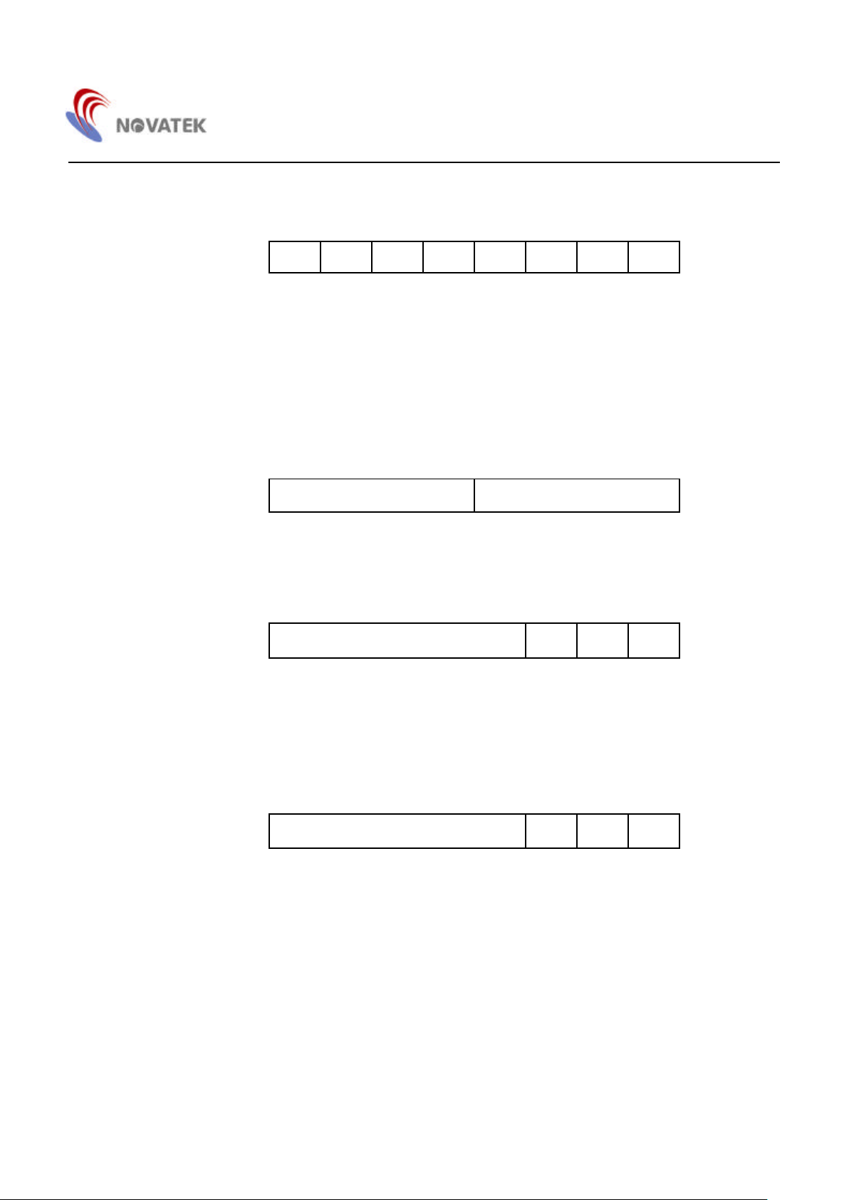
HFLB
2.0 V
Thwidth
0 V
5 V
VFLB
2.0 V
Tvwidth
0 V
5 V
Figure 2. H/V Fly-Back Signal

NT6827
7
I2C Bus– Slave Transmitter & Receiver (Slave address: $7A & $7B)
Table 1. I2C Bus
Symbol Parameter Min. Typ. Max. Unit Notes
Fmaxcl Maximum SCL Clock Frequency 100 KHz
VIL Input Low Voltage -0.5 1.5 V
VIH Input High Voltage 3.0 5.5 V
Tlow Low Period of the SCL Clock 4.7 us
Thigh High Period of the SCL Clock 4.0 us
Tsudat Data Setup Time 250 ns
Thddat Data Hold Time 300 ns
Tiicr Rising Time of IIC Bus 1000 ns
Tiicf Falling Time of IIC Bus 300 ns
Tsusta Setup Time for Repeated START Condition 1.3 us
Thdsta Hold Time for START Condition 4.0 us
Tsusta Setup Time for START Condition 4.7 us
Tsusto Setup Time for STOP Condition 4.0 us
SCL, SDA
Tiicbuf
Time the IIC bus must be free before the next
new transmission can start
4.7 us
Iiicl IIC Bus Sink Current 4 5 mA Viicoutl = 0.4 V
Tfilter Input filter spike suppression 100 ns SCL, SDA
SCL
SDA
Tiicbuf
Thdsta Tsudat
Thigh
Tiicr Tiicf
Thddat
Tlow
STOP START
Tsusta
Thdsta
STOP
Tsusto
START
Figure 3. I2C Bus Timing

NT6827
8
Memory Map
29
14
07 07
Row Attribute Register
ROW ATTRIBUTE REGISTER
ROW
7
0
30
COLUMN
00
0
DISPLAY REGISTER
Fonts Address $00-$FF
7
Figure 4. Memory Map of Display Register (Row 0 - 14)
0 29
14
0
0
7
07
COLUMN
ROW
CHARACTER ATTRIBUTE REGISTER
Character Attribute Register
Figure 5. Memory Map of Attribute Register (Row 0 - 14)

NT6827
9
ROW
0
15
0
7
07
Window 1-4 Control Register
COLUMN
11
WINDOW1 - WINDOW4 OSD SCREEN CONTROL
12 22
0
7
07
OSD Screen Control Register
23
07
Reset Flag Control Register
Figure 6. Memory Map of Control Register (Row 15)

NT6827
10
List of Control Registers:
(1) Display Register: Row 0 - 14, Column 0 - 29
7 6 5 4 3 2 1 0
Row 0 - 14
Column 0 - 29
MSB LSB
Font’s Address $00 - $FF
Bit 7 - 0: These eight bits address one of the 256 characters/symbols residing in the character ROM fonts.
Note that if the user clear the MCFONT bit (row 15, column 20) to ‘0’, the 0 ~ 255 will address the standard
ROM fonts, and if sets this bit to "1", the 0 ~ 239 will address the standard ROM fonts & the 240 ~ 255 will
address the multi-color ROM fonts.
(2) Character Attribute Register: Row 0 - 14, Column 0 - 29
7 6 5 4 3 2 1 0
Row 0 - 14
Column 0 - 29
BKR BKG BKB BLNK R G B
Character’s Attribute Control
Bit 6 - 4: BKR/G/B- These three bits define the color attributes of the background for the corresponding
haracter/symbol. If all three bits are cleared, no background will be displayed. Refer to the Table 8 for the
color selections.
Bit 3: BLNK - This bit enables the blinking effect of the corresponding character/symbol when set to ‘1’. The blinking
frequency is approximately 1Hz with a fifty-fifty duty cycle at 80Hz vertical sync frequency.
Bit 2 - 0: R/G/B -These three bits define the color attributes of the corresponding character/symbol. Refer to the Table
7 for the color selections.
Table 7. Character/Windows Color Selection
COLOR R G B
Black 0 0 0
Blue 0 0 1
Green 0 1 0
Cyan 0 1 1
Red 1 0 0
Magenta 1 0 1
Yellow 1 1 0
White 1 1 1
Table 8. Character/Windows’ Background Color
Selection
COLOR R G B
No Background 0 0 0
Blue 0 0 1
Green 0 1 0
Cyan 0 1 1
Red 1 0 0
Magenta 1 0 1
Yellow 1 1 0
White 1 1 1
NT6827
11
(3) Row Attribute Register: Row 0 - 14, Column 30
7 6 5 4 3 2 1 0
Row 0 - 14
Column 30
DBH DBW
Row’s Attribute Control
Bit 1: DBH- This bit controls the height of the displayed character/symbol. When this bit is set, the character/symbol is
displayed in double height.
Bit 0: DBW- This bit controls the width of the displayed character/symbol. When this bit is set, the character/symbol is
displayed in double width.
(4) Window 1 Registers: Row 15, Column 0
7 6 5 4 3 2 1 0
Row Start Address Row End Address
Row 15
Column 0
MSB LSB MSB LSB
Window 1 Row Size Control
Bit 7 - 4: These bits determine the row start position of window 1on the 15*30 OSD screen.
Bit 3 - 0: These bits determine the row end position of window 1on the 15*30 OSD screen.
7 6 5 4 3 2 1 0
Column Start Address
Row 15
Column 1
MSB LSB
WINEN SHAD
Window1 Column Size Control & Attribute Control
Bit 7-3: These bits determine the column start position of window 1on the 15*30 OSD screen.
Bit 2: WINEN - This bit enables window 1 when it is set. The default value of it is '0' after power on.
Bit 0: SHAD - This bit enables the shadowing on the window when it is set to ‘1’. The default value of it is '0' after power
on.
7 6 5 4 3 2 1 0
Column End Address
Row 15
Column 2
MSB LSB
R G B
Window1 Column Size Control & Attribute Control
Bit 7 - 3: These bits determine the column end position of window 1on the 15*30 OSD screen.
Bit 2 - 0: R/G/B - These bits control the background color of window 1. Refer to Table 7 for color selection.
Note: Window 1 control registers occupy column 0 - 2 of row 15, Window 2 from column 3 - 5, Window 3 from 6 - 8
and Window 4 from 9 - 11. The function of Window 2 - 4 control registers is the same as Window 1. Window 1
has the highest priority, and Window 4 the least. The higher priority color will take over on the overlapped
window area.
If the start address of the row/column is greater than the end address, this window will not be displayed.
An out of range setting (over the 15 row or 30 column range) will cause abnormal operation.
 Loading...