

Page 1
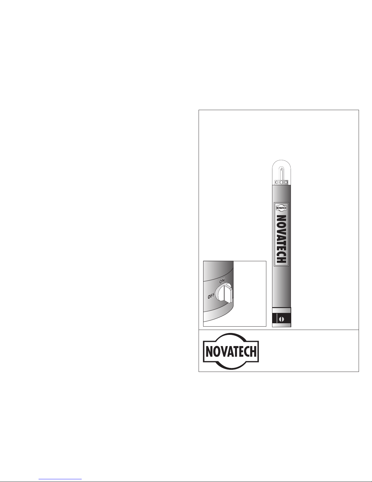
The ST-400A is
designed to assist with
locating and recovering
equipment at sea. The
is not designed
for personnel rescue or
safety and must not be
used for those
applications.
ST-400A
NOVATECH DESIGNS LTD.
271 Brownlow Ave.
D artmouth, N.S., Canada,B3B 1W6
Tel. (902) 468-7275; Fax (902) 3481-5538
e-mail: [email protected]
Web Page: www.novatechdesigns.com
ST-400A XENON FLASHER
OPERATION & MAINTENANCE MANUAL
Revised: June 2000
Copyright © 1997–2000 Novatech Designs Ltd. All rights reserved.
Pressure
Switch
with Manual
ON/OFF
Control
Innovative
design
combines
pressure
switch
and manual
on/off switch
Page 2
INTRODUCTION
The ST-400A is a self-contained submersible Xenon Flasher designed to
assist in the location and recovery of underwater oceanographic equipment.
It may be submerged for long periods in ocean depths to 7300 meters
(24,000 feet). The activation of the ST-400A is completely automatic,
when submerged below 10 meters it is OFF and at the surface it is ON at
night only.
At the surface, the ST-400A “double burst” flashes for approximately
7 days at night only and visual range is up to 3 miles at factory settings.
UNPACKING
Be sure to check shipping container for any signs of damage that might
have damaged the contents. Report any such damage to the carrier.
OPERATOR WARNINGS
PRESSURE CASE
As with any sealed pressure case, the contents could be under pressure due
to battery or seal failure. This could expel the batteries when the Pressure
Switch is removed. To be safe, always point the open end away from you
and always remove the Pressure Switch first. The Pressure Switch is designed
to vent any internal pressure when it is being removed. If a battery is trapped
in the case take extreme care, there could be a pressure buildup behind it
and the battery could be expelled at any time.
QUICK START
1. The ST-400A is shipped with batteries installed
2. Check that the Pressure Switch is secure, clockwise finger tight
3. Turn Pressure Switch knob to ON position
4. Cover lens for darkness and verify “double burst” flash
5. The ST-400A is ready to be deployed
2
ST-400A
SPECIFICATIONS
Flash Tube:
...............
Replaceable — rated for 20 x 10
6
flashes
Flash Rate:
...............
adjustable 14/minute to 60/minute ±5%
over 3 to 6 volt battery life (factory set
at 20/minute)
Visible Range:
..............
adjustable 2 to 4 nautical mile range
(0.2 to 0.6 watt-seconds) ±5% over 3 to
6 volt battery life (factory set at 3 nm
range)
Effective Intensity:
............
6 to 35 candelas
(factory set at 20 candelas)
Operating Temperature Range:
......
-40°C TO + 60°C
Ocean Depth Rating:
...........
Approx. 7,300 metres (24,000 feet)
Pressure Switch:............. Pressure activated switch turns ST-400
ON at the surface, OFF at depths below
approx. 10 metres . Manual override,
ON/OFF control knob.
Batteries: ................ 4 alkaline “C” cells
Battery Life at 4°C: Approx. 7 days, ON at night, OFF during
day at factory settings
Pressure Case Material: ......... 6061-T6 Aluminum, Hard Anodized to
Mil Spec A8625 Type 3
Weight With Batteries:
..........
In water 2.2 lb. (2.2 kg)
In air 3.7 lb. (1.7 kg)
Pressure Case Dimensions:
.......
18.5" long (470 mm), 1.7” diameter
(43 mm)
11
ST-400A
Page 3
CUSTOMER SERVICE
If you have any questions or problems, please contact the factory. We are
available to provide assistance Monday to Friday 8:00 a.m. to 5:00 p.m.
WARRANTY
Novatech Designs Ltd. guarantees this product to be free from defective
materials and workmanship and agrees to remedy any such defects for a
period of 1 year commencing from the date of purchase. The Pressure
Switch is guaranteed for 2 years, excluding corrosion damage.
This warranty does not apply if the equipment has been subject to misuse,
neglect, accident or improper installation, or altered outside our factory, or
to damage caused by defective batteries. Novatech Designs Ltd. neither
assumes nor authorizes any person to assume for it any other obligation or
liability in connection with this product, including damage resulting from
design or equipment failure.
10
ST-400A
INSTALLATION
PRESSURE CASE
When mounting the pressure case take care to prevent any side loading on
the Pressure Switch or the top end Delrin bulkhead cap. Over time, side
loading on those parts can cause a leak. Never attach anything to the 2
mounting screws on the Pressure Switch Zinc anode.
To minimize corrosion never mount the pressure case directly to metal. Isolate
the pressure case by wrapping it with vinyl tape at the contact points.
OPERATING INSTRUCTIONS
BATTERIES
The ST-400A uses 4 Alkaline “C” cells for approximately 7 days of nighttime flashing. Install fresh batteries with the positive terminal towards the
bulkhead connector. The circuit is reverse polarity protected. Rechargeable
batteries are not recommended. Always remove and discard batteries when
the ST-400A is not in use.
TURN ON & OFF
A manual ON/OFF switch is incorporated in the Pressure Switch. To turn
ST-400A ON or OFF rotate the knob as shown in Figure 1.
Figure 1. PS-200 Label
3
ST-400A
PRESSURE SWITCH PS-200
MAX. DEPTH 7300 M
PATENT PENDING
ON
OFF
Turn ON before deployment
(ON at surface, “AUTO OFF” below 10 m.
Turn OFF when not in use.
Page 4

TEST OPERATION
The following quick test verifies the ST-400A is functioning properly.
1. Turn Pressure Switch knob to ON
2. Cover the lens for darkness
3. Verify a “double burst” flashing
4. Expose lens to light, Flasher stops flashing
5. Turn Pressure Switch knob to OFF, flasher stays off in the dark
6. ST-400A is ready to be deployed.
ADJUSTMENTS
To gain access to the electronic board, remove the top cap (bulkhead
connector end) on the pressure case by rotating the black Delrin cap
counterclockwise by hand. Only hand tight when reinstalling.
CAUTION: The ST-400A generates high voltage so do not operate it
without the protective sleeve around the electronic board.
SINGLE FLASH (disable “double burst”)
Remove black jumper on lower end of PC Board (end opposite the flash
tube). Battery life will increase by approximately 30%.
ADJUST FLASH RATE
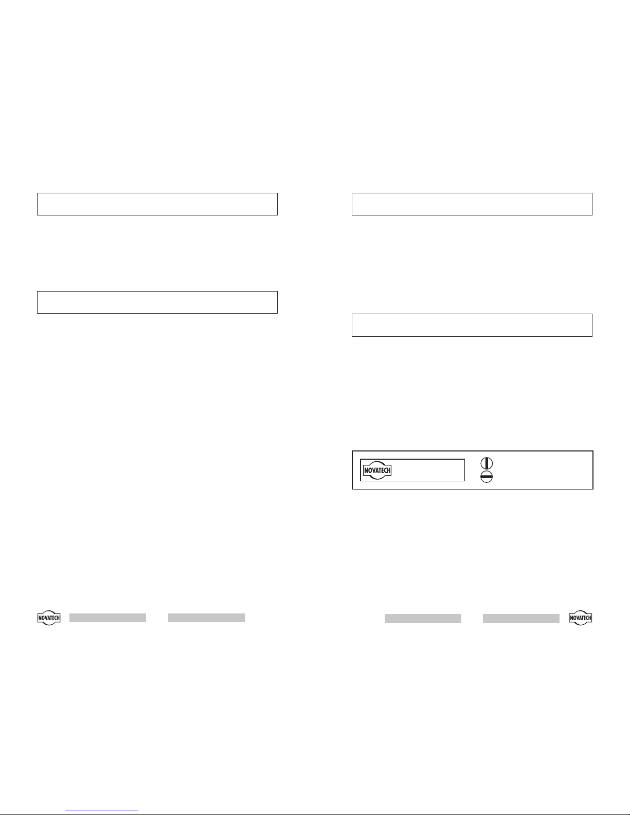
Flash rate control location is marked on the yellow label — use a small flat
screwdriver to prevent damage to the control. Higher flash rate will decrease battery life (see graph, figure 2).
ADJUST INTENSITY (VISIBLE RANGE)
Intensity control location is marked on the yellow label. Increasing inten
-
sity will decrease battery life (see graph, figure 2).
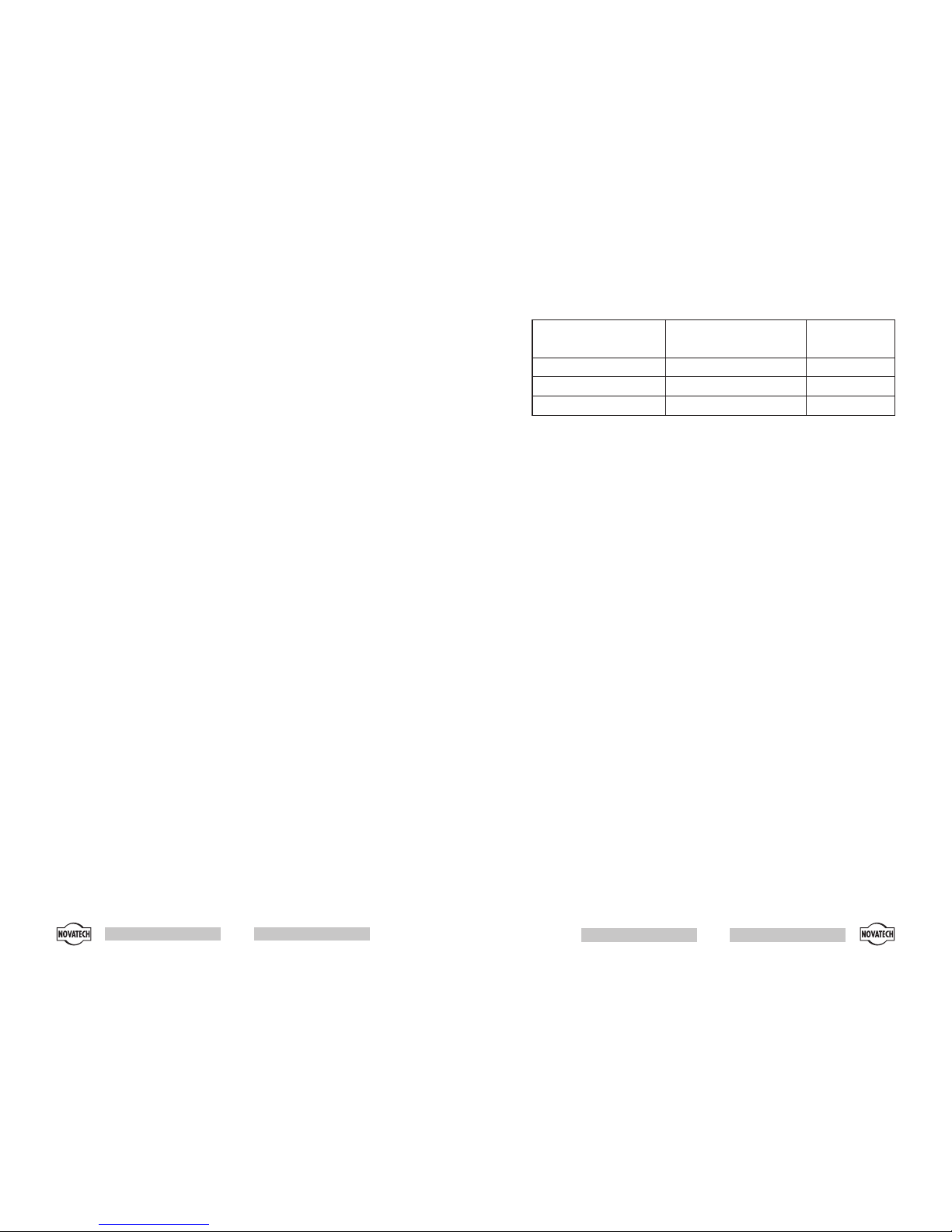
The measurement of light and the units used can be confusing and mislead
ing. The standard in the marine industry is Effective Intensity measured in
Candelas. Tests were performed in clear nighttime conditions at sea. From
the resulting data, the following table was prepared.
Note: As conditions are highly variable, your actual range may be less than
the estimates in Table 1.
4
ST-400A
4. Test the operation by pressing the Cup Seal with your finger and listen
for the micro switch clicking as you press down firmly
5. Thoroughly lubricate the outer portion of the Cup Seal
6. Make sure the Delrin Knob carrier is clean and lubricated
7. Install the Delrin carrier
8. Lubricate the two socket head cap screws
9. Install Zinc Anode and secure with the two socket head cap screws. It
will be necessary to rotate the Delrin knob carrier to line up the
threaded holes in the aluminum body
Testing
1. Install the PS-200 on your equipment
2. Make sure the Unit is ON when the PS-200 ON/OFF knob is in the
ON position
3. Make sure the Unit is OFF when the PS-200 ON/OFF knob is in the
OFF position
CORROSION PREVENTION
Corrosion is a problem common to all metals used in the ocean. To help
minimize corrosion damage, the ST-400A is made with 6061-T6 aluminum
and is hard anodized; it is also fitted with a Zinc Anode. If the Zinc is more
than 50% wasted, replace it with part no. ZN-100. If the anodized surface
is damaged, pitted or gouged, protect it against further corrosion by applying tape, paint, or fast cure epoxy.
Several precautions can be taken prior to deployment to further minimize
corrosion:
•
Do not mount the flasher against metal.
•
Wrap the entire flasher with vinyl tape. Take care not to cover the hole in
the bottom of the Pressure Switch or the Zinc Anode.
•
Prevent the anodizedsurface from being scratchedor damaged. Damage to
the anodized surface can cause pitting.
9
ST-400A
Page 5
“O” RING MAINTENANCE
Novatech strongly recommends that “O” rings be serviced on a regular basis
to ensure a reliable seal. Remove and lubricate at least once a year or
sooner and replace every two years or sooner. With regular maintenance,
“O” rings will be very reliable and trouble free. It has been, however, our
observation that most “O” rings are neglected for years and expected to
perform at the extremes of their design limits.
There are two “O” rings and a Cup Seal to service. The “O” rings are at the
top end of the Pressure Case and on the Pressure Switch, the Cup Seal is on
the Pressure Switch. Replace the two “O” rings with Parker #218 or
equivalent available from Novatech or your local “O” ring supplier. Lubri
cate lightly with a silicone grease, we recommend Parker Super O Lube.
Instructions for the lubricating or replacing the Cup Seal are below.
PRESSURE SWITCH CUP SEAL
The Cup Seal must not be overlooked when lubricating the “O” rings. The
Cup Seal should be lubricated every year and replaced every two years or
sooner. Lightly lubricate the Cup Seal by performing the following procedure:
Disassembly
1. Remove the two socket head cap screws on the Zinc Anode.
2. Withdraw the Zinc Anode and the black “Delrin” Knob Carrier.
3. Make sure the PS-200 Pressure Switch is in the upright position
(Cup Seal up, spring down); this will make sure a small internal pin
will not fall out. Do not lose that pin.
4. Carefully pry off the rubber Cup Seal, do not scratch the Cup Seal or
the mating “O” ring surface.
5. Observe the S.S. Flat Spring and note how it is installed.
Lubrication
1. Clean all surfaces and the Cup Seal.
2. Lubricate (very lightly) the “O” ring shaped portion of the Cup Seal
and the mating aluminum surface with silicone grease (Parker Super O
Lube). Do not spread the silicone grease anywhere else. Excess
silicone grease can cause the Pressure Switch to fail.
Reassembly
1. Be sure the small pin is in place
2. Place the Stainless Steel Flat Spring back in its correct position
3. Install the Cup Seal and rotate the Cup Seal ¼ turn to make sure it is
seated correctly
8
ST-400A
INTENSITY SETTING EFFECTIVE INTENSITY
(Candelas)
RANGE
nautical miles
MINIMUM 6 2.0
FACTORY SETTINGS 20 3.0
MAXIMUM 35 4.0
Table 1. Effective Intensity measured in Candelas (estimated)
BATTERY LIFE
The following graph (Figure 2) may be used to estimate the approximate
battery life for different flash rate and intensity settings. Your actual results
may vary since we have assumed 1 day is 12 hours daylight, 12 hours
night. (ST-400A operates 12 hours per 24-hour period). Your actual day to
night ratio will depend on the season and your location.
5
ST-400A
Page 6
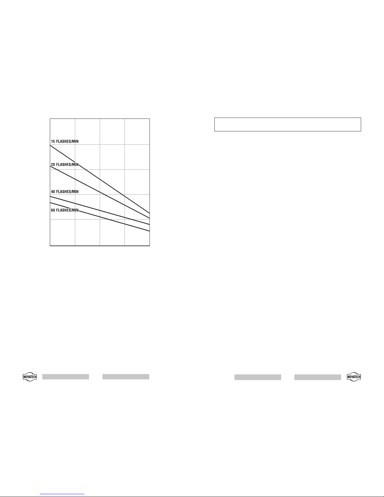
Figure 2. ST-400A — Battery Life Estimates “Double Burst Flash”
6
ST-400A
12
9
6
3
2.0 2.5 3.0 3.5 4.0
Range in Nautical Miles
Battery Life
(Days)
(ON at night
OFF during
daylight)
For single
burst
setting,
increase
battery life
by approx.
30%
MAINTENANCE
There are no user repairable parts in the ST-400A, return to the factory for
repairs.
REGULAR MAINTENANCE
•
Rinse thoroughly with fresh water after every use
•
Always remove batteries when not in use
•
Always use fresh batteries
•
Protect “O” ring surface from damage
•
Replace worn or damaged “O” rings
•
Keep batteries and electronics dry
“O” RING FACTS
“O” rings don’t last forever; two to five years is a conservative estimate.
The main problem with “O” rings is that over time they can take a “set”.
They lose their original round shape and they become slightly flattened
resulting in less squish. Reduced squish can lead to a water leak near the
surface. The best way to prevent a problem is to service the “O” rings
before every deployment.
Some of the main factors that can cause a “set” are:
•
High storage temperature(exceeding 40ºC) over timewill cause the rubber
to harden
•
Exposure to sunlight and ozone will cause the “O” ring to deteriorate and
stiffen
•
Temperature does not have to be that cold for an “O” ring to lose a great
deal of its flexibility. At 4ºC, an “O” ring has stiffened significantly.
•
“O” rings must be lightly lubricated with silicone- based grease. We rec
-
ommend “Parker Super O Lube”
•
A typical seal failure results in a very small amount of water, not a flooded
case. Most seal failures occur near the surface
•
The “O” ring becomes less flexible as the rubber ages
•
If you are operating or storing at low temperature, it makes it even more im
-
portant to service the “O” ring regularly
7
ST-400A
 Loading...