

Page 1

Timer
sales@novatech-usa.com
www.novatech-usa.com
Tel: (866) 433-6682 Fax: (866) 433-6684
Tel: (281) 359-8538 Fax: (281) 359-0084
MicroVision
MICROPROCESSOR TIMER CONTROLLER
Installation Operation Manual
72-910-23 Rev.F
Page 1 of 30
Page 2

Table of Contents
(866) 433-6682 • (281) 359-8538 • [email protected] • www.novatech-usa.com
1. INTRODUCTION ................................................................................................................................ 4
2. MICROVISION FEATURES ............................................................................................................... 4
2.1 Output Relays ................................................................................................................................ 4
2.2 Inputs: ........................................................................................................................................... 4
2.3 Drum Levels .................................................................................................................................. 5
2.4 Flow Switch .................................................................................................................................. 5
2.5 Water Meter .................................................................................................................................. 5
2.6 Alarm Relay (Relay #5) ................................................................................................................ 5
3. INSTALLATION ................................................................................................................................. 6
3.1 Opening The Enclosure ................................................................................................................. 6
3.2 Location ........................................................................................................................................ 6
3.3 Mounting Hardware ...................................................................................................................... 7
3.4 Flow Sensor Switch ...................................................................................................................... 7
3.5 TYPICAL INSTALLATION ........................................................................................................ 8
4. IMPORTANT SYMBOL INFORMATION ......................................................................................... 8
5. ELECTRICAL WIRING ...................................................................................................................... 9
5.1 RELAY BOARD CONNECTIONS ........................................................................................... 10
5.2 Conduit Models (Wiring High Voltage) ..................................................................................... 10
5.3 LOW VOLTAGE CONNECTIONS .......................................................................................... 11
5.4 Inputs........................................................................................................................................... 12
5.4.1 Input # 1 .............................................................................................................................. 12
5.4.2 Input # 2 to # 4 .................................................................................................................... 12
5.4.3 Input # 5 .............................................................................................................................. 12
5.5 Alarm Relay ................................................................................................................................ 12
6. FRONT PANEL DESCRIPTION ....................................................................................................... 13
6.1 Keypad Operation ....................................................................................................................... 13
7. CONTROLLER PROGRAMMING ................................................................................................... 14
7.1 Menu Tree ................................................................................................................................... 14
7.2 Menu Navigation ........................................................................................................................ 14
7.3 Home screen ................................................................................................................................ 15
7.4 Main Menu .................................................................................................................................. 15
7.5 Status Screen ............................................................................................................................... 15
7.6 Configure Menu .......................................................................................................................... 16
7.7 Date/Time Menu ......................................................................................................................... 17
7.8 HOA Outputs Menu .................................................................................................................... 17
7.9 Inputs Menu ................................................................................................................................ 18
7.10 Drum Levels Sub Menu .............................................................................................................. 18
7.11 Display Contrast Setting ............................................................................................................. 19
7.12 Gallons or Liters ......................................................................................................................... 19
7.13 Scrolling ...................................................................................................................................... 19
7.14 Totalizers..................................................................................................................................... 19
7.15 Password Setting ......................................................................................................................... 20
8. Troubleshoot Screen ........................................................................................................................... 20
9. Software Version ................................................................................................................................ 21
10. Factory Reset Function ................................................................................................................... 21
11. Settings Menu ................................................................................................................................. 21
11.1 Timer Mode Menus ..................................................................................................................... 22
11.2 Timer Modes – Pulse Timer Menu ............................................................................................. 22
11.3 28 Day Menu ............................................................................................................................... 23
11.4 28 Day Menu – Days/Weeks Menu ............................................................................................ 23
11.5 Cycle Timer Menu ...................................................................................................................... 24
72-910-23 Rev.F
Page 2 of 30
Page 3

11.6 Cycle Timer Menu – Start Times ................................................................................................ 24
(866) 433-6682 • (281) 359-8538 • [email protected] • www.novatech-usa.com
12. Factory Defaults .............................................................................................................................. 25
13. TROUBLESHOOTING GUIDE .................................................................................................... 26
14. MAINTENANCE ........................................................................................................................... 27
15. SPECIFICATIONS ......................................................................................................................... 27
16. MOUNTING HOLE PATTERN (Footprint) .................................................................................. 28
17. Factory Service Policy .................................................................................................................... 29
18. Warranty ......................................................................................................................................... 29
72-910-23 Rev.F
Page 3 of 30
Page 4
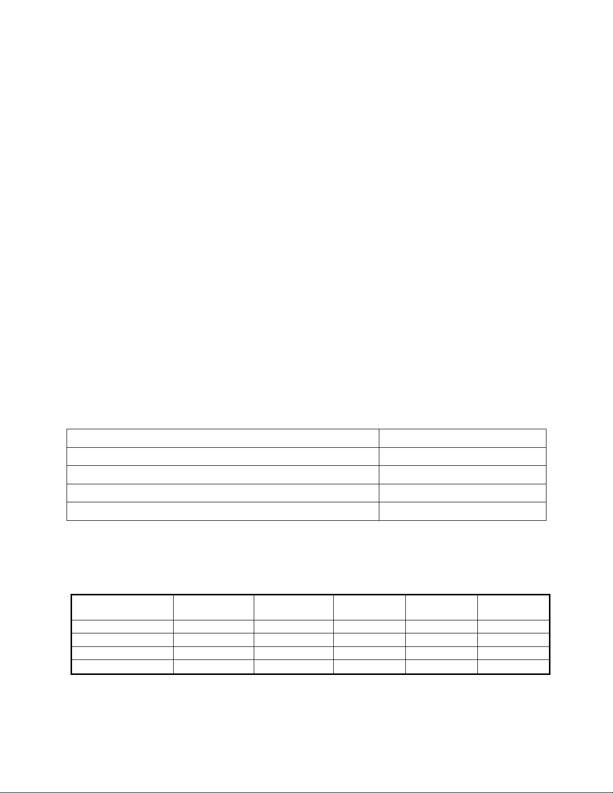
RELAY STATUS
LED COLOR
ON (FORCED ON FOR 5 MIN.)
AMBER
OFF
RED
AUTOMATIC ‘ON’
GREEN
AUTOMATIC ‘OFF’
OFF
Programmable
Inputs
Input 1
Input 2
Input 3
Input 4
Input 5
Drum Level
X ( Timer 1)
X (Timer 2)
X (Timer 3)
X (Timer 4)
X (Timer5)
Water meter
X X X X X
Hall effect
X
Flow
X
(866) 433-6682 • (281) 359-8538 • [email protected] • www.novatech-usa.com
1. INTRODUCTION
The MicroVision microprocessor based cooling tower controller has been designed to
control up to four (4) independent powered timer outputs. Each output can be
programmed in any one of the following modes, Pulse timer, Percent timer, 28 day
Biocide timer, or as a cycle timer. Relay number 5 may be programmed as an alarm
dry contact or as a fifth timer with a dry contact output.
The MicroVision has five (5) output relays assigned as follows:
Relay 1 – Timer #1
Relay 2 – Timer #2
Relay 3 – Timer #3
Relay 4 – Timer #4
Relay 5 – Alarm or Timer #5 (normally open dry contact)
2. MICROVISION FEATURES
2.1 Output Relays
The control of the four HANDS – OFF – AUTO (HOA) output relays can be controlled
using the HOA menu.
2.2 Inputs:
The MicroVision has 5 digital inputs that can be programmed as follows:
72-910-23 Rev.F
Page 4 of 30
Page 5
2.3 Drum Levels
(866) 433-6682 • (281) 359-8538 • [email protected] • www.novatech-usa.com
When an input is defined as a drum level it is linked to the corresponding relay
output. For example, if input #1 is set as drum level, it will be linked to relay one
and may be set by the user to either deactivate the relay, or only to activate an
alarm.
2.4 Flow Switch
MicroVision has a dry contact flow switch option for input number 5 only that will deactivate all of the control output relays upon a no-flow indication. An Alarm
condition will be indicated and “No Flow” will be displayed. This input is active closed:
Open = no flow; closed = flow.
If a flow switch input or other alarm condition exists, the four (4) LED’s will flash until
the alarm condition is cleared.
2.5 Water Meter
Each input may be programmed as water meter inputs that are capable of reading
a dry contact water meter. Input number one can be set to read a hall effect type
water meter. Through programming this input can be used to feed inhibitor as well as
totalizing water consumption.
2.6 Alarm Relay (Relay #5)
MicroVision has a dedicated dry contact relay that can be used to interface with
process control equipment or visual indicators. This relay is un-powered and may also
be programmed as a timer.
72-910-23 Rev.F
Page 5 of 30
Page 6
3. INSTALLATION
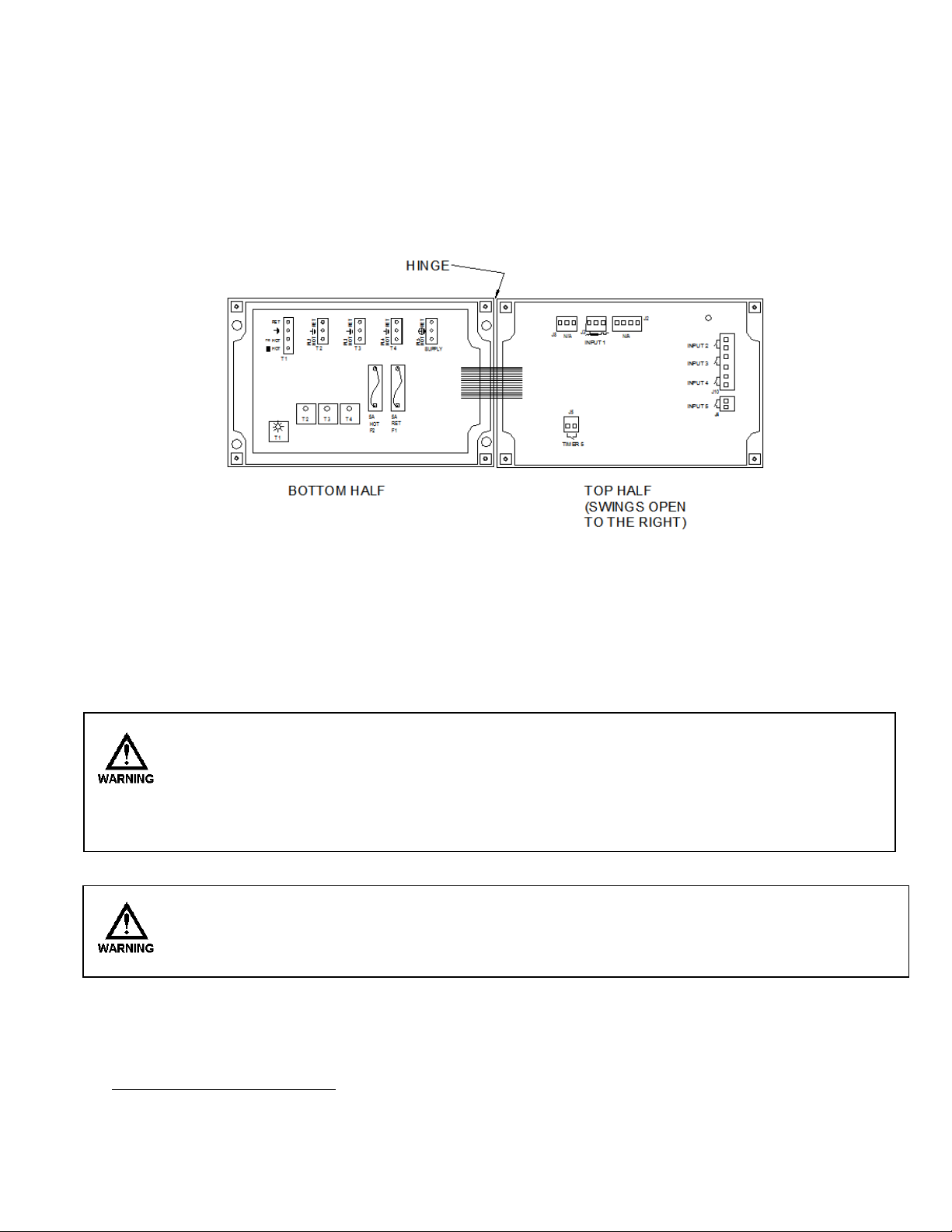
3.1 Opening The Enclosure1
Loosen the four (4) screws on the front of the controller and carefully swing the top of the
case to the right (Fig. 1).
Fig. 1
3.2 Location
Select a mounting location convenient to grounded electrical and plumbing connections. It
is recommended that you mount the controller on a wall or other vertical surface with
adequate lighting at a comfortable level. Installation should comply with all national, state,
and local codes.
AVOID LOCATIONS WHERE THE CONTROLLER WOULD BE SUBJECTED TO EXTREME COLD OR
HEAT {LESS THAN 0°F (-17,8°C) OR GREATER THAN 122°F (50°C)}, DIRECT SUNLIGHT,
VIBRATION, VAPORS, LIQUID SPILLS, OR EMI (ELECTROMAGNET INTERFERENCE; E.G., STRONG
RADIO TRANSMISSION AND ELECTRIC MOTORS.)
SAFETY PROTECTION PROVIDED BY THE EQUIPMENT MAY BE IMPARED IF THE
EQUIPMENT IS USED IN A MANNER NOT SPECIFIED BY THE MANUFACTURER. THIS CONTROLLER IS
INTENDED FOR INDOOR USE ONLY.
1
(866) 433-6682 • (281) 359-8538 • [email protected] • www.novatech-usa.com
Trained service personnel are required for all electrical connections. This product does not contain operator
serviceable parts.
72-910-23 Rev.F
Page 6 of 30
Page 7
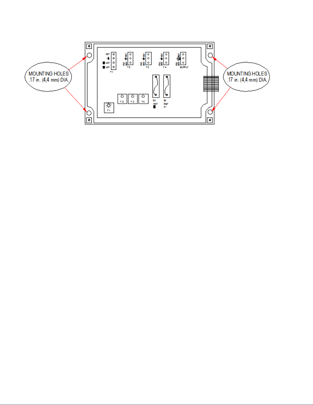
Fig. 2
Mount the bottom half of the controller using the four (4) holes provided (Fig. 2).
3.3 Mounting Hardware
For panel mounts without threaded inserts, four number 8 self taping screws are the minimum
recommendation.
For panel mounts with threaded inserts, four 8-32 screws are the minimum recommendation.
Panel mount hardware should support 25lbs. For hole locations, see the mounting hole
pattern (Fig. 9) found on the page 22 of manual.
3.4 Flow Sensor Switch
(866) 433-6682 • (281) 359-8538 • [email protected] • www.novatech-usa.com
If your controller is provided with a flow switch, install the flow switch so that flow
enters into the bottom of the flow switch tee, and out of the side of the tee. The flow
switch must always be installed in a vertical position so that the sensor wire is coming
out of the top, and the internal (red) flow shuttle is able to rise when there is flow and
drop when there is no flow. The flow switch is activated when 1 GPM (3,8 LPM) is
going through it, and is deactivated when the flow drops below 1 GPM (3,8 LPM).
72-910-23 Rev.F
Page 7 of 30
Page 8
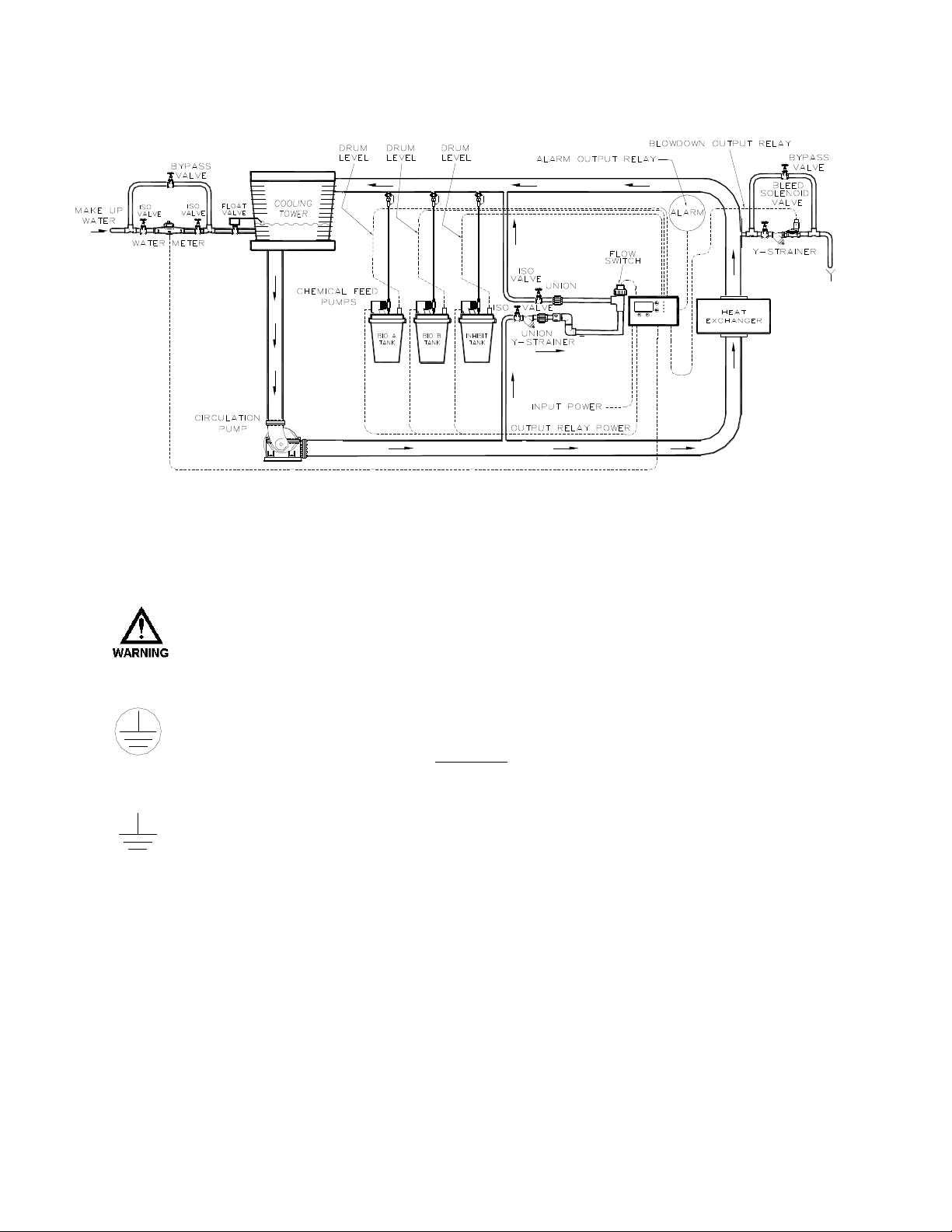
3.5 TYPICAL INSTALLATION
MicroVision
Timer 1
DISPLAY
SCREEN
TIMER
Timer 2
Timer 3
Timer 4
(866) 433-6682 • (281) 359-8538 • [email protected] • www.novatech-usa.com
Fig. 3
4. IMPORTANT SYMBOL INFORMATION
Warning indicates a condition that could cause damage to both
the equipment and the personnel operating it. Pay close attention
to any warning.
Primary Supply Ground must be connected to earth ground for safe
operation of your controller.
Chassis Ground – Connect your equipment’s ground wire here for
safe operation of your external devices.
72-910-23 Rev.F
Page 8 of 30
Page 9
5. ELECTRICAL WIRING2
Controller must be wired in accordance with all applicable electrical codes.
Input power must be 120 or 220VAC Single Phase.
Trained service personnel are required for all electrical connections. This
product does not contain operator serviceable parts.
Devices attached to any Relay connection must be Single Phase and rated for
the same voltage as the input voltage to the product. (e. g. 120VAC MicroTrac
controllers support 120VAC relay attached devices exclusively and 220VAC
MicroTrac controller support 220VAC relay attached devices exclusively.)
Input power cord must be disconnected from power source prior to opening the
product’s enclosure and making any electrical connections.
The controller should be connected to a dedicated power branch (i.e., its own
wiring, circuit breaker, etc.). For best results, the ground should be
independent (true earth) not shared.
A switch or circuit-breaker, marked as the unit’s disconnecting device should
be included in the installation. It should be in close proximity to the unit and
easily reached by the user.
2
(866) 433-6682 • (281) 359-8538 • [email protected] • www.novatech-usa.com
The MicroVision electronic input circuitry is fuse protected on both the hot and neutral inputs using
a replaceable five (5) amp fuse (Fig .6). For additional protection of your instrument, use of a surge
protector is recommended.
Pre-wired controllers are supplied with a 3-wire grounded power cord and 3-wire grounded
receptacle cords for all controlled line voltage outputs.
Trained service personnel are required for all electrical connections. This product does not contain operator
serviceable parts.
72-910-23 Rev.F
Page 9 of 30
Page 10
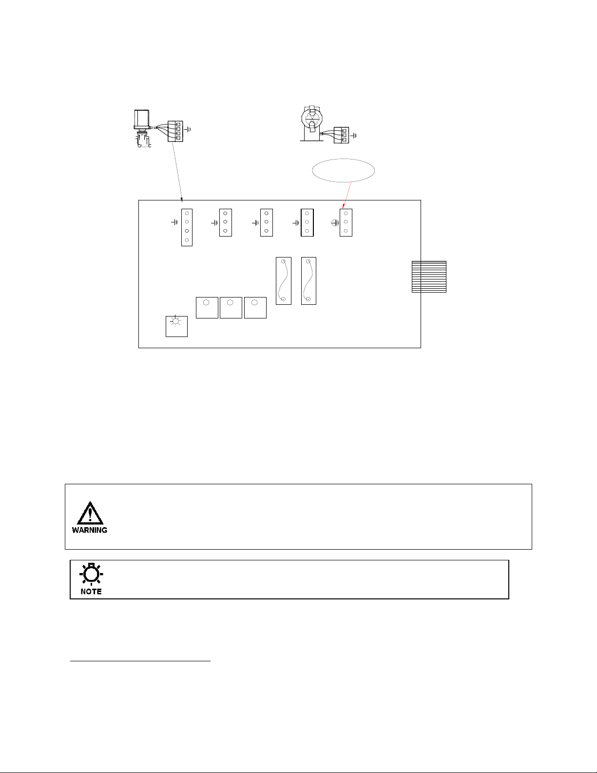
5.1 RELAY BOARD CONNECTIONS3
HOT
RET
HOT
RET
AC POWER IN
MOTORIZED BALL VALVE
(4-WIRE)
PUMP
(3-WIRE)
(RETURN / NEUTRAL)
(EARTH / CHASSIS GROUND)
(NORMALLY / OPEN)
(RETURN / NEUTRAL)
(EARTH / CHASSIS GROUND)
(NORMALLY / OPEN)
(NORMALLY / CLOSED)
T 1
T 2 T 3 T 4
SUPPLY
T 1
T 2 T 3
T 4
5AF25A
F1
HOT
RET
HOT
RET
HOT
RET
HOT
RET
HOT
RET
HOT
RET
PL2
PL3
PL4
PL5
HOT
no
nc
Devices attached to any Relay connection must be Single Phase and rated for
the same voltage as the input voltage to the product. (e. g. 120VAC MicroTrac
controllers support 120VAC relay attached devices exclusively and 220VAC
MicroTrac controller support 220VAC relay attached devices exclusively.) Do
not apply power until this condition is verified.
3
4
(866) 433-6682 • (281) 359-8538 • [email protected] • www.novatech-usa.com
Fig. 4
5.2 Conduit Models (Wiring High Voltage)4
Conduit controllers have openings for conduit connections for hard wiring. (See Fig.
4) for input and output power connections. Use only 18 AWG (1,2 mm²) stranded wire
for conduit power and load connections. Supply (input) power is connected via PL5
located on the relay board (Fig. 4). The top part of this terminal block is removable to
allow for easy access to the connector’s three (3) screws.
Make sure that all conduit connections are water tight.
Trained service personnel are required for all electrical connections. This product does not contain operator
serviceable parts.
Trained service personnel are required for all electrical connections. This product does not contain operator
serviceable parts.
72-910-23 Rev.F
Page 10 of 30
Page 11
The four (4) powered output relay terminal blocks are identified as: PL1 (Timer 1), PL2 (Timer 2),
J10
J4
J5
TIMER 5
RELAY (N.O.)
J3
J2
+5V
DRUM LEVEL
DETECTORS
CONTACT
METER
+5V
GND
J3
+5V
J3
OR
TOP
BOARD
WATER METER
TYPES
GND
INPUT 1
TIMER 5
FLOW
SWITCH
FLOAT
16-171-81-2 26" (,66m)
14-350-91
16-171-81-1 26" (1,17m)
16-171-81-4 26" (1,52m)
J8
INPUT 2
INPUT 3
INPUT 4
INPUT 5
CONTACT
METER
OR
OR
HALL
EFFECT
5
(866) 433-6682 • (281) 359-8538 • [email protected] • www.novatech-usa.com
PL3 (Timer 3), and PL4 (Timer 4). These terminal blocks can be removed in the same manner as
PL5. The Timer 1 relay has a N.O. and a N.C. connection, the others are only N.O. J5 is the alarm
dry contact (or timer 5) output relay.
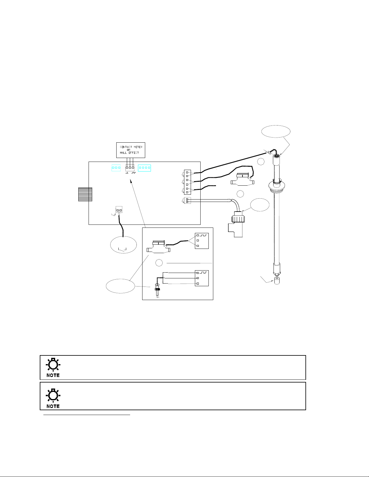
5.3 LOW VOLTAGE CONNECTIONS5
The low voltage connections are found on the low voltage (right side) board (Fig. 5).
Use 22-24 AWG (,76 mm²) wire for: flow switch, drum levels, dry alarm, and water
meter connections. These signal wires must be run separate from AC power lines.
Fig. 5
A Hall effect water meter can only be attached to J3 (Input #1).
Low voltage signal wires, e.g., a water meter, must be run separate from AC power lines.
These connections will be covered in the Low Voltage section of the manual.
Trained service personnel are required for all electrical connections. This product does not contain operator
serviceable parts.
72-910-23 Rev.F
Page 11 of 30
Page 12
(866) 433-6682 • (281) 359-8538 • [email protected] • www.novatech-usa.com
5.4 Inputs
5.4.1 Input # 1
Connect your water meter, or drum level switch to J3 of the top board. For proper
connections, refer to (Fig. 5) for your meter type, Hall effect, or contacting head may
be used.
5.4.2 Input # 2 to # 4
Connect your water meter, or drum level switch to J10 (Fig. 5). They are labeled as,
Input 2, 3, and 4. These are active closed: closed = low level; open = level is OK.
5.4.3 Input # 5
Connect your water meter, drum level switch, flow switch, or auxiliary dry contact
wires to J4
If you do not have a flow switch, a jumper wire must be connected across J4 if input
number 5 is programmed as flow.
5.5 Alarm Relay
Use J5 to connect your alarm reporting equipment. This relay will close when an
alarm condition exists and will open when no alarm conditions are present. See the
Trouble Shooting Guide (Page 21) for a description of alarm codes and their probable
causes.
72-910-23 Rev.F
Page 12 of 30
Page 13
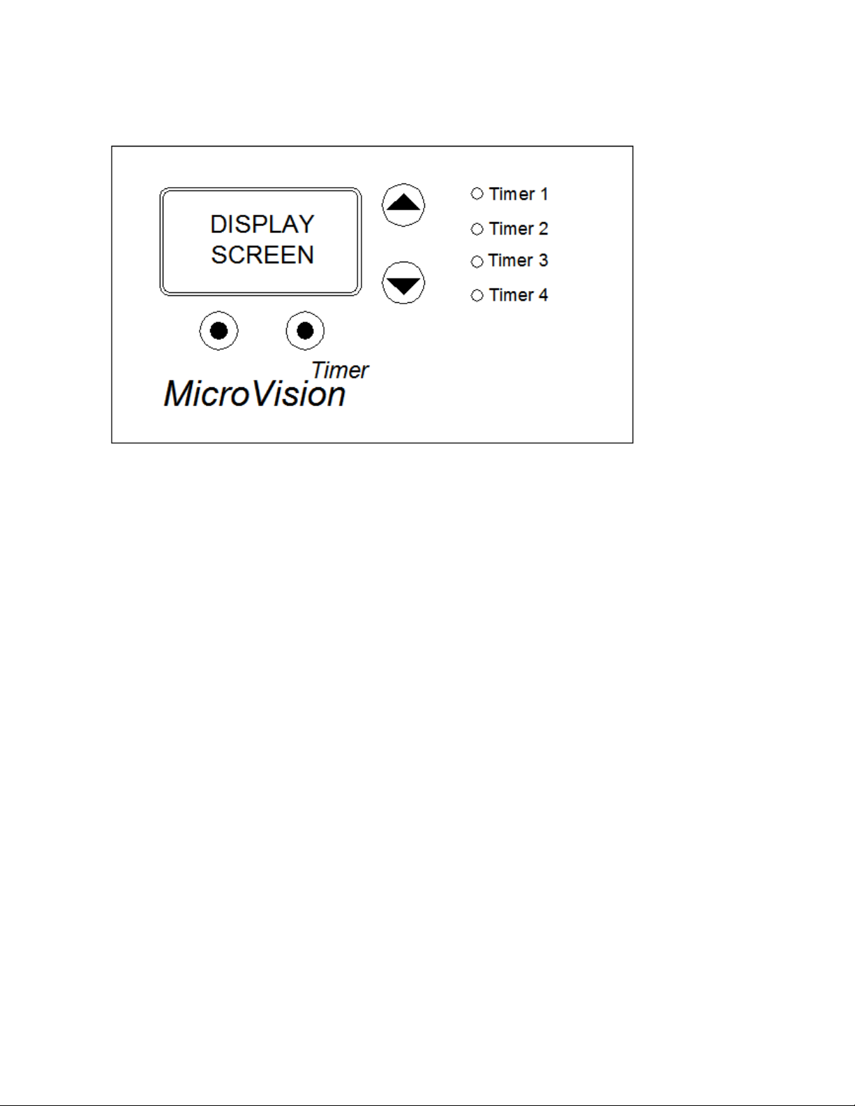
6. FRONT PANEL DESCRIPTION
(866) 433-6682 • (281) 359-8538 • [email protected] • www.novatech-usa.com
Fig. 6
6.1 Keypad Operation
UP/DOWN - Dual function keys. Used to move the select (highlighted) box and to
increase and decrease values.
O O - Soft keys used for various functions depending on currently displayed screen.
The key’s function appears above the key on the display.
72-910-23 Rev.F
Page 13 of 30
Page 14
7. CONTROLLER PROGRAMMING
CONFIGURE
ENTER
PASSWORD
DATE & TIME
HOA OUTPUTS
INPUTS
GAL/LIT
TOTALIZER
RISE/FALL
CONTRAST
PASSWORD
TROUBLESHOOT
SOFTWARE VER
FACTORY RST.
SETTINGS
TIMER 1 - 5
PULSE TIMER
28-DAY TIMER
CYCLE TIMER
DISABLED
PERCENT TIMER
HOME
SCREEN
STATUS MENU
SCROLLING
(866) 433-6682 • (281) 359-8538 • [email protected] • www.novatech-usa.com
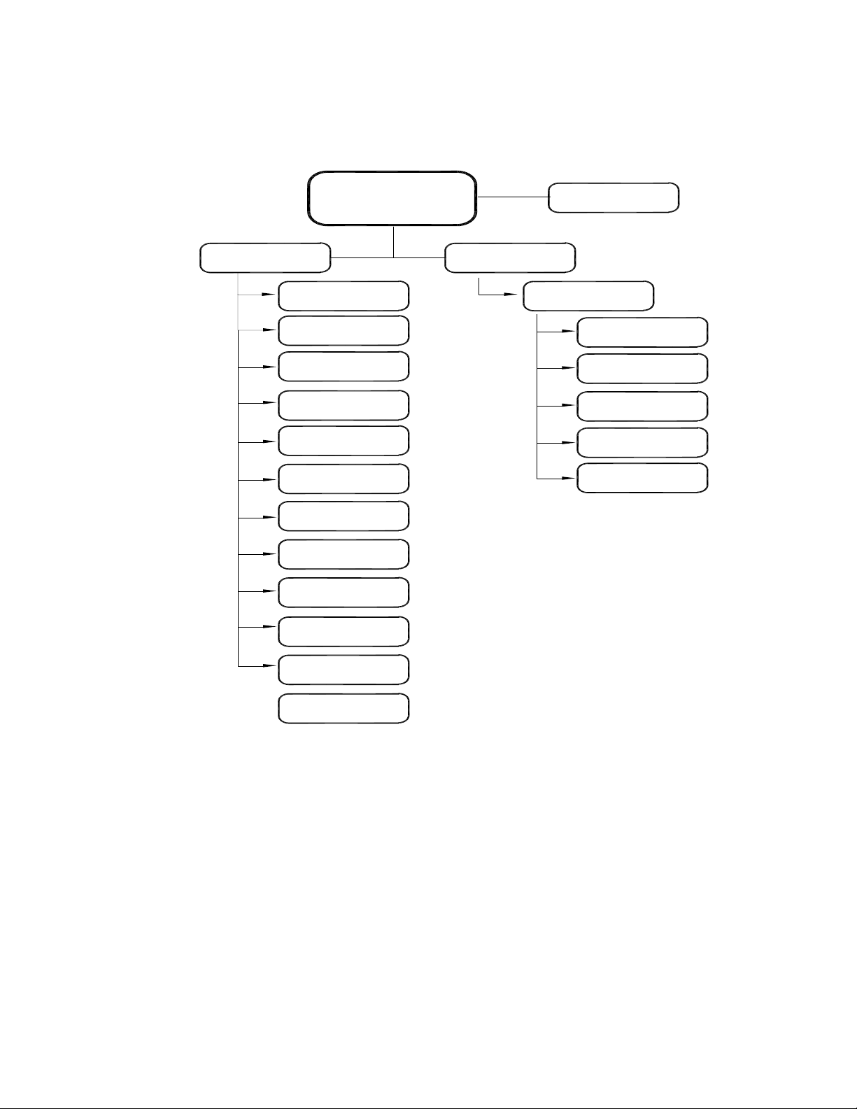
7.1 Menu Tree
7.2 Menu Navigation
MicroVision uses four front panel buttons to navigate through the different menus. Use these
buttons to move up and down within a list of options or move right and left to enter or change
parameter values. In some cases the Microvision display will prompt you to press the different
buttons to assist you in selecting or changing data.
Some menus may display highlighted menu options or a checkmark () next to a menu option.
The highlighted menu option is used to indicate that another menu will be displayed if this option
is chosen. The checkmark indicates that a particular control mode has been selected.
72-910-23 Rev.F
Page 14 of 30
Page 15
Home Screen
Output Hours
OP 1: 123.4 OP 2: 123.4
OP 3: 123.4 OP 4: 123.4
OP 5:
Last Error: Low Flow
Back | Reset
Home Screen
Configure
Settings
Back | Select
Date/Time
HOA Outputs
Inputs
Back | Select
Auto
On 5 Min
Off
01/23/07 | 11:42a
T1- Disabled
Status | Menu
(866) 433-6682 • (281) 359-8538 • [email protected] • www.novatech-usa.com
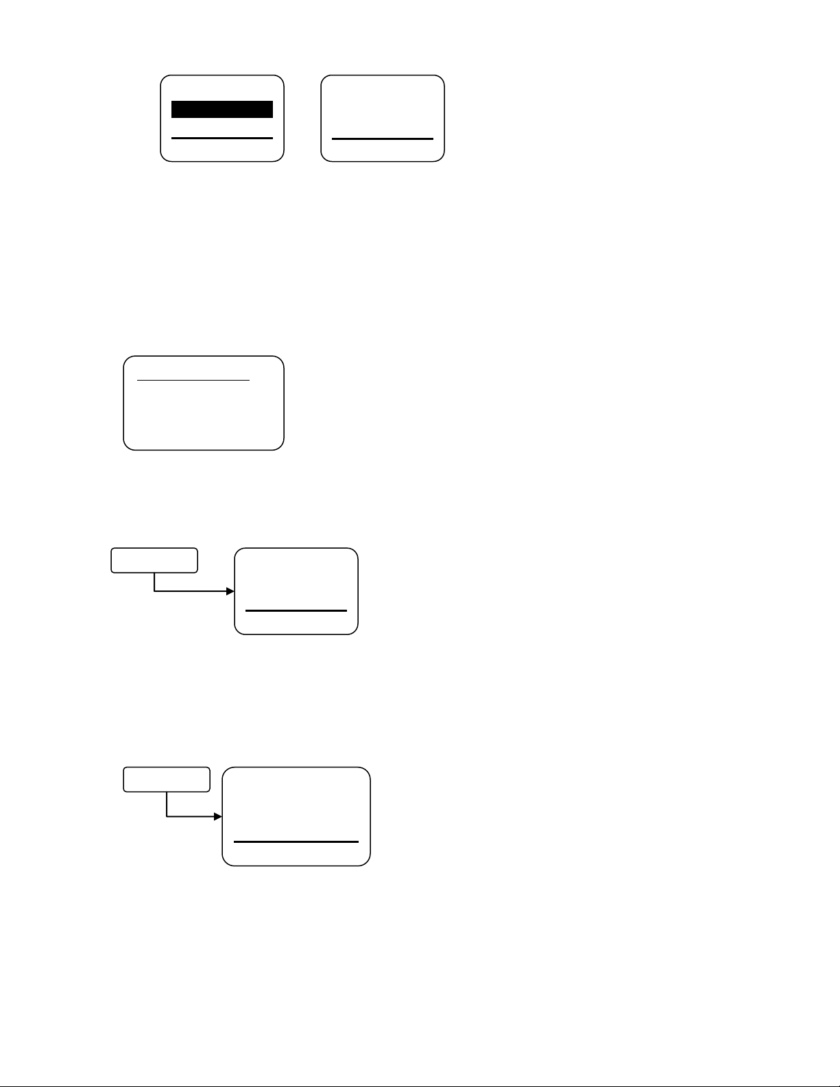
7.3 Home screen
This screen is displayed during normal operation when there are no alarm conditions on the
Microvision. If an alarm condition occurs an alarm message will flash on the screen. The four
LED’s to the right of the display will also flash indicating an alarm has occurred.
The Microvision will return to this screen if no buttons are pressed for five minutes after entering
a menu.
7.4 Main Menu
The Main menu is the starting point for all subsequent menus.
Configure – This menu allows you to set the time and date, display contrast, water
meter, etc.
Settings – This menu allows you to set the timer feed modes.
7.5 Status Screen
This screen shows the real-time data relating to the controller. This screen can be used
to log the amount of time a particular output was energized since it was last reset.
Below is a description of each of the data fields:
OP 1 – The amount of time, in hours, the Timer 1 output was energized since it was last
reset.
OP 2 – The amount of time, in hours, the Timer 2 output was energized since it was last
reset.
72-910-23 Rev.F
Page 15 of 30
Page 16
OP 3 – The amount of time, in hours, the Timer 3 output was energized since it was last
Home Screen
Date/Time
HOA Outputs
Inputs
Gal/Lit
Scrolling
Totalizers
Contrast
Password
Troubleshoot
Software Ver
Factory Rst
Back | Select
Configure
(866) 433-6682 • (281) 359-8538 • [email protected] • www.novatech-usa.com
reset.
OP 4 – The amount of time, in hours, the Timer 4 output was energized since it was last
reset.
OP 5 – The amount of time, in hours, that the dry contact relay 5 was energized since it
was last reset.
Last Error – Shows the most recent error that was displayed on the controller.
Pressing the reset key will cause the hour timers and water meter to reset to zero.
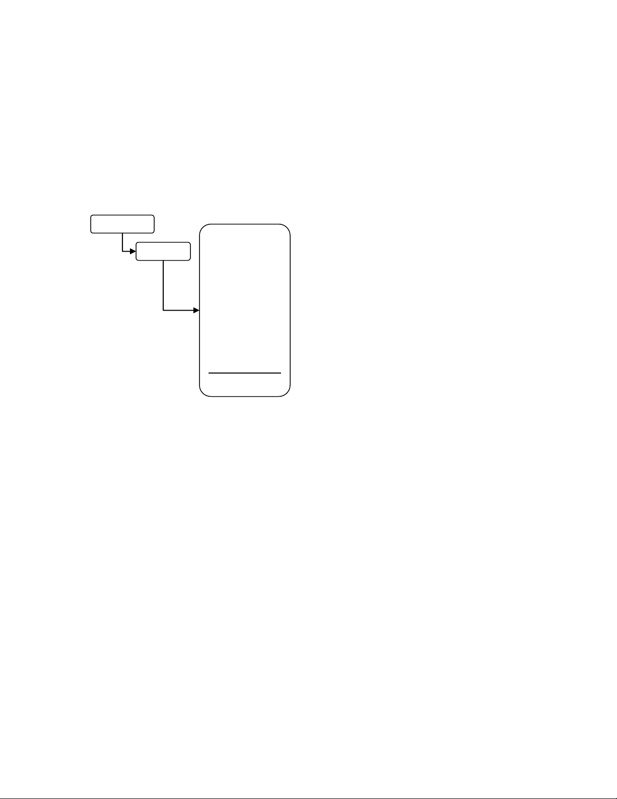
7.6 Configure Menu
From the Configure menu you can select many different system configuration options.
Date/Time – Set the current date, date format, time, and time format.
HOA Outputs – Manually control the five relays.
Inputs – Set the input type, drum level, or water meter type and volume.
Gal/Lit – Set the display in Gallons or liters.
Scrolling – Set the time between each timer’s status scrolling speed on the home
screen.
Totalizers- View the water meter totalizer values since the last user reset.
Contrast – Set the display contrast.
Password – Set the user password.
Troubleshoot – View the signal inputs in real-time to diagnose wiring problems.
Software Version – Displays the current software version.
72-910-23 Rev.F
Page 16 of 30
Factory Restore – Restore the parameters to factory default.
Page 17
7.7 Date/Time Menu
Home Screen
Configure
HOA Outputs
Timer 1
Timer 2
Timer 3
Timer 4
Timer 5
Back | Select
Auto
On 5 Min
Off
Back | Select
Home Screen
Configure
Date/Time
Set Date
Set Time
Date Format
Time Format
Back | Select
(866) 433-6682 • (281) 359-8538 • [email protected] • www.novatech-usa.com
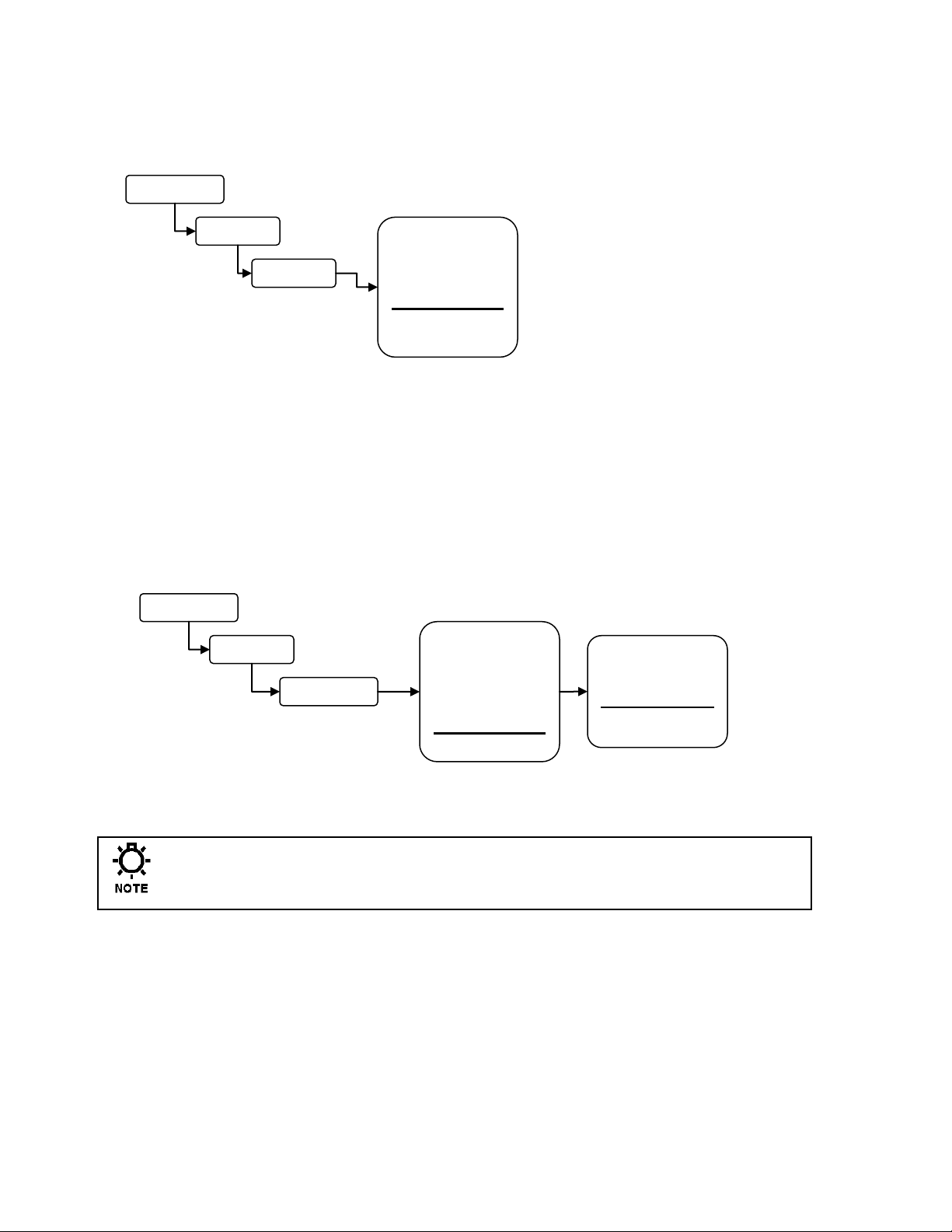
From the Date/Time menu you can set the date and time as well as the date and time display
formats.
Set Date – Set the current date.
Set Time – Set the current time.
Date Format – Pick the day/month/year format.
7.8 HOA Outputs Menu
From the HOA Outputs menu you can manually set the four relay control outputs. This is useful
for servicing chemical pumps or troubleshooting electrical problems. You must first select the
relay output to be controlled then select the relay state.
Time Format – Pick the 12-hour or 24-hour time of day format.
Auto – Return the control output to normal operation.
On 5 Min – Energize the control output for five minutes.
Off – De-energize the control output indefinitely.
Forcing the output to Auto may cause the control output to energize without warning.
72-910-23 Rev.F
Page 17 of 30
Page 18
7.9 Inputs Menu
Home Screen
Configure
Input 1
Dry Contact
Hall Effect
√Drum low
Back | Select
Pump Stops
Pump Runs
Back | Select
Home Screen
Configure
Inputs
Input 1
Input 2
Input 3
Input 4
Input 5
Back | Select
Input 1
Dry Contact
Hall Effect
Drum low
Back | Select
Input 2 -4
Dry Contact
Drum low
Back | Select
Input 5
Dry Contact
Flow Switch
Drum low
(866) 433-6682 • (281) 359-8538 • [email protected] • www.novatech-usa.com
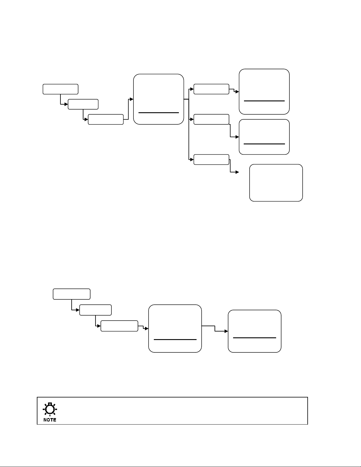
From the Inputs menu you select what type of device the controller is attached to. Once the type
of input has been entered the next screen will ask you for the gallons/liters per pulse or “K-
factor”, or level action depending on the type of device.
Input Type – Select between a dry contact or Hall-effect water meter, or drum level on
input 1. Select between a dry contact water meter, or drum levels on input 2 to 4. Select
between a dry contact water meter, or drum level or flow switch on input 5. Once the
type is selected as a water meter the resolution or volume per pulse is then set.
7.10 Drum Levels Sub Menu
From the Drum Level menu you select how you want the chemical pump control output to
respond to a low drum level indication. Your choices are to allow the pump to continue to run or
have the pump stop when its drum level goes low. Input one is tied to relay one
Pump Stops – Selecting this mode causes the timer outputs to de-energize when their
drum level goes low.
Pump Runs – Selecting this mode causes the timer outputs to remain energized even
though their drum level has gone low.
When a drum level goes low the controller will go into alarm regardless of this setting.
Re-filling a low drum may cause the pump control output to energize without warning.
72-910-23 Rev.F
Page 18 of 30
Page 19
7.11 Display Contrast Setting
Home Screen
Configure
Totalizers
Water Mtr #1: 000000000
Water Mtr #2: 000000000
Water Mtr #3: 000000000
Water Mtr #4: 000000000
Water Mtr #5: 000000000
Cancel |Reset
Home Screen
Configure
Scrolling
Scrolling
03 Sec
Cancel |Enter
Home Screen
Configure
Gal/Lit
√Gallons
Liters
Cancel |Enter
Contrast
Contrast
26
Cancel |Enter
Configure
Home Screen
(866) 433-6682 • (281) 359-8538 • [email protected] • www.novatech-usa.com
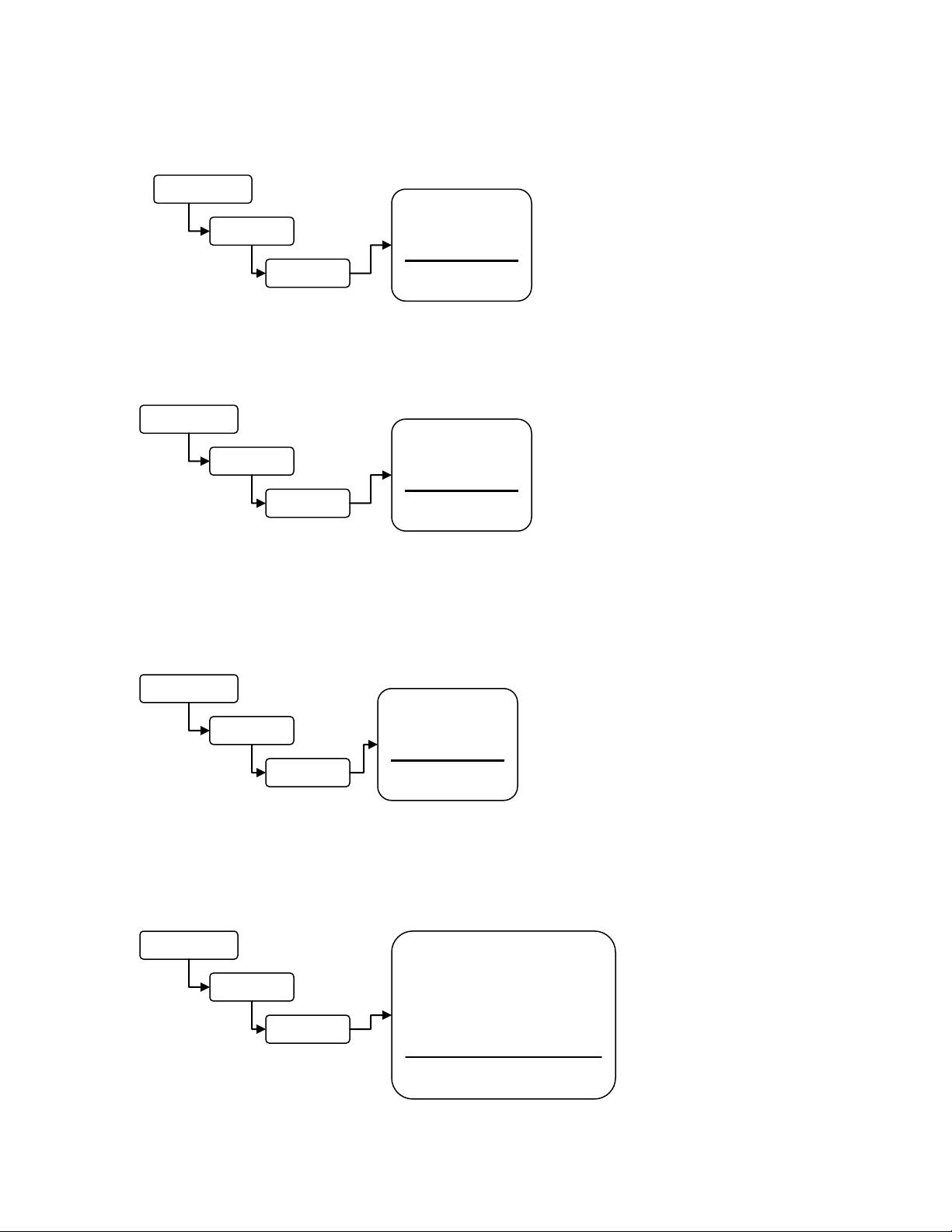
From the Display Contrast setting you adjust the display contrast to give the best clarity and
readability of the display screen.
Contrast – Adjust this value up or down to give you the best display contrast.
7.12 Gallons or Liters
Gal/lit – Set how the controller should display the water meter units of measure.
7.13 Scrolling
From the Display Scrolling setting you can adjust how frequently the controllers display will
scroll from one timer’s status to the next timer on the home screen.
Scrolling – Set the number of seconds to scroll.
7.14 Totalizers
From the Totalizers screen you can view the totalized values of each of the five possible water
meter inputs and reset them if desired.
72-910-23 Rev.F
Page 19 of 30
Reset – Sets the totalizers back to zero.
Page 20
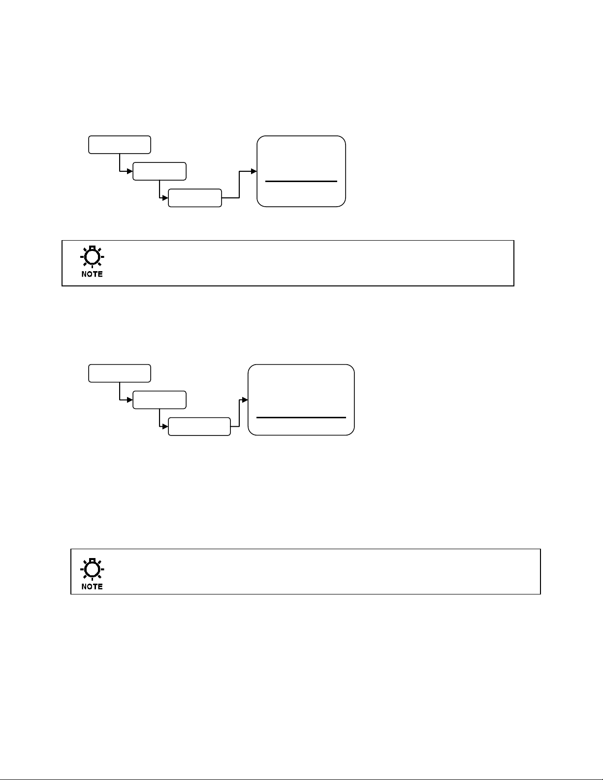
7.15 Password Setting
Home Screen
Configure
Troubleshoot
Ip 1: Open Ip 2: Open
Ip 3: Open Ip 4: Open
Ip 5: Open
Wk: 2 Day:Mon Sec:23
Back | Back
Home Screen
Configure
Password
Change
Password
0000
Cancel |Enter
(866) 433-6682 • (281) 359-8538 • [email protected] • www.novatech-usa.com
From the Password setting you select the user password that will be required to gain access to
the Configuration and Settings menus. Once the password is set to anything other than 0000 (4zeros) the password feature is enabled. To disable password protection return the password to
0000 (4-zeros).
Password – Set the user password.
Once the password is set the controller will require a password to access any menus. If the
password is lost or unknown you will have to call technical service to gain access to the
controller menus. Please have the controller in front of you when you place the call.
8. Troubleshoot Screen
From the Troubleshot Screen you can view the Microvision control inputs in real-time. This is a
great tool for checking the correct operation of sensors that are attached to the controller.
Flow input – Water flow switch input (J4 pins 1-2).Flow=closed, No flow = open.
Drum Levels – Inhibitor drum level input Empty=closed, OK=open.
Water Meter – Water meter input (J3 pins 1-3). Open=contact open, closed=contact
closed.
Wk – Revolving week number between one and four. This is used in the biocide
Days/Weeks settings.
Day – Day of week. This is used in the biocide Days/Weeks settings.
Sec - Current clock seconds.
While this screen is displaying information the controller is still functioning normally and relay
outputs may energize without warning due to changing signal inputs.
72-910-23 Rev.F
Page 20 of 30
Page 21
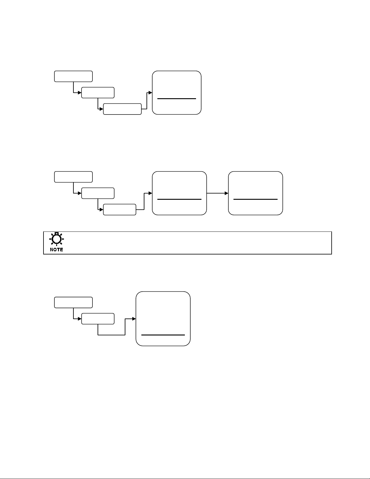
9. Software Version
Home Screen
Timer 1
Timer 2
Timer 3
Timer 4
Timer 5
Back | Select
Settings
Home Screen
Configure
Factory Rst
Factory Reset
Are you sure!
Cancel | OK
To RESET
Enter 9999
0000
Cancel | OK
Home Screen
Configure
Software Ver
Software
Version
01.00
Back |Back
(866) 433-6682 • (281) 359-8538 • [email protected] • www.novatech-usa.com
From the Software Version screen you can view the current software that is running in the
Microvision controller.
10. Factory Reset Function
From the Factory Reset Function screen you can force the controller to reset all of its internal
parameter to the factory default values.
Use this function to reset the controller back to the factory defaults.
Be absolutely certain you want to reset all the parameters back to the factory defaults. Once the
reset takes place there is no way to retrieve the previous parameters.
11. Settings Menu
From the Settings menu you access the timer mode and parameter sections.
72-910-23 Rev.F
Page 21 of 30
Page 22
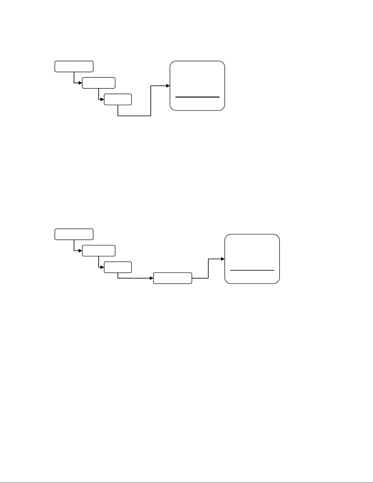
11.1 Timer Mode Menus
Home Screen
Settings
Timer 1
Feed Time
Accum Set
Accum Count
Water Meter
Back | Select
√Pulse Timer
Home Screen
Settings
Timer 1
Pulse Timer
Percent Timer
28 Day Tmr
Cycle Timer
Back | Select
(866) 433-6682 • (281) 359-8538 • [email protected] • www.novatech-usa.com
From this menu pick the mode that the inhibitor feed will follow.
Pulse Timer – See the menu for this function in the following section.
Percent Timer – Set the timer run time period and percentage of the time period.
Example: Cycle Time=60minutes, % Minutes to run=10, the timer will run for 10% of 60
minutes, or 6 minutes every 60 minutes.
28 Day Timer (Biocide) – See the menu for this function in the following section.
Cycle Timer - See the menu for this function in the following section.
11.2 Timer Modes – Pulse Timer Menu
From this menu configure how you want the inhibitor to feed while in pulse timer mode. This
mode uses the water meter input to cause a counter to accumulate a certain volume of water
before the inhibitor is feed. Once the accumulated volume is reached the inhibitor is feed for the
programmed Feed Time.
Feed Time – Set this value to the amount of time you want the timer to run for when the
water meter accumulator reaches its target.
Accumulator Set – Set this value to the amount of water that needs to accumulate prior
to a timer run time. The units will be in gallons or liters depending on what you set the
water meter units to.
Accumulator Count – This is the current running count of the water meter accumulator.
Water meter – Select which of the five possible water meter inputs will activate the
pulse timer.
72-910-23 Rev.F
Page 22 of 30
Page 23
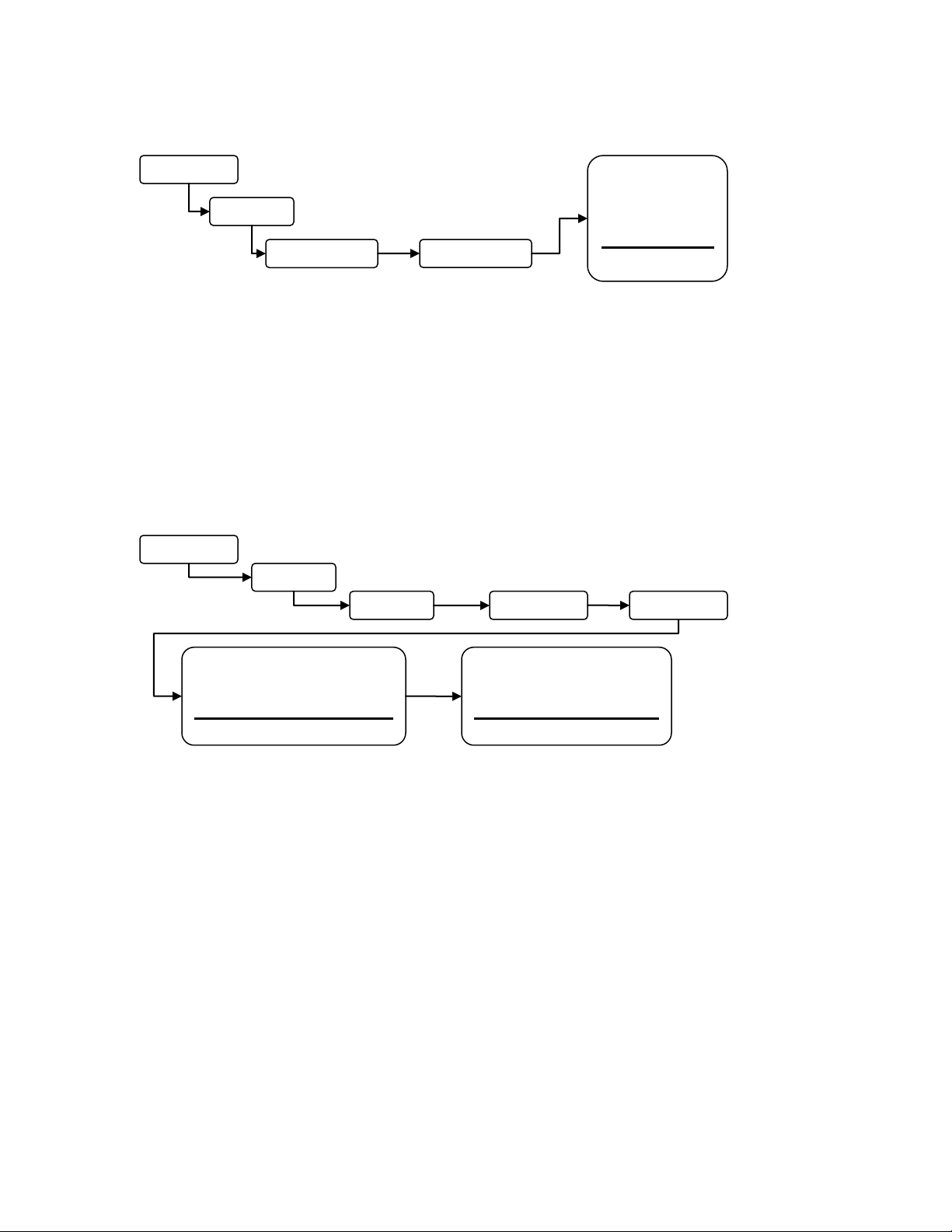
11.3 28 Day Menu
Home Screen
Settings
Timer 1
ALL | SUN| MON| TUE
WED| THU| FRI | SAT
Days On|Off
Cancel | Enter
Days/Weeks
ALL | EVN| ODD| 1ST
2ND | 3RD| 4TH |
Weeks On|Off Wk#2
Cancel | Enter
28 Day Tmr
Home Screen
Settings
Timer 1
Days/Weeks
Start Times
Feed Time
Back | Select
28 Day Tmr
(866) 433-6682 • (281) 359-8538 • [email protected] • www.novatech-usa.com
From this menu configure how often and the duration you want the timer to run.
Days/Weeks – Set the days and weeks you want the timer to run for. See the next
section for details on how to set the days and weeks.
Start Times – Set up to four start times. Setting the value to 00:00 means the start time
is ignored.
Feed Time – Set this value to the amount of time you want the timer to run for each time
a cycle is started.
11.4 28 Day Menu – Days/Weeks Menu
From this menu configure the days and weeks the timer will activate. Any combination of days
and/or weeks is acceptable for each timer.
- Select the timer start days and weeks by using the up and down buttons to the right of
the display. Move the cursor to the right or left by using the button to the bottom of the
display. The selected day or week will flash as the cursor is moved to each setting. The
flashing On|Off text indicates if the current setting is on or off.
- If a day or week is highlighted, or appears as reverse video, that particular day or week
will activate the timer.
- The week # shown in the lower right of the display indicates which week number the
controller’s time is currently set to.
72-910-23 Rev.F
Page 23 of 30
Page 24
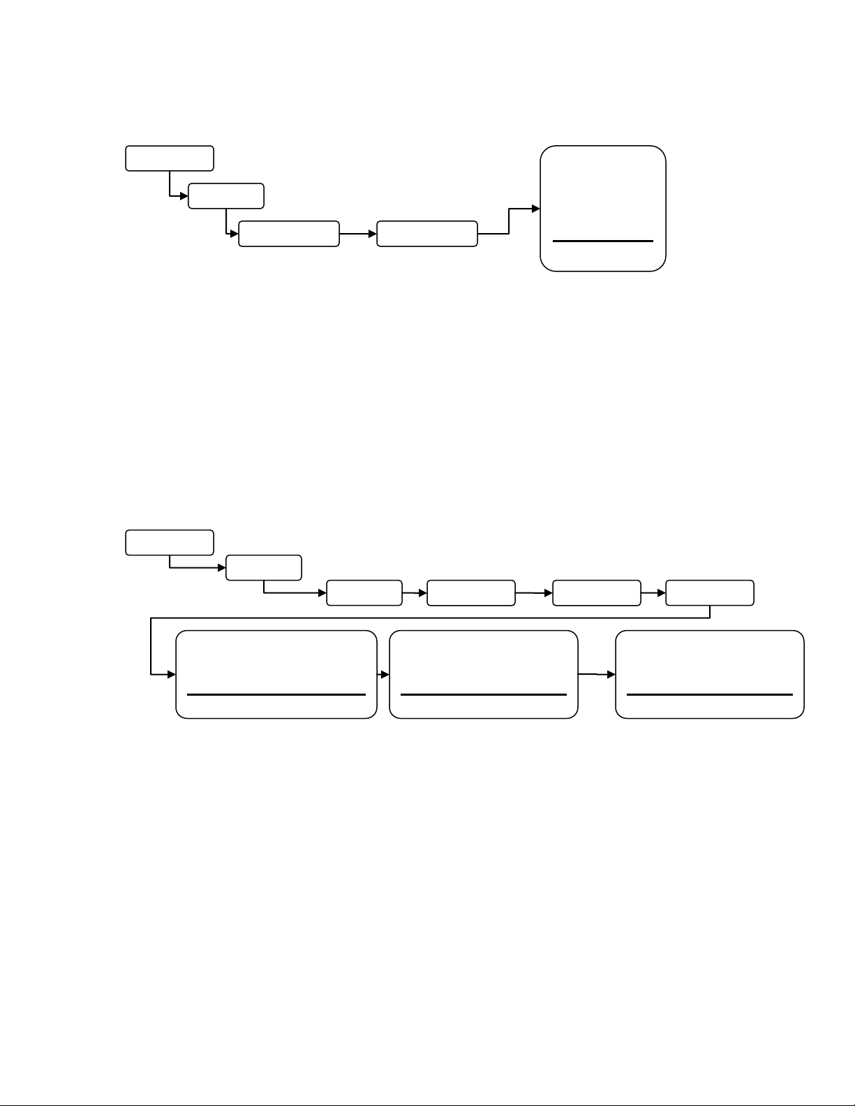
11.5 Cycle Timer Menu
Home Screen
Settings
Timer 1
ALL | SUN| MON| TUE
WED| THU| FRI | SAT
Days On|Off
Cancel | Enter
Start times
ALL | EVN| ODD| 1ST
2ND | 3RD| 4TH |
Weeks On|Off Wk#2
Cancel | Enter
Cycle Timer
Start Time 1
hh:mm
01:00A
Cancel | Enter
Start time 1
Home Screen
Settings
Timer 1
On Time
Off Time
# Cycles
Start Times
Back | Select
Cycle Timer
(866) 433-6682 • (281) 359-8538 • [email protected] • www.novatech-usa.com
From this menu configure how often and the duration you want the timer to run for. The cycle
timer is very similar to the 28 day timer
On Time – Sets the duration that the timer will activate the output for.
Off Time – Sets the duration that the timer will deactivate the output for.
# Cycles - Set the number of times the timer will repeat the on and off times at the start
time setting described below.
Start Times – Set up to four start times. Setting the value to 00:00 means the start time
is ignored. Set the days and weeks you want the timer to run for. See the next section
for details on how to set the days and weeks.
11.6 Cycle Timer Menu – Start Times
From this menu configure the days and weeks the timer will run for. Any combination of days
and/or weeks is acceptable for each timer.
- Select the timer start days and weeks by using the up and down buttons to the right of
the display. Move the cursor to the right or left by using the button to the bottom of the
display. The selected day or week will flash as the cursor is moved to each setting. The
flashing On|Off text indicates if the current setting is on or off.
- If a day or week is highlighted, or appears as reverse video, that particular day or week
will have biocide feed.
- The week # shown in the lower right of the display indicates which week number the
controller’s time is currently set to.
72-910-23 Rev.F
Page 24 of 30
Page 25
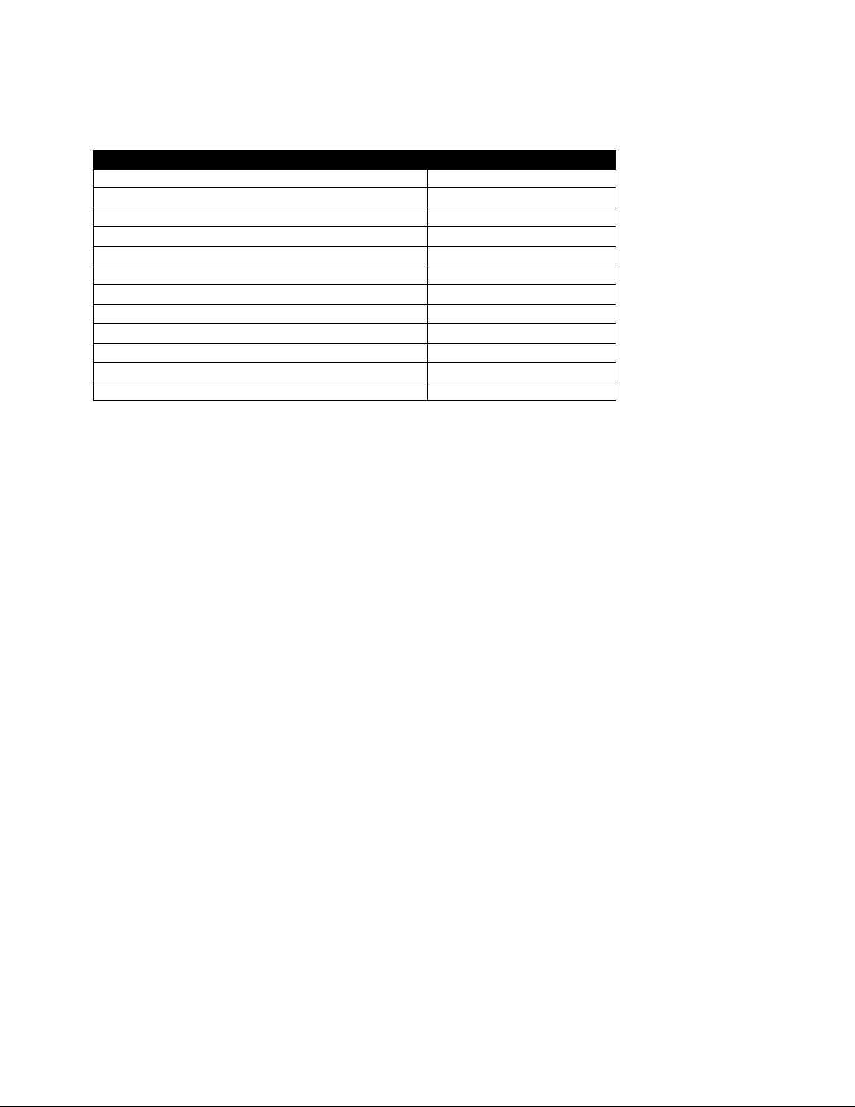
12. Factory Defaults
Parameter
Default
Configuration
Date Format
MM/DD/YY
Time Format
12hr Clock
Inputs
Dry Contact
Water Meter Pulse Volume
100
Units
Gallons
Drum Levels
Pumps Run
Scrolling
3 Seconds
Display Contrast
26
Password
0000(disabled)
Settings
Timer Modes
Disabled
(866) 433-6682 • (281) 359-8538 • [email protected] • www.novatech-usa.com
72-910-23 Rev.F
Page 25 of 30
Page 26
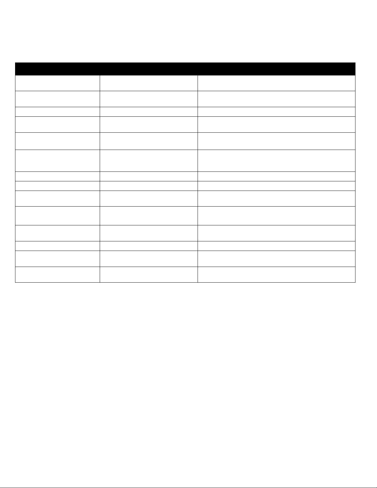
13. TROUBLESHOOTING GUIDE
Symptom
Probable Cause
Possible Solution
Controller does not power
up.
No power supplied to controller.
Insure that correct voltage is supplied to controller.
Check circuit breaker supplying power to the
controller.
Fuse is blown.
check/replace fuses F1-F3 (see Figure 2, Page 5)
Ribbon cable.
Check ribbon cable connecting upper and lower pc
boards inside controller.
Controller displays “No
Flow” alarm message.
No flow thru flow assembly.
Insure there is enough water flow through the
assembly. At least 1 GPM (3.8 LPM) of flow.
Flow switch wiring or connector
loose.
Check flow switch connections (see Figure 5, Page 8).
Flow switch stuck.
Clean flow switch sensor mechanicals.
Flow assembly clogged.
Clean inside flow assembly.
Flow switch input jumper
missing.
Install jumper if flow switch is not used.
Controller displays "Drum
X Low" alarm message.
Drum fluid level low.
Refill drum for timer X. (where x =1 to 5)
Drum level switch wiring or
connector loose.
Check switch connections (See Figure 5, Page 8).
Drum level switch stuck.
Clean switch sensor mechanicals.
Controller displays "Clock
Err" alarm message.
Internal controller clock failure.
Replace controller.
Controller displays
"Watchdog" alarm message.
Internal controller failure.
Replace controller.
(866) 433-6682 • (281) 359-8538 • [email protected] • www.novatech-usa.com
72-910-23 Rev.F
Page 26 of 30
Page 27
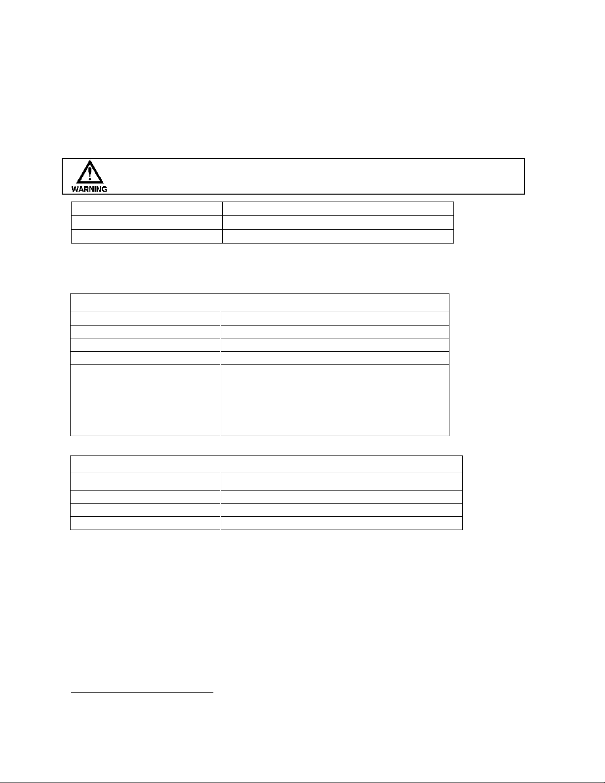
14. MAINTENANCE
FUSE6
TYPE
F1 & F2
5A, IEC 60127-2 · 250 VAC · Time-Lag T
F37
1A, 2AG, Time Lag, 250VAC
Controller
Enclosure
NEMA 4X/ Designed to meet IP65
Enclosure Dimensions
6.4" x 3.2" x 3.2" (163 x 82 x 82mm)
Power supply
120 or 220 VAC; 50/60Hz.
Display
LCD 0 - 9,999 µS/cm range 1µS/cm resolution
Maximum relay output current
120 VAC:
5 A Resistive/General use
4LRA/4FLA,1/10HP (motors)
220 VAC:
5 A Resistive/General use
Not rated for motors
Flow Switch
Maximum temperature
127°F (52°C)
Maximum pressure
125 PSI (8,6 BAR)
Activate flow rate
Approximately 1 GPM (3,785 LPM)
Materials of construction
PVC and Glass filled Polypropylene
6
7
(866) 433-6682 • (281) 359-8538 • [email protected] • www.novatech-usa.com
There are no regular maintenance requirements. All other service should be
performed by factory authorized personnel only. Modifications to or tampering with
the circuit level components makes all warranties, written or implied, and/or
manufacturer’s responsibility for this controller, null and void.
DISCONNECT POWER BEFORE OPENING THE UNIT TO ACCESS FUSES. MAKE SURE
THAT REPLACEMENT FUSES ARE OF SAME TYPE TO MAINTAIN SAFTEY APPROVALS.
15. SPECIFICATIONS
All fuses are UL, CSA recognized or listed.
F3 is not serviceable in the field.
72-910-23 Rev.F
Page 27 of 30
Page 28
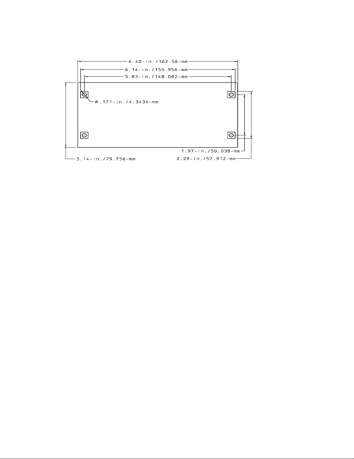
16. MOUNTING HOLE PATTERN (Footprint)
(866) 433-6682 • (281) 359-8538 • [email protected] • www.novatech-usa.com
Fig. 7
72-910-23 Rev.F
Page 28 of 30
Page 29

17. Factory Service Policy
(866) 433-6682 • (281) 359-8538 • [email protected] • www.novatech-usa.com
Your MICROVISION is a state of the art microprocessor based controller. If you are
experiencing a problem with your process control instrument, first consult the troubleshooting
guide in this manual. If the problem is not covered or cannot be solved, contact Technical
Services for assistance:
PULSAFEEDER INC. (SPO)
27101 AIRPORT ROAD
PUNTA GORDA, FL 33982
941-575-3800
Trained technicians are available to diagnose your problem and arrange a solution.
Solutions may include purchase of replacement parts or returning the controller to the
factory for inspection and repair. All returns require a Return Authorization number to be
issued by Pulsafeeder. Parts purchased to correct a warranty issue may be credited after an
examination of original parts by Pulsafeeder. Warranty parts returned as defective which
test good will be sent back freight collect. No credit will be issued on any replacement
electronic parts.
Any modifications or out-of-warranty repairs will be subject to bench fees and costs
associated with replacement parts.
18. Warranty
Pulsafeeder, Inc. warrants control systems of its manufacture to be free of defects in material
or workmanship. Liability under this policy extends for 24 months from date of shipment.
Electrodes/probes are considered maintenance items and as such are warranted for six (6)
months from the date of shipment of the controller. Electrodes/probes purchased as spare
parts are warranted for 24 months from date of shipment. The manufacturer's liability is
limited to repair or replacement of any failed equipment or part, which is proven defective
in material or workmanship upon completion of the manufacturer's examination. This
warranty does not include removal or installation costs and in no event shall the
manufacturer's liability exceed the selling price of such equipment or part.
The manufacturer disclaims all liability for damage to its products through improper
installation, maintenance, use, or attempts to operate such products beyond their functional
capacity, intentionally or otherwise, or any unauthorized repair. The manufacturer is not
responsible for consequential or other damages, injuries, or expense incurred through the use
of its products.
The above warranty is in lieu of any other warranty, whether expressed or implied. The
manufacturer makes no warranty of fitness or merchantability. No agent of ours is authorized
to provide any warranty other than the above.
72-910-23 Rev.F
Page 29 of 30
Page 30

USA
sales@novatech-usa.com
www.novatech-usa.com
Tel: (866) 433-6682 Fax: (866) 433-6684
Tel: (281) 359-8538 Fax: (281) 359-0084
European Union (EU)
Pulsafeeder, Inc.
27101 Airport Rd.
Punta Gorda, FL 33982
USA
(941) 575-3800
www.pulsa.com
PULSAFEEDER-Europe
Via Kennedy, 12-20090
Segrate—Milano– Italy
72-910-23 Rev.F
Page 30 of 30
 Loading...