

Page 1
f
r
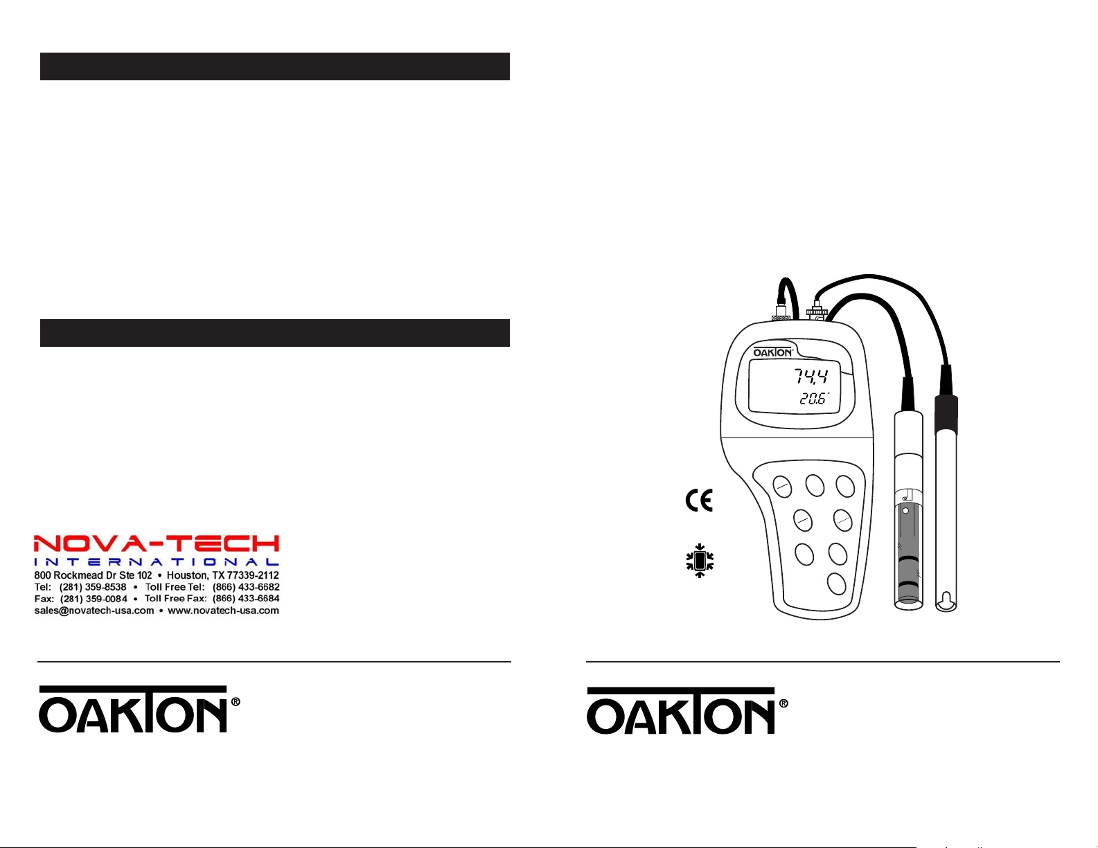
pH/Conductivity/°C/°F Meter
pH/CON 300 Series
WATERPROOF
MODE
HOLD
ENTER
RANGE
ON
OFF
CAL
MEAS
▲
▼
SETUP
ATC
READY
MEAS
C
µS
I
P
67
16. Warranty
OPERATING INSTRUCTIONS
OAKTON warrants this meter to be free from significant deviations in material
and workmanship for a period of three years from date of purchase. OAKTON
warrants this probe to be free from significant deviations in material and
workmanship for a period of six months from date of purchase. If repair or
adjustment is necessary and has not been the result of abuse or misuse within
the warrantied time period, please return—freight prepaid—and correction will
be made without charge. OAKTON alone will determine if the product problem
is due to deviations or customer misuse.
Out-of-warranty products will be repaired on a charge basis.
17. Return of items
Authorization must be obtained from our Customer Service Department before
returning items for any reason. When applying for authorization, please include
data regarding the reason the items are to be returned. For your protection, items
must be carefully packed to prevent damage in shipment and insured against possible damage or loss. We will not be responsible for damage resulting from careless or
insufficient packing. Arestocking charge will be made on all unauthorized returns.
NOTE: We reserve the right to make improvements in design, construction, and
appearance of products without notice.
OAKTON®35631-00
Portable Waterproo
pH/CON 300 Mete
00702-89
R1 Printed in the U.S.A. 10/00
Page 2

Table of Contents
1. Introduction ............................................................................................4
2. Display and keypad functions .............................................................5-6
2.1 Display...................................................................................................................................5
2.2 Keypad...................................................................................................................................6
3. Preparation..........................................................................................7-9
3.1 Inserting the batteries..........................................................................................................7
3.2 Probe information.............................................................................................................8-9
4. Calibration.......................................................................................10-16
4.1 Important information on meter calibration .................................................................10
4.2 Preparing the meter for calibration .................................................................................10
4.3 pH calibration................................................................................................................11-12
4.4 Conductivity and TDS calibration .............................................................................13-15
4.5 Temperature calibration....................................................................................................16
5. Measurement...................................................................................17-22
5.1 Taking pH measurements .................................................................................................17
5.2 Taking conductivity or TDS measurements...................................................................18
5.3 HOLD function / Ready indicator / Auto endpoint...................................................19
5.4 Using manual ranging function: conductivity/TDS....................................................20
5.5 Selecting manual temperature compensation: conductivity/TDS.............................21
5.6 Selecting the manual temperature compensation value..............................................22
ogram 4.0: Resetting to factory default settings (pH) ...............................................31
6.5 Pr
ogram 5.0: Viewing previous conductivity/TDS calibration data..........................32
6.6 Pr
ogram 6.0: Viewing conductivity/TDS probe data (effective cell constant) .........33
6.7 Pr
ogram 7.0: Conductivity/TDS measurement configuration ..............................34-37
6.8 Pr
P7.1 Selecting Ready indicator/auto endpoint function.............................................34
P7.2 Selecting °C or °F......................................................................................................35
P7.3 Selecting automatic or manual temperature compensation...............................36
P7.4 Setting the TDS factor ..............................................................................................37
ogram 8.0: Temperature settings.............................................................................38-39
6.9 Pr
P8.1 Setting the temperature coefficient........................................................................38
P8.2 Selecting the normalization temperature ..............................................................39
ogram 9.0: Resetting to factory default settings (conductivity/TDS)..................40
6.10 Pr
7. Probe care and maintenance...........................................................41-42
7.1 pH electrode care..........................................................................................................40-41
7.2 Conductivity probe care....................................................................................................41
8. Troubleshooting....................................................................................43
9. Error Messages......................................................................................44
10. Specifications......................................................................................45
11. Accessories.....................................................................................46-47
6. Advanced setup functions...............................................................23-40
6.1 Advanced setup mode overview................................................................................24-25
pH .......................................................................................................................................24
Conductivity/TDS ............................................................................................................25
ogram 1.0: Viewing previous pH calibration data....................................................26
6.2 Pr
ogram 2.0: Viewing pH electrode data (slope and offset)........................................27
6.3 Pr
ogram 3.0: pH measurement configuration..........................................................28-30
6.4 Pr
P3.1 Selecting Ready indicator/auto endpoint function.............................................28
P3.2 Selecting number of pH calibration points ...........................................................29
P3.3 Selecting °C or °F......................................................................................................30
http://www.novatech-usa.com/Products/Laboratory-Equipment-Supply-Products Tel: (281) 359-8538 Toll Free:(866) 433-6682
12. Appendix 1: conductivity to TDS conversion factors.........................48
13. Appendix 2: calculating TDS conversion factors................................49
14. Appendix 3: calculating temperature coefficients ............................50
15. Appendix 4: meter factory default settings ......................................51
16. Warranty .............................................................................................52
17. Return of Items ...................................................................................52
32
Page 3
1. Introduction
pH/Conductivity/°C/°F Meter
pH/CON 300 Series
WATERPROOF
MODE
HOLD
ENTER
RANGE
ON
OFF
CAL
MEAS
▲
▼
SETUP
ATC
READY
MEAS
C
µS
Thank you for selecting an OAKTON meter. This OAKTON portable meter
is a microprocessor-based instrument that measures pH, conductivity, TDS and
temperature! Your meter has many user-friendly features, all of which are accessible
through the membrane keypad.
Your meter includes a single-junction pH electrode, a combination conductivity/
temperature probe, and batteries. Please read this manual thoroughly before
operating your meter.
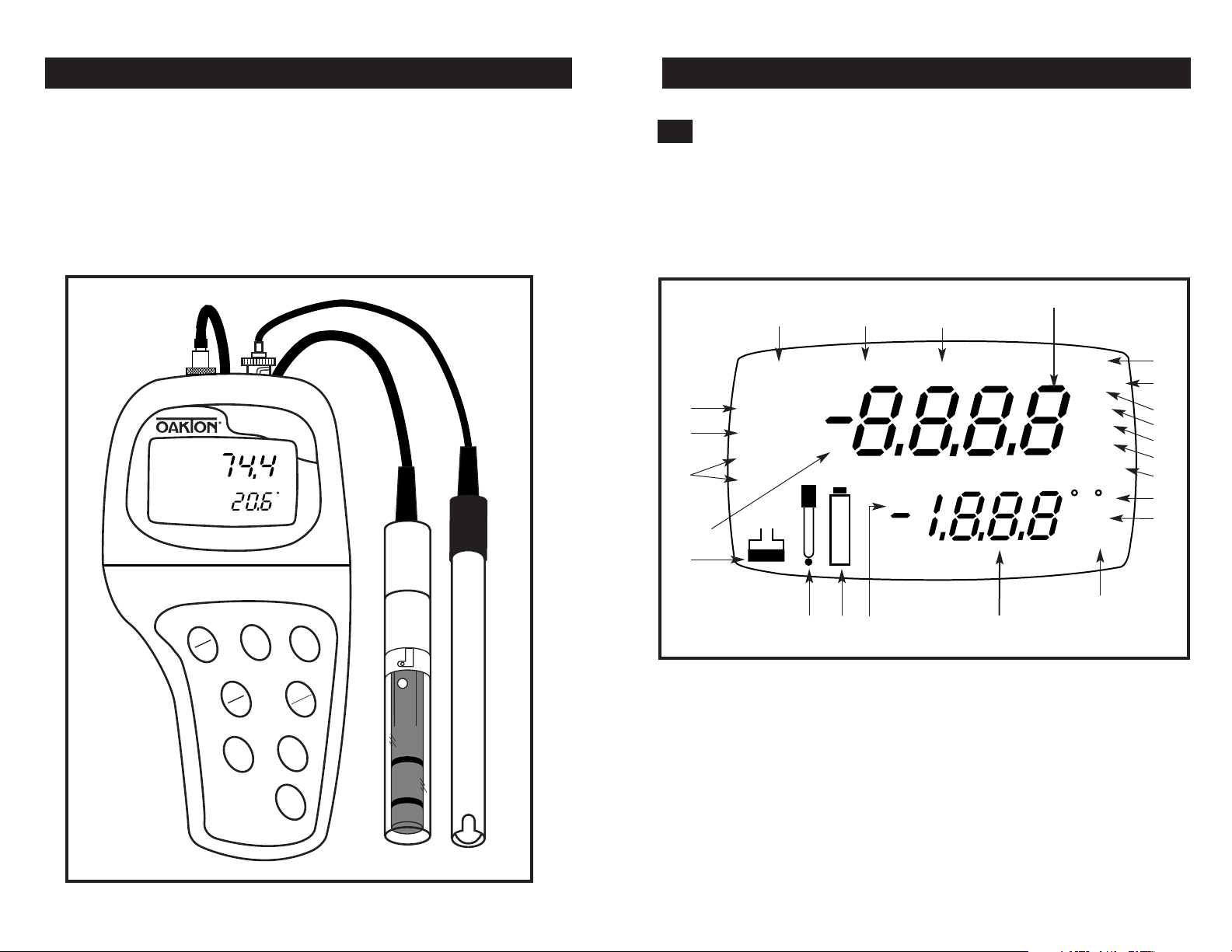
2. Display and Keypad Functions
2.1
Display
The LCD has a primary and secondary display.
• The primary display shows the measured pH or conductivity reading.
• The secondary display shows the temperature of the reading.
The display also shows error messages, keypad functions and program functions.
Primary display
1.
2.
3.
CAL
21
20.
SETUP
READY
HOLD
MEAS
K=
ON
19.
18.
17.
1. SETup mode indicator
2. MEASurement mode
indicator
3. CALibration indicator
4. mV indicator
5. % indicator
6. pH measurement
indicator
7. Millisiemens indicator
8. Microsiemens indicator
http://www.novatech-usa.com/Products/Laboratory-Equipment-Supply-Products Tel: (281) 359-8538 Toll Free:(866) 433-6682
OFF
ERR
15.
16.
14.
9. Parts per thousand
indicator
10.
Parts per million
indicator
11.
Temperature
indicators
12.
pH setup indicator
13.
Automatic
Temperature
Compensation
indicator
Secondary display
14.
ERRor indicator
15.
Low battery indicator
16.
Probe indicator
17.
Calibration indicator
18.
Cell constant indicator
19.
ON/OFF indicator
20.
HOLD indicator
21.
READY indicator
mV
pH
mS
µS
ppt
ppm
F
C
pH
ATC
13.
%
4.
5.
6.
7.
8.
9.
10.
11.
12.
54
Page 4
2.2
Keypad
The large membrane keypad makes the instrument easy to use. Each button, when
pressed, has a corresponding graphic indicator on the LCD.
ON/OFF............Powers and shuts off the meter.
HOLD ..............Freezes the measured reading. To activate, press HOLD while in
measurement mode. To release, press HOLD again.
NOTE:
When auto endpoint feature is switched on, meter automatically holds reading after 5 seconds of stability. The HOLD indicator
appears on the display. Press HOLD to release auto endpoint feature.
MODE..............Selects the measurement parameter. Press MODE to toggle between
pH, conductivity and TDS readings. In calibration mode, press
MODE to access temperature calibration.
CAL/MEAS......Toggles user between Calibration and Measurement mode. For
example, if you are in pH measurement mode, press CAL/MEAS to
enter pH calibration mode.
NOTE: Temperature calibration is available from calibration mode;
see page 16 for directions.
In advanced set-up mode: Press CAL/MEAS to return to main menu
from sub menus. Press CAL/MEAS again to return to measurement
mode from main menu.
ENTER ............Press to confirm values in Calibration mode and to confirm
selections in Setup mode.
RANGE............Press to switch to manual ranging in Conductivity (or TDS) mode.
▲▼ ..........Press in Setup mode to scroll through subgroups. Also lets
you increment/decrement the values in the conductivity and
temperature calibration modes.
SETUP..............Press to enter SETUP mode. SETUP mode lets you
customize meter preferences
and defaults, and view
calibration and probe data.
3. Preparation
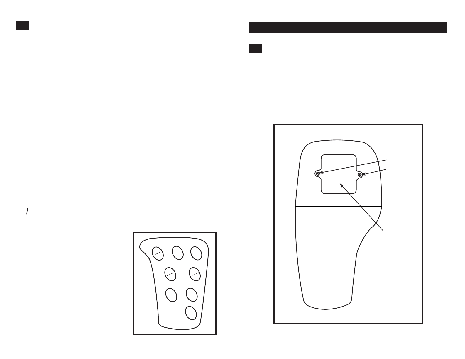
3.1
Inserting the Batteries
Four AAA batteries are included with your meter.
1. Use a Phillips screwdriver to remove the two screws holding the battery cover.
See figure below.
2. Lift off battery cover to expose batteries.
3. Insert batteries. Follow the diagram inside the cover for correct polarity.
4. Replace the battery cover into its original position. Screw cover back into place.
Remove these
two screws to
access battery
compartment
Battery
compartment
ON
OFF
http://www.novatech-usa.com/Products/Laboratory-Equipment-Supply-Products Tel: (281) 359-8538 Toll Free:(866) 433-6682
CAL
MEAS
▲
HOLD
ENTER
RANGE
▼
SETUP
MODE
76
Page 5
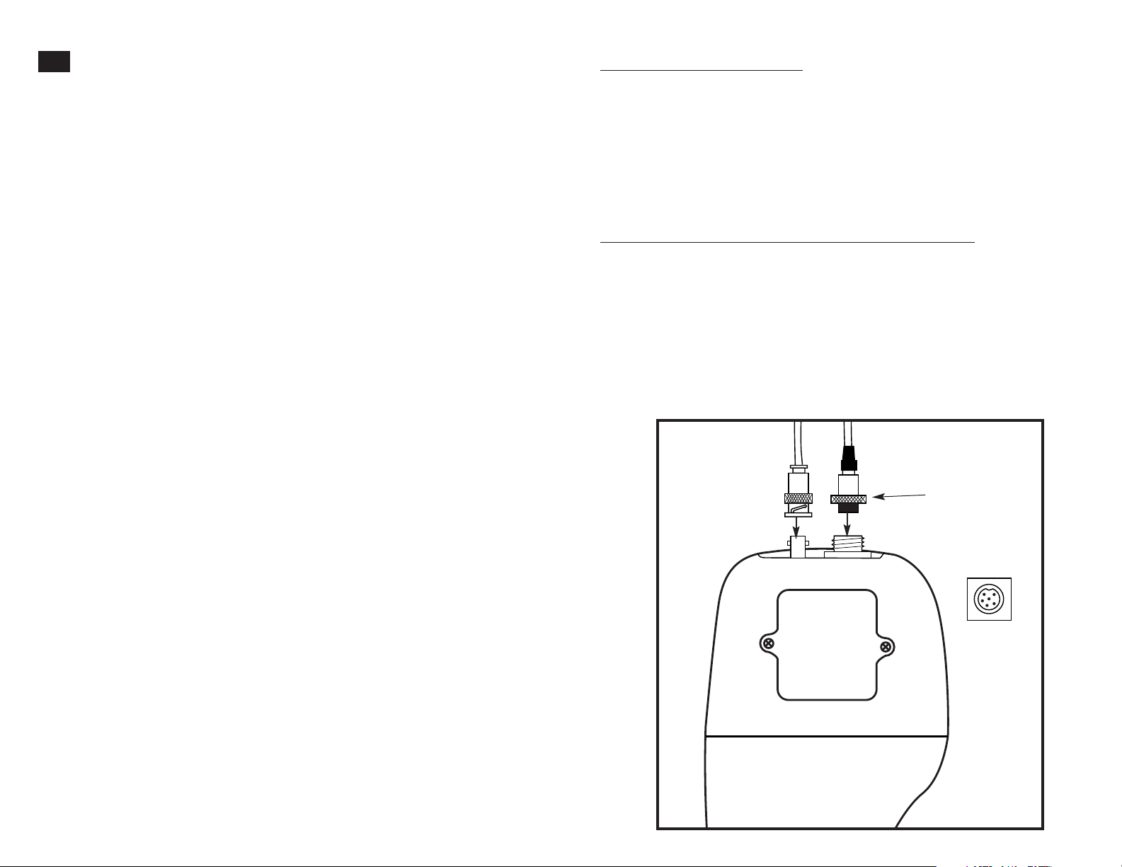
3.2
Probe information
Your meter includes two probes:
• pH electrode with BNC connector
• conductivity/TDS/temperature probe with a notched 6-pin connector
The temperature sensing element built into the conductivity probe will also
compensate for pH readings as long as both probes are in your solution at the
same time.
If you want to use an “All in One” pH probe with a built-in temperature element, or
if you want to use a separate temperature probe, you will need to disconnect the
conductivity/TDS probe to allow for connection of the separate temperature sensor.
You can use any standard pH electrode with a BNC connector with this meter.
Conductivity/TDS probes, “All in One” pH electrodes with a built-in temperature
element, and temperature probes require a probe with a notched 6-pin connector.
For replacement probes, see the “Accessories” section, pages 46-47.
NOTE: Keep connector dry and clean. Do not touch connector with soiled hands.
To connect the pH electrode:
1. Slide the BNC connector of the probe over the BNC connector socket on the
meter. Make sure the slots of the connector are in line with the posts of the
socket. Rotate and push the connector clockwise until it locks.
See figure below.
2. To remove probe, push and rotate the connector counterclockwise. While
holding onto the metal part of the connector, pull probe away from the meter.
CAUTION: Do not pull on the probe cord or the probe wires might disconnect.
To connect the conductivity/TDS/temperature probe:
1. Line up the notch and 6 pins on the meter with the holes in the 6-pin connector.
Push down and turn the locking ring clockwise to lock into place.
See figure below.
2. To remove probe, turn the locking ring counterclockwise on the probe connector.
Pull probe away from the meter.
NOTE: follow the same directions to connect an optional separate temperature
element.
CAUTION: Do not pull on the probe cord or the probe wires might disconnect.
pH electrode
(with BNC connector)
http://www.novatech-usa.com/Products/Laboratory-Equipment-Supply-Products Tel: (281) 359-8538 Toll Free:(866) 433-6682
conductivity/TDS?temperature probe
(with 6-pin connector)
locking ring
top view of 6-pin
connector—
conductivity/TDS
temperature probe
98
Page 6
4. Calibration
4.1
Important Information on Meter Calibration
When you recalibrate your meter, old calibration points are replaced on a “point
by point” basis in pH, and on a “range by range” basis in conductivity or TDS.
For example:
• pH:
if you previously calibrated your meter at pH 4.01, 7.00, and 10.01, and you
recalibrate at pH 7.00, the meter retains the old calibration data at pH 4.01 and
pH 10.01.
• Conductivity/TDS:
µS in the 0 to 1999 µS range and you recalibrate at 1500 µS (also in the 0 to 1999 µS
range), the meter will replace the old calibration data (1413 µS) in that range.
The meter will retain all calibration data in other ranges.
TDS values are proportional to conductivity values. Note that if you calibrate a
TDS value in an equivalent conductivity range, the TDS value will replace the
previous conductivity value, and vice versa.
To view current calibration points:
• pH: Program P1.0 in the SETUP section, page 26.
• Conductivity/TDS: Program P5.0 in the SETUP section, page 32.
To completely recalibrate your meter, or when you use a replacement probe,
it is best to clear old calibration data by resetting the meter.
To reset the meter to its factory defaults:
• pH: Program P4.0 in the SETUP section, page 31.
• Conductivity/TDS: Program P9.0 in the SETUP section, page 40.
NOTE: Resetting the meter will set meter to factory defaults.
Conductivity/TDS and pH must be reset separately.
For directions on how to calibrate your meter:
• See section 4.3 on pages 11-12 for pH calibration
• See section 4.4 on page 13-15 for conductivity and TDS calibration
• See section 4.5 on page 16 for Temperature Calibration
4.2
Preparing the Meter for Calibration
Before starting calibration, make sure you are in the correct measurement mode.
When you switch on the meter, the meter starts up in the units last used. For
example, if you shut the meter off in "pH" units, the meter will read "pH" units
when you switch the meter on.
Do not reuse calibration solutions after calibration. Contaminants in the solution can
affect the calibration, and eventually the accuracy of the measurements. See pages
46-47 for information on our high-quality calibration solutions.
if you previously calibrated your conductivity meter at 1413
http://www.novatech-usa.com/Products/Laboratory-Equipment-Supply-Products Tel: (281) 359-8538 Toll Free:(866) 433-6682
4.3
pH calibration
We recommend that you perform at least a 2-point calibration using standard buffers
that bracket (one above and one below) the expected sample range.
Preparing for pH calibration
This meter is capable of up to 5-point pH calibration to ensure accuracy across the
entire pH range of the meter. Select from the following buffer options:
pH 1.68, 4.01, 7.00, 10.01, and 12.45.
The meter automatically recognizes and calibrates to these standard buffer values,
which makes pH calibration faster and easier.
Be sure to remove the protective electrode storage bottle or rubber cap of the
probe before calibration or measurement. If the electrode has been stored dry,
wet the probe in tap water for 10 minutes before calibrating or taking readings to
saturate the pH electrode surface and minimize drift.
Wash your probe in deionized water after use, and store in electrode storage
solution. If storage solution is not available, use pH 4.0 or 7.0 buffer.
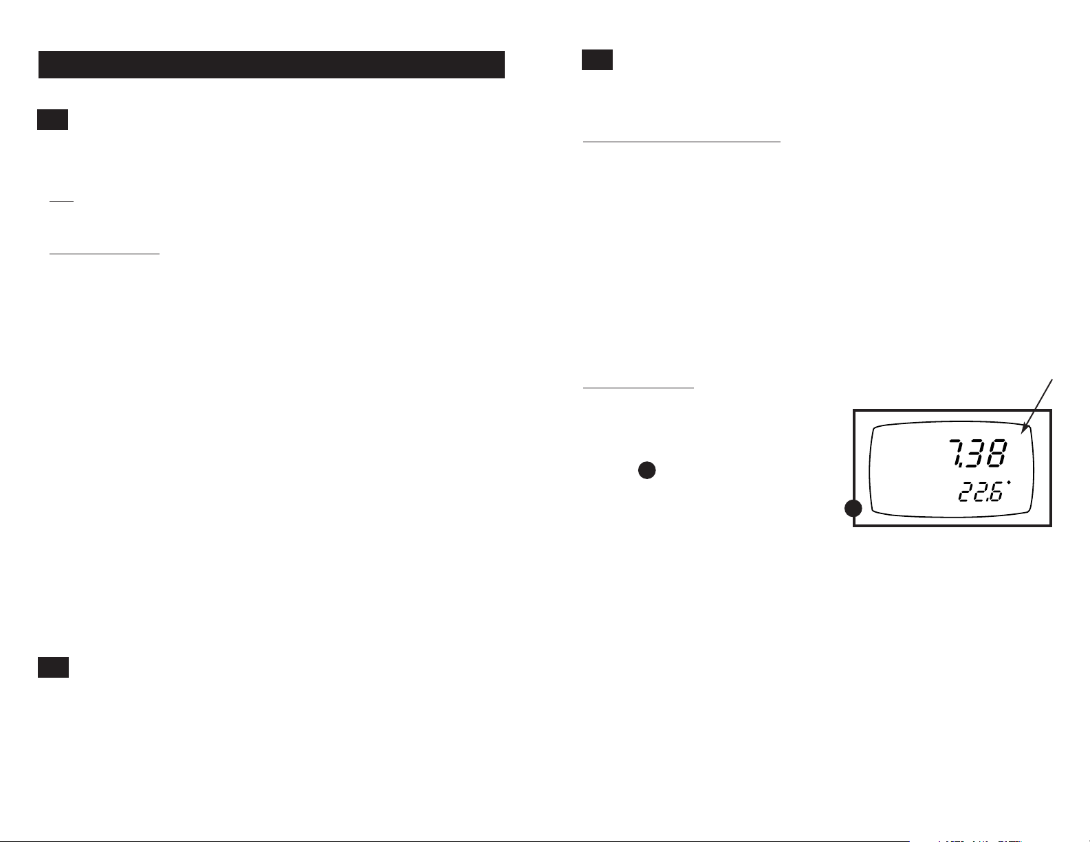
To calibrate pH:
1. If necessary, press the MODE key to
select pH measurement mode. The pH
indicator appears in the upper right hand
corner of the display.
See figure
A
2. Rinse the pH electrode thoroughly with
de-ionized water or a rinse solution. Do
not wipe the probe; this causes a build-up
of electrostatic charge on the glass surface.
3. Dip the pH electrode into the calibration
buffer. The end of the probe must be
completely immersed into the sample. Stir
the probe gently to create a homogeneous
sample.
NOTE: The temperature element is in the
conductivity cell. For temperature compensated readings, dip the conductivity cell into
the calibration buffer as well.
CONTINUED ON NEXT PAGE
A
READY
MEAS
pH
C
ATC
1110
Page 7
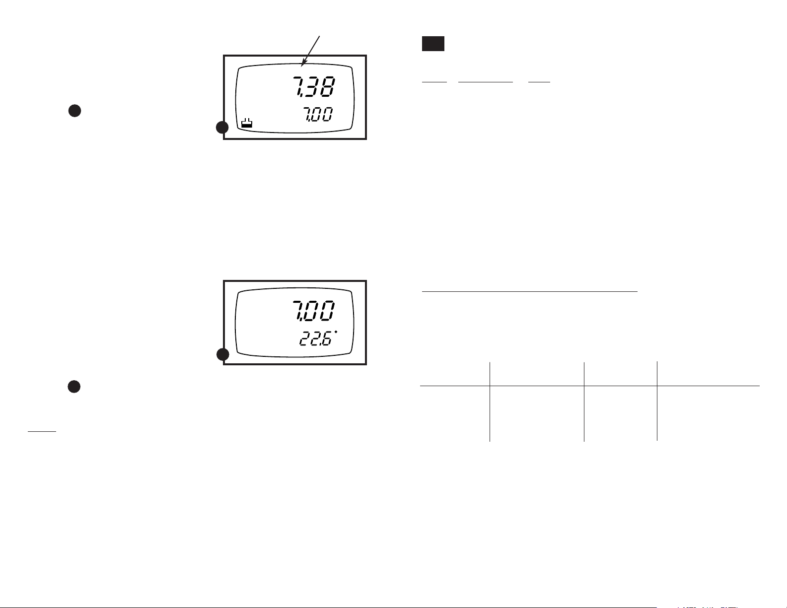
4. Press CAL/MEAS to enter pH calibration
mode. The CAL indicator lights. The
primary display will show the measured
reading while the smaller secondary
display will indicate the pH standard
READY
CAL
pH
buffer solution.
See figure
5. Wait for the measured pH value to
B
pH
B
stabilize. If the READY indicator has
been activated (set up program P3.1—
see page 28), the READY annunciator
lights when the reading is stable.
6. Press ENTER to confirm calibration.
The meter is now calibrated to the
current buffer. The lower display scrolls
through the remaining buffer options.
• If you are performing multipoint
calibration, go to step 7.
• If you are performing one-point
calibration, go to step 9.
7. Rinse the electrode with de-ionized
READY
MEAS
pH
water or a rinse solution, and place it
in the next pH buffer.
8. Follow steps 5 to 8 for additional
calibration points.
9. When calibration is complete,
press CAL/MEAS to return to pH
measurement mode.
See figure
C
C
C
ATC
Notes
To exit from pH Calibration mode without confirming calibration, DO NOT press
ENTER in step 6. Press CAL/MEAS instead.
If the selected buffer value is not within ±1.0 pH from the measured pH value: the
electrode and buffer icon blink and the ERR annunciator appears in the lower left
corner of the display.
To limit the number of pH buffer values available during calibration, see Set-up
program P3.2 on page 29.
4.3
Conductivity and TDS calibration
Calibrate up to 5-point conductivity or 5 point TDS calibration at one point per range:
Range
Conductivity: TDS:
R1 0.00-19.99 µS 0.00-9.99 ppm
R2 0.0-199.9 µS 10.0-99.9 ppm
R3 0-1999 µS 100-999 ppm
R4 0.00-19.99 mS 1.00-9.99 ppt
R5 0.0-199.9 mS 10.0-199.9 ppt
If you are measuring values in more than one range, make sure to calibrate each of
the ranges you are measuring. All new calibration data will over-ride existing stored
calibration data for each measuring range you calibrate.
• If you are measuring in ranges near to or greater than 20 mS (10 ppt), or near to
or lower than 100 µS (50 ppm), calibrate the meter at least once a week to get
specified ±1% F.S. accuracy.
• If you are measuring in the mid ranges and you washed the probe in deionized
water and stored it dry, calibrate the meter at least once a month.
• If you take measurements at extreme temperatures, calibrate the meter at least
once a week.
Preparing for conductivity/TDS calibration
For best results, select a standard value close to the sample value you are
measuring. Alternatively, use a calibration solution value that is approximately
2
⁄3 the full scale value of the measurement range you plan to use. For example,
in the 0 to 1999 µS conductivity range, use a 1413 µS solution for calibration.
See the table below for recommended calibration solution ranges:
Conductivity Recommended TDS Recommended
Range Cal. Solution Range Range Cal. Solution Range
0.00-19.99 µS 6.00 to 17.00 µS 0.00-9.99 ppm 3.00 to 8.50 ppm
0.0-199.9 µS 60.0 to 170.0 µS 10.0-99.9 ppm 30.0 to 85.0 ppm
0-1999 µS 600 to 1700 µS 100-999 ppm 300 to 850 ppm
0.00-19.99 mS 6.00 to 17.00 mS 1.00-9.99 ppt 3.00 to 8.50 ppt
0.0-199.9 mS 60.0 to 170.0 mS 10.0-199.9 ppt 30.0 to 170 ppt
Temperature coefficient: These meters are factory set to a temperature coefficient
of 2.1% per °C. For most applications this will provide good results. See
Program P8.1 on page 38 to set the temperature coefficient to a different value.
See Appendix 31, “Calculating Temperature Coefficients” on page 50 to determine
the appropriate temperature coefficient for your solution.
Normalization temperature: The factory default value for normalization temperature is 25°C. If you need to normalize to a value other than 25°C, see Program P8.2
on page 39.
CONTINUED ON NEXT PAGE
http://www.novatech-usa.com/Products/Laboratory-Equipment-Supply-Products Tel: (281) 359-8538 Toll Free:(866) 433-6682
1312
Page 8
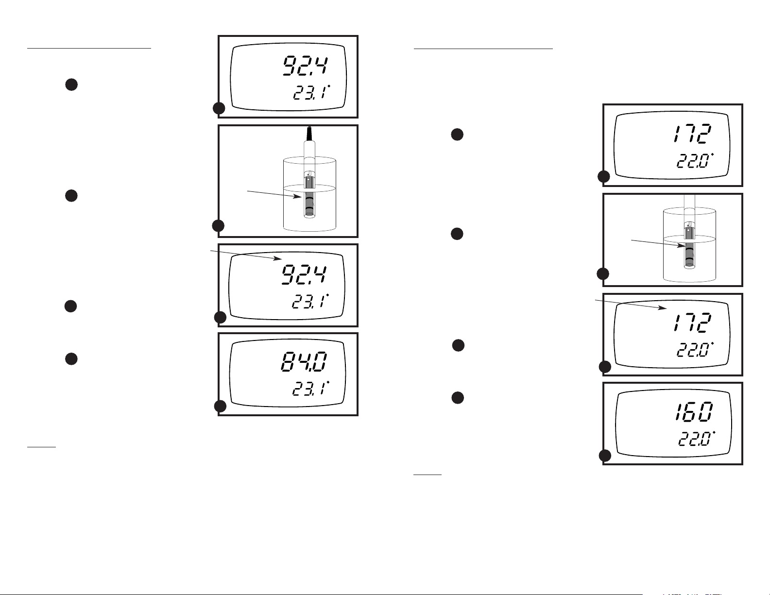
To calibrate conductivity:
1. If necessary, press the MODE key to
select conductivity mode.
See figure
A
2. Rinse the probe thoroughly with
de-ionized water or a rinse solution,
then rinse with a small amount of
calibration standard.
3. Dip the probe into the calibration
standard. Immerse the probe tip beyond
the upper steel band. Stir the probe gently
to create a homogeneous sample.
See figure
B
4. Wait for the measured conductivity
value to stabilize. If the READY indicator has been activated (set up program
P7.1—see page 34), the READY annunciator lights when the reading is stable.
5. Press CAL/MEAS to enter conductivity
calibration mode. The CAL indicator
will appear above the display.
See figure
C
6. Press the ▲ or ▼ to change the value on
the primary display to match the value of
the calibration standard.
See figure
D
7. Press ENTER to confirm the calibration
value. The meter returns to the MEAS
(measurement) mode.
8. Repeat steps 1-7 for other ranges.
A
Immerse
probe beyond
upper steel
band
B
C
D
READY
READY
READY
MEAS
µS
C
ATC
CAL
µS
C
ATC
CAL
µS
C
ATC
Notes
When entering calibration mode, the meter will display the factory default value. If
the meter was previously calibrated, the display may “jump” to the factory default
value when switching from measurement to calibration mode.
To exit from Conductivity Calibration mode without confirming calibration, DO NOT
press ENTER in step 6. Press CAL/MEAS instead. This will retain the meter’s old calibration data in the measuring range of the calibration.
You can offset the conductivity reading up to ±20% from the default setting. If your
measured value differs by more than ±20%, clean or replace probe as needed. See
page 47 for a wide selection of high-quality calibration standards.
http://www.novatech-usa.com/Products/Laboratory-Equipment-Supply-Products Tel: (281) 359-8538 Toll Free:(866) 433-6682
Calibrating for TDS directly
The factory default setting for TDS conversion factor is 0.5. If your solution has a different TDS factor, you can improve calibration accuracy by setting the TDS factor
prior to calibration. See SetUp Program P7.4 on page 37 for directions. See
Appendixes 1 and 2 on pages 48-49 to determine your exact TDS factor.
1. If necessary, press the MODE key to
select TDS mode.
See figure
A
2. Rinse the probe with de-ionized water or
a rinse solution, then rinse with a small
amount of calibration standard.
A
MEAS
READY
ppm
C
ATC
3. Dip the probe into the calibration
standard. Immerse the probe tip beyond
the upper steel band. Stir the probe gently
to create a homogeneous sample.
See figure
B
Immerse
probe beyond
upper steel
band
4. Wait for the measured TDS value to
stabilize. If the READY indicator has
been activated (set up program P7.1—
see page 34), the READY annunciator
lights when the reading is stable.
5. Press CAL/MEAS to enter TDS calibra-
tion mode. The CAL indicator will appear
above the display.
See figure
C
6. Press the ▲ or ▼ keys to change the
value on the primary display to match the
value of the calibration standard.
See figure
D
7. Press ENTER to confirm the calibration
value. The meter returns to the MEAS
(measurement) mode.
8. Repeat steps 1-7 for other ranges.
B
CAL
READY
ppm
C
ATC
C
CAL
READY
ppm
C
ATC
D
Notes
When entering calibration mode, the meter will display the factory default value. If
the meter was previously calibrated, the display may “jump” to the factory default
value when switching from measurement to calibration mode.
To exit from TDS Calibration mode without confirming calibration, DO NOT press
ENTER in step 6. Press CAL/MEAS instead. This will retain the meter’s old calibration
data in the measuring range of the calibration.
You can offset the TDS reading up to ±20% from the default setting. If your meas-
ured value differs by more than ±20%, clean or replace probe as needed.
1514
Page 9

4.5
Temperature calibration
The temperature sensor (located in the conductivity cell) is factory calibrated.
Calibrate your sensor only if you suspect sensor drift that may have occurred
over a long period of time or if you have a replacement probe.
Temperature calibration
1. Make sure the conductivity cell (or
alternative temperature element) is
attached to the 6-pin connector.
2. Switch the meter on. The ATC annuncia-
tor will appear at the right-hand side of
the LCD.
3. Press the CAL/MEAS key to enter
calibration mode (either pH or
conductivity). The CAL indicator will
appear above the primary display.
4. While in calibration mode, press
the MODE key to enter temperature
calibration mode. The primary display
shows the last set temperature value and
the secondary display shows the temperature reading with zero offset.
See figure
A
5. Dip the ATC element into a solution of
known temperature (i.e. a temperature
bath). Allow time for the temperature
element to stabilize.
A
CAL
F
ATC
6. Scroll with the ▼ and ▲ keys to set
the correct temperature value (i.e. the
temperature of the temperature bath).
You can adjust the reading in increments
of 0.1°C.
See figure
B
7. Once you have selected the correct
temperature, press the ENTER key.
The meter automatically returns to
pH measurement mode.
B
CAL
F
ATC
Notes
• You can offset the temperature reading up to ±5°C from the original reading.
• To exit this program without confirming the temperature calibration value, DO NOT
press ENTER in step 7. Press CAL/MEAS instead.
5. Measurement
5.1
Taking pH Measurements
To take readings:
1. Rinse the pH electrode with deionized
or distilled water before use to remove
any impurities adhering to the probe
body. If the pH electrode has dehydrated,
soak it for 30 minutes in electrode storage
solution or a 2M–4M KCl solution.
2. Press ON to switch on meter.
3. Press the MODE key to select pH
measurement mode. The MEAS annun-
ciator appears on the top center of the
LCD. The ATC indicator appears in the
lower right hand corner to indicate
Automatic Temperature Compensation.
See figure
NOTE: For pH manual temperature
compensation, you must disconnect the
conductivity cell from the 6-pin connector.
The ATC indicator will disappear from
the display. You also need to set a manual
temperature compensation value—see page
22 for directions.
4. Dip the pH electrode into the sample.
Since the conductivity cell contains the
temperature sensor, make sure it is also
immersed in your solution.
When dipping the probe into the sample,
the sensor or the glass bulb of the electrode
must be completely immersed into the
sample. Stir the probe gently in the sample
to create a homogenous sample.
5. Allow time for the reading to stabilize.
Note the reading on the display. If the
Ready indicator is selected on, it will
appear when the reading is stable. See
page 20 for more information.
6. Press the MODE key to toggle between
pH and conductivity readings.
A
MEAS
READY
A
pH
C
ATC
http://www.novatech-usa.com/Products/Laboratory-Equipment-Supply-Products Tel: (281) 359-8538 Toll Free:(866) 433-6682
1716
Page 10

5.2
Taking Conductivity or TDS Measurements
5.3
HOLD function
To take readings:
1. Rinse the probe with deionized or
distilled water before use to remove
any impurities adhering to the probe
body. Shake or air dry. To avoid
contamination or dilution of your
sample, rinse probe with a small
volume of your sample liquid.
2. Press ON to switch on meter.
3. Press the MODE key to select conduc-
tivity (or TDS) measurement mode. The
MEAS annunciator appears on the top
center of the LCD. The ATC indicator
appears in the lower right hand corner
to indicate Automatic Temperature
Compensation.
See figure
A
NOTE: For conductivity manual temperature compensation, you must deactivate the
temperature sensor built into the conductivity probe and set a manual temperature
compensation value. See pages 21-22 for
directions. The ATC indicator will disappear from the display.
4. Dip the probe into the sample.
When dipping the probe into the sample,
the tip of the probe must be immersed
above the second steel band. Stir the
probe gently in the sample to create a
homogenous sample.
See figure
B
5. Allow time for the reading to stabilize.
Note the reading on the display. If the
Ready indicator is selected on, it will
appear when the reading is stable. See
page 20 for more information.
6. Press the MODE key to toggle between
conductivity and pH readings.
READY
A
Immerse
probe beyond
upper steel
band
B
MEAS
µS
C
ATC
This feature lets you freeze your reading for
a delayed observation. HOLD can be used
any time when in MEAS mode.
1. To hold a measurement, press the
HOLD key while in measurement
mode. "HOLD" will appear on
the display.
See figure
C
2. To release the held value, press HOLD
again. Continue to take measurements.
NOTE: This meter shuts off automatically
C
READY
HOLD
MEAS
µS
F
ATC
after 20 minutes of nonuse. If the meter is
shut off either automatically or manually,
the HOLD value will be lost.
Taking measurements with READY indicator selected on
If the READY indicator has been activated, the READY annunciator lights when
the reading is stable. Switch the READY indicator on or off in Set up program
P7.1—see page 34 for directions.
Taking measurements with the auto endpoint feature selected on
When a reading is stable for more than 5 seconds, the auto endpoint feature will
automatically “hold” the reading. The “hold” indicator appears on the left side of
the display. Press the HOLD key to release the reading. Switch the Auto endpoint
feature on or off in Set up program P7.1—see page 34 for directions.
Notes
You can use the conductivity/TDS manual ranging function to select a specific range
in which your readings will appear. See page 20 for directions.
http://www.novatech-usa.com/Products/Laboratory-Equipment-Supply-Products Tel: (281) 359-8538 Toll Free:(866) 433-6682
1918
Page 11

5.4
Using manual ranging function: conductivity/TDS
When shipped from the factory, your meter automatically selects the range in which
your readings appear. The manual ranging function lets you select the specific range
in which you want to work.
From measurement mode:
1. To select the desired measuring range,
press the RANGE key while in
Conductivity measurement mode.
The first range will appear on the
display. The “MEAS” indicator blinks,
and the “Range” number flashes briefly
READY
MEAS
µS
in the lower display.
Range
Conductivity: TDS:
R1 0.00-19.99 µS 0.00-9.99 ppm
A
C
ATC
R2 0.0-199.9 µS 10.0-99.9 ppm
R3 0-1999 µS 100-999 ppm
R4 0.00-19.99 mS 1.00-9.99 ppt
R5 0.0-199.9 mS 10.0-199.9 ppt
See figure
A
2. Press the RANGE key again (if needed)
until desired range is selected.
3. To reselect the Auto-ranging function,
repeatedly press the RANGE key until
the “MEAS” indicator appears without
blinking.
Notes
This meter will not let you manually select a range in which the reading will be
overrange.
The meter resets to the Auto-ranging function once it is turned off. You will
have reset the manual ranging function each time you turn the meter off.
5.5
Selecting manual temperature compensation:
conductivity or TDS
For manual temperature compensation in conductivity or TDS mode, you must:
1. Deactivate the temperature element built into the conductivity/TDS probe.
2. Select a manual temperature compensation value (see page 22).
You can deactivate the temperature element (select manual temperature compensa-
tion) in Set Up Program P7.3.
From measurement mode
1. Press the Mode key to select
conductivity measurement mode.
2. Press Setup key to enter Set Up mode.
3. Press the ▲ and ▼ keys to scroll through
subgroups until you view parameter P7.0.
See figure
A
4. Press the ENTER key three times to
select parameter 7.3. The upper display
shows “ATC” and the lower display
shows “P7.3”.
See figure
B
5. Press the ENTER key again. The upper
display shows “ATC” and the lower
display shows “YES” or “NO”.
6. Press the ▲ and ▼ keys to select the
Automatic Temperature Compensation
off.
• YES = ATC on
• NO = ATC off (manual compensation)
See figure
C
7. Press the ENTER key to confirm
selection and to return to the subgroup
menu. Press the CAL/MEAS key to
return to measurement mode.
Note that the ATC indicator no longer
appears on the display.
Go to page 22 to select a manual temperature compensation value.
SETUP
mS
µS
ppt
ppm
A
SETUP
C
ATC
B
SETUP
C
ATC
SETUP
C
ATC
C
http://www.novatech-usa.com/Products/Laboratory-Equipment-Supply-Products Tel: (281) 359-8538 Toll Free:(866) 433-6682
2120
Page 12

5.6
CAL
SETUP
pH
SETUP
pH
SETUP
pH
MEAS
SETUP
pH
mS
SETUP
µS
mS
SETUP
µS
mS
SETUP
µS
mS
F
SETUP
C
µS
mS
MEAS
SETUP
µS
ppt
ppm
ppt
ppm
ppt
ppm
ppt
ppm
ppt
ppm
Selecting the manual temperature compensation value
To use manual temperature compensation, you need to enter the temperature
value of your process into the meter. This is the value at which readings will
manually temperature compensate. You can select any temperature between
0 and 100°C (32 and 212°F). Default value is 25°C (77°F).
To select a manual temperature compensation value:
1. Press the MODE key to select the meas-
urement mode in which you need to use
manual temperature compensation.
2. If necessary, select ATC off.
pH:
Conductivity/TDS:
see NOTE on page 17
see page 21
CAL
READY
When ATC is off, the ATC indicator
disappears from the lower right corner
of the display.
3. Press the CAL/MEAS key to enter
D
calibration mode. The CAL indicator
will appear above the primary display.
See figure
4. While in calibration mode, press
D
CAL
the MODE key to enter temperature
calibration mode. The primary display
shows the current temperature setting
and the secondary display shows the
last set temperature value.
See figure
E
E
5. Check the temperature of your sample
using an accurate thermometer.
6. Press the ▲ or ▼ keys to offset the
temperature to the measured value
from step 5.
See figure
7. Press ENTER to confirm the selected
temperature and to return to measure-
F
F
ment mode.
The meter will now compensate readings for the manually set temperature.
Notes
To exit this program without confirming the manual temperature compensation value,
DO NOT press ENTER in step 7. Press CAL/MEAS instead.
Setting the manual temperature compensation value for conductivity or TDS will change
the manual temperature compensation value for pH to the same value, and vice versa.
http://www.novatech-usa.com/Products/Laboratory-Equipment-Supply-Products Tel: (281) 359-8538 Toll Free:(866) 433-6682
CAL
6. Advanced set up functions
The advanced set up mode lets you customize your
meter’s preferences and defaults. Your OAKTON
waterproof meter features different sub groups that
organize all set-up parameters.
This meter blanks out sub groups that do not apply
to the measurement mode [conductivity/TDS or pH]
you are in when you enter Setup mode.
The full selection of available sub groups are:
µS
C
C
C
pH sub groups
1.
P1.0: Viewing pH calibration data
2. P2.0: Viewing pH probe data
3. P3.0: pH configuration
4. P4.0: Resetting meter to factory default
( pH settings)
Conductivity/TDS sub groups
5.
P5.0: Viewing conductivity (TDS) calibration data
6. P6.0: Viewing conductivity (TDS) probe data
7. P7.0: Conductivity (TDS) configuration
8. P8.0: Conductivity (TDS) temperature parameters
9. P9.0: Resetting meter to factory default
(conductivity/TDS settings)
See pages 24-25 for a more detailed overview
on the different parameters available in the
sub group modes.
2322
Page 13

6.1
CAL
SETUP
pH
mS
SETUP
µS
ppt
ppm
Advanced set-up mode detailed overview
Sub groups available from conductivity/TDS measurement mode
Press the SETUP key to enter Set up mode. Press the ▲ and ▼ keys to scroll through sub groups.
Sub groups available from pH measurement mode
P1.0: Viewing pH calibration data
P1.1 View previous pH calibration data (pH 1.68)
P1.2 View previous pH calibration data (pH 4.01)
P1.3 View previous pH calibration data (pH 7.00)
P1.4 View previous pH calibration data (pH 10.01)
Instructions on page 26
SETUP
pH
Instructions on page 27
SETUP
pH
Instructions on pages 28-30
P1.5 View previous pH calibration data (pH 12.45)
P2.0: Viewing pH electrode data
P2.1 View electrode offset
P2.2 View electrode slope
P3.0: pH configuration
P3.1 Ready indicator on or off /
auto endpoint on or off
P3.2 Select number of pH calibration points
P3.3 Select °F or °C
Instructions on page 32
SETUP
mS
µS
ppt
ppm
Instructions on page 33
SETUP
mS
ppt
ppm
µS
Instructions on pages 34-37
P5.0: Viewing Con./TDS calibration data
P5.1 View conductivity/TDS calibration data R1
R1 = 0.00-19.99 µS / 0.00-9.99 ppm
P5.2 View conductivity/TDS calibration data R2
R2 = 0.0-199.9 µS / 10.0-99.9 ppm
P5.3 View conductivity/TDS calibration data R3
R3 = 0-1999 µS / 100-999 ppm
P5.4 View conductivity/TDS calibration data R4
R4 = 0.00-19.99 mS / 1.00-9.99 ppt
P5.5 View conductivity/TDS calibration data R5
R5 = 0.0-199.9 mS / 10.0-199.9 ppt
P6.0: Viewing Con./TDS probe data
P6.1 View effective cell constant R1
R1 = 0.00-19.99 µS / 0.00-9.99 ppm
P6.2 View effective cell constant R2
R2 = 0.0-199.9 µS / 10.0-99.9 ppm
P6.3 View effective cell constant R3
R3 = 0-1999 µS / 100-999 ppm
P6.4 View effective cell constant R4
R4 = 0.00-19.99 mS / 1.00-9.99 ppt
P6.5 View effective cell constant R5
R5 = 0.0-199.9 mS / 10.0-199.9 ppt
P7.0: Con./TDS configuration
P7.1 Ready indicator on or off /
auto endpoint on or off
P7.2 Select °F or °C
P7.3 Select ATC/Manual Temperature Compensation
P7.4 Set TDS factor
MEAS
SETUP
Instructions on page 31
pH
P4.0: Reset to factory default (pH)
Reset pH data to factory default settings
SETUP
C
mS
µS
ppt
ppm
F
P8.0: Temperature parameters
P8.1 Set temperature coefficient
P8.2 Set normalization temperature
Instructions on pages 38-39
MEAS
SETUP
mS
µS
ppt
ppm
Instructions on page 40
http://www.novatech-usa.com/Products/Laboratory-Equipment-Supply-Products Tel: (281) 359-8538 Toll Free:(866) 433-6682
P9.0: Reset to factory default (Con./TDS)
Reset conductivity data to factory default settings
2524
Page 14

6.2
P1.0: Viewing previous pH calibration data
6.3
P2.0: Viewing pH electrode data
This mode lets you recall previous pH calibration data, which lets you know at which
points this meter was previously calibrated. This is a “view only” mode.
From measurement mode:
1. Press the Mode key to select pH
measurement mode.
2. Press the Set up key to enter Set Up
mode.
See figure
A
SETUP
CAL
pH
3. Press the ▲ and ▼ keys to scroll
through subgroups until you view
parameter P1.0.
A
4. Press the ENTER key repeatedly to
view previous calibration data.
P1.1 = pH 1.68
P1.2 = pH 4.01
P1.3 = pH 7.00
P1.4 = pH 10.01
P1.5 = pH 12.45
See figure
B
SETUP
pH
B
5. When you have scrolled through all
calibration data, you will automatically
return to the subgroup menu. Press the
CAL/MEAS key to return to measurement mode.
Notes
If there is no previous calibration data at a
particular point, the primary display will
show “– – –”.
See figure
C
SETUP
pH
C
Program 2 has two “view only”options that lets you check the pH electrode
parameters for diagnostic purposes. It lets you view:
P2.1: Electrode offset
P2.2 Electrode slope
From measurement mode
1. Press the Mode key to select pH
measurement mode.
SETUP
2. Press the Setup key to enter Set Up
mode.
3. Press the ▲ and ▼ keys to scroll
A
through subgroups until you view
parameter P2.0.
See figure
4. Press the ENTER key to select
parameter P2.1.
A
SETUP
5. The display shows the electrode offset
value (the mV offset at pH 7.00). If you
have not calibrated at any buffer, the
primary display shows 0.00 mV.
See figure
B
B
6. Press the ENTER key to select
parameter P2.2.
SETUP
7. The display shows electrode slope
in percentage. Slope displayed is
the average slope based on the pH
calibrations. Default setting is 100.0.
See figure
C
C
8. Press the ENTER key to return to the
subgroup menu. Press the CAL/MEAS
key to return to measurement mode.
pH
mV
pH
%
pH
http://www.novatech-usa.com/Products/Laboratory-Equipment-Supply-Products Tel: (281) 359-8538 Toll Free:(866) 433-6682
2726
Page 15

6.4
P3.0: pH measurement configuration
P3.1: READY indicator and auto endpoint function
This program lets you select:
• “READY
• “READY
• Auto endpoint function on.
it is stable for more than 5 seconds. The display automatically freezes, and the
HOLD indicator appears on the left side of the display. Press the HOLD key to
release the display and access other functions.
From measurement mode
1. Press the Mode key to select pH
measurement mode.
2. Press Setup key to enter Set Up mode.
3. Press the ▲ and ▼ keys to scroll
through subgroups until you view
parameter P3.0.
See figure
4. Press the ENTER key to select
parameter 3.1.
See figure
5. Press the ▲ and ▼ keys to select the
configuration you require.
•OFF switches the READY indicator off.
•ON switches the READY indicator on.
•ON and HOLD together switches the
auto endpoint feature on.
6. Press the ENTER key to confirm selec-
tion and to proceed to step 4 of P.3.2.
Press the CAL/MEAS key twice to return
to measurement mode.
Notes
indicator on” to indicate when the reading is stable.
indicator off” for faster meter response.
Select auto endpoint on to “hold” the reading when
SETUP
A
A
SETUP
READY
ON
B
SETUP
READY
OFF
SETUP
READY
HOLD
ON
pH
P3.2: Selecting number of pH calibration points
Program P3.2 lets you select the number of pH calibration points the meter will use
in calibration mode: 2, 3, 4, or 5. The meter will automatically exit calibration mode
after you have calibrated to your selected number of points.
From measurement mode
1. Press the Mode key to select pH
measurement mode.
2. Press Setup key to enter Set Up mode.
3. Press the ▲ and ▼ keys to scroll through
subgroups until you view parameter P3.0.
See figure
C
4. Press the ENTER key twice to select
parameter 3.2.
See figure
D
5. Press the ▲ and ▼ keys to select 2, 3, 4,
or 5 point pH calibration.
6. Press the ENTER key to confirm selection
and to proceed to step 5 of P.3.3. Press the
CAL/MEAS key twice to return to measurement mode.
SETUP
pH
C
SETUP
READY
ON
D
Meter default is set for Ready indicator on,
and auto endpoint function off.
You can also change the Ready indicator and
auto endpoint function in Program P7.1
(available from conductivity/TDS mode).
Any changes you make to the Ready indicator/ auto endpoint function in pH mode will
also change in conductivity mode.
http://www.novatech-usa.com/Products/Laboratory-Equipment-Supply-Products Tel: (281) 359-8538 Toll Free:(866) 433-6682
B
2928
Page 16

P3.3 Selecting °C or °F
This meter lets you select between °C and °F units for temperature readings.
From measurement mode
1. Press the Mode key to select pH
measurement mode.
SETUP
pH
2. Press Setup key to enter Set Up mode.
3. Press the ▲ and ▼ keys to scroll through
subgroups until you view parameter P3.0.
See figure
E
E
4. Press the ENTER key four times to
select parameter 3.3.
See figure
F
5. Press the ▲ and ▼ keys to toggle
between °C and °F.
SETUP
C
6. Press the ENTER key to confirm selec-
tion and to return to the subgroup menu.
Press the CAL/MEAS key to return to
measurement mode.
SETUP
F
F
Notes
You can also switch between °C and °F in Program P7.2 (available from conductivity/
TDS mode). If you switch between °C and °F in pH mode, the meter will also switch
in conductivity mode.
6.5
P4.0: Resetting to factory default settings (pH)
This program lets you reset all pH parameters to factory default settings. This
clears all calibration data any other pH setup functions you might have changed.
The following settings will remain as you have set them:
• temperature unit of measure (°C or °F)
• The temperature offset calibration value
• All conductivity/TDS calibration data and parameters
From measurement mode
1. Press the Mode key to select pH
SETUP
pH
MEAS
measurement mode.
2. Press Setup key to enter Set Up mode.
3. Press the ▲ and ▼ keys to scroll through
subgroups until you view parameter
“P4.0” in the lower display.
See figure
A
4. Press the ENTER key.
See figure
B
A
MEAS
SETUP
pH
5. Press the ▲ and ▼ keys to toggle
between NO and YES.
• NO retains current settings
• YES resets to factory default settings
6. Press the ENTER key to confirm
SETUP
MEAS
pH
selection and to return to measurement
mode.
B
Notes
To reset all conductivity and TDS data, see page 40.
See page 51 for a table of factory default settings.
30 31
http://www.novatech-usa.com/Products/Laboratory-Equipment-Supply-Products Tel: (281) 359-8538 Toll Free:(866) 433-6682
Page 17

6.6
P5.0: Viewing previous conductivity/TDS calibration data
6.7
P6.0: Viewing conductivity/TDS probe data
This mode lets you recall previous conductivity or TDS calibration data, which lets
you know at which points this meter was previously calibrated. This is a “view only”
mode.
TDS values are proportional to conductivity values. Note that if you calibrate a TDS
value in an equivalent conductivity range, the TDS value will replace the previous
conductivity value, and vice versa.
From measurement mode:
1. Press the Mode key to select
conductivity or TDS measurement
mode.
2. Press the Set up key to enter Set Up
mode.
See figure
A
SETUP
mS
µS
ppt
ppm
A
3. Press the ▲ and ▼ keys to scroll
through subgroups until you view
parameter P5.0.
4. Press the ENTER key repeatedly to
view previous calibration data.
Range
Conductivity: TDS:
SETUP
CAL
µS
P5.1 (R1) 0.00-19.99 µS 0.00-9.99 ppm
P5.2 (R2) 0.0-199.9 µS 10.0-99.9 ppm
P5.3 (R3) 0-1999 µS 100-999 ppm
B
P5.4 (R4) 0.00-19.99 mS 1.00-9.99 ppt
P5.5 (R5) 0.0-199.9 mS 10.0-199.9 ppt
See figure
B
5. When you have scrolled through all
calibration data, you will automatically
return to the subgroup menu. Press the
CAL/MEAS key to return to measurement mode.
SETUP
CAL
Program 3 has five "view only" options that let you check your conductivity/TDS
probe’s parameters for diagnostic purposes. These options show you the effective cell
constant for each range. The cell constant is adjusted according to your calibration.
From measurement mode:
1. Press the Mode key to select
conductivity or TDS measurement
mode.
SETUP
mS
µS
ppt
ppm
1. Press the Set up key to enter Set Up
mode.
2. Press the ▲ and ▼ keys to scroll
A
through subgroups until you view
parameter P6.0.
See figure
A
SETUP
3. Press the ENTER key repeatedly
to view the effective cell constant for
each range.
Range
Conductivity: TDS:
P6.1 (R1) 0.00-19.99 µS 0.00-9.99 ppm
P6.2 (R2) 0.0-199.9 µS 10.0-99.9 ppm
P6.3 (R3) 0-1999 µS 100-999 ppm
P6.4 (R4) 0.00-19.99 mS 1.00-9.99 ppt
P6.5 (R5) 0.0-199.9 mS 10.0-199.9 ppt
See figure
B
B
K=
4. When you have scrolled through all
probe data, you will automatically
return to the subgroup menu. Press
the CAL/MEAS key to return to
measurement mode.
Notes
Notes
If there is no previous calibration data at a
particular point, the primary display will
show “– – –”.
See figure
C
http://www.novatech-usa.com/Products/Laboratory-Equipment-Supply-Products Tel: (281) 359-8538 Toll Free:(866) 433-6682
Cell constants will degrade with time and
usage. You can use this feature to alert you
to when your probe needs cleaning or to
C
when you need to replace your probe.
3332
Page 18

6.8
P7.0: Conductivity/TDS measurement configuration
P7.1: READY indicator and auto endpoint function
P7.2 Selecting °C or °F
This meter lets you select between °C and °F units for temperature readings.
This program lets you select:
• “READY
• “READY
• Auto endpoint function on.
indicator on” to indicate when the reading is stable.
indicator off” for faster meter response.
Select auto endpoint on to “hold” the reading when
it is stable for more than 5 seconds. The display automatically freezes, and the
HOLD indicator appears on the left side of the display. Press the HOLD key to
release the display and access other functions.
From measurement mode
1. Press the Mode key to select
conductivity or TDS measurement mode.
SETUP
2. Press Setup key to enter Set Up mode.
3. Press the ▲ and ▼ keys to scroll
through subgroups until you view
parameter P7.0.
See figure
A
4. Press the ENTER key to select
parameter 7.1.
See figure
B
A
SETUP
READY
ON
5. Press the ▲ and ▼ keys to select the
configuration you require.
•ON switches the READY indicator on.
•OFF switches the READY indicator off.
•ON and HOLD together switches the
auto endpoint feature on.
6. Press the ENTER key to confirm selection
and to proceed to step 4 of P.7.2. Press the
CAL/MEAS key twice to return to measurement mode.
Notes
Meter default is set for Ready indicator on,
and auto endpoint function off.
You can also change the Ready indicator
and auto endpoint function in Program P3.1
(available from pH mode). Any changes
you make to the Ready indicator/ auto endpoint function in conductivity mode will
also change in pH mode.
SETUP
READY
OFF
SETUP
READY
HOLD
ON
B
mS
µS
ppt
ppm
From measurement mode
1. Press the Mode key to select
conductivity or TDS measurement mode.
2. Press Setup key to enter Set Up mode.
SETUP
mS
µS
ppt
ppm
3. Press the ▲ and ▼ keys to scroll through
subgroups until you view parameter P7.0.
See figure
C
C
4. Press the ENTER key four times to select
parameter 7.2.
See figure
D
5. Press the ▲ and ▼ keys to toggle between
°C and °F.
SETUP
C
6. Press the ENTER key to confirm selection
and to proceed to step 4 of P7.3. Press the
CAL/MEAS key twice to return to measurement mode.
SETUP
F
D
Notes
You can also switch between °C and °F in Program P3.3 (available from pH mode).
If you switch between °C and °F in conductivity mode, the meter will also switch in
pH mode.
http://www.novatech-usa.com/Products/Laboratory-Equipment-Supply-Products Tel: (281) 359-8538 Toll Free:(866) 433-6682
3534
Page 19

P7.3 Selecting Automatic or Manual Temperature Compensation
P7.4 Setting the TDS factor
This feature lets you select between Automatic Temperature Compensation (ATC)
and Manual Temperature Compensation for conductivity (it lets you deactivate the
temperature sensor in the conductivity/TDS probe). Meter default is ATC.
From measurement mode
1. Press the Mode key to select
conductivity or TDS measurement mode.
2. Press Setup key to enter Set Up mode.
SETUP
mS
µS
ppt
ppm
3. Press the ▲ and ▼ keys to scroll through
subgroups until you view parameter P7.0.
See figure
E
E
4. Press the ENTER key three times to
select parameter 7.3. The upper display
shows “ATC” and the lower display
shows “P7.3”.
See figure
F
5. Press the ENTER key again. The upper
display shows “ATC” and the lower
display shows “YES” or “NO”.
See figure
G
6. Press the ▲ and ▼ keys to select the
Automatic Temperature Compensation on
of off.
• YES = ATC on
• NO = ATC off (manual compensation)
7. Press the ENTER key to confirm selection
and to proceed to step 4 of P7.4. menu.
Press the CAL/MEAS key twice to return
to measurement mode.
SETUP
C
ATC
F
SETUP
C
ATC
SETUP
C
ATC
G
The concentration of salts dissolved in solution increases the conductivity of that
solution. This relationship varies from salt to salt and is roughly linear over a given
range for a given salt. The TDS conversion factor is the number used by the meter to
convert from conductivity to TDS.
To determine the conductivity to TDS conversion factor for your solution:
• Appendix 1 on page 48 lists some commonly used conversion factors.
• Appendix 2 on page 49 describes how to calculate the TDS conversion factor for
other solutions.
You can set the TDS conversion factor between 0.4 and 1.0; meter default is 0.5.
From measurement mode
1. Press the Mode key to select
conductivity or TDS measurement mode.
2. Press Setup key to enter Set Up mode.
SETUP
mS
µS
ppt
ppm
3. Press the ▲ and ▼ keys to scroll through
subgroups until you view parameter P7.0.
See figure
H
H
4. Press the ENTER key five times to select
parameter 7.4. The upper display shows
“tdS” and the lower display shows
“P7.4”.
See figure
I
5. Press the ENTER key again. The upper
display shows a value and the lower
display shows “tdS”.
See figure
J
6. Calculate the TDS factor of your
solution. See Appendix 2 on page 49
for information on how to calculate the
TDS factor.
7. Press the ▲ and ▼ keys to select your
calculated TDS conversion factor.
SETUP
ppt
ppm
I
SETUP
ppt
ppm
J
8. Press the ENTER key to confirm
selection and to return to the subgroup
menu. Press the CAL/MEAS key to
return to measurement mode.
http://www.novatech-usa.com/Products/Laboratory-Equipment-Supply-Products Tel: (281) 359-8538 Toll Free:(866) 433-6682
3736
Page 20

6.9
P8.0: Temperature Settings
P8.1 Selecting the temperature coefficient
The temperature coefficient is the amount of change in conductivity per degree of
temperature; it is expressed in percent per °C or °F. Entering the exact temperature
coefficient of your solution lets you accurately compensate temperature for almost
any solution*. You can adjust 0.0 to 10.0% per °C or °F. Meter default is 2.1% per °C
or °F.
From measurement mode
1. Press the Mode key to select
conductivity or TDS measurement mode.
2. Press Setup key to enter Set Up mode.
3. Press the ▲ and ▼ keys to scroll through
subgroups until you view parameter P8.0.
See figure
A
4. Press the ENTER key to select
parameter 8.1. The display shows “T.CO”
on the upper display.
See figure
B
5. Press the ENTER key again.. The upper
display shows the temperature coefficient
and the lower display shows “T.CO”.
See figure
C
6. Press the ▲ and ▼ keys to select the tem-
perature coefficient of your solution.
7. Press the ENTER key to confirm selection
and to proceed to step 4 of P.8.2. Press the
CAL/MEAS key twice to return to measurement mode.
SETUP
mS
µS
ppt
ppm
C
F
A
SETUP
C
F
B
SETUP
C
P8.2 Selecting the normalization temperature
Your meter will normalize its conductivity measurements to a standard temperature
that you can select. You can adjust the normalization temperature from 15 to 30°C
(59 to 86°F). Meter default is 25°C (77°F).
From measurement mode
1. Press the Mode key to select
conductivity or TDS measurement mode.
2. Press Setup key to enter Set Up mode.
3. Press the ▲ and ▼ keys to scroll through
subgroups until you view parameter P8.0.
See figure
D
4. Press the ENTER key three times to
select parameter 8.2. The display shows
“t.nr” on the upper display.
See figure
E
5. Press the ENTER key again. The
upper display shows the normalization
temperature and the lower display
shows “t.nr”.
See figure
F
6. Press the ▲ and ▼ keys to select the
normalization temperature.
7. Press the ENTER key to confirm selection
and to return to the subgroup menu. Press
the CAL/MEAS key to return to measurement mode.
SETUP
mS
µS
ppt
ppm
C
F
D
SETUP
C
F
E
SETUP
C
F
Notes
* If you do not know the temperature coeffi-
cient of your solution you can determine
the correct value using the formula in
Appendix 3
Coefficients” on page 50.
“Calculating Temperature
http://www.novatech-usa.com/Products/Laboratory-Equipment-Supply-Products Tel: (281) 359-8538 Toll Free:(866) 433-6682
3938
Page 21

6.10
P9.0: Resetting to factory default settings (conductivity/TDS)
This program lets you reset all conductivity parameters to factory default settings.
This clears all calibration data any other conductivity setup functions you might
have changed. The following settings will remain as you have set them:
• temperature unit of measure (°C or °F)
• The temperature offset calibration value
• All pH calibration data and parameters
7. Probe Care and Maintenance
7.1
pH electrode care
Since your pH electrode is susceptible to dirt and contamination, clean it every one
to three months depending on the extent and condition of use. For specialty electrode care, consult the instruction manual included with your electrode.
From measurement mode
1. Press the Mode key to select
conductivity measurement mode.
2. Press Setup key to enter Set Up mode.
3. Press the ▲ and ▼ keys to scroll through
subgroups until you view parameter
“P5.0” in the lower display.
See figure
A
4. Press the ENTER key.
See figure
B
5. Press the ▲ and ▼ keys to toggle
between NO and YES.
• NO retains current settings
• YES resets to factory default settings
6. Press the ENTER key to confirm
selection and to return to measurement
mode.
Notes
To clear all pH data, see page 31.
See page 51 for a table of factory default settings.
pH electrode storage
MEAS
SETUP
mS
µS
ppt
ppm
For best results, always keep the pH bulb wet. Use the protective electrode storage
bottle or rubber cap filled with electrode storage solution to store your electrode (see
page 46 for ordering information). Also, you can store in a pH 4 buffer with 1/100
part of saturated KCl. Other pH buffers are OK for storage, but NEVER use distilled
water for storage.
A
After measuring
1. Rinse the pH electrode and reference junction in de-ionized water.
MEAS
SETUP
mS
µS
ppt
ppm
MEAS
SETUP
mS
µS
ppt
ppm
B
2. Store the electrode as recommended above in “pH electrode storage,” or as
recommended by the manufacturer.
3. Prior to next use, rinse the liquid junction with de-ionized water and tap dry—
never wipe electrode. If this does not restore electrode to normal response, see
“Reactivating the pH electrode” section below.
pH electrode cleaning
Salt deposits: dissolve the deposits by immersing the electrode in tap water for ten
to fifteen minutes. Ten thoroughly rinse with distilled water.
Oil/grease film: wash electrode pH bulb gently in some detergent and water. Rinse
electrode tip with distilled water or use a general purpose electrode cleaner (see
page 40 for ordering information).
Clogged reference junction: heat a diluted KCl solution to 60 to 80°C. Place the
sensing part of the electrode into the heated solution for about 10 minutes. Allow the
electrode to cool in some unheated KCl solution.
Protein deposits: prepare a 1% pepsin solution in 0.1 M of HCl. Set the electrode in
the solution for five to ten minutes. Rinse the electrode with distilled water.
Reactivating the pH electrode
If stored and cleaned properly, your pH electrode should be ready for immediate
use. However, a dehydrated bulb may cause sluggish response. To rehydrate the
bulb, immerse the electrode in a pH 4 buffer solution for 10 to 30 minutes. If this
fails, the electrode requires activation. Never touch or rub glass bulb. Contact
builds up an electrostatic charge.
CONTINUED ON NEXT PAGE
http://www.novatech-usa.com/Products/Laboratory-Equipment-Supply-Products Tel: (281) 359-8538 Toll Free:(866) 433-6682
4140
Page 22

pH electrode activation (for glass bodied electrodes only)
WARNING: Only qualified persons proficient with the safe handling of dangerous
chemicals should perform the procedure below. Provide proper containers, fume
hoods, ventilation, and waste disposal. Safety goggles and protective clothing must
be worn while performing this procedure. If possible, replace with another electrode
instead of performing this reactivation procedure.
1. Dip or stir the pH electrode in alcohol for 5 minutes.
2. Leave the electrode in tap water for 15 minutes.
3. Dip and stir the electrode in concentrate acid (such as HCl or H
4. Repeat step 2.
5. Dip and stir in strong base (NaOH) for five minutes.
6. Leave for 15 minutes in distilled or deionized water.
7. Now test with standard calibration buffer solutions to see if the electrode yields
acceptable results. You may repeat step 3 through 6 up to three times for better
response. If the response does not improve, then your electrode is no longer
functioning. Replace with a new electrode—call your OAKTON Distributor for more
information.
7.2
Conductivity/TDS probe care
Keep the conductivity/TDS probe clean. Rinse the probe
twice, and gently swirl it while you take readings. For
best accuracy, soak a dry probe for at least 5 to 10 minutes or longer before calibration. Rinse the probe with
deionized or tap water before storing. Never scratch the
platinum portions with a hard substance. Do not strike
the probe against any hard surface.
Do not make continuous contact with your solutions.
Readings will rise over a
period of time while you soak your probe.
Do not immerse the probe in oily solutions. Clean the
electrode thoroughly by stirring it in a mild detergent
bath or isopropyl alcohol. Wipe the probe with a soft tissue paper. Rinse thoroughly in tap water and then in
deionized water. Recalibrate the meter after cleaning the
probe.
The conductivity/TDS probe included with your meter
features a removable probe guard to make cleaning easy.
To remove probe guard:
1. Grip yellow probe guard and twist
clockwise. The locking notch will release.
2. Slide probe guard off end of probe.
) for 5 minutes.
2SO4
Probe model
WD-35608-50
locking
notch
twist probe
guard
clockwise
to remove
8. Troubleshooting
Problem Cause Solution
Power on but a) Batteries not in place. a) Check that batteries are in
no display place and making good
contact.
b) Batteries not in correct b) Reinsert batteries with
polarity (+ and –). correct polarity.
c) Weak batteries. c) Replace batteries.
Not responding a) HOLD mode in operation. a) Cancel HOLD mode.
to key press
Unstable a) Air bubbles in probe. a) Tap probe to remove bubbles.
readings
“OR” on upper a) Probe is shorted. a) Test probe. Make sure probe
display is fully connected to meter.
Temperature reading a) Temperature of solution a) Heat or cool solution.
erratic or lower is out of range
display reads “OR”
Slow response a) Dirty/Oily probe. a) Clean probe. See "Probe
b) Damaged key pad. b) Return to dealer.
c) Internal program error. c) Reset all internal programs
by reinserting batteries.
b) Dirty probe. b) Clean the probe and
recalibrate.
c) Probe not deep c) Make sure sample entirely
enough in sample. covers the probe sensor(s).
d) External noise pickup d) Move or switch off
or induction caused by interfering motor.
nearby electric motor.
e) Broken probe. e) Replace probe. See page 46.
b) Probe is in an b) Use different solution.
out-of range solution.
c) Broken probe. c) Replace probe. See page46.
Care & Maintenance",
pages 41-42.
http://www.novatech-usa.com/Products/Laboratory-Equipment-Supply-Products Tel: (281) 359-8538 Toll Free:(866) 433-6682
4342
Page 23

9. Error Messages
10. Specifications
LCD
Display
Err Unrecognized input Wrong input in Release key. Select
annunciator from keypad selected mode. valid operations
CAL & Err Calibration error Wrong value input Check your input value,
annunciators at calibration. clean probe.
blink Dirty probe. See Calibration sections or
Battery Low battery level Need new batteries Clean battery contacts.
indicator blinks or battery Replace batteries with fresh
Indicates Cause Solution
depending on mode.
Probe Maintenance section.
connection is bad. ones, noting polarity.
If error persists, or the meter shows incorrect values, return the meter.
See “Warranty” and “Return of Items” on page 52.
For a complete diagram of the display, see page 4.
Mode pH Temperature Conductivity TDS
0 to 19.99 µS 0.00 to 9.99 ppm
–2.00 to 0 to 100°C / 0 to 199.9 µS 10.0 to 99.9 ppm
Range 16.00 pH 32.0 to 212.0°F 0 to 1999 µS 100 to 999 ppm
0 to 19.99 mS 1.00 to 9.99 ppt
0 to 199.9 mS 10.0 to 199.9 ppt
0.01 µS, 0.1 µS, 0.01 ppm, 0.1 ppm,
Resolution 0.01 pH 0.1°C or °F 1 µS, 0.01 mS, 1ppm, 0.01 ppt,
0.1 mS 0.1 ppt
Accuracy ±0.01 pH ±0.5°C / ±0.9°F ±1% full scale ±1% full scale
up to 5 points offset in 0.1° up to 5 points up to 5 points
Calibration (pH 1.68, 4.01, increments (one point (one point
7.00, 10.01, 12.45) up to 5° per range) per range)
pH slope: 80 to 110%
Conductivity cell constant: K = 1.0
Conductivity/TDS temperature coefficient: adjustable from 0.0 to 10.0% per °C
Conductivity/TDS normalization temperature:
adjustable from 15 to 30°C / 59 to 86°F
Conductivity-to-TDS conversion factor: adjustable from 0.4 to 1.0
Temperature compensation: automatic or manual from 0 to 100°C / 32 to 212°F
Display: dual LCD
Operating temperature: 0 to 50°C / 32 to 122°F
Power: four 1.5 V AAA batteries (included)
Battery life: > 200 hours continuous use
Probe connectors:
pH/mV: BNC connector
Conductivity/TDS/Temperature: notched six-pin connector
Dimensions:
Meter: 7.5"L x 3.5"W x 1.75"H
(19.1 cm x 8.9 cm x 4.5 cm)
Boxed: 9.2"L x 9.2"W x 2.75"H
(23 cm x 23 cm x 7 cm)
Probe: 6.8"L x 1.3" dia (17.3 cm L x 3.2 cm dia)
Weight:
Meter: 1.0 lb (0.5 kg)
Boxed: 2.0 lbs (0.9 kg)
http://www.novatech-usa.com/Products/Laboratory-Equipment-Supply-Products Tel: (281) 359-8538 Toll Free:(866) 433-6682
4544
Page 24

11. Accessories
Meters
WD-35631-00 pH/CON 300 meter. Includes pH electrode, conductivity probe with
built-in ATC element, batteries, and instructions
WD-35631-30 pH/CON 300 meter kit. Includes meter, pH electrode, conductivity
probe with built-in ATC element, calibration solution pouches (three each of pH
4.01, 7.00, 10.00 and two each of conductivity 447 µS, 1413 µS, 2764 µS, and 15,000
µS), three rinse water pouches, sample bottle, batteries, and instructions, all in a
hard shell carrying case.
OAKTON “Singles” pH calibration solution pouches
pH solutions have ±0.01 pH accuracy at 25°C. Shpg wt 1.1 lb (510 g) per box.
WD-35653-00 Deionized rinse water solution pouches, 20/box.
WD-35653-01 pH 4.01 calibration buffer solution pouches, 20/box.
WD-35653-02 pH 7.00 Calibration buffer solution pouches, 20/box.
WD-35653-03 pH 10.00 Calibration buffer solution pouches, 20/box.
WD-35653-04 Assortment pack, 5 each deionized water,
pH 4.01, pH 7.00, and pH 10.00 solution pouches.
OAKTON conductivity/TDS calibration solution bottles
Probes
WD-35801-00 Replacement pH electrode, BNC connector, epoxy body,
single-junction, 145 mm L x 12 mm diameter, 3-ft cable (0.5 lb)
WD-35608-50 Replacement conductivity probe, notched 6-pin connector, built-in
temperature element, K = 1.0, 127 mm L x 16 mm dia, 3 -ft cable (0.5 lb)
WD-35805-01 pH electrode, BNC connector, epoxy body, double junction,
146 mm L x 12 mm diameter, 3 ft cable (0.5 lb)
WD-35618-05 Temperature probe with notched 6-pin connector
WD-35808-71 “All-in-One” combination pH/temperature probe, with BNC
connector and notched 6-pin connector, single junction, sealed, 145 mm Lx 12 mm
diameter (0.5 lb)
WD-00653-04 Electrode storage solution, 1 pint bottle. Keeps electrode bulb moist
for faster, more accurate readings. (1.1 lbs)
WD-00653-06 Electrode cleaning solution, 1 pint bottle. Removes buildup from
electrodes and maintains electrode sensitivity. (1.1 lbs)
OAKTON pH calibration solution bottles
pH solutions have ±0.01 pH accuracy at 25°C. Shpg wt 1.1 lb (510 g).
WD-00654-01 pH 1.68 calibration buffer, 1 pint.
WD-00654-00 pH 4.01 calibration buffer, 1 pint.
WD-00654-04 pH 7.01 calibration buffer, 1 pint.
WD-00654-08 pH 10.01 calibration buffer, 1 pint.
WD-00654-12 pH 12.45 calibration buffer, 1 pint.
Our solutions come in 1 pint recyclable PE bottles. ±1% accuracy at 25°C.
Conductivity-to-TDS calibration values
Model No. Solution type
ppm KCl ppm NaCl ppm 442
WD-00653-16 84 µS 40.38 38.04 50.50
WD-00653-47 447 µS 225.6 215.5 300.0
WD-00653-18 1413 µS 744.7 702.1 1000
WD-00653-15 1500 µS 757.1 737.1 1050
WD-00653-89 8974 µS 5101 4487 7608
WD-00606-10 12,880 µS 7447 7230 11,367
WD-00653-50 15,000 µS 8759 8532 13,455
WD-00653-32 80 mS 52,168 48,384 79,688
OAKTON conductivity/TDS calibration solution pouches
Each pouch contains 20 ml of fresh, premixed calibration solution—guarantees
uncontaminated solution for every use. ±1% accuracy at 25°C. 20 pouches/box.
Shpg wt 1.1 lb (510 g).
Conductivity-to-TDS calibration values
Model No. Solution type
ppm KCl ppm NaCl ppm 442
WD-35653-10 447 µS 225.6 215.5 300.0
WD-35653-11 1413 µS 744.7 702.1 1000
WD-35613-13 15,000 µS 8759 8532 13,455
WD-35653-00 Deionized rinse water pouches. 20 pouches/box.
To order OAKTON accessories, contact your OAKTON distributor.
http://www.novatech-usa.com/Products/Laboratory-Equipment-Supply-Products Tel: (281) 359-8538 Toll Free:(866) 433-6682
4746
Page 25

3
TDS Your Material
ppm Factor
1
2
ppm Factor
1
13. Appendix 2: Calculating TDS Conversion Factors
You can calibrate your meter using TDS calibration standard solutions. The calibration standard only needs to give the TDS value at a standard temperature such as
25°C. To determine to the conductivity-to-TDS conversion factor use the following
formula:
Factor = Actual TDS ÷ Actual Conductivity @ 25°C
Definitions:
Actual TDS: Value from the solution bottle label or as a standard you make using
high purity water and precisely weighed salts.
Actual Conductivity: Value measured using a properly calibrated Conductivity/
Temperature meter.
Both the Actual TDS and the Actual Conductivity values must be in the same
magnitude of units. For example, if the TDS value is in ppm the conductivity value
must be in µS; if the TDS value is in ppt the conductivity value must be in mS.
Check your factor by multiplying the conductivity reading by the factor in the above
formula. The result should be the TDS value.
ppm Factor
1
TDS KCl TDS NaCl TDS 442
ppm Factor
Value Value Value Value
at 25°C
84 µS 40.38 0.5048 38.04 0.4755 50.50 0.6563
447 µS 225.6 0.5047 215.5 0.4822 300.0 0.6712
1413 µS 744.7 0.5270 702.1 0.4969 1000 0.7078
1500 µS 757.1 0.5047 737.1 0.4914 1050 0.7000
8974 µS 5101 0.5685 4487 0.5000 7608 0.8478
12880 µS 7447 0.5782 7230 0.5613 11,367 0.8825
15000 µS 8759 0.5839 8532 0.5688 13,455 0.8970
80 mS 52,168 0.6521 48,384 0.6048 79,688 0.9961
onductivity
reading needed.
water.
12. Appendix 1: Conductivity to TDS Conversion Factors
1. Factor—the conductivity to ppm TDS conversion factor. Multiply conductivity by this factor to get ppm TDS for the type of TDS
2. 442—a formulation that most closely represents the conductivity to ppm relationship, on average, for naturally occurring fresh
factors for future reference.
3. TDS Your Material—These columns are for you to write in your application-specific conductivity-to-ppm values and conversion
Factor = actual TDS ÷ Actual Conductivity @ 25°C
C
http://www.novatech-usa.com/Products/Laboratory-Equipment-Supply-Products Tel: (281) 359-8538 Toll Free:(866) 433-6682
4948
Page 26

14. Appendix 3: Calculating Temperature Coefficients
15. Appendix 4: Meter factory default settings
To determine the temperature coefficient of your sample solution use this formula:
C
- C
T2
TC = 100 x
_________________________
C
T1(T2
T1
- 25) - CT2(T1- 25)
TC = Temperature coefficient
C
=Conductivity at Temp. 1 CT2= Conductivity at Temp. 2
T1
T
= Temp. 1 T2= Temp. 2 25 = 25°C
1
NOTE: A controlled temperature water bath is ideal for this procedure.
1. Immerse the probe into a sample of your solution and adjust the temperature
coefficient to 0% (that is, no compensation) by performing the following:
A. From conductivity measurement mode, press the SETUP key.
B. Press the ▲ key until the lower display reads P8.0.
C. Press the ENTER key twice. The lower display reads tCO and the upper
display shows the temperature coefficient value.
D. Press the ▼ key until the upper display shows 0.0.
E. Press ENTER key to confirm the value.
F. Press CAL/MEAS key twice to return to measurement mode.
2. Wait for 5 minutes. Note T
3. Condition the sample solution and probe to a temperature (T
to 10°C different from T
NOTE: Record your results for future reference. Ideally T
and CT1(conductivity at T1).
1
, and note the conductivity reading CT2.
1
and T2should bracket
1
) that is about 5°C
2
your measurement temperature, and should not differ by more than 5°C.
4. Calculate the temperature coefficient of your solution according to the formula
shown above.
5. Enter the temperature coefficient you calculated into the meter.
A. From conductivity measurement mode, press the SETUP key.
B. Press the ▲ key until the lower display reads P8.0.
C. Press the ENTER key twice. The lower display reads tCO and the upper
display shows the temperature coefficient value (should be 0, per step 1-D
above).
D. Press the ▲ key until the upper display shows your calculated temperature
coefficient.
E. Press ENTER key to confirm the value.
F. Press CAL/MEAS key twice to return to measurement mode.
The calculated temperature coefficient will now be applied to all the meter readings.
Resetting the meter to factory default settings clears all calibration data and most
other setup functions you might have changed. The following settings will remain as
you have set them:
• temperature unit of measure (°C or °F)
• The temperature offset calibration value
NOTE: Conductivity/TDS and pH data are cleared separately from each other.
• To clear pH data, see Sub group P4.0 on page 31
• To clear conductivity/TDS data, see Sub group P9.0 on page 40
T ype Parameter Default Remarks
pH parameters
P1.1 Viewing pH – – – No calibration data for pH 1.68
P1.2 calibration data – – – No calibration data for pH 4.01
P1.3 – – – No calibration data for pH 7.00
P1.4 – – – No calibration data for pH 10.00
P1.5 – – – No calibration data for pH 12.45
P2.1 View electrode offset 0.00 mV No offset adjustment
P2.2 View electrode slope 100.0% No slope adjustment
P3.1 Ready indicator Ready on Ready indicator on; auto endpoint off
P3.2 # pH cal. points 3 3 pH calibration points available (1-5 point range)
P3.3 °F or °C no default °F or °C remains as selected
P4.0 pH factory default no Retains your current settings
Conductivity/TDS parameters
P5.1 Viewing con./TDS – – – No cal. data for R1 (0.00-19.99 µS/0.00-9.99 ppm)
P5.2 calibration data – – – No cal. data for R2 (0.0-199.9 µS/10.0-99.9 ppm)
P5.3 – – – No cal. data for R3 ( 0-1999 µS/100-999 ppm)
P5.4 – – – No cal. data for R4 (0.00-19.99 mS/1.00-9.99 ppt)
P5.5 – – – No cal. data for R5 (0.0-199.9 mS/10.0-199.9 ppt)
P6.1 Viewing con./TDS 1.000 No offset for R1 (0.00-19.99 µS/0.00-9.99 ppm)
P6.2 calibration data 1.000 No offset for R2 (0.0-199.9 µS/10.0-99.9 ppm)
P6.3 1.000 No offset for R3 ( 0-1999 µS/100-999 ppm)
P6.4 1.000 No offset for R4 (0.00-19.99 mS/1.00-9.99 ppt)
P6.5 1.000 No offset for R5 (0.0-199.9 mS/10.0-199.9 ppt)
P7.1 Ready indicator Ready on Ready indicator on; auto endpoint off
P7.2 °F or °C no default °F or °C remains as selected
P7.3 ATC on or off ATC on —
P7.4 Set TDS factor 0.5 Adjustable from 0.4 to 1.0
P8.1 Temp. coefficient 2.1% per °C Adjustable from 0 to 10% per *C
P8.2 Normalization temp. 25°C Adjustable from 15 to 30°C / 59 to 86°F
P9.0 factory default no Retains your current settings
http://www.novatech-usa.com/Products/Laboratory-Equipment-Supply-Products Tel: (281) 359-8538 Toll Free:(866) 433-6682
5150
 Loading...