

Page 1
Page 2
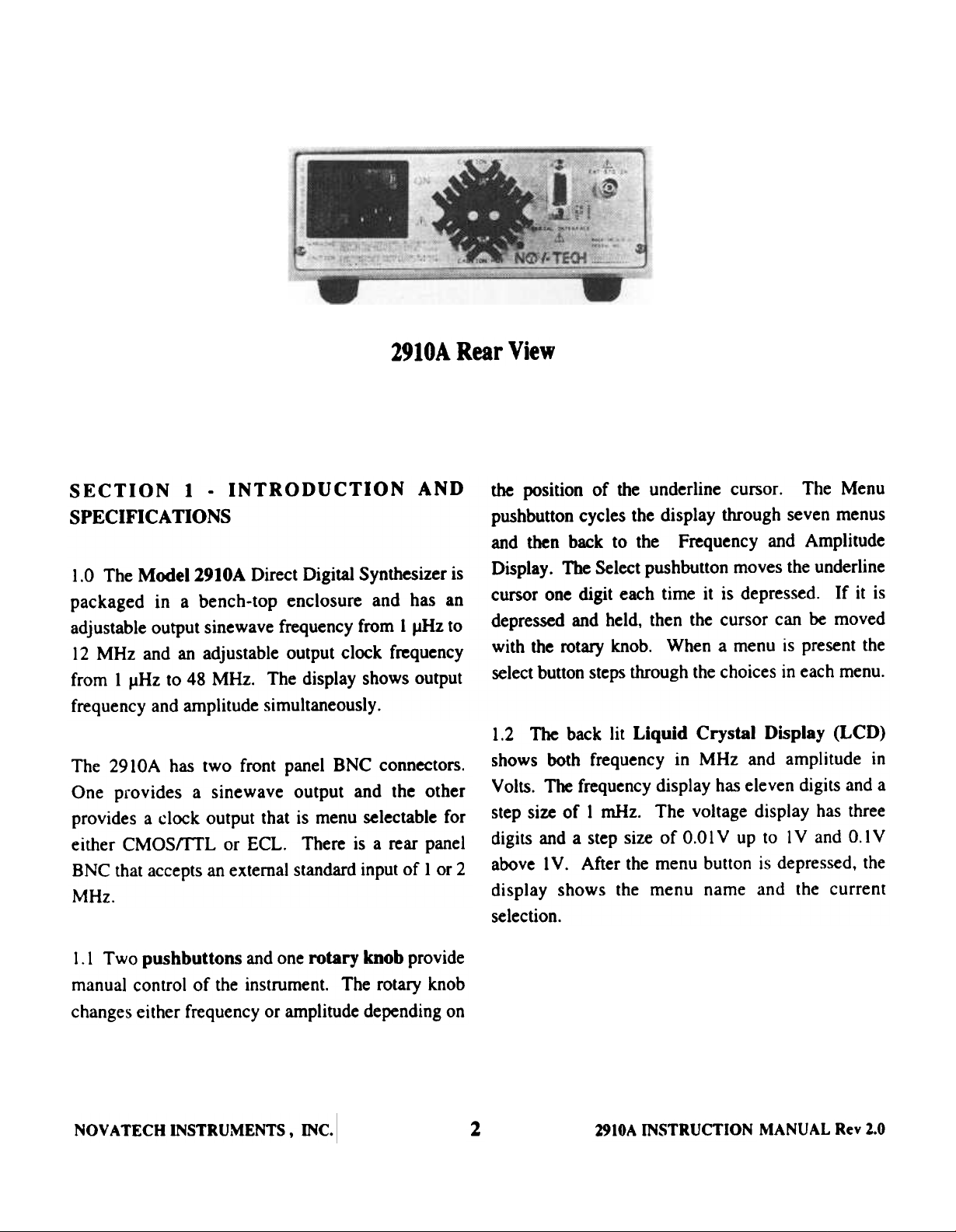
2910A Rear View
SECTION 1 - INTRODUCTION AND the position of the underline cursor. The Menu
SPECIFICATIONS pushbutton cycles the display through seven menus
and then back to the Frequency and Amplitude
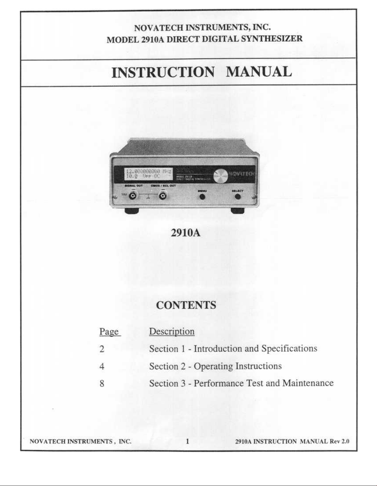
1.0 The Model 2910A Direct Digital Synthesizer is Display. The Select pushbutton moves the underline
packaged in a bench-top enclosure and bas an cursor one digit each time it is depressed. H it is
adjustable output sinewave frequency from 1 JJHz to depressed and held, then the cursor can be moved
12 MHz and an adjustable output clock frequency with the rotary knob. When a menu is present the
from 1 ~ to 48 MHz. The display shows output select button steps through the choices in each menu.
frequency and amplitude simultaneously.
1.2 The back lit Liquid Crystal Display (LCD)
The 2910A bas two front panel BNC connectors.
One provides a sine wave output and the other
provides a clock output that is menu selectable for
either CMOStrrL or ECL. There is a rear panel
BNC that accep~ an external standard input of 1 or 2
MHz.
shows both frequency in MHz and amplitude in
Volts. The frequency display has eleven digits and a
step size of 1 mHz. The voltage display has three
digits and a step size of 0.01 V up to 1 V and 0.1 V
above 1 V. After the menu button is depressed, the
display shows the menu name and the current
selection.
1.1 Two pushbuttons and one rotary knob provide
manual control of the instrument. The rotary knob
changes either frequency or amplitude depending on
NOV A TECH INSTRUMENTS, INC.
2 2910A INSTRUcriON
MANUAL R~1' 2.0
Page 3
1.3 Specifications 18
Output CM~ 08Ip8t
SINE: 0.001 Hz to 12 MHL CMOS output wiD drive CMosfm.. levels into loids >:JOO
11 Dilitl wbea set from front panel, lmlliest step 0.001 Hz. ohms. ECL output, wbeD termiDMed. il ECL IOK:: COIapeIibIe.
14 Dilitl wbeD set vi. EIA232, ImaUeIt I8ep 0.(XMm1 Hz. CMOS or BCL mode selected from display melaU (ft' compurer
iDIerfICe.
'rnXMOS/ECL: 0.001 Hz to 48 MHz.
II Digiti when set from front panel. smaJJeIt I8ep 0.001 Hz. Rile/FaU Time: <1~.
14 Dilitl when set via EIA232, KIn-llest step 0.~1 Hz. Ji~ <0.2.., of period or 200 pi wbidIever is ~
«I2MHz).
Output Amplitucle Jiner: d.., of period or 2ns ~ illJe*t: (> 12NRz).
SINE: 0.01 to 10 Vpp into open circuit (MIftbil_.1O ~),
Resolution is 0.01 V below IV, O. I V ~ IV. ~ I mV max AmpIitIKIe 1baI8ti~: < 2OCJI.
DC offset. Accuncy is :t IdB. Symmetry: ~ :t I~.
1i1XMOS/ECL: Fixed amplitUde, $O'IJ :t 10.., Duty Cydc. Setdu.11me
Meets 8PIX'..-jate level specification iDIo ~ circuit. Eo.. Frequency: <0.001'" in 100 ~ (setup delay exduded).
requires external termination to ECL levels. AmptibJde: <1" in 100 ms.
F;-~7 StabiHtJ Output I8pedaDa
10ppm, I year, 20-30 C. 50 Ohms:t 2.." female BNC tK)Cb Sipalud CMOSIBCL
If an extemal frequency standard is COIIIIecfed to the 291M Opea Emitter Ea. ~ requires tamiution to ECL levels.
external ~t then stability is equal to that of the eXtaDII BNC lbell is d8sil COIDIDOD.
stand.-d.
..,..,
Freq..-y Accur8CJ' Two ODe by sixteen cb8r8Cter blctJit liquid crystll display.
:t 5wm of displayed vaJue, 20-30 c. 24 tKMIrI. Frequcncy and ampObJde of siDe output displayed
Accuracy of 0.001 ppm is ~hievabJe.. simultaneously. Provides menu for insttument aecup IIId
,1
)
frequency standard. conb'ol.
Power k-.lSt8Dd8I'd
100, 120 tX' 230V AC:t I~, ~ 28V A Re8I' plDel BNC input KCepts either I or 2 MHz ~ 2ppn ~
- exterDal Itandard. Voltaps from 2ron V to 4: Vnas wiD
PbJ*8I lock and pull internal Rferela to eXterDaJ ItaIId8d.
2.6"H, 7 .3"W. 9.5"L, excluding bai1111d feet
5.21bs NOD.V_. MemOl'7
Last power-up state rer.ined in memory for 24 ~.
Pb8eNoile
<-110 dBc, 100 Hz Offsec. 10 Hz to 12 MHz 1IA231 c..pacer laterface
<- 9S dBc. 10 Hz Offset, 10 Hz to 12 MHz Rear panel RiDe pin female D-COImecttX' IeriaI iDput allows
setting aU ~ons. Baud Rate is POll'8llmabie ~ 300 to
S8ewaft Purity 9600 bIud from front panel malu. Once remote ~.- is
F~~ Harmonics SDiaimu selected, front panel display and COnb'ol we disabled.
.01-I~z <-6~c <-75dBc
.1-IMHz <-65d& <-7(ktBc OVENmClLLATOR
l-SMHz <-4SdBc <~ NOVA TECH INSTRUMENTS INC. Model 295OA s.i8I.
5-IOMHz <-3~c <-55dBc Quartz Frequency StaIM18rd is AvIiJible. COIIJIIIt~.
>lOMHz <-3<kmc <-35dBc
MeasInd ia a ftequency range exteadiDI to lOx test fJ8q.-cy.
P\Irity dep.de5 below I Hz. ~ - c "'
!
.~"'::
NOVA TECH INSTRUMENTS, 1Nc.
~
3
2910A INSTRUCTION MANUAL Rn 1..0
Page 4
SEC110N
2.0 latroducdon. This section of the manual
contains infonnation about connecting and ~rating
the 2910A and should be read completely before
using the ins~L
2 . OPERA 11NG IN~1
WARNING
NOTE
EitMr 5 x 2Omm or 1/4" x 11/4 .. fuses
WID)' H ue4 5 x 2(),u,a an NCDWlllleMe4
2.3 Local (FnJIIt PaaeI) OperatiolL The followiDl
procedure should be used to operate the 2910A
Direct Digital Synthesizer from the front panel.
This P'048Ct Is "08 4 t.'086h t..
groundila6 colld1leto, 0/ fA. pow., ,ourc..
B./o,. conn.ctln, Gn,thln6 to th.
1M"." , be sun to plII6 fA. pow'" cord
illto G P"'Pf'rl' wind pow,., nt"qlieGl t1I4Ils
COIIIImM to G hl6h tlUJIlitJ .nil f"HII'd. It is
.«.,rsGI'J to 6rQund lb. in.r~1It ill this
WGJ ia ord,., to GPoid ~l«trlcGl liock Gad
Gaun 118/. OJHr8tiD&
NOTE
The BNC OIItput shUld i.r ,~*d.
2.1 Input r~. lk 2910A is factory wiled to
operate from 100. 120 or 230 % 10'*' Volts AC. 60
Hz. Verify that the correct power is available before
plugging in the i~nt.
2.2 F1* RepI8CeI:;:~t. The 29 lOA is protected by
two It line input fuses that are located on the left
portion of the power receptical. Use a small
screwdriver to apply pressure at the side of the
fusebolder and the fusebolder will snap out.
a) C..=-::.~~ ~ 2910A to AC 1iDe JX)wef.
b) Connect the lpp11:Jpriate coaxial cables to the
BNC output COImeCtors on the 2910A front panel.
NOTE
1M output ampl;~ can vary from the output
uttiIIg whIII""illg long Cdble lengths IUIlu.r the
c4bl~ ;.f t.""i1l4t~d wit II 4 50 oil". load.
NOVA TECH reco".".~nd.f ""ing a 50 Oil".
Terminator. When u.fing a terminator the
display shows twice the ampli~ delivered to
tJlllood.
c) Turn 011 the 2910A by depessiDa the power
switch located on the rear panel just above the power
cord input pl. and wait approximately 7 seconds
while die 2910A performs . self test. The display
will read (c) 1993 NOVA TECH. 2910A Rev x.xx
during self test.
NOTE
WARNING
n~ 2910.4 ..",rt H dLrcoftft«/M fro. u..
pow~r b~/or~ att~mptill' to nplae~ t"~ /run.
CAUDON
For fire protection. replace the fuse's only with
slow fuse raled for 250 V and 0.25 Qnlpe'ns.
NO V A. TECH INSTR UMBNT5, INC.
tim~
1MJInt
with iu de/GIIlI s~gs of J.(XX) MHz and J.OO
Vpp DC aft,.r the self t,.st is completed. T1ae
defaldt mill.. .renings are shown in Table J. T1ae
29 J 0.4 ..,. Cml be chGnged using the ~ and
... 291OA
is used it will be setup
select PIU1I bIInMS. M~,." s~l«tioru 4. 5. and 6
affect the operatiora of the instrument and should
hI set appropriately prior to operating the
29 J 0.4 Wlr locGl cOfllrol.
2tltA INSTRUcnON
MANUAL an 1.8
Page 5
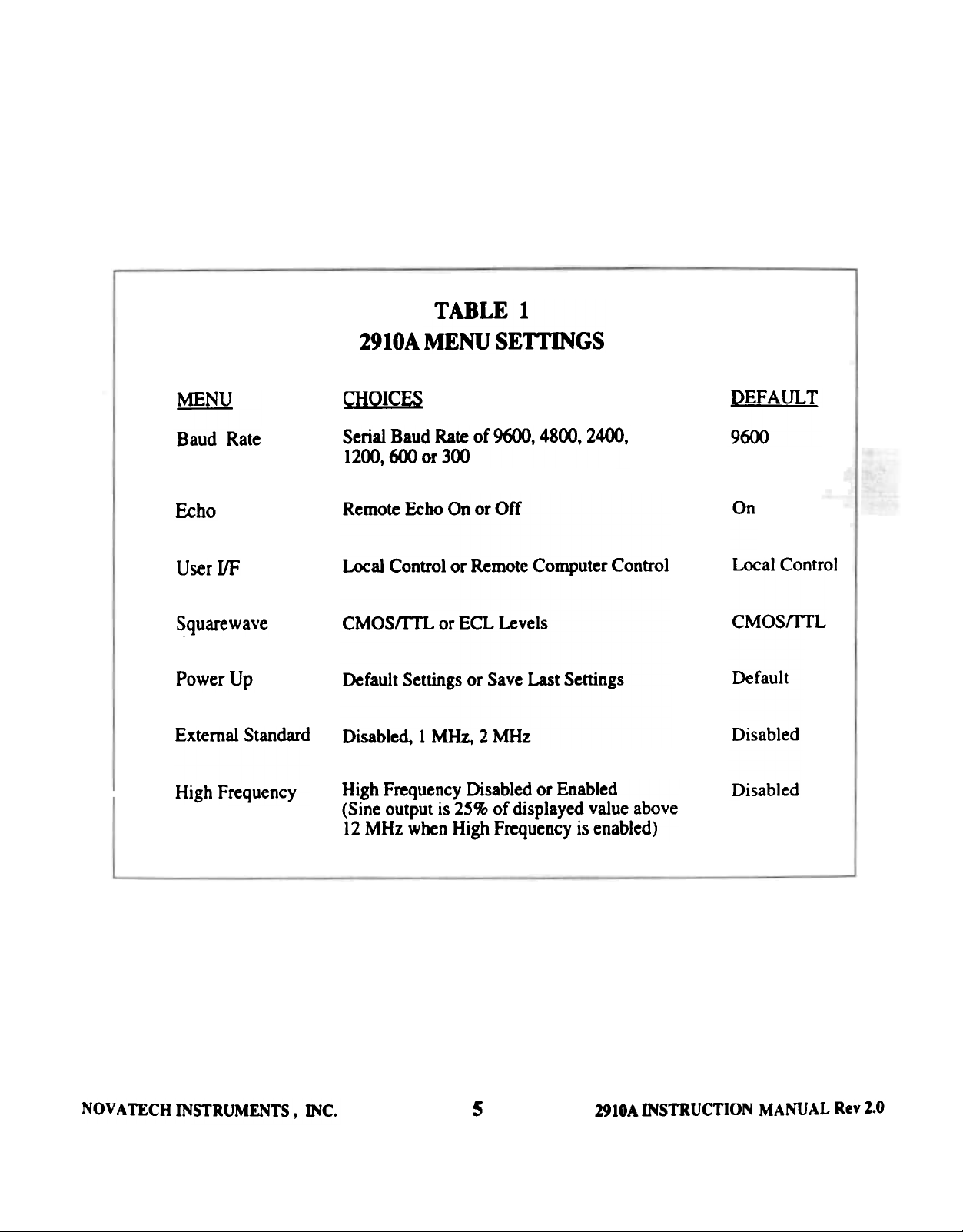
TABLE 1
MENU
B IUd Rate
f.dK)
UK( I/F
Square.ave
Powa'Up
ExternalStaDdlld
High Frequency
2910A
CHOICFS
Serial BIIM! Rate of ~. 4800. 2400.
1200. 600 01' 300
R8DmIe f.clX) OIl or Off
L«aI CcxIIIO1 or ~ C~ter Cootrol
CM~ CX' ECL Levels
Default Settin,s or Save Last Settings
Disabled, 1 MHz. 2 MHz
High FI'equefK:Y Disabled or Enabled
(Sine output is 2~~ of displayed value above
12 MHz when High freq~IK:Y is enabled)
MENU SE1TINGS
DEFAULT
9600
011
LocalCCXlbOl
CMOSrnL
Default
Disabled
Disabled
NOVA TECH INSTRUMENTS, INC.
~
5
Z910A
~ucnON
MANUAL Re9 2.1
Page 6
d) Push the menu button four times to recall the
Square Wave Levels menu. The first three menu
selections do nO( affect manual operation. Push the
select button to rccall "ECL" if you plan to connect
the square wave output to an ECL circuit. Leave the
selection on "CMOsrm.. " if you are not planning to
connect to an Eo.. circuit.
CAU110N
The ECL output is an open eminer output and
must be terminated to ECL leveu, nonnaUy 50
ohms to -2 Vor 510 ohms to -5.2. Selecting ECL
output mode while connected to a 1TL or CMOS
circuit nuly danulge the user's circuit, the 291OA
or both.
e) Push the menu button again to recall the Power
Up Mode Menu. Push the select button to display
the "Save Settings" selection if you want the 2910A
to save all current display and menu settings after the
power is turned off and then back on. Leave the
selection on "Use Defaults" if you prefer the default
settings shown in Table I to be set after the power is
turned off and then back 00.
f) Push the menu button again to recall the External
Standards Menu. Push the select button to display
either 1 MHz or 2 MHz if you plan to Jock the 2910A
to an external 1 MHz or 2 MHz frequency standard.
Leave the selection on Disabled if you do not plan to
lock the 2910A to an external standard.
g) Push the menu button again to display the High
Frequency menu. Push the select button and toggle
to display to either enabled and di5abled. When
enabled is selected the CMOS/ECL output can go to
48 MHz. However when in the enabled mode and
displaying over 12 MHz the sinewave output
frequency is 2S% of the displayed value.
NOTE
For optimum sinewave purity disable the High
Frequency mode when not needed.
h) Push the menu button again to recall the fiequency
and amplitude setting to the display. Set the desired
frequency and amplitude using the rotary knob and the
select button. The select button advances the underline
cursor and the knob changes the value. Pushing and
holding the select button enables the knob to move the
cursor in both directions.
NOTE
It ispo..fsible to adjust the contrast on the 2910A
display with a .fmaU insulated adjustment tooL An
acce..fS hole is located on the rear panel just above
the NOV ATECH logo.
2.4 Remote (Emmal Computer or Terminal)
Operatloa The following procedure should be used to
operate the 2910A Direct Digital Synthesizer from a
remote computer or temlinal.
a) Connect a cable between the 2910A and the serial
port of a computer or terminal. On most PCs COM 1:
is the serial port.
NOTE
The serial cable should be a straight through 9 pin
cable with a male common type connector on the
end that plugs into the 2910A. Only Rot. Tx and
GND are lUed.
b) Setup the computer or tern1ina1 so it uses 8 data bits.
I stop bit and no parity. Set the Baud rate on the
computer or tenninal at any desired rate between 300
Baud and 9600 Baud.
c) Perfonn the setup operations for Local Operation
as described in paragraphs 2.3 a) through g).
NOV A TECH INSTRUMENTS. 1Nc.
6
2910A INSTRUCTION MANUAL KeY 1.0
Page 7

NO V A TE CH INSTRUMENTS, INC.
~~
,
29tOA INSTRUcrJON MANUAL ReY 2.8
Page 8

d) Push the ~nu oonon until you have recalJed the
Echo Menu. Push the select button to toggle
between Ecl1O ON and &00 OFF as desired. EcOO
ON is DOI1Dally desirable wIleD UsiD, . dumb
tenninal, but is not commonly used with PC..
e) Push the ~U Ixmon again to recall the B8xi
Rate IMnu. Push the select button to select the
desirM Baud rate to match the computcr setup.
i) Transmit a command to the 2910A from a
computer or terminal to set the output amplitude of
the 2910A. The command .-a1d coosist of the
ASCD cb8I~ -A<SP>X.xx<CR>" where the
X's represent the desired numeric value of the
Amplitude in V 0115.
j) After receiving this ~~ the 2910A will
respond as described in paragraph 2.4 h) above.
f) Push the ~U txlnoa again to recall the Ula'
Interface ~nu. Push the select button to select
Remote. The 2910A is now ready to ~ift ~
c~~~~.
NOTE
1M 29 J OA Display and fronI ~l COIItroU an
di.rDbled wilen ill nIIIOtL 1M SELECT ~
r,.mains actiVl'. R,.mol,. Call be ",.l,.ct,.d or
unselecled only from 1M front panel.
b) Tra~~mit a commaod to the 2910A from a 2910A iR-pcmse I
b) Transmit a command
computer or terminal to set the output frequency of 2910A command.
the 2910A The command should consist of the
ASCD cbaracten -F <SP>XX.xxxxXXXXXXXX
<CR>" where the X's represent the frequency in
MegaHenz. <SP> is a spICe aod <CR> is . carriage
return. SECI10N3-PE
t) The 2910A letUp can be cban,ed using the ASCU
commands shown" in Table 2. Send these commands.
~ It a time. . desired.
1) The QBASICrM IXOII'Bm listing in Table 7 is an
example program that can be used to send commands
from a PC to the 2910A. It uses COM 1: aDd 1200
Bad, wbk:b rmy be chlDied by the user. It uks the
user to enter a 29.1 OA command. After the user
enters the command and hits the Eoter/Retum key.
the PC will transmit the command. display the
2910A response and again ask the user to enter a
SEcnON 3 . PERFORMANCE TFSf AND
--~--- - ---
After receiving this command. the 2910A will
respond by transmitting two chancters followed by
a <CR> <LF>. If the received command was
successfully inle~led and executed by the 2910A
then the two characters returned will be "OK". Iftbe
received commaod was not !I_~fu1ly received
and executed then the characters 8m8 will be
returned. The "N" represents an error code number.
See Table 2 for an interpretation of the error codes.
NOV A TECH INSTRUMENTS. 1Nc.
WARNING
To avoid p*rsoMl illjury do ,,01 r.,..ov. th.
pGMls or co.". and do JIot ope"'. Ii. 2910.4.
""I." tit. ptllI.ls alld co.." ar. properly
3.0 Introduction. The 2910A Frequency
Synthesizer requires no periodic calibration or
maintenance. It is recommended that the
.
2fllA INSTRUCrION MANUAL an 1.0
Page 9

- '-1c-" -: c - ~
,,' .
~ ~ ;': '. ~ -'. TABLE 3
RECOMMENDED TEST EQUIPMENT
Test Ins tnlment MInImum Soedftcatioas EIADInielDl trument
Digital Multimeter AC RMS, dB, 10MOhm imput impedance HP 34401A
4 1/2 digits, true RMS
RF Probe 100 kHz to 12 MHz, with known HP34301A, Fluke 85RF,
or calibrated response Tektronix P6420
Oscilloscope 100 MHz Tektronix T AS 465
Terminator 50 Ohm:t1 % Tektronix 011-0049-01
Frequency Standard 1 or 2 MHz, 0.2 V RMS to 4.0 V RMS Novatech Instruments 29SOA
Frequency Counter :t 1 ppm, 9 digits Tektronix CMC2.S lA,
.
Frequency Synthesizer Able to be set to 1 or 2 MHz:t 5 ppm Novatech Instruments 2910A
Lockable to external standard
HPS314A-OO1
Computer PC Compatible with QBASICfM and
tenninal emulation software
ECL Bias and Load 50 Ohm to -2.0V or 510 Ohm to -5.2V
Stop Watch
NOVA TECH INSTRUMENTS, 1Nc.
9
2910A INSTRUcnON MANUAL Rn 2.0
Page 10

performance test in paragraph 3.1 be perfonDed
periodically to verify that the instrument is
functioniq properly. If the insII\1-~ ckJes - ...
the performance test then it should be returned to
NOVA TECH IN STRU MENTS . IN c. fm repair CX'
NOTE
Unk.r" ut~m4l ~",.1IIaIiOft i.r .f"PP1i~d lor tile
ECL 0IItpIIt IU~ 1M CMOSl1TL output mode for
the M.xt 1e.JI.
replace~nt.
3.1 perf~1Ice T-. Refer to Table 3 for a
listing of the ~~nded test equipmcnt. If tile
~OIDmeuded test insttu~t is DOt available dM:I1 a
substitute that ~ts the minimum specifications
sJx)uId be used. The ambient temperature DISt be
betWeen 20 and 30 degrees C.
3.1.1 Front panel vertftcation (F~-~1)
a) COODect the 2910A Signal Out to . FI~,.
Counter, turn on power and let the ~nt WanD
up for 30 minutes.
b) Set the display to 1.00 MHz, 1.00 Vpp. The
Counter should read 1.<XXXXX> MHz % 5 Hz plus 01'
minus Coonter 8CCUrICY. Repeat ftX' die ~1Kies
in Table 4.
d)
Repelt
b) aDd c) 1m' the CM~1'Ea.
output
e) Select High Frequency Enabled aDd CM~
OUtIXIt.
f) Adjust OOtpIt to ~~ies shown in Table
Verify limits shown.
NOTE
Ira 1Iig1l fr,qu,ncy ,nabl,d mod, ,h,
CAlOSIECL 0fIIpMt fnqwncy u four time..
,hI SIGNAL OUTPUT frlqu,ncy for
frequency .lfiIIg.. aboVI12 MHz.
3.1.2 Front Panel Vertftcation (Amplitude)
a) Set the 00tp1t ~rx:y to 0.010 MHz IIKI ~
amplit\Mie to 10.0 Vw OC.
5.
NOTE
FnqllelU:Y cOIIIIter error add.r 10 dais test.
sure to acCOIIIIt for it.
c) Reset the 2910A to 1 MHz. Set the cursor to the
10 Hz position (S digits from the riaht). Adjust up
one count and down ~ count. Verify tbM the
counter registers :t 10 Hz shift. Verify that the
2910A display shows the conect frequency. Repeat
8.
for each value in Table 2.
NOVATECH
1NSTRUMEN'n
INC.
b) Usin,. sbcx1 BNC-BNC cable aDd BNC-toBanana ldaptor. connect the Signal Out on the
2910A to the DMM input. Select AC volts.
autorange on the DMM.
c) Verify that the RMS reading on the DMM is
between 3.104 V RMS and 3.967 V RMS with a
nominal vaI~ of 3.536 V RMS
d) Select the SfIIFT dB function 00 the DMM. The
display It.IId read 0 dB.
10
2910A UCrION MANUAL Rn U
INSTR
Page 11

TABLE 4
FREQUENCY VERIFICA'
2910A
SBmNO
LQ:B: HIGH
0.100
0.200
0.300 4~~-J'7 -'
0.500
1. (XX) 999995 .0
1. (XX)
2.(XX) 1,999.990.0 '
5.~ 4,999,97'.0'
O.(XX) 9.999,950.0
IO.cm
12.cm
99999.5 1<XXKX>.5
199999.0
11.999.940.0
CM~ ONL Y ABOVE 12 MHZ
-- COUNTER READING
ACTUAL
2(XXX)1.0
5CXXm.5
1,(0),005.0
2.(0),010.0
, ,CXM»,025.o
1 0,(0),0.10.0
12.CXM»,060.0
1.5.(xx)
20. (XX)
2.5.(xx)
3O.(xx)
3.5.(xx)
4O.(xx)
48 . (XX)
NOVA TECH INSTRUMENTS, INC.
14.999.925.0 1.1.(XX).07.1.0
19,999,900.0 2O.(XX),l00.0
24.999.875.0 ~.(MX).1~.0
29.999 .8!().0 3O.(MX).150.0
34,999,82.5.0 35,(XX),17.1.0
39,999,800.0 4OJXX).2(X).o
.7,999,760.0 48,(XX),240.0
11
291M INSTRUcnON
MANUALReYU
Page 12

e) Select the amplitude values in Table 6. Verify
that the DMM readings are within the error limits
1iM)wn. This verifies the 8UeOuat(X'.
f) Di.ICOII~ die cable from the DMM. COImeCt
the RF probe to the 2910A SianaI Out usina a probe
tip to B NC ldal*r. ConDeCt the RF pobe to the
DMM. Select DC volts, autorange.
NOTE
1M ECL wriJicatiora t~st requires an ~xt~mal
IoGd 48Id power 11Ippiy. q YOM do IIOt ~ ECL it
can 1M IJPlOred.
1) Select tile ECL mode in ~ ~nu. ConDeCt tile
IOId . -.n in T Ible S.
g) Set the 2910A to tOO MHz, 10 Vw OC ~
Wait for a settled DMM reading. then select SHIFT
~
"-
'~ ~
TABLES
dB 1rxxIe. The display sbcx1Id read 0 dB.
.VTERM LOADR
b) Adjust the freq~OCY in I MHz Iteps to 12 MHz.
Verify that the DMM displays between -ldB aDd
C~.::I.. -2 VDC 50 Obms
O{mtn'
+ I dB for all settinp.
-5.2VDC 5100llD8
NOTE
~ frequency relpOlaSe .rror of 11M probe GddI
to this test. Be ". 10 GCCOMt for It.
"*= BNC IbeII is ;-I~_-;:-V--:;P-.,
i) Reset the 291OA ifeq~." to 1 MHz. Cb8F" m) Verify ECL OUqxIt levels (nomin
amplitude to 0.79 Vpp OC. Reselect SHIFf dB to -1.6 low).
rezero the DMM. Repeat b) fCX' this letting.
n) RepeUIteps t) through m) after selecting High
j ) DiSCCX1nect the
2910A.
DMM aDd
tbeprobe
fromtbe
Frequency enabled in the menu. Highest test
~ueIM:y is BOW 48 MHz.
ally -0.8 bi~
k) Select CMOSIrn.IJMxIe in the DalU. Verify,
using the oscilloscope with a xl 0 probe that the
CMOSIECL oot sipaJ swiDIS from 0.4 low to 4.8 V
high with less than I volt overshoot, undershoot 01'
ringing. Verify sy~ of ~ to fAY~. Set
the 2910A to the fJequencles of b) fOl'this tesl
NOVA TECH INSTRUMENTS, INC.
0) DiscODMCt all cableS. Reset instrument to
CMOSIrrL. High Frequency disabled. 1.00 MHz.
10.0 Vw.
p} COIIDa:t 0UtpIt to oscilloscope throogh a T~
BNC. Observe amplitude. Connect SO Ohm
terminator. Amplitude should decrease to 1/2
previous.
12
1918A IN~UcnON
MANUAL an 2.8
Page 13

AMPLITUDE VERIFICA nON _e
2910A DMM READING (dB) Sti"I-I"JNG
VDD oc ~ BI.GB ACnJAL
TABLE 6
10.0 -0.01 +0.01 .;
7.9 -3.047 -1.047 c ;~;
, ~ '
6.3 -~.013 -3.013 ~~'.: .~~I'~~~.~~~
0 _7 021 _c 021 ;,'~ " c - ~
~
J. . J. .,- ~
2.5 -13.041 -11.041 ; ---!
16 16918 14918 ~e.'~""
. - . - . :~ .;-- I I_~:' :"r~~~' ;
[,
, c
063 ~. ,",c O13 23013 5 :::.~. .:~"'; i~ (,
. -1..1. - . ~ ,~ ~~~ i :'~~lr: '" _2}
, ., . ccJJL ~,
0.2.5 ~ -33.041 -31.041 ~c-:'-_. -!~-"..~~:~~~,'~
010 -41 (KX) -39 (XX) . ~_.~- ~-- - -~~' -~;.'--:"c~ '
. . . ;,,'
0.05 -47.021 -4~.021 I~.; :-
0.02 -54.979 -S2.979
0.01 -61.<m -59j;a)c .~. =--'--
q) Disconnect oscilloscope and connect a DMM to 3.1.3 External Standard Verification
Signal <All Select DC volts, autorange. Verify a DC
value between -1 mY and +1 mV.
NOTE
Some DMMs do not have adequate high
frequency filtering for Low Level DC
measurements in the presence of high frequency
sinewaves. If you are not using the
recommended meter you will need to check YO'"
DMM.
a) CoJmect either a 1 MHz or 2 MHz frequency
standard to die EXT STD IN on the rear of the
29l0A. through a BNC tee connector. Select
External Standard Menu for 1 MHz or 2 MHz to
match your input
b) Settheou~ofd1e2910Ato1O~ 1 VWOC.
c) Connect the 2910A signal output to one channel
of the oscilloscope. Connect the External Standard
~ :::"J
NOVA TECH INSTRUMENTS t INc.
13
2910A
INSTRUcrJON
MANUAL ReY 1.0
Page 14

from the tee to the other cbal!
Set up the oscillosc. to ,
stalxiard with ~ximllely
signal on the screen.
channel of the 0Ici1I~.
to milei' ~ die: extaDIl
ilely ~ cycle of tile 2910A
d) Connect the output of the first 2910A and the
UUT to an oscilloscope as described in 3.1.3
paraarapbs a) aDd c). TriIFr from the fIrSt 2910A
Sipal wt. Adjust the UUT for 1.00 MHz OUtplt aDd
10 VppOC.
d) Verify using the stop witch d]AC b 2910A 0UtpIt
sianat taka greater than 100 seccxMIs to drift ~ e) Adjust the 1 Hz position of the fmt 2910A while
complete cycle. observing the oscilloscope. The signals should
remain locked with DO drift between 0.999998 MHz
NOTE: and 1.(XXXK)2 MHz minimum (typically tWice this
nnae ).
This is a galno- go test. 1M drtI 8A.ld N
u..,.rc~~.
f) Rq)e" c) bouah e) with the first 291 0 A 8M! the
UUT let to 2.0 MHz. The lock range sfX)uld DOW be
e) Adjust the 2910A frequency to 1O.(xxxxx)1 MHz 1.999996 to 2.(XXXX)4 minimum.
aDd 9.9999999 MHz. The drift should now take 10
seconds in ech case. (F"1nt left; tbeII riIbt). g) Adjust the amplitude of the first 2910A fnxD 1
VppOC" to M) VppOC". The UUT IIXM1ld stay ~..,krd
f) If the ampHtude of your 118nd8d is -tiustabJe. with impec~ptible drift. lanore phase shift and
repeat d) for amplinldes of 200 mV RMS (S6S ~tary pbasejumps.
mVpp) to 4.0 V RMS (11.3 Vpp)
3.1.5 Battery Backup Veriftcatlon
3.1.4 External Standard Verlftcatlon (Alternate
method)
a) This metbcxl allows testing of die kJet ranae. ~
requi~s a known good synt~~ locked to an
extemal standard. This desaiptiCXI ~ the use
of another 291 GA.
The charge .rtate of th~ i1ltemal ban~ry i.r
~11ol1ed dIIrlIIg nord'~ and .rhipmellL nu
ten IfUI.rt be perfomled aft~r die in.rtnllM1Jt ha.r
be", powered for at lean 120 hours.
NOTE
b) Connect the external standard to . kIKJwD aoocI
29 lOA and select d:Ie appropriate ExtaDal StalMlard
McxIe (I or 2 MHz). Adjust this 2910A for 1.00
MHz lad S V ppOC.
c) ~ the Signal ~ ofllle locked 2910A to
tbe 2910A under test (UUT) EXT STD input
c~ . Select the 1 MHz extanal !tL~rd mode
on the uur.
NOV A TECH INSTRUMENTS ~ 1Nc.
a) Select Save Settings mode in the menu.
b) Set the fJequency and amplitude to something
other than the default values of 1 MHz and 1 V.
Record y~ settings. Turn oft' power.
c) After 24 boon restore JX)wer. The display values
should be the ~ as those recorded in b). Verify
that the 0UtPJts match the displayed val~.
14
INSTRUCTION
2910A
MANUAL an 1.0
Page 15

d) Verify that all menu seUinp selected before
power down have maintained tbriir ~~.
through 3. t.4 using a
emu1atiCXl program on a
operating instructions
connection instnlCtioas.
terminal or a tenninal
complier. Refer to the
for the command and
3.1.6 Front Panel Menu Vertftcatton.
a) Verify that all the menu items shown in the
ope~DI ~ODS sectiOD are selectable.
b) Depress tile SELECT pusblxlttoo aDd iM)Id down.
Verify tb8I tile IU8y bob iOO\'eS tile cunor ~ for
CW aDd left for CCW rotations.
3.1.7 Computer Interface Verlftcation
a) ~ ux.t ~Iete ~dXXI to verify tile COIDpIter
interface is to ~ the verification tests of 3.1.1
TABLE 7 ~ ~;r
QBASICTM EXAMPLE PROGRAM -
NOTE
1M eXDIrIple QBASICN pm""", ill Taw. 7 i.r
writtm for this pIU'pO#. Y DIlllid)' al.ro KJC Q
temainal em..lati~ program IIICh as
PROCOMM"W.
b) The followinl QBASICrM proJrlm enables
you to g:::-Vi~mk:ate with the NOV A TECH 29 lOA
Syn~~. Prim' to nmning the program make
~ that the 2910A User Interf~e Menu h8S Echo
set to Off, the Bald Rate let to 1200 aIKt ReIIX*
set to OIL It is also ~ tbIt yoo lie
COIL~ to COM I :. Hold down the Control by
and bit the Break by to exit the program and
retum to QBASICN.
., ~~ !-}.";. ;;
- ..
. , " .
" .
. ,
CLS<CR>
OPIR 8COM!: 1200, N, 8, 1, CDO, CSO, DSO, OPO, RS 8 FOR RANDOM AS 11<CR>
PRIR'!' 11, 8 8 <CR>
LIRE INPUT Il,a$<CR>
00 WHILE lsl<CR>
INPUT 8;atrBR CCIIMAND TO SEND TO ~910A: 8, CMND$<CR>
PRINT Il,CIam$<CR>
LINE INPtn' 11, RESP$<CR>
PRINT RBSP$<CR> .'~f'"' -
LOOP<CR> r. : ~~-~;;.
aD<CR>
.. ",.'
, . " ..
P«)V A i8Cii HTR1J..-1S, -=- 15 81tA ~1CrIC:.f MAMJAL'" 2.1
~
~
~~~
Page 16

WARRA NTY
NOVA TECH INSTRUMENTS, INC. warrmts that all ins~ it m8Duf~ are
free from defects in material and workmanship and asrees to replKe or repair any
iDSUUllXDt foolKi defectiw durinl a perioo of ~ year from d8e ofl~ at to oriaiDal
purchaser.
This WllTanty is limited to replKiDg CX' ~s-iring defective instruments that have been
~tumed by owner, at owner's cxpeose, to NOV ATECH INSTRUMENTS, INC. and that
have not been subjected to miIUIe, .~ imp;~ !!!Jta1l~ repair alteration or
accident. NOV A TECH INSTRUMENTS. INC. shall have the sole rilht to final
determiD8tioo ~galdiDl b e~j~~ IIMI Calle of . defect.
This warranty is in lieu of any ~ WarnDty, either expelled or implied, includiDI 00t
DOt limited to any warranty of ~bantlbility or fitDess for a particular purpose. In DO
event shall seller be liable fcw collllCral CX' COOIcq~tiaI d8mal~. Some lilies 00 0«
allow limitations or exclusion of conseq~ntial damaaes so this limitation may not apply
to yoo.
All ins~ts manufactUred by NOV A TECH INSTRUMENTS. INC. IbouJd be
inspected as soon as they are received by the purchaser. If an insttument is damaged in
shiplr£nt b pucbuer sIMXIId iiiJDw:.~1y file a claim with b ul82SlKil-tII;i(XI company.
Any mstnlment returned to NOV A TECH INSTRUMENTS, INC. should be shipped in
it's origiDal shippina cootaiDer (X' other rigid COD~~ and ~ted with adequate
shock absorbina material.
This warranty constitutes the full understandinl between NOVA TECH
INSTRUMENTS. INC. w the PJrCbuer aDd DO ~...nt extendinl or modifying it
will be biDdiDJ oa NOVA TECH INSTRUMENTS. INC. !!!!-~ m8de in writiq and
signed by an authorized official of NOV A TECH INSTRUMENTS. INC.
NOVA TECH INSTRUMENTS, INC.
2~.301.8986,ntsales@eskimo.~ Fax 206.363.4367
COPYRlOIrr 1994 NOVA'
NOVA TECH INSTRUMENTS. INC.
17962 Midvale Avenue N", Suite 219
Seattle, W A 98133 USA
http://www.
,eskimo.com/-ntsales
INSTRUMENTS. INC.
16
2910A
INSTRUCTION MANUAL a.. 1.8
~
Page 17

2910A/O2 DIRECf DIGITAL ~HM3IZER
ADDENDUM TO MANUAL
The Model 2910A/02 is a ~~ wnioa oflbe McxIel
~ Model 2910A manual
applies to dJe 2910A/02 wid! die foUowina changes:
SEcnON 1: INTRODUCTION AND SPECIFICA nONS
The M~l 2910M)2 ouq,Uta haw been m~4 to provide dual differential clock ~ frgn
10Hz to 24MB%. ~ 2910M)']. bas two front ~ Trlax ~ (Trompeter BJ.7 6 or
equivalent) both provi~ different dc:x:t 0UtpIts from RS422 drivers. AD feabD'es IeJadng to
ampHtixle aDd output ~ eJectim ba~ been ~Hm1nated. A provision to disable die front ~
control has been ""~
Delete ref~ to ampH~ ~ve aDd CMWm or Ea... Clange frequency l3DJe to
10Hz to 24.0MHz. Clan. output deacriptim to read: Dual, differential clock ou~ usiD&
DS8921AN RS422 ~la:eivers. OutpUts are offset positi\'e from ground. DeJete re~ to 50
omn ootput impedaDce. ClInIC OuIput ComJa:tm ref~ to mad TRIAX ~tor. Trompeter
81-76 or equivaJent Change extemaI standards to SMHz or lOMHz.
SECTION 2: OPERA TING INSTRUCTIONS
CAU110N
The Triax output shield is arounded, whDe the two iDDer comuctors are offset from
the JI'OUDd. ShoniDl eidJer CB' both of b iDner coIMIUCIm'S coodnoously to ground
or toJetber can result in dam. to die drivers or the 29 I OM>2.
Ignore aD ref~ to AmpIinxte aDd to CMQS/'I11.. CX' Eo... The Square Waw and High
Freq1leDCy cboic:es have been ~ from the ~US and frmn the oomputer I/F C(XDmAftd. The
extemal Standard menu DOW seIecIS SMHz or 10MHz. The SerialIlF COiUIeC'"IDr (XI the rear ~
bas been modified to .:ce.. a switch CX' CODtXt closure to digb~ control of the iDsInJIDenL Pin 8
is contact common (COlnected to iDlttUment gr~) and Pin 9 is pulJed-Up to +SV dlrougb lOt
ohms. A switch clC8ure « 500 ohms) wD1 disable die conanl of the insttument aDd wiD be
ind-.~~-rl on die secmd line of the display showiDI ~ttOI ~..-Ned "
Page 18

CAImON
PIN 9 of the Serial ~~ must not have any voltaJe5 applied.
is being used. verify that pin 9 is dilCooDeCted from die It;ria1 cable.
NOTE
It is ~].iDmended tbIt ex1rm8l ~---~ DiICbIIp (ESD) JX'OcecdOD be
provided of Pin 9 of the r.-:m:~ if switch ~]e is \lied. 1bIs pin does not have
the same intemal ~dCXI u dJe aial p«t. It is iDleD~ only fcr systems
applications.
SECTION 3: PERFORMANCE r~
Ignore all refel'eDces to ampJitt*. CMOsmL. BC.. and Hi&h ~~ Table 4 can be used
for flequeDcies below 24MHz. 1k same ~.cies apply. Ex~ lfaIxI~td \lerificaooa is
performed u oudiDed exCept 5MHz uKll 0MHz stIDd.. 8e ~~~ f(X' lMHz aDd 2MHz.
To verfy the differential output ~orm die f'oDowiDa.
a) Verify IIDgie-eDded perfOrmaDce. CoDllCct a lOx -=ope probe to the test
oscilloscope. Verify that both inner cond1x:tOlS of boch Triax 0U1puts swing from a
minimum of 0.8 Vol~ to 2.4 Volts. U~ the frequellCiea ofTabJe 4 below 24MHz for this
If the serial
port
telL
b) Verify dJrrerential performance.
NOTE
This test requiJes a TIiIx cable to BNC and an ~m,*. capable ofdiJlelellIial
Connect dJe 2910A/02 0UqJUt to an C&:iJloscope set frx differential ~.UJl!em.en1S.
Verify that the outpm swinp a mln1mum off: 1.6 Volas ovu die irequelx:ies of a)
above, when lermiDat~ with 100 ohms. Verify dIat die DC offset is less dIaD 0.4
Volts.
~"-.;~
.:. ;.
.
"t-
~
 Loading...