

Page 1
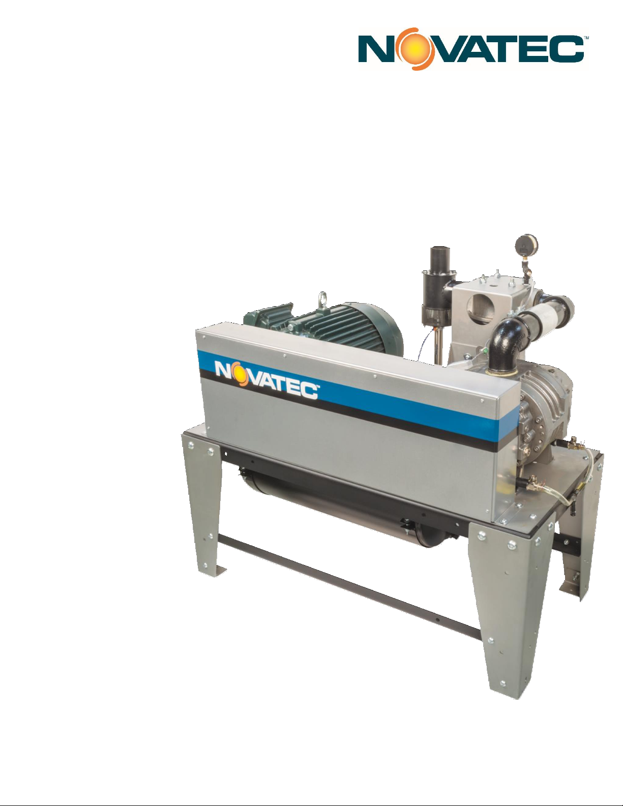
USER GUIDE
VPDB
Vacuum Pumps
MODELS:
>VPDB-3
>VPDB-5
>VPDB-7.5
>VPDB-10
>VPDB-10/3
>VPDB-15
>VPDB-20
VPDB-UG 01 April 2019
©2019 NOVATEC, Inc. All Rights Reserved
Page 2

User Manual: VPDB-UG 01 April 2019
Serial Number(s):
Model Numbers:
In the space provided below you should record the model and
serial number(s) of your equipment and the date the equipment
was received.
In the event you would need aftermarket assistance our parts and
ser- vice department uses this information, along with the manual
number, to provide help for the specific equipment installed.
Please keep this instruction manual, any relevant addendums,
engineer- ing prints and parts lists together for accurate
documentation of your equipment.
NOTES
DISCLAIMER: NOVATEC, Inc., shall not be liable for errors in this
instruction manual. Information can change without notice. Novatec
makes no warranty of any kind concerning the information contained
herein, including, but not limited to the implied warranties of
merchantability and fitness for a particular purpose.
©2019 NOVATEC, Inc. All Rights Reserved.
Page 3

Table of Contents
1.0 INTRODUCTION ............................................................................................................. 4
2.0 WARNING ........................................................................................................................ 4
3.0 OPERATING LIMITATIONS…………………………………………………………………………….4
3.1 Operating At Higher Altitudes ………………………………………………………………4
3.2 Seek Time …………………………………………………………………………………………….4
4.0 UNPACKING ………………………………………………………………………………………………4
5.0 GENERAL INSPECTION ………………………………………………………………………………4
6.0 MECHANICAL INSTALLATION …………………………………………………………………..5
6.2 Regulator Warning ……………………………………………………………………………….5
6.3 Combination Vacuum Breaker and Vacuum Relief Valve ……………………….5
6.1 Compressed Air Supply …………………………………………………………………………5
6.4 Discharge Selection Valve (DSV) …………………………………………………………..5
6.5 Closed Loop Relief Vent (CLR) ……………………………………………………………….5
6.6 Closed Loop Dry Air Vacuum System ……………………………………………………..6
6.7 Ambient Air Vacuum Conveying System ………………………………………………..6
7.0 INSTALLATION …………………………………………………………………………………………….7
7.1 3-Phase Electrical Power ………………………………………………………………………7
7.2 FLA / KVA Listings ………………………………………………………………………………..7
8.0 STANDARD SPECIFICATIONS ……………………………………………………………………8
10.0 PARTS LIST ………………………………………………………………………………………………8
11.0 MAINTENANCE AND INSPECTION SCHEDULE ……………………………………….9
11.1 Belt Adjustment and Replacement ………………………………………………………9
11.1.1 Inspecting V- Belts …………………………………………………………………………..9
11.1.2 Replacing V Belts …………………………………………………………………………...10
11.2 Special Note: Sheave Re-installation …………………………………………………10
11.3 Cleaning Air-Filter …………………………………………………………………………….10
11.4 Removing Sound Curtains …………………………………………………………………10
11.5 Blower Lubrication …………………………………………………………………………..11
12.0 WARRANTY ……………………………………………………………………………………………12
Page 4

4
1.0 INTRODUCTION
NOVATEC VPDB Series Vacuum Pumps are designed to
pneumatically convey plastic pellets or powders in a
vacuum conveying system. It does this by creating a
vacuum to “pull” air through the piping system. Plastic
pellets or powders are introduced into the moving air
stream in various ways, including through the use of
probes, pick-up tubes, and rotary air locks. The VPDB is
used in conjunction with vacuum chamber station valves,
etc. to form the conveying system, which is controlled
with either Master Control or Distributed Control Panels.
Several vacuum power units may be designed into the
system as required. Vacuum conveying systems typically
distribute material from silos, surge bins, blenders, or
drying hoppers to processing machinery.
2.0 WARNING
Always disconnect power before servicing. Only qualified
technicians should service, maintain, or repair the VPDB.
Before using this equipment, read in detail the product
bulletins and other information found in this manual.
A safe installation is necessary before operating the
equipment. The instructions should be understood and
followed before installing or operating the equipment.
3.0 OPERATING LIMITATIONS
3.1 Operating At Higher Altitudes—
3000 ft above sea level or more.
Atmospheric pressure is lower at higher elevations, and
as a result, the compression of air by the pump requires
more work for vacuum conveying. In these higher
altitude applications, the pressure relief valve of VPDB
pumps must be adjusted on site to prevent the pump
from damaging itself or the motor by attempting to compress air of reduced density to an unsafe level. Contact
Novatec Engineering or Service at the number on the
front cover of this manual when operating the pump at
3000 ft or higher elevation.
Blower exhaust temperature and motor cooling are a
function of both vacuum level and elevation. Blower
exhaust temperature must not exceed 300°F to avoid
premature blower failure.
Decreased motor FLA limits may require alternate overload protection or increased frame size/Hp.
3.2 Seek Time
Excessive starting and stopping of the pump will reduce
blower and motor life and void the warranty. Seek Time is a
control parameter that allows your pump to operate for short
periods in vacuum break mode (no vacuum loading) while the
system control searches for new demands.
Using the Seek Time feature, pump starts must be limited
to 12 per hour to prevent premature failure. The
minimum Seek Time for a pump is 180 seconds to
prevent exceeding 12 starts per hour. Optimum Seek
Time may be set dependent upon pump capacity,
utilization, number of stations, capacity of each vacuum
chamber, and individual station throughputs. (See your
control panel instruction manual for information on Seek
Time)
4.0 UNPACKING
Caution should be exercised to see that the equipment is
not handled roughly. The crate must be removed
carefully. The machine must not be used to pry against
Do not pry against the machine when removing the
crate. The vacuum power unit is usually shipped
completely assembled and requires no further attention
prior to installation. Note any shipping damage on
delivery receipt and report immediately to trucking
company.
5.0 GENERAL INSPECTION
When the unit is unpacked, make a visual inspection
looking for missing parts or damage that may have
occurred during shipment. Report any missing parts
to Novatec immediately. All electrical and mechanical
connections should be checked for tightness, as vibration
during transit may cause them to loosen.
IMPORTANT: Before placing the vacuum pump into
service, be sure oil has been put in the pump, as oil may
have been drained following factory quality control testing. See page 11 for lubrication guidelines.
Note that replacement blowers are shipped without oil.
Page 5
5
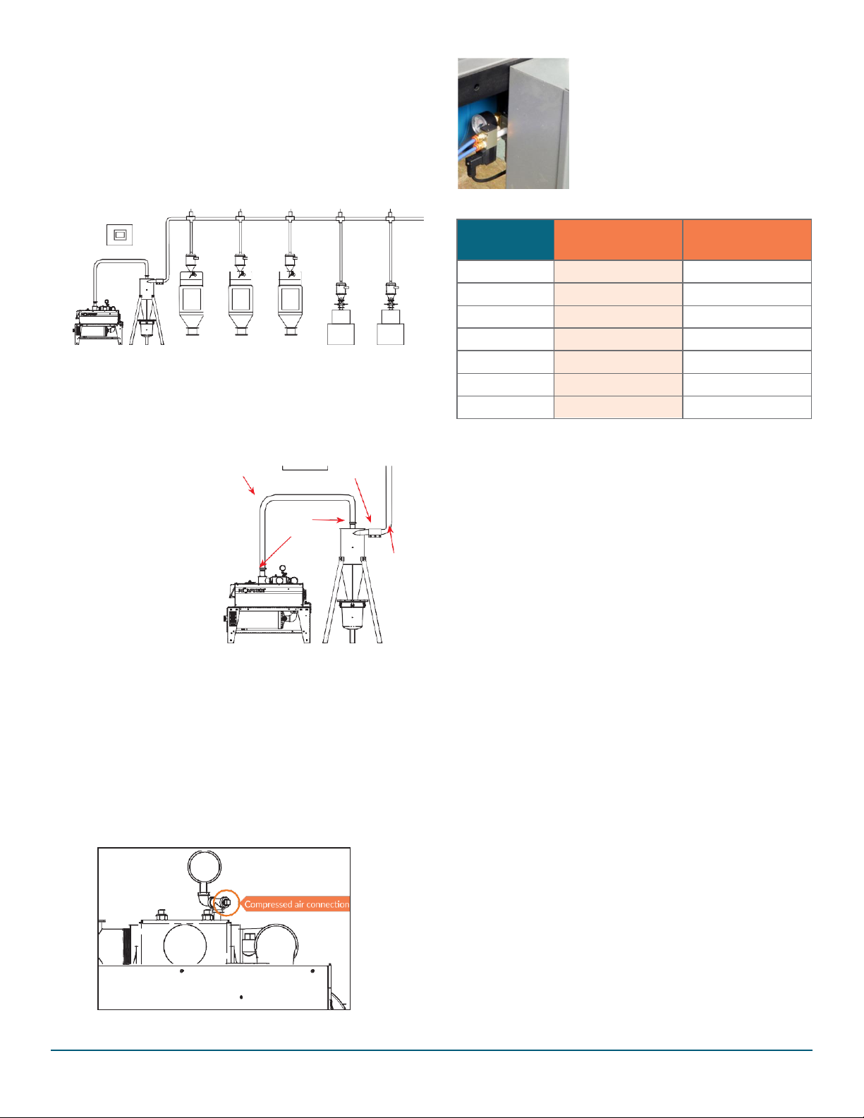
6.0 MECHANICAL INSTALLATION
Only qualified technicians familiar with local and national
codes should install this equipment. Connect the vacuum
lines as shown on the installation drawings. Connect the
compressed air (80 - 120 psig) to air actuated valves as
required.
Locate the pump where it can be interconnected with the
vacuum system piping easily.
Control
6.2 Regulator Warning
The compressed air regulator has
been set at the factory to allow the
vacuum breaker to relieve at the
specified vacuum. Tampering with the
regulator will void the warranty. Only
qualified Novatec service personnel
may adjust the relief point via regulator pressure.
Vacuum
Receivers
Cyclone
VR-MM
(Machine
Mount)
Receivers
Vacuum Pump
Hoppers
Process Machines
Accommodations should be made to allow full access of
the pump for service, especially the belt guard, starter,
filter, vacuum breaker valve, vacuum blower and vacuum
relief valve. The vacuum gauge should be visible, but can
be carefully rotated in its fitting as required. The pump
6.3 Combination Vacuum Breaker and Vacuum Relief Valve
should be secured to
the floor to prevent
movement from vibration and isolating pads
(not supplied) may be installed to minimize noise
transfer to the floor, if
desired.
The pump is commonly
located near the vacuum conveying sys-
Rigid Tubing or
Flexible Hose
Hose
Clamps
3-Bolt
Coupler
Rigid
Tubing
The Novatec vacuum breaker valve for system seek
operation also serves as the vacuum relief valve to
regulate the pump’s workload. The dual functionality is
accomplished by utilizing an equilibrium of compressed
air pressure and vacuum level in conjunction with the
vacuum breaker action, governed by the system’s
conveying control panel.
NOTE: Specifications will be reduced for standard pump
assemblies running on 50Hz. Information shown is for
standard VPDB vacuum pumps. Refer to special job
tem’s cyclone dust collector and is commonly connected
directly to the cyclone lid with rigid tubing or flex hose. It
is convenient to service the dust collector and the pump
filter at the same time.
6.1 Compressed Air Supply
Clean compressed air should be supplied to the VPDB
pump’s vacuum breaker valve regulator, providing 80 to
120 psig. A filter (not supplied) should be provided if the
cleanliness of the air is questionable.
drawings for custom unit information if applicable.
6.4 Discharge Selection Valve (DSV)
Pump exhausts to atmosphere or can be pipe outside of
pump room.
• Requires a separate Relief Vent in a closed system.
• Includes 3-Bolt Coupler and pump adapter fitting.
• For use with either VRB or VPDB pumps.
6.5 Closed Loop Relief Vent (CLR)
Provides Pressure Relief in a Closed Loop Conveying
System.
• Install near take-off devices in a closed loop system.
• Install one per row of take-offs that share a common
closed loop manifold.
Pump Model
Relief Point for
60hz Operation
Regulator Setting
VPDB-3
12.0”Hg
29 psig
VPDB-5
12.5”Hg
30 psig
VPDB-7.5
12.5”Hg
30 psig
VPDB-10
12.5”Hg
30 psig
VPDB-10/3
12.5”Hg
30 psig
VPDB-15
12.5”Hg
30 psig
VPDB-20
12.5”Hg
30 psig
Page 6

6
6.6 Closed Loop Dry Air Vacuum System
6.7 Ambient Air Vacuum Conveying System
Machine mount vacuum receivers
Machine mount vacuum receivers
Material
selection device
Ambient air passes through
vacuum purge valve and
conveys material.
QSM
(Material selection station)
Dry air passes through vacuum purge
valves and conveys material.
CLR
(Closed-loop relief valve)
Closed-loop air from
vacuum pump exhaust
DSV
(Discharge selection valve)
Page 7
7
7.0 ELECTRICAL INSTALLATION
Connect the proper power supply (check nameplate)
through a main line disconnect switch (not supplied)
to terminal connections L1, L2, L3 and ground into the
VPDB control cabinet that contains the motor starter.
This is the only power connection required since the
motor is pre-wired at the factory. See schematics with
this package. See FLA specification table below.
Connect control wiring from the conveying system
control panel, to the same electrical enclosure as shown
on the wiring schematic for the conveying system control
panel. Verify the correct rotation of the motor with the
directional labels on the pump assembly
7.1 3-Phase Electrical Power
1. Verify nameplate information on the pump frame
assembly.
2. Use the FLA/KVA chart below as a guide
3. A nominally rated 3-phase disconnect switch must
be provided.
4. All connections must be provided in strict adherence to
local and national codes by a qualified electrician.
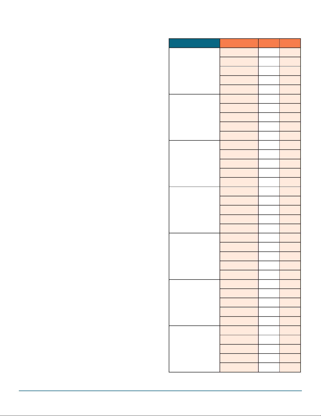
7.2 FLA / KVA Listings
Full Load Amperage and KVA ratings for VPDB vacuum
pumps by model and voltage:
Horse Power
Voltage
FLA
KVA
VPDB-3
3HP
208/3/60
9.4
3.5
230/3/60
8.5
3.5
400/3/50
5.2
3.5
460/3/60
4.3
3.5
575/3/60
3.5
3.5
VPDB-5
5HP
208/3/60
14.3
5.0
230/3/60
13.0
5.0
400/3/50
7.3
5.0
460/3/60
6.5
5.0
575/3/60
5.0
5.0
VPDB-7.5
7.5HP
208/3/60
21.3
7.8
230/3/60
19.4
7.8
400/3/50
11.4
7.8
460/3/30
9.7
7.8
575/3/60
7.8
7.8
VPDB-10
10HP
(2.5” OD
Vacuum
Tubing)
208/3/60
29.5
10.7
230/3/60
26.8
10.7
400/3/50
15.6
10.7
460/3/60
13.4
10.7
575/3/60
10.7
10.7
VPDB-10/3
10HP
(3.0” OD
Vacuum
Tubing)
208/3/60
29.5
10.7
230/3/60
26.8
10.7
400/3/50
15.6
10.7
460/3/60
13.4
10.7
575/3/60
10.7
10.7
VPDB-15
15HP
208/3/60
43.3
15.7
230/3/60
39.4
15.7
400/3/50
22.8
15.7
460/3/60
19.7
15.7
575/3/60
15.8
15.7
VPDB-20
20 HP
208/3/60
56.4
20.3
230/3/60
51
20.3
400/3/50
29.3
20.3
460/3/60
25.5
20.3
575/3/60
20.4
20.3
Page 8
8
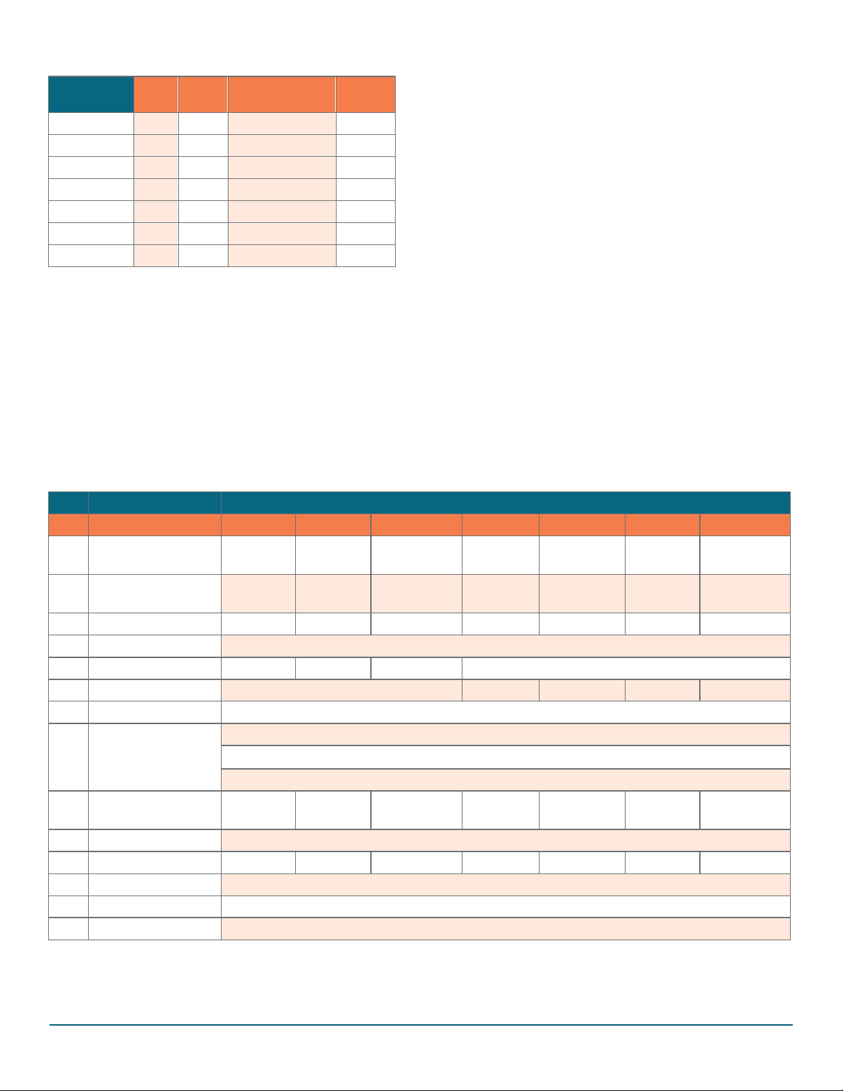
8.0 STANDARD SPECIFICATIONS
(3000 ft. elevation and below)
Model
Hp
CFM
Max Recommended
Operation Vacuum
Line Size
(OD)
VPDB-3
3
55
11” Hg
1½”
VPDB-5
5
100
11.5” Hg
2”
VPDB-7.5
7.5
155
11.5” Hg
2½”
VPDB-10
10
170
11.5” Hg
2½”
VPDB-10/3
10
235
11.5” Hg
3”
VPDB-15
15
250
11.5” Hg
3”
VPDB-20
20
470
11.5” Hg
4”
Information shown is for standard VPDB series Positive
Displacement vacuum pumps. Specifications will be
reduced for 50Hz. Specifications will change when the
pump is operated at elevations 2000 ft. or more above
sea level (see section below).
NOTE: Refer to special job drawings for custom unit
information if applicable. Verify nameplate information on
motor before installing and operating. All information is
subject to change without notice.
10.0 PARTS LIST
9.0 OPERATING AT HIGHER ELEVATIONS
(3000 ft. above sea level or more)
Atmospheric pressure is lower at higher elevations and
as a result, the compression of air by the pump requires
more work for vacuum conveying. In these higher
altitude applications, the pressure relief valve of VPDB
pumps must be adjusted to prevent the pump from damaging itself or the motor by attempting to compress air of
reduced density to an unsafe level. Failure to adjust the
pump will void the pump warranty.
When the end-use site is known, Novatec endeavors to
pre-adjust the vacuum pump’s performance at the factory
to compensate for elevations above 3000 feet. Novatec
then labels the vacuum relief valve accordingly. If your
pump-use site is 3000 feet above sea level or more, and
no indication of pre-adjustment is present on the pump
assembly, please contact Novatec Engineering or the
Novatec Service Department at the number on the front
cover of this manual to get instructions for adjusting your
VPDB pump for use at elevations at 3000 feet or more
above sea level.
QTY
DESCRIPTION
MODEL
VPDB-3
VPDB-5
VPDB-7.5
VPDB-10
VPDP-10/3
VPDB-15
VPDB-20
1
Blower,
PD-3M
HORZ
PD-3M-
HORZ
PD-4M-
HORZ
PD-4M-
HORZ
PD-4M-
HORZ
PD-5M-
HORZ
MVP-P408-
HORIZ
1
Motor
8/230/460/3/60
01913
01914
01915
01916
01916
01917
98-0868
1
Motor 575/3/60
04202
04199
04823
03596
03596
04200
14294
1
Vacuum Gauge
50011
2
V-Belt
BX55
BX57
BX57
3
V-Belt
BX57
BX55
BX57
BX59
1
Regulator Assembly
115 VAC = asVPDB-AR-07
24 VDC = asVPDB-AR-03
24 VAC = asVPDB-AR-06
1
Vacuum Breaker
Valve Assy
VBV-15-
NPT
VBV-20-
NPT
VBV-25-NPT
VBV-25-
NPT
VBV-30-
NPT
VBV-30-
NPT
VBV-40-ST
1
Motor Starter
Contact Factory – [email protected]
1
Filter Element
hf-047
hf-047
hf-047
hf-048
hf-048
hf-048
1
Regulator
50154
1
Regulator Bracket
07-1397
*
Lubrication Oil
Gardner Denver AEON PD-XD Lubricating Oil. NOVATEC P/N VPDB-QT and VPDB-CASE
*See lubrication chart on page 11 to determine stocking level for oil.
NOTE: Parts shown are for standard VPDB series vacuum pumps. Refer to special job drawings for custom unit information.
Verify information on existing part before ordering and installing replacement. All information is subject to change without notice.
Page 9
9
11.0 MAINTENANCE AND INSPECTION
SCHEDULE
It is recommended that maintenance and inspection is
done on a scheduled basis. Maintenance requirements
will naturally vary widely for each installation and specific operating conditions. It is suggested that a complete
inspection be performed with the necessary maintenance
at the end of the first day, the first week, the first month
and the first 3 months. These inspections will be indicative of how often future maintenance will be necessary.
Every Week
Inspect the Filter cartridge. Clean or replace as required.
Remove any fines collected from the catch pan. This
time interval should be shortened if experience indicates
unusual dust loading. Check the system for air leaks and
correct as required.
Every Month
Inspect the vacuum breaker valve filter/silencer. Clean or
replace as required.
If service to the vacuum breaker is required remove it
from the filter housing.
Every 6 Months
Disconnect power and check for loose electrical
connections. Tighten all bolts and nuts that may have
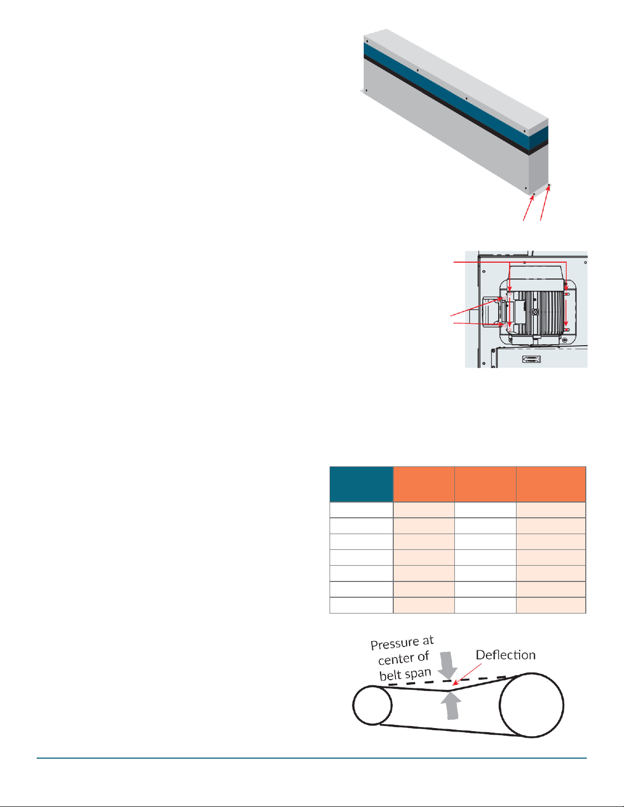
To inspect or replace belts
remove 2 bolts from each
end of belt guard and lift
belt guard vertically.
Bolt belt guard back in place
when maintenance complete.
Slightly loosen 4 each
hex nuts on the motor base
just enough to allow the
motor to slide on the base.
Use 9/16” wrench for
3 through 10 Hp units.
Use 3/4” wrench for
3 through 10 Hp units.
Adjust 1 bolt on each side
Figure 4
Typical both sides
loosened due to vibration.
11.1 Belt Adjustment and Replacement
11.1.1 Inspecting V- Belts
1. Remove the pump from service and disconnect
electrical power.
2. To inspect V-belts, remove the 2 bolts on ends of the
belt guard (see figure 4). Carefully examine each belt
for excessive stretch, looseness, frayed surfaces or
exposed cord. Replace all belts if one or more belts are
found to be excessively worn. Always replace belts as
a set; never individually.
3. Inspect the belt tension (figure 5) using the specifica-
tions in the chart, below. Once belts are found in good
condition and tensioned properly, replace the outside
panel ensuring all 4 screws are fastened properly.
Never operate the pump without the belt guard firmly
installed.
of the motor base allowing the motor to slide, loosening
or tensioning the belts.
Use 3/4” wrench for 3 through 10 Hp units.
Use 15/16” wrench for 15 and 20 Hp units.
Figure 5
Pump Model
Existing Belt
Re-tensioning
Pressure (lb.)
*New Belt
Tensioning (lb.)
Belt Deflection
at Pressure (jn.)
VPDB-3
3.4
5.1
0.31
VPDB-5
4.2
6.3
0.31
VPDB-7.5
3.6
5.4
0.31
VPDB-10
4.1
6.2
0.31
VPDB-10/3
4.1
6.2
0.31
VPDB-15
4.4
6.6
0.31
VPDB-20
4.6
6.9
0.34
Figure 6
Page 10
10
11.1.2 Replacing V Belts
If broken, stretched or excessively worn belts require
replacement:
1. Remove the entire belt guard by removing the 4 bolts
that connect the cover to the pump base (see figure 4,
page 9), and lift the cover straight up.
2. Loosen the motor’s mounting bolts and slide the motor
base towards the pump, allowing the belts to loosen.
Remove the belts (see figure 5, page 9).
3. Confirm use of the proper replacement belts (see parts
list, page 8) and install them carefully onto each sheave
pulley. All belts must be replaced as a set; never individually.
4. Re-tension the belts with the sliding motor base ac-
cording to the chart (figure 6, see page 9). Note that
new belts require greater initial tension than belts that
have been in operation. Double check the belt tension
while tightening the motor base and assure the motor
stays in alignment while re-tightening
(see figure 5, page 9).
5. Re-attach the belt guard ensuring the four mounting
bolts are tight and locking washers are in place.
Confirm that no part of the belt guard comes in contact with rotating sheaves or belts.
6. Reinstall the outside panel of the guard. All 4 bolts
must be installed for safety. Never operate the pump
without the belt guard firmly installed.
11.2 Special Note: Sheave Re-installation
In the event a new blower is fitted to your VPDB vacuum
pump assembly, it is important to assure proper place-
ment of the sheave on the pump’s drive shaft. If not,
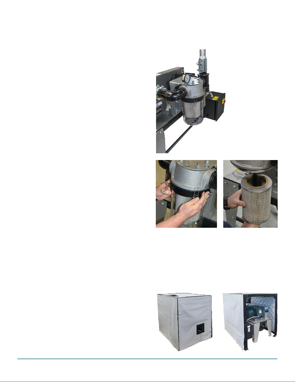
11.3 Cleaning Air-Filter
For your convenience the VPDB is equipped with a filter
cartridge enclosed in a ClearVu cannister which allows
you to know exactly when you need to clean or replace
the filter element.
Filter Element in ClearVu Canister
misalignment and unacceptable “overhang” can occur,
prematurely wearing the seals and bearings of the pump.
Position of Sheave Pulley on VPDB Pump Drive Shaft:
CRITICAL NOTE:
On 3 and 5 Hp units: the bushing must be 1/32” – 1/16”
from the blower face. This will result in a 5/16” between
the blower face and the sheave.
Release clamps to remove
ClearVu cannister.
Pull cannister straight down
and empty any dust.
11.4 Removing Sound Curtains
Pull filter straight down
to clean or replace.
On the 10 through 15 Hp units: the bushing is held with-
in the sheave. There should be ¼” between the blower
face and the sheave.
On the 20 Hp units: Position of Sheave Pulley on Pump
Drive Shaft: The distance between the blower face and
the installed pulley face must not exceed 0.38”.
If you have the optional sound curtain kit, panels can
easily be removed for access to perform maintenance.
Page 11
11
on-
-
CAUTION:
DO NOT OVERFILL the
pump with lubricant!
Severe damage can occur
and warranty will be void.
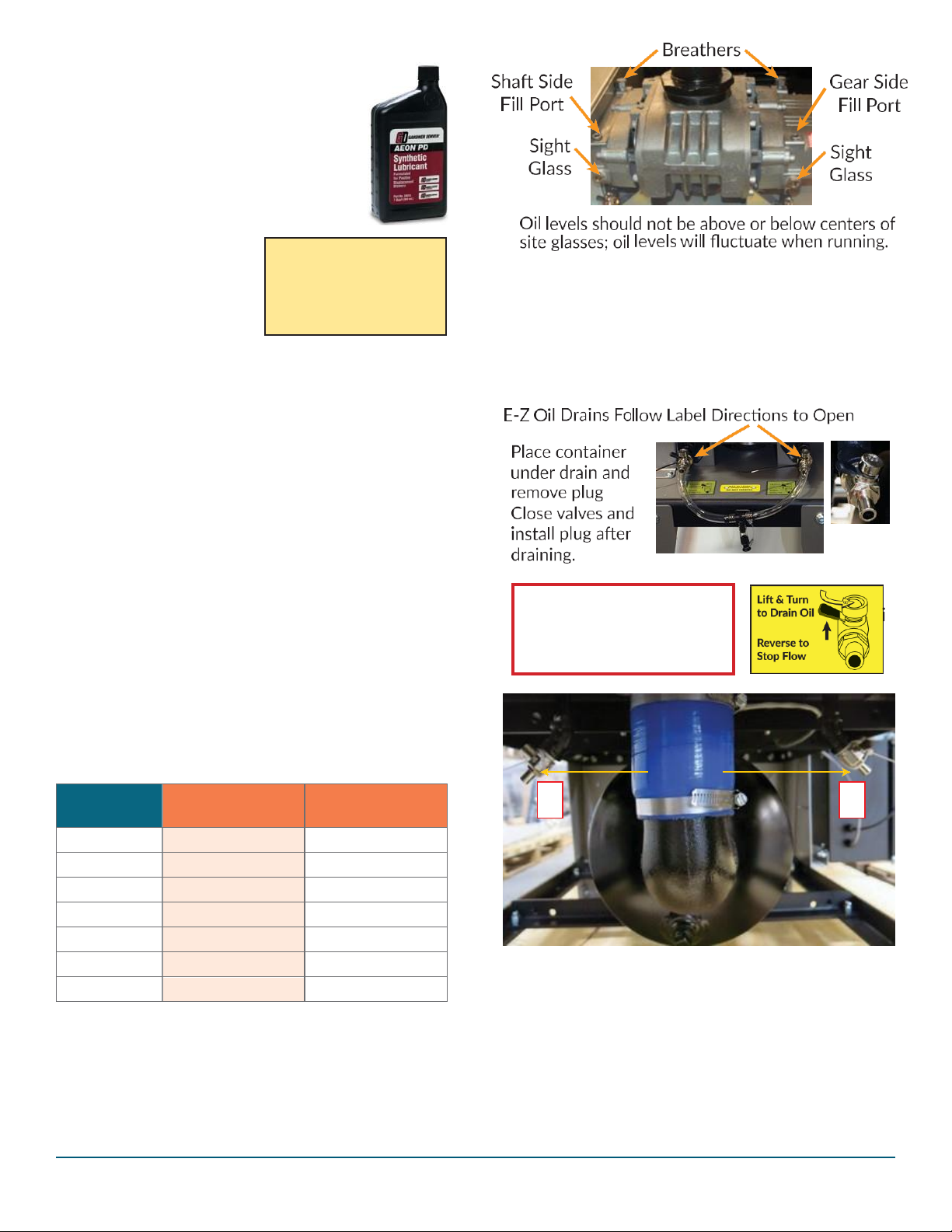
Place container under each
drain. Lift black tab to open
valves. Close valves when oil
is drained.
11.5 Blower Lubrication
Novatec VPDB Series vacuum pumps use horiz
tally installed Gardner Denver positive displace
ment blowers.
Gardner Denver recommends and
Novatec uses:
Gardner Denver AEON PD-XD Lubrication
or approved equivalent
NOVATEC P/N VPDB-QT (1qt.)
or P/N VPDB-CASE (12 qts.)
Lubrication Guidelines
1. Novatec model MVP series
vacuum pumps include
splash lubricated bearings
that require no grease, but both the gear and shaft
sides of the pump unit
contain oil sumps that must be maintained as part
of your lubrication and oil replacement procedures.
2. The lubrication should be changed after initial 500
hours of operation and then after every 1500 hours.
3. The proper level should be in the middle of the sight
gauge when the blower is not operating. DO NOT
OVERFILL OIL SUMPS or damage to the blower may
occur.
4. The oil level may naturally rise and/or fall in the gauge
during operation, but the oil level should not fall below
the middle of the site gauge when the blower is idle.
5. Routine “topping up” of oil levels is NOT advised. Each
pump examination should include stopping the pump,
allowing the oil level to stabilize and then checking the
level in the sight glass windows before adding oil to
the required level.
Novatec VPDB Vacuum Pump Lubrication Capacities:
Pump Model
Shaft Side Oil
Sump Capacity (oz,)
Gear Side Oil
Sump Capacity (oz,)
VPDB-3
9.0
18.0
VPDB-5
9.0
18.0
VPDB-7.5
11.0
24.0
VPDB-10
11.0
24.0
VPDB-10/3
11.0
24.0
VPDB-15
19.1
40.0
VPDB-20
20.0
32.0
Lubrication fill ports are located on the top of the blower.
Sight glasses are located on the side of the blower. Oil
level should be maintained up to the middle of the sight
glass when the pump is idle. Be sure to maintain oil levels
on both sides. Do not operate a pump with an insufficient
lubricant level. Do Not Overfill.
On VPDB-20, oil drains are located under the pump deck.
1. Shaft Side:
2. Gear Side
EZ Drain
2
1
Page 12

12
12.0 WARRANTY
NOVATEC, INC. - EFFECTIVE DATE 1 APRIL 2019
NOVATEC, INC. offers COMPREHENSIVE PRODUCT WARRANTIES on
all of our plastics auxiliary equipment. We warrant each NOVATEC
manufactured product to be free from defects in materials and
workman- ship, under normal use and service for the periods listed
under “Warranty Periods”. The obligation of Novatec, under this
warranty, is limited to repairing or furnishing, without charge, a similar
part to replace any part which fails under normal use due to a material
or workmanship defect, within its respective warranty period. It is the
purchaser’s responsibility to provide Novatec with immediate written
notice of any such suspect- ed defect. Warranted replacement parts are
billed and shipped freight pre-paid. The purchaser must return the
suspect defective part, freight prepaid and with identifying
documentation to receive full credit for
the part returned. Novatec shall not be held liable for damages or delay
caused by defects. No allowance will be made for repairs or alterations
without the written consent or approval of Novatec.
The provisions in equipment specifications are descriptive, unless
expressly stated as warranties. The liability of Novatec to the purchaser,
except as to title, arising out of the supplying of the said equipment, or
its use, whether based upon warranty, contract or negligence, shall not
in any case exceed the cost of correcting defects in the equipment as
herein provided. All such liability shall terminate upon the expiration
of said warranty periods. Novatec shall not in any event be held liable
for any special, indirect or consequential damages. Commodities not
manufactured by Novatec are warranted and guaranteed to Novatec
by the original manufacturer and then only to the extent that Novatec
is able to enforce such warranty or guaranty. Novatec, Inc. has not au-
thorized anyone to make any warranty or representation other than the
warranty contained here. Non-payment of invoice beyond 90 days will
invalidate the warranty. A renewed warranty can be purchased directly
from Novatec.
Please note that we always strive to satisfy our customers in whatever
manner is deemed most expedient to overcome any issues in connection with our equipment.
Warranty Periods:
Note: All warranty periods commence with the shipment of the equipment to the customer.
Resin Drying to Include:
NovaWheel™ Dryers *
Dual Bed Dryers
NovaDrier *
NDM-5 Membrane Dryer
Gas-Fired Process Heaters
Gas-Fired Regeneration Heaters
Drying Hoppers
Central Drying Hopper Assemblies
Heater/Blower Units and Hot-Air Dryer
Silo Dehumidifiers
NovaVac Dryers *
Nitrodry Nitrogen Dryers
DryTemp Plus
Central System Controls to Include:
FlexTouch™ Series Controls
FlexXpand™ Series Controls
OptiFlex™ Series Controls
PLC Communications Modules
Greenboard Communications Modules
LOGO! Mini PLC
MCS-600 Series Controls – (Distributed I/O)
MCS-400 Series Controls
CL Silo Manager
5-YEAR (Except 1-Year on Non-Novatec Buy-Out Items)
Resin Blending and Feeding to Include:
WSB Blenders, MaxiBatch & Feeders *
Gaylord Sweeper Systems
Downstream Extrusion Equipment to Include:
C and NC Bessemer Series Cutters
NPS Bessemer Series Pullers
NPC Mini Puller/Cutter
All NS Series Servo Saws
Rx SmartMed Extrusion Products
All Cooling and Vacuum Tanks Manufactured by Novatec
Resin Conveying and Systems Components to Include:
GSL Series Vacuum Loaders
GlassVu Loaders, Receivers and Hoppers
VL/VLP Series Loaders
VRH, VR, VR-FL, VRP & VRM Series Receivers
Compressed Air Loaders
AL-B Barrel Loader
Cyclone Dust Collectors
Conveying System Accessories
Surge Bins
Valves and Accessories
Electronic Metal Separators
Quick Select Manifolds
Tilt Tables
Moisture Measurement Equipment to Include:
MoistureMaster
®
PET Resin Crystallizers
Filter Dust Collectors
Drawer Magnets
Velocity Control Valves
Resin Conveying System Components to Include:
** VPDB Vacuum Positive Displacement Pumps
** SVP Vacuum Pumps
** MVP Vacuum Pumps
** Railcar Unloading Systems
3-YEAR
**5-Year Extended Warranty - When a MachineSense® data plan is activated for products with **, Novatec automatically extends the warranty to 5 years.
The data plan must be activated within 60 days after product shipment, and remain active through the warranty period to maintain extended warranty
eligibility. The first 6-months of data plan usage is free from Novatec.
1-YEAR
Infrared Dryers
UltraVac Vacuum Pumps
Vacuum Regenerative Blower Pumps
Custom Equipment of any kind unless otherwise specified
Page 13

13
Exclusions:
Routine maintenance/replacement parts are excluded from the warranty. These include, but are not limited to: hoses, desiccant, filters,
filter elements, wiper seals, gaskets, dew point sensors, infrared lamps,
motors, internal solenoids, fuses and motor brushes. Use with abrasive
materials will void the warranty of any standard product. Wear resistant
options may be available to extend usable service life with abrasive materials. Novatec reserves the right to limit the warranty if the customer
installs replacement parts that do not meet the specifications of the
original parts supplied by Novatec.
*Specific Exclusions:
1. NovaDrier™ and NITROdry™ warranty is void if coalescing filters are
not replaced on a 6-month or yearly basis (per instruction manual)
and/or membrane has been exposed to ozone.
2. NovaVac Dryer -The ability of the canisters to hold vacuum will be
compromised if the vacuum seal edge is damaged from mishandling.
We do not warranty canisters damaged from improper handling. We
do, however, warranty the seals.
3. LOAD CELLS on our WSB’s are covered by Novatec standard warran-
ty as long as they have not been damaged from improper handling.
4. Desiccant Wheel Warranty will be void if the wheel has been exposed
to plasticizer, dust or other contaminants as a result of negligence on
the part of the processor.
5. DryTemp+ - We assume no responsibility from equipment failures
resulting from untreated or improperly treated water.
This warranty shall not apply to equipment:
1. Repaired or altered without written approval of NOVATEC unless
such repair or alteration was, in our judgment, not responsible for the
failure
2. Which has been subject to misuse, negligence, accident or incorrect
wiring by others
3. Warranty is void if processing rates exceed manufacturer-recommended levels or if damage is caused by ineffective power isolation
and/or power spikes/sags or incorrect installation.
NOTE: All conditions and content of this warranty are subject to changes without notice.
Page 14

14
Page 15

15
Page 16

Drying > Conveying > Blending > Downstream
222 East Thomas Avenue
Baltimore, Maryland 21225
www.novatec.com
Phone
410-789-4811 or 800-938-6682
24 Hour service: 800-938-6682
Fax: 410-789-4638
Email
Parts: [email protected]
Service: [email protected]
Sales: [email protected]
 Loading...