

Page 1

NovaScale
T810 E1, T830 E1,
R410 E1
User's Guide
NOVASCALE
REFERENCE
86 A1 15FA 01
Page 2

Page 3

NOVASCALE
NovaScale T810 E1,
T830 E1, R410 E1
User's Guide
Hardware
June 2008
BULL CEDOC
357 AVENUE PATTON
B.P.20845
49008 ANGERS CEDEX 01
FRANCE
REFERENCE
86 A1 15FA 01
Page 4
Proprietary Notice and Liability Disclaimer
The information disclosed in this document, including all designs and related materials, is the valuable property of
NEC Computers and/or its licensors. NEC Computers and/or its licensors, as appropriate, reserve all patent,
copyright and other proprietary rights to this document, including all design, manufacturing, reproduction, use, and
sales rights thereto, except to the extent said rights are expressly granted to others.
To allow for design and specification improvements, the information in this document is subject to change at any
time, without notice. Reproduction of this document or portions thereof without prior written approval of NEC
Computers is prohibited.
The Bull product(s) discussed in this document are warranted in accordance with the terms of the Warranty Statement
accompanying each product. However, actual performance of each product is dependent upon factors such as
system configuration, customer data, and operator control. Since implementation by customers of each product may
vary, the suitability of specific product configurations and applications must be determined by the customer and is
not warranted by Bull.
Trademarks
NEC ESMPRO, NEC DianaScope, NEC MWA, and ExpressBuilder are trademarks or registered trademarks of NEC
Corporation.
NovaScale is a registered trademark of Bull SAS.
Adobe, and Adobe Acrobat are registered trademarks of Adobe Systems, Incorporated.
Microsoft, Microsoft Windows, Windows NT, Windows 95, Windows 98, Windows2000 and Windows Server
2003 are all registered trademarks of Microsoft Corporation.
MS-DOS is a registered trademark of Microsoft Corporation.
Intel and Xeon are registered trademarks of Intel Corporation.
All other product, brand, or trade names used in this publication are the trademarks or registered trademarks of their
respective trademark owners.
Copyright © NEC Computers SAS 2006
Suggestions and criticisms concerning the form, content, and presentation of this manual
are invited. A form is provided at the end of this manual for this purpose.
The information in this document is subject to change without notice. Bull will not be liable for errors contained herein, or for
incidental or consequential damages in connection with the use of this material.
Page 5

User Guide
5
www.bull.com
Table of Contents
Table of Contents . . . . . . . . . . . . . . . . . . . . . . . . . . . . . . . . . . . . . . . . . . . . . 5
Text Conventions . . . . . . . . . . . . . . . . . . . . . . . . . . . . . . . . . . . . . . . . . . . . . . . . . . . . . . . . . . . . . 13
Safety Notices . . . . . . . . . . . . . . . . . . . . . . . . . . . . . . . . . . . . . . . . . . . . . . . 14
Regulatory Information . . . . . . . . . . . . . . . . . . . . . . . . . . . . . . . . . . . . . . . . . . . . . . . . . . . . . . . . 14
European Notice ............................................................................................................ 14
USA and Canada Notice................................................................................................ 15
Modifications to the Product.......................................................................................... 15
Connections and Remote Earths.................................................................................... 15
Power Supply and Cables.............................................................................................. 16
Batteries......................................................................................................................... 16
Chassis Cover Removal and Replacement .................................................................... 16
Laser Compliance Statement......................................................................................... 17
Warning - Hazardous Voltage!...................................................................................... 17
Warning -Avoid Electrostatic Discharge!...................................................................... 17
Product Disposal............................................................................................................ 17
System Features . . . . . . . . . . . . . . . . . . . . . . . . . . . . . . . . . . . . . . . . . . . . . 18
Related Documents . . . . . . . . . . . . . . . . . . . . . . . . . . . . . . . . . . . . . . . . . . . . . . . . . . . . . . . . . . . 19
NovaScale T810 E1 System Chassis Features. . . . . . . . . . . . . . . . . . . . . . . . . . . . . . . . . . . . . . 20
Front View..................................................................................................................... 20
NovaScale T810 E1 Rear View..................................................................................... 21
NovaScale T810 E1 Status Indicators ........................................................................... 22
NovaScale T810 E1 Internal View................................................................................ 23
NovaScale R410 E1 System Chassis Features. . . . . . . . . . . . . . . . . . . . . . . . . . . . . . . . . . . . . 24
Front View..................................................................................................................... 24
NovaScale R410 E1 Rear View.................................................................................... 26
NovaScale R410 E1 Internal View............................................................................... 27
NovaScale T830 E1 System Chassis Features. . . . . . . . . . . . . . . . . . . . . . . . . . . . . . . . . . . . . . 28
Front View with Front Bezel......................................................................................... 28
Front View without Front Bezel.................................................................................... 29
NovaScale T830 E1 Rear View..................................................................................... 30
NovaScale T830 E1 Status Indicators ........................................................................... 31
NovaScale T830 E1 Internal View................................................................................ 33
Motherboard . . . . . . . . . . . . . . . . . . . . . . . . . . . . . . . . . . . . . . . . . . . . . . . . . . . . . . . . . . . . . . . . . 34
Motherboard Layout...................................................................................................... 34
Motherboard Jumpers.................................................................................................... 36
Back Panel Connectors.................................................................................................. 39
Memory Configuration.................................................................................................. 40
BMC Controller............................................................................................................. 41
Standard Features . . . . . . . . . . . . . . . . . . . . . . . . . . . . . . . . . . . . . . . . . . . . . . . . . . . . . . . . . . . . 43
Processor........................................................................................................................ 43
Memory.......................................................................................................................... 43
Page 6

User Guide
6
www.bull.com
Video.............................................................................................................................. 43
Network Controller........................................................................................................ 43
RAID Support................................................................................................................ 43
ACPI .............................................................................................................................. 44
Keyboard and Mouse..................................................................................................... 44
NovaScale T810 E1 Specific Features........................................................................... 45
NovaScale R410 E1 Specific Features ......................................................................... 46
NovaScale T830 E1 Specific Features........................................................................... 47
Optional Features . . . . . . . . . . . . . . . . . . . . . . . . . . . . . . . . . . . . . . . . . . . . . . . . . . . . . . . . . . . . . 48
DVD-ROM Drive.......................................................................................................... 49
DVD Writer Combination Drive ................................................................................... 50
DAT72 Tape Backup Unit (USB) ................................................................................. 51
DLT-V4 Tape Backup Unit (SATA)............................................................................. 52
DAT160 Tape Backup Unit (USB) ............................................................................... 53
GoVault Backup Unit (SATA)...................................................................................... 54
SAS Hard Disk Drive .................................................................................................... 55
S-ATA Hard Disk Drive................................................................................................ 56
Adaptec SCSI Card 29320LPE...................................................................................... 57
LSI 8708EM2 SAS/SATA RAID Controller ................................................................ 58
Setting Up Your System . . . . . . . . . . . . . . . . . . . . . . . . . . . . . . . . . . . . . . . 59
Unpacking the System . . . . . . . . . . . . . . . . . . . . . . . . . . . . . . . . . . . . . . . . . . . . . . . . . . . . . . . . . 60
Setting Up Your Server (Rack). . . . . . . . . . . . . . . . . . . . . . . . . . . . . . . . . . . . . . . . . . . . . . . . . . . 61
Setup Flow..................................................................................................................... 61
Selecting Server Site...................................................................................................... 62
NovaScale T810 E1 Rack Installation Kit Assembly . . . . . . . . . . . . . . . . . . . . . . . . . . . . . . . . . 64
Unpacking the Rack Installation Kit.............................................................................. 64
Before You Begin.......................................................................................................... 66
Static Precautions........................................................................................................... 67
Assembly ....................................................................................................................... 67
Assembling the Front and Rear Parts of Support Rails................................................. 68
Installing the Support Rails............................................................................................ 69
Attaching the Handles to the Rack Mounting Frame .................................................... 70
Installing the Rack Mounting Frame on the Server....................................................... 70
Installing the Server in the Rack Cabinet ...................................................................... 72
NovaScale R410 E1 Rack Installation Kit Assembly . . . . . . . . . . . . . . . . . . . . . . . . . . . . . . . . 73
Before You Begin.......................................................................................................... 73
Static Precautions........................................................................................................... 73
Inserting a System into a Rack ...................................................................................... 74
Installing and Removing the Rack Handles................................................................... 76
Installing a Rack Mount Kit with the Basic Rails ......................................................... 77
Installing a Rack Mount Kit with Sliding Rails (option)............................................... 83
Installing a Cable Arm (with Sliding Rails Only) ......................................................... 89
NovaScale T830 E1 Rack Installation Kit Assembly . . . . . . . . . . . . . . . . . . . . . . . . . . . . . . . . . 94
Unpacking the Rack Installation Kit.............................................................................. 94
Before You Begin.......................................................................................................... 97
Static Precautions........................................................................................................... 97
Assembly ....................................................................................................................... 98
Assembling the Front and Rear Parts of Support Rails................................................. 99
Installing the Support Rails.......................................................................................... 100
Page 7

User Guide
7
www.bull.com
Installing the Filler on the Server ................................................................................ 101
Installing the Server in the Rack Cabinet .................................................................... 102
Setting Up Your System (Tower). . . . . . . . . . . . . . . . . . . . . . . . . . . . . . . . . . . . . . . . . . . . . . . . 103
Setup Flow................................................................................................................... 103
Selecting System Site................................................................................................... 104
Making Connections. . . . . . . . . . . . . . . . . . . . . . . . . . . . . . . . . . . . . . . . . . . . . . . . . . . . . . . . . . 105
NovaScale T810 E1 Power Supply . . . . . . . . . . . . . . . . . . . . . . . . . . . . . . . . . . . . . . . . . . . . . . 106
Connecting the Power Cord......................................................................................... 106
NovaScale R410 E1 Power Supply. . . . . . . . . . . . . . . . . . . . . . . . . . . . . . . . . . . . . . . . . . . . . . 107
Connecting the Power Cord......................................................................................... 107
NovaScale T830 E1 Power Supply . . . . . . . . . . . . . . . . . . . . . . . . . . . . . . . . . . . . . . . . . . . . . . 108
Connecting the Power Cord(s)..................................................................................... 108
Hot-Swappable Power Supply Features ...................................................................... 109
Using the System. . . . . . . . . . . . . . . . . . . . . . . . . . . . . . . . . . . . . . . . . . . . 111
Powering On your System. . . . . . . . . . . . . . . . . . . . . . . . . . . . . . . . . . . . . . . . . . . . . . . . . . . . . 112
Powering Off your System. . . . . . . . . . . . . . . . . . . . . . . . . . . . . . . . . . . . . . . . . . . . . . . . . . . . . 114
Forcing a Power Shutdown . . . . . . . . . . . . . . . . . . . . . . . . . . . . . . . . . . . . . . . . . . . . . . . . . . . . 115
Resetting the System . . . . . . . . . . . . . . . . . . . . . . . . . . . . . . . . . . . . . . . . . . . . . . . . . . . . . . . . . 116
Configuring Your System . . . . . . . . . . . . . . . . . . . . . . . . . . . . . . . . . . . . . 117
Configuring RAID . . . . . . . . . . . . . . . . . . . . . . . . . . . . . . . . . . . . . . . . . . . . . . . . . . . . . . . . . . . . 118
RAID Configuration Utility......................................................................................... 118
RAID Levels................................................................................................................ 119
RAID Configuration using Intel Matrix Storage Manager . . . . . . . . . . . . . . . . . . . . . . . . . . . . 122
Description................................................................................................................... 122
Enabling RAID in the BIOS........................................................................................ 122
Entering the Intel Matrix Storage Manager................................................................. 122
Creating a RAID Volume............................................................................................ 122
Deleting a RAID Volume............................................................................................ 123
Resetting Disks to Non-RAID..................................................................................... 124
RAID Configuration using the Intel® Embedded Server RAID BIOS Configuration Utility . 125
Description................................................................................................................... 125
Enabling RAID in the BIOS........................................................................................ 125
Entering the Intel Embedded Server RAID BIOS Configuration Utility.................... 125
Setting Up the RAID Feature....................................................................................... 125
RAID Configuration using the MegaRAID Configuration Utility. . . . . . . . . . . . . . . . . . . . . . . 126
RAID Configuration using the Universal RAID Utility . . . . . . . . . . . . . . . . . . . . . . . . . . . . . . . 127
Configuring the BMC . . . . . . . . . . . . . . . . . . . . . . . . . . . . . . . . . . . . . . . . . . . . . . . . . . . . . . . . . 128
Overview...................................................................................................................... 128
Installation ................................................................................................................... 128
SYSCFG ...................................................................................................................... 128
SELVIEW.................................................................................................................... 131
Upgrading Your System . . . . . . . . . . . . . . . . . . . . . . . . . . . . . . . . . . . . . . 132
General Safety Information . . . . . . . . . . . . . . . . . . . . . . . . . . . . . . . . . . . . . . . . . . . . . . . . . . . . 132
Static Precautions. . . . . . . . . . . . . . . . . . . . . . . . . . . . . . . . . . . . . . . . . . . . . . . . . . . . . . . . . . . . 133
Equipment Log . . . . . . . . . . . . . . . . . . . . . . . . . . . . . . . . . . . . . . . . . . . . . . . . . . . . . . . . . . . . . . 133
Tools Recommended for Upgrading Your System . . . . . . . . . . . . . . . . . . . . . . . . . . . . . . . . . 133
Preparing Your System for Upgrade. . . . . . . . . . . . . . . . . . . . . . . . . . . . . . . . . . . . . . . . . . . . . 133
Cabling SATA Devices . . . . . . . . . . . . . . . . . . . . . . . . . . . . . . . . . . . . . . . . . . . . . . . . . . . . . . . . 134
Page 8

User Guide
8
www.bull.com
The S-ATA Cable........................................................................................................ 134
System Power Cables................................................................................................... 134
Cabling a S-ATA Drive............................................................................................... 135
Cabling SAS Devices . . . . . . . . . . . . . . . . . . . . . . . . . . . . . . . . . . . . . . . . . . . . . . . . . . . . . . . . . 136
The SAS Cable............................................................................................................. 136
Interrupt Requests . . . . . . . . . . . . . . . . . . . . . . . . . . . . . . . . . . . . . . . . . . . . . . . . . . . . . . . . . . . 138
NovaScale T810 E1 Upgrade . . . . . . . . . . . . . . . . . . . . . . . . . . . . . . . . . . 139
Removing or Installing the Right Side Door. . . . . . . . . . . . . . . . . . . . . . . . . . . . . . . . . . . . . . . 139
Removing the Right Side Door.................................................................................... 139
Replacing the Right Side Door.................................................................................... 140
Removing and Replacing the Front Panel . . . . . . . . . . . . . . . . . . . . . . . . . . . . . . . . . . . . . . . . 141
Removing the Front Panel ........................................................................................... 141
Replacing the Front Panel............................................................................................ 141
Installing or Removing a 5.25-inch Device. . . . . . . . . . . . . . . . . . . . . . . . . . . . . . . . . . . . . . . . 142
Adding a 5.25-inch Device.......................................................................................... 142
Removing a 5.25-inch device ...................................................................................... 143
Installing or Removing a 3.5-inch Floppy Disk Drive . . . . . . . . . . . . . . . . . . . . . . . . . . . . . . . 144
Removing a 3.5-inch Floppy Disk Drive..................................................................... 144
Installing a 3.5-inch Floppy Disk Drive ...................................................................... 144
Installing or Removing Hard Disk Drives . . . . . . . . . . . . . . . . . . . . . . . . . . . . . . . . . . . . . . . . . 145
Removing a Hard Disk Drive ...................................................................................... 145
Installing a Hard Disk Drive........................................................................................ 146
Installing and Removing an Expansion Card. . . . . . . . . . . . . . . . . . . . . . . . . . . . . . . . . . . . . . 148
Specific Recommendations.......................................................................................... 148
Installing an Expansion Card....................................................................................... 150
Removing an Expansion Card from Your System....................................................... 151
Upgrading Microprocessor . . . . . . . . . . . . . . . . . . . . . . . . . . . . . . . . . . . . . . . . . . . . . . . . . . . . 152
Removing a Processor ................................................................................................. 152
Installing a CPU........................................................................................................... 153
Upgrading Random Access Memory (RAM). . . . . . . . . . . . . . . . . . . . . . . . . . . . . . . . . . . . . . . 155
Recommended Memory Configuration....................................................................... 155
Checking System Memory........................................................................................... 155
Removing and Replacing a DDR2 module.................................................................. 155
Replacing the Battery. . . . . . . . . . . . . . . . . . . . . . . . . . . . . . . . . . . . . . . . . . . . . . . . . . . . . . . . . 157
NovaScale R410 E1 Upgrade. . . . . . . . . . . . . . . . . . . . . . . . . . . . . . . . . . 158
Removing and Replacing the Front Bezel . . . . . . . . . . . . . . . . . . . . . . . . . . . . . . . . . . . . . . . . 158
Removing the Front Bezel........................................................................................... 158
Installing the Front Bezel............................................................................................. 159
Removing or Installing the Server Cover . . . . . . . . . . . . . . . . . . . . . . . . . . . . . . . . . . . . . . . . . 160
Removing the Server Cover......................................................................................... 160
Installing the Server Cover.......................................................................................... 161
Removing or Installing the Processor Duct. . . . . . . . . . . . . . . . . . . . . . . . . . . . . . . . . . . . . . . 162
Removing the Processor Air Duct............................................................................... 162
Installing the Processor Air Duct................................................................................. 163
Installing or Removing a 5.25-inch Device. . . . . . . . . . . . . . . . . . . . . . . . . . . . . . . . . . . . . . . . 164
Installing a Slimline Optical Device............................................................................ 164
Removing a Slimline Optical Drive............................................................................. 167
Installing or Removing Hard Disk Drives . . . . . . . . . . . . . . . . . . . . . . . . . . . . . . . . . . . . . . . . . 170
Installing a Hard Disk Drive........................................................................................ 171
Page 9

User Guide
9
www.bull.com
Removing a Hard Disk Drive ...................................................................................... 175
Installing or Removing the Motherboard . . . . . . . . . . . . . . . . . . . . . . . . . . . . . . . . . . . . . . . . . 177
Removing the Motherboard......................................................................................... 177
Replacing the Power Supply . . . . . . . . . . . . . . . . . . . . . . . . . . . . . . . . . . . . . . . . . . . . . . . . . . . 180
Replacing the Front Panel Board . . . . . . . . . . . . . . . . . . . . . . . . . . . . . . . . . . . . . . . . . . . . . . . 185
Replacing a Cooling Fan . . . . . . . . . . . . . . . . . . . . . . . . . . . . . . . . . . . . . . . . . . . . . . . . . . . . . . 187
Replacing the System Blower Fans............................................................................. 187
Replacing the PCI Cooling Fan................................................................................... 191
Cable Routing . . . . . . . . . . . . . . . . . . . . . . . . . . . . . . . . . . . . . . . . . . . . . . . . . . . . . . . . . . . . . . . 192
Power Cable Routing................................................................................................... 192
Data Cable Routing...................................................................................................... 193
Upgrading Microprocessor . . . . . . . . . . . . . . . . . . . . . . . . . . . . . . . . . . . . . . . . . . . . . . . . . . . . 194
Removing a Processor ................................................................................................. 194
Installing a Processor................................................................................................... 195
Upgrading Random Access Memory (RAM). . . . . . . . . . . . . . . . . . . . . . . . . . . . . . . . . . . . . . . 198
Recommended Memory Configuration....................................................................... 198
Removing and Replacing a DDR2 module.................................................................. 198
Installing and Removing the PCI Riser Assembly. . . . . . . . . . . . . . . . . . . . . . . . . . . . . . . . . . 200
Removing the PCI Riser Assembly............................................................................. 200
Installing the PCI Riser Assembly............................................................................... 201
Installing and Removing a PCI Riser Card . . . . . . . . . . . . . . . . . . . . . . . . . . . . . . . . . . . . . . . . 202
Removing a PCI Riser Card......................................................................................... 202
Installing a PCI Riser Card.......................................................................................... 203
Installing and Removing a PCI Add-in Card. . . . . . . . . . . . . . . . . . . . . . . . . . . . . . . . . . . . . . . 204
Installing a PCI Add-in Card....................................................................................... 204
Removing a PCI Add-in Card...................................................................................... 205
NovaScale T830 E1 Chassis Upgrade . . . . . . . . . . . . . . . . . . . . . . . . . . . 207
Removing or Installing the Left side cover . . . . . . . . . . . . . . . . . . . . . . . . . . . . . . . . . . . . . . . 207
Removing the Left Side Cover .................................................................................... 207
Replacing the Left Side Cover..................................................................................... 208
Removing and Replacing the Front Panel . . . . . . . . . . . . . . . . . . . . . . . . . . . . . . . . . . . . . . . . 209
Removing the Front Panel ........................................................................................... 209
Replacing the Front Panel............................................................................................ 210
Installing or Removing a 5.25-inch Device. . . . . . . . . . . . . . . . . . . . . . . . . . . . . . . . . . . . . . . . 211
Adding a 5.25-inch Device.......................................................................................... 211
Removing a 5.25-inch Drive........................................................................................ 213
Hot-Swap Hard Disk Drives . . . . . . . . . . . . . . . . . . . . . . . . . . . . . . . . . . . . . . . . . . . . . . . . . . . . 214
Removing and Replacing a Hot-Swap Hard Disk Drive............................................. 214
Cabling the Hot-Swap Hard Disk Drive Cages........................................................... 217
Upgrading Microprocessor . . . . . . . . . . . . . . . . . . . . . . . . . . . . . . . . . . . . . . . . . . . . . . . . . . . . 220
Removing a Processor ................................................................................................. 220
Installing a CPU........................................................................................................... 221
Upgrading Random Access Memory (RAM). . . . . . . . . . . . . . . . . . . . . . . . . . . . . . . . . . . . . . . 223
Recommended Memory Configuration....................................................................... 223
Checking System Memory........................................................................................... 223
Removing and Replacing a DDR2 module.................................................................. 223
Replacing the Battery. . . . . . . . . . . . . . . . . . . . . . . . . . . . . . . . . . . . . . . . . . . . . . . . . . . . . . . . . 225
Installing and Removing an Expansion Card. . . . . . . . . . . . . . . . . . . . . . . . . . . . . . . . . . . . . . 226
Specific Recommendations.......................................................................................... 226
Installing an Expansion Card....................................................................................... 227
Removing an Expansion Card ..................................................................................... 229
Page 10

User Guide
10
www.bull.com
Installing and Using Utilities. . . . . . . . . . . . . . . . . . . . . . . . . . . . . . . . . . . 231
With the ExpressBuilder DVD you can:...................................................................... 231
Software End-User License Agreement ...................................................................... 231
Utilities......................................................................................................................... 231
ExpressBuilder . . . . . . . . . . . . . . . . . . . . . . . . . . . . . . . . . . . . . . . . . . . . . . . . . . . . . . . . . . . . . . 232
ExpressBuilder for Windows-Based (Master Control Menu) ..................................... 233
Intel Matrix Storage Manager (Windows Interface) . . . . . . . . . . . . . . . . . . . . . . . . . . . . . . . . . 235
Installing the Operating System with Express Setup. . . . . . . . . . . . . . . 236
About Express Setup.................................................................................................... 236
Installing Microsoft Windows Server 2003 . . . . . . . . . . . . . . . . . . . . . . . . . . . . . . . . . . . . . . . 237
Installation Notice........................................................................................................ 237
Installing Windows Server 2003.................................................................................. 238
Installing Drivers or Software . . . . . . . . . . . . . . . . . . . . . . . . . . . . . . . . . . . . . . . . . . . . . . . . . . 240
Installing Microsoft Windows Server 2003 . . . . . . . . . . . . . . . . . . . . . . . 241
Before Installing Windows Server 2003 . . . . . . . . . . . . . . . . . . . . . . . . . . . . . . . . . . . . . . . . . . 241
Installing Service Pack................................................................................................. 241
Updating System.......................................................................................................... 241
Re-installing to the Hard Disk which has been upgraded to Dynamic Disk ............... 241
Manual Installation when the Disk Array Controllers are Connected......................... 241
Magneto-Optical device............................................................................................... 241
Partition Size................................................................................................................ 242
Installing Microsoft Windows Server 2003. . . . . . . . . . . . . . . . . . . . . . . . . . . . . . . . . . . . . . . . 243
Creating "Windows 2003 OEM-DISK for ExpressBuilder" ...................................... 243
Windows Server 2003 Clean Installation .................................................................... 245
Upgrade installation..................................................................................................... 246
Reinstallation to Multiple Logical drives .................................................................... 248
Updating the System.................................................................................................... 249
Driver Installation and Device Settings . . . . . . . . . . . . . . . . . . . . . . . . . . . . . . . . . . . . . . . . . . 250
PROSet......................................................................................................................... 250
Network Driver............................................................................................................ 250
Re-install the Network Driver...................................................................................... 251
Graphics Accelerator Driver........................................................................................ 251
Installing SCSI Controller Driver................................................................................ 252
Installing RAID Controller Driver............................................................................... 252
Available Switch Options for Windows Server 2003 Boot.ini File ............................ 253
Setting for Collecting Memory Dump (Debug Information) . . . . . . . . . . . . . . . . . . . . . . . . . . 254
NovaScale R410 E1 Security with Mechanical Locks and Monitoring . . . . . . . . . . . . . . . . . 255
Front Bezel Lock ......................................................................................................... 255
NovaScale T830 E1 Security with Mechanical Locks and Monitoring. . . . . . . . . . . . . . . . . . 256
Front Door Lock .......................................................................................................... 256
Rear Door Padlock Loop ............................................................................................. 256
Maintenance. . . . . . . . . . . . . . . . . . . . . . . . . . . . . . . . . . . . . . . . . . . . . . . . 257
Making Backup Copies. . . . . . . . . . . . . . . . . . . . . . . . . . . . . . . . . . . . . . . . . . . . . . . . . . . . . . . . 257
Cleaning. . . . . . . . . . . . . . . . . . . . . . . . . . . . . . . . . . . . . . . . . . . . . . . . . . . . . . . . . . . . . . . . . . . . 258
Cleaning the External Surfaces of the system ............................................................ 258
Cleaning the Interior of the system.............................................................................. 258
Page 11

User Guide
11
www.bull.com
Cleaning the Keyboard ................................................................................................ 259
Cleaning the Mouse..................................................................................................... 260
Cleaning an Optical Disc Drive................................................................................... 261
Care and Handling . . . . . . . . . . . . . . . . . . . . . . . . . . . . . . . . . . . . . . . . . . . . . . . . . . . . . . . . . . . 263
Solving Problems . . . . . . . . . . . . . . . . . . . . . . . . . . . . . . . . . . . . . . . . . . . 264
Static Precautions. . . . . . . . . . . . . . . . . . . . . . . . . . . . . . . . . . . . . . . . . . . . . . . . . . . . . . . . . . . . 264
Troubleshooting Guide . . . . . . . . . . . . . . . . . . . . . . . . . . . . . . . . . . . . . . . . . . . . . . . . . . . . . . . 265
System Viewers ........................................................................................................... 265
Problems at initial System Start-up . . . . . . . . . . . . . . . . . . . . . . . . . . . . . . . . . . . . . . . . . . . . . 266
Problems After the System Has Been Running Correctly . . . . . . . . . . . . . . . . . . . . . . . . . . . 267
Problems Running New Application Software. . . . . . . . . . . . . . . . . . . . . . . . . . . . . . . . . . . . . 268
Problems and Suggestions . . . . . . . . . . . . . . . . . . . . . . . . . . . . . . . . . . . . . . . . . . . . . . . . . . . . 269
Problems with the System............................................................................................ 270
Problems with Windows Server 2003 ......................................................................... 273
Problems with ExpressBuilder..................................................................................... 275
Problems with Express Setup ...................................................................................... 276
Problems with Disk Array Configuration ................................................................... 277
Problems with Master Control Menu .......................................................................... 277
Problems with Disk Array Configuration.................................................................... 277
Collecting Event Log . . . . . . . . . . . . . . . . . . . . . . . . . . . . . . . . . . . . . . . . . . . . . . . . . . . . . . . . . 278
Collecting Configuration Information . . . . . . . . . . . . . . . . . . . . . . . . . . . . . . . . . . . . . . . . . . . 279
Collecting Dr. Watson Diagnostic Information . . . . . . . . . . . . . . . . . . . . . . . . . . . . . . . . . . . . 280
Memory Dump (depending on your configuration). . . . . . . . . . . . . . . . . . . . . . . . . . . . . . . . . 281
If You Need Assistance . . . . . . . . . . . . . . . . . . . . . . . . . . . . . . . . . . . . . . . . . . . . . . . . . . . . . . . 282
Error Messages. . . . . . . . . . . . . . . . . . . . . . . . . . . . . . . . . . . . . . . . . . . . . . . . . . . . . . . . . . . . . . 283
POST Error Messages.................................................................................................. 283
POST Error Beep Codes.............................................................................................. 283
POST Error Pause Option............................................................................................ 284
Diagnostic LEDs.......................................................................................................... 284
BIOS Setup Utility . . . . . . . . . . . . . . . . . . . . . . . . . . . . . . . . . . . . . . . . . . . 288
Using the BIOS Setup Utility . . . . . . . . . . . . . . . . . . . . . . . . . . . . . . . . . . . . . . . . . . . . . . . . . . . 288
BIOS Setup Configuration Settings . . . . . . . . . . . . . . . . . . . . . . . . . . . . . . . . . . . . . . . . . . . . . 289
Main Menu................................................................................................................... 290
Advanced Menu........................................................................................................... 291
Security Menu.............................................................................................................. 296
Server Management Menu........................................................................................... 297
Boot Options Menu...................................................................................................... 299
Boot Manager Menu.................................................................................................... 300
Error Manager Menu ................................................................................................... 301
Exit Menu .................................................................................................................... 302
Updating the BIOS . . . . . . . . . . . . . . . . . . . . . . . . . . . . . . . . . . . . . . . . . . . . . . . . . . . . . . . . . . . 303
Recording the Current BIOS Settings.......................................................................... 303
Performing the BIOS Update....................................................................................... 303
How to Identify BIOS Revision Level . . . . . . . . . . . . . . . . . . . . . . . . . . . . . . . . . . . . . . . . . . . . 304
Recovering BIOS. . . . . . . . . . . . . . . . . . . . . . . . . . . . . . . . . . . . . . . . . . . . . . . . . . . . . . . . . . . . . 305
Page 12

User Guide
12
www.bull.com
NovaScale T810 E1 Specifications. . . . . . . . . . . . . . . . . . . . . . . . . . . . . . 306
NovaScale R410 E1 Specifications . . . . . . . . . . . . . . . . . . . . . . . . . . . . . 308
NovaScale T830 E1 Specifications. . . . . . . . . . . . . . . . . . . . . . . . . . . . . . 309
Equipment Logs. . . . . . . . . . . . . . . . . . . . . . . . . . . . . . . . . . . . . . . . . . . . . 311
NovaScale T810 E1. . . . . . . . . . . . . . . . . . . . . . . . . . . . . . . . . . . . . . . . . . . . . . . . . . . . . . . . . . . 311
Hardware...................................................................................................................... 312
Software....................................................................................................................... 314
NovaScale R410 E1 . . . . . . . . . . . . . . . . . . . . . . . . . . . . . . . . . . . . . . . . . . . . . . . . . . . . . . . . . . 315
Hardware...................................................................................................................... 316
Software....................................................................................................................... 317
NovaScale T830 E1. . . . . . . . . . . . . . . . . . . . . . . . . . . . . . . . . . . . . . . . . . . . . . . . . . . . . . . . . . . 318
Hardware...................................................................................................................... 318
Software....................................................................................................................... 321
Page 13
User Guide
13
www.bull.com
T ext Conventions
This guide uses the following text conventions.
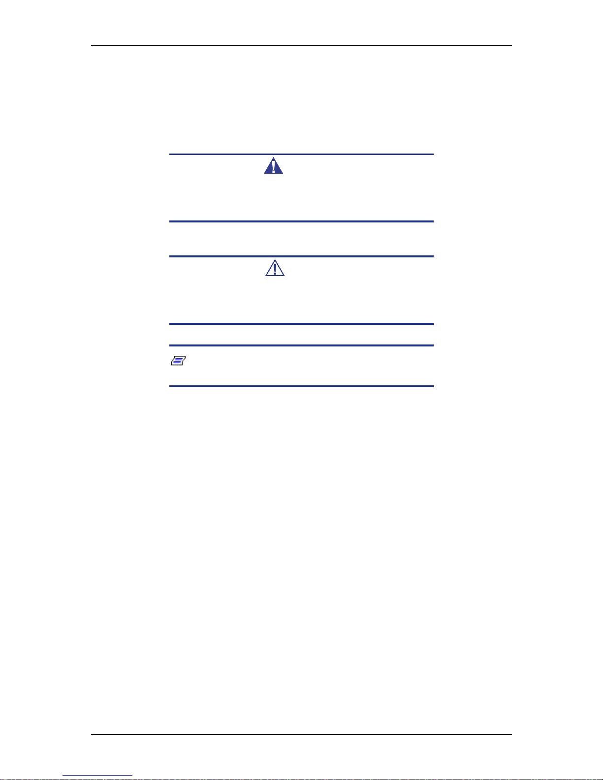
Warnings, cautions, and notes have the following meanings:
Warning
Warnings alert you to situations that could result in serious personal injury or loss of life.
Caution
Cautions indicate situations that can damage the system hardware or software.
Notes: give important information about the material being
described.
■ Names of keyboard keys are printed as they appear on the keyboard. For example,
Ctrl, Alt, or Enter.
■ Text or keystrokes that you enter appear as boldface type. For example, type
abc123 and press ENTER.
■ File names are printed in upper case letters. For example, AUTOEXEC.BAT.
Page 14
User Guide
14
www.bull.com
Safety Notices
Caution
To red uce th e risk of electric shock wh ich coul d caus e person al
injury, follow all the safety notices.
Symbols are shown in your documentation and on your
equipment to indicate safety hazards.
Regulatory Information
European Notice
Products with the CE marking comply with both the Electromagnetic Compatibility
Directive (89/336/EEC) and the Low Voltage Directive (73/23/EEC) - modified by the
Directive 93/68/EEC - issued by the Commission of the European Community.
Compliance with these directives implies conformity to the following European
Standards:
■ EN55022: Radio Frequency Interference
■ EN55024 (1998+A1:2001): Immunity characteristics
■ EN6100-3-2: Limits for harmonic current emissions
■ EN6100-3-3: Limitation of voltage fluctuation and flicker in low-voltage supply
system
■ EN60950-1 (2001): Product Safety
Warning
This is a Class A product. In domestic environment this product
may cause radio interference in which case the user may be
required to take adequate measures (EN5502 2).
If your system includes a telecommunication network board, the input/output socket is
classified as Telecommunication Network Voltage (TNV-3).
Page 15

User Guide
15
www.bull.com
USA and Canada Notice
Products with UL marking comply with the following UL standards:
■ UL 1950 (3rd edition 1998)
Products with FCC marking comply with the following FCC standards
■ FCC part 15
The model type/ref. used for UL and FCC certification can be found on the regulatory
labels stuck on your system.
The equipment has been tested and found to comply with the limits for a Class A or B
digital device, pursuant to part 15 of the FCC rules. These limits are designed to
provide reasonable protection against harmful interference when the equipment is
operated in a commercial environment. This equipment generates, uses, and can radiate
radio frequency energy, and if not installed and used in accordance with the instruction
manual, may cause harmful interference to radio communications. Operation of this
equipment in a residential area is likely to cause harmful interference, in which case the
user will be required to correct the interference at his own expense.
Modifications to the Product
CE and FCC Marking
We cannot be held responsible for modifications made by the User and the
consequences thereof, which may alter the conformity of the product with the CE or
FCC Marking.
Connections and Remote Earths
PELV (Protected Extra Low Voltage)
To ensure the extra-low voltage integrity of the equipment, only connect equipment
with mains-protected electrically-compatible circuits to the external ports.
SELV (Safety Extra Low Voltage)
Every input and output of this product is classified as Safety Extra Low Voltage.
Remote Earths
To prevent electrical shock, connect all local (individual office) systems and system
support equipment to the same electrical circuit of the building wiring. If you are
unsure, check the building wiring to avoid remote earth conditions.
Building Supply
Only connect the equipment to a building supply that is in accordance with current
wiring regulations in your country. In the U.K., those are the IEE regulations.
Page 16

User Guide
16
www.bull.com
Power Supply and Cables
Power Supply
■ The DC push-button on/off switch on the front panel does not turn off the system
AC power. +5vdc is present on the system board whenever the AC power cords are
connected between the system and an AC outlet. Before doing the procedures in
this manual, make sure that your system is powered off and unplug the AC power
cords from the back of the chassis. Failure to disconnect power before opening
your system can result in personal injury and equipment damage.
■ Under no circumstances should the user attempt to disassemble the power supply.
The power supply has no user-replaceable parts. Inside the power supply are hazardous voltages that can cause serious personal injury. A defective power supply
must be returned to your dealer.
Cables
■ In the U.S.A. and Canada, the power cord must be a UL-listed detachable power
cord (in Canada, CSA-certified), type ST or SJT, 16 AWG, 3-conductor, provided
with a moulded-on NEMA type 5-15 P plug cap at one end and a moulded-on cord
connector body at the other end. The cord length must not exceed 9 feet (2.7
meters).
■ Outside the U.S.A. and Canada, the plug must be rated for 250 VAC, 10 amp
minimum, and must display an international agency approval marking. The cord
must be suitable for use in the end-user country. Consult your de aler or the local
electrical authorities if you are unsure of the type of power cord to use in your
country. The voltage change occurs via a switch in the power supply.
■ The detachable power supply cords are intended to serve as the disconnect devices.
■ For PLUGGABLE EQUIPMENT, the socket-outlet shall be installed near the
equipment and shall be easily accessible.
■ This equipment has a 3-wire, grounded power cords. To prevent electrical hazards,
do not remove or defeat the ground prong on the power cords. Replace a power
cord if it gets damaged. Contact your dealer for an exact replacement.
Batteries
Lithium batteries can be dangerous. Improper handling of lithium batteries may result
in an explosion. Dispose of lithium batteries as required by local ordinance. Also see
“Product Disposal” on page 17
Chassis Cover Removal and Replacement
When servicing your system, make sure to replace the chassis cover and secure it with
the screws before plugging in the power cable and turning it on. The chassis cover
ensures proper airflow and cooling.
Page 17
User Guide
17
www.bull.com
Laser Compliance Statement
The optical devices are tested and certified to be compliant with International Electrotechnical Commission IEC60825-1 and European EN60825-1 standards for Class 1
laser products.
Class 1 laser products are not considered hazardous. The optical devices are designed
such that there is never human access to laser radiation above a Class 1 level during
normal operation or prescribed maintenance conditions.
The optical devices installed in your system are designed for use solely as a component
of such electronic product and therefore do not comply with the appropriate
requirements of Code of Federal Regulation Sec. 1040.10 and Sec. 1040.11 for
COMPLETE laser products
Warning - Hazardous Voltage!
Hazardous voltage is present inside your system when it is connected to an AC supply
even when the system’s power switch is off. Exposure to Hazardous Voltage could
cause personal injury. To reduce the risk of electric shock which could cause personal
injury, follow all safety notices. The symbols shown are used in your documentation
and on your equipment to indicate safety hazards.
Warning -Avoid Electrostatic Discharge!
Circuit cards and integrated circuits can be easily damaged by static electricity. To
reduce risk of damage, store them in protective packaging whenever they are not
installed in your system.
Before you install or remove memory modules, video memory, disk drives, circuit
cards or other devices, protect them from static electricity. To do so, make sure your
system’s power switch is OFF. Then, unplug the system’s AC power cord(s). Wear an
anti-static wrist strap (available at electronic supplies stores) to handle the device you
want to install. Be sure to connect the wrist strap to an unpainted metal portion of the
system chassis.
As an alternative, you can dissipate electrostatic buildup by touching an unpainted
metal portion of the system chassis with one hand. Handle the device you are installing
with the other hand, and maintain continuous contact with the unpainted portion of the
chassis until it is installed in the system.
Product Disposal
The Wa ste Electrical and Electronic Equipment (WEEE) Directive
requires that used electrical and electronic products must be disposed of
separately from normal household waste in order to promote reuse,
recycling and other forms of recovery and to reduce the quantity of waste
to be eliminated with a view to reducing landfill. WEEE includes
accessories such as keyboard, mouse, remote control, speakers, etc. When you dispose
of such products, please follow the agreement made between you and us and/or your
distributor.
Page 18

User Guide
18
www.bull.com
System Features
This system is a highly flexible and reliable server designed to offer the highest levels
of performance for the price range.
Its main features are:
■ The Intel® 3210 chipset.
■ The Intel® processor, either an Intel® Pentium® dual-core processor, a Dual-Core
Intel® Xeon® processor, or a Quad-Core Intel® Xeon® processor.
■ The RAID technology, offering support for various RAID levels on Microsoft®
Windows® and Linux operating systems.
■ Depending on your configuration:
- A tower chassis that can also easily be installed into a standard EIA 19-inch
rack cabinet (NovaScale T810 E1, NovaScale T830 E1).
- A rack chassis ( NovaScale R410 E1).
To get comfortable with your computer, we recommend you read this user guide. Keep
it in a safe place for future reference.
Page 19

User Guide
19
www.bull.com
Related Documents
In the ExpressBuilder disc in which you found this User’s Guide, you can also find
several other documents relevant to your system, options and accessories.
Some printed documents may also have been shipped with your system.
We recommend you read these additional documents as it becomes necessary when
setting up, using or upgrading your system.
Page 20
User Guide
20
www.bull.com
NovaScale T810 E1 System Chassis Features
Front View
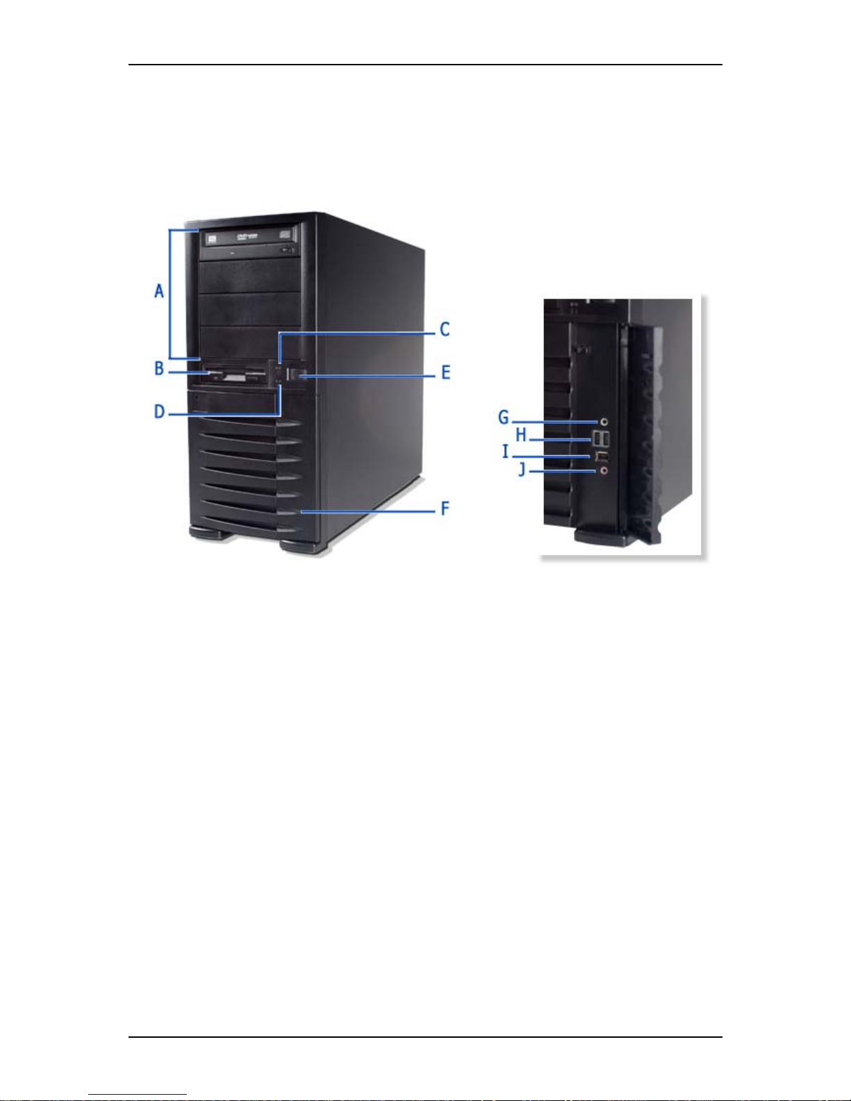
The following figure shows the location of the front system features
Figure 1: Front View
A 5.2 5-inch bays F F ro nt door
Four 5.25-inch bays, one of which may include a
DVD-ROM drive or DVD Writer drive.
Open the front door to access the headphone
connector, the stereo microphone in connector
and the USB ports.
B 3.5-inch bay G Headphone connector
One 3.5-inch bay that may include a 3.5-inch
floppy disk drive.
Not functional.
CStatus lamp HUSB ports
Indicates whether the computer is on or off. A
steady green lamp indicates the computer is on.
The lamp lights amber when the computer is in
stand-by mode.
Two Universal Serial Bus (USB) ports allow
you to connect USB-equipped peripheral
devices such as printers.
These connectors are not functional when an
additional USB tape drive is installed.
D Device lamp I IEEE port
Lights up when a hard disk drive or an optical drive
is active, reading or retrieving data.
Not functional.
E Power button J Stereo microphone in connector
Press this switch to turn on/off the power. Refer to
the ‘Powering On your System’, ‘Powering Off your
System’ and ‘Forcing a Power Shutdown’ sections
hereafter for details.
Not functional.
Front View Detail
Page 21
User Guide
21
www.bull.com
NovaScale T810 E1 Rear View
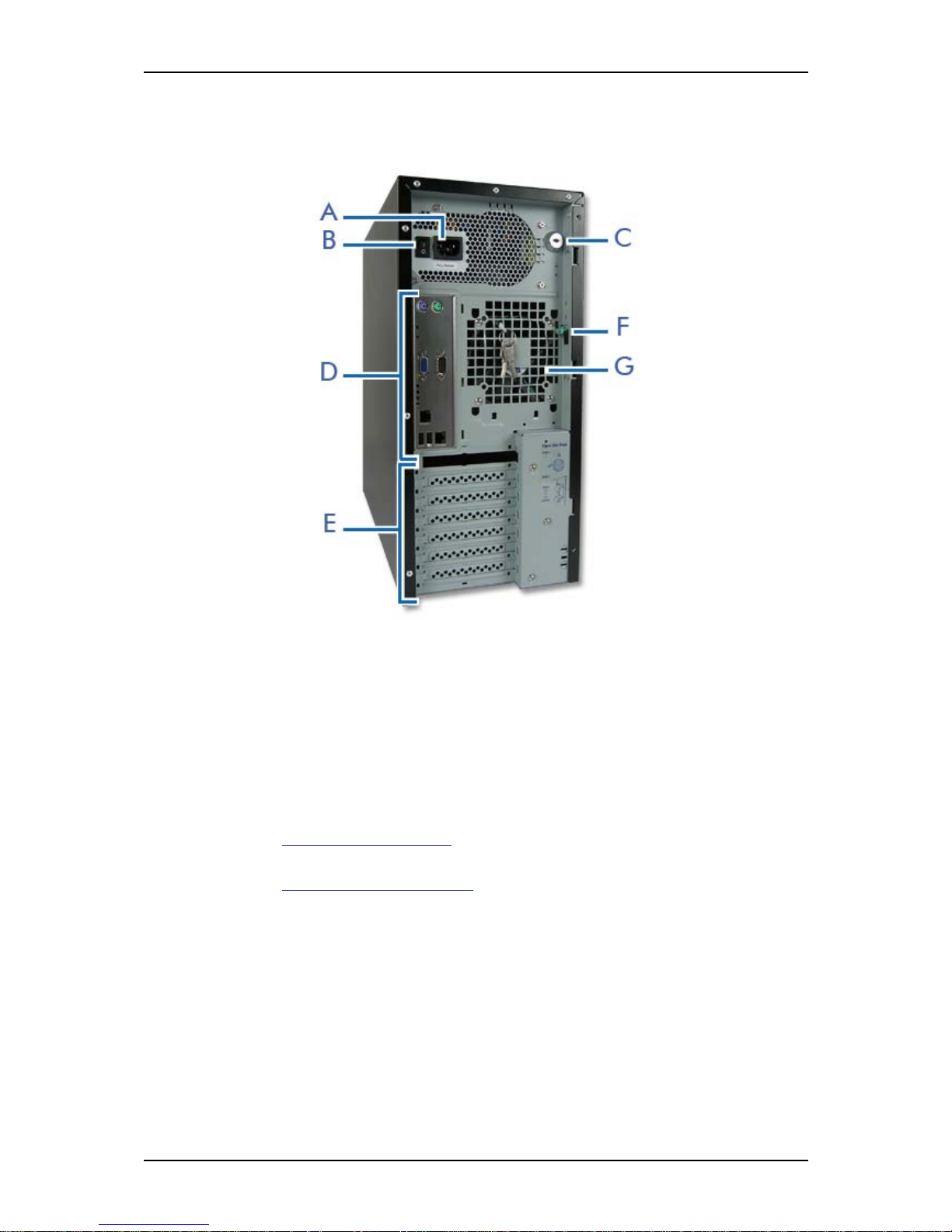
Figure 2: Rear View
A AC power connector
Connect the power cord to this socket.
B Power switch
CKey lock
Security feature that allows you to open the right side door.
D Connectors
Refer to
“Motherboard” on page 34
E Expansion boards slots
Refer to “Expansion Slots” on page 45
F Side cover latch
Push the latch up to enable the right side door opening.
G Venting holes
Keep the area near the venting holes clear for proper ventilation.
Page 22

User Guide
22
www.bull.com
NovaScale T810 E1 Status Indicators
This section explains the indication and meanings of the server lamps.
Power Lamp
■ Lights green to indicate normal operation with the server powered on.
■ Remains off when the server is powered off.
■ Blinks green when the server is in a power-saving mode.
Access Lamp
Lights amber when one of the drives is being accessed.
Caution
To indicate the acces s states of the built-in hard disk drives
when an optional board (e.g. disk mirroring controller or disk
array controller) is installed, connect the LED cable provided
with the server to the LED connector on the motherboard and
the optional board.
LAN Connector Lamps
Refer to the back panel description for more details. See “Back Panel Connectors” on
page 39.
Page 23
User Guide
23
www.bull.com
NovaScale T810 E1 Internal View
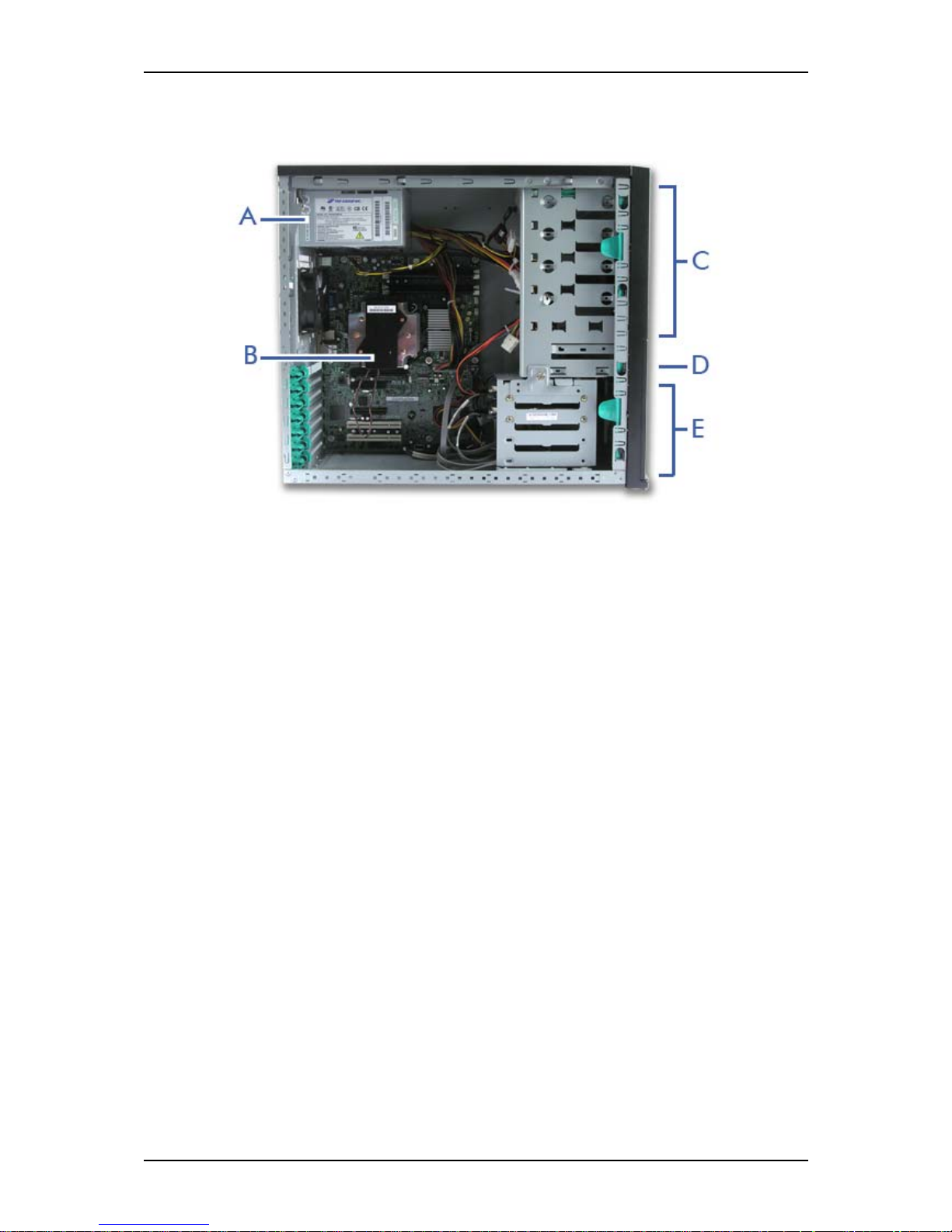
Figure 3: Internal View
A Power supply slot
B Motherboard
C 5.25-inch devices slots
D 3.5-inch devices slot
E Hard disk drives slots
Page 24
User Guide
24
www.bull.com
NovaScale R410 E1 System Chassis Features
Front View
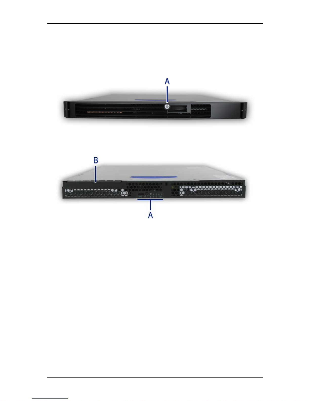
The following figure shows the location of the front system features.
Figure 4: Front View (with Front Bezel)
A: Key Lock
Figure 5: Front View (without Front Bezel)
A: Control Panel
B: Optical Disc Drive Bay
Page 25
User Guide
25
www.bull.com
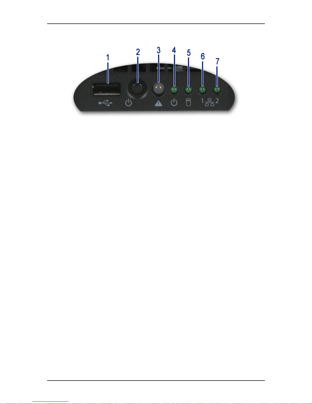
Figure 6: Control Panel (Front View detail)
1. USB Port.
One Universal Serial Bus (USB) port allows you to connect USB-equipped
peripheral devices such as printers.
2. Power button.
Press this switch to turn on/off the power. Refer to the ‘Powering On your
System’, ‘Powering Off your System’ and ‘Forcing a Power Shutdown’
sections hereafter for details.
3. Status lamp.
- Solid green indicates that the system is ready.
- Blinking green indicates that either the processor or a memory slot is disabled.
- Solid amber indicates a critical temperature, a voltage fault, or a missing
CPU/terminator.
- Blinking amber indicates a power fault, fan fault, or a non-critical temperature or voltage fault.
- No light indicates a fatal error during POST.
4. Power/Sleep lamp.
Indicates whether the computer is on or off.
A steady green lamp indicates the system is on or in sleep state S0. An unlit
lamp means that the system is in sleep state S5.
5. Disk Access lamp.
Lights up when a hard disk drive is active, reading or retrieving data.
6. Network Interface Card (NIC) 1 LED.
Shows the Local Area Network (LAN) 1 access status.
7. Network Interface Card (NIC) 2 LED.
Shows the Local Area Network (LAN) 2 access status.
Page 26
User Guide
26
www.bull.com
NovaScale R410 E1 Rear View
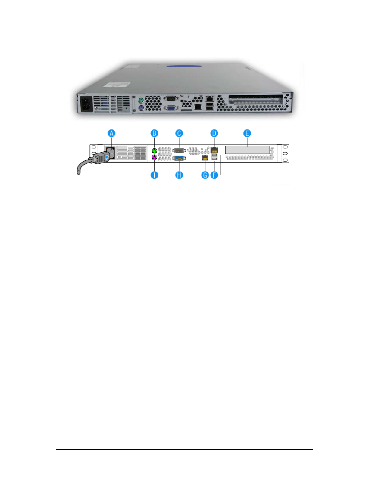
Figure 7: Rear View
A AC power connector
Connect the power cord to this socket.
BMouse Port
Connect the mouse included with the system.
C Serial Port A
Connect any peripheral with a serial interface.
D Network Interface Card (NIC) 1
Connect the system to a LAN allowing the following transfer speeds: 1000BASE-T/
100BASE-TX/10BASE-T.
E PCI Add-in card slot
Additional ports are available if an optional card is installed.
F USB Ports
Connect any peripherals with an USB interface.
G Network Interface Card (NIC) 2
Connect the system to a LAN allowing the following transfer speeds: 1000BASE-T/
100BASE-TX/10BASE-T.
HVideo
Connect a compatible monitor.
IKeyboard
Connect the keyboard included with the system.
Page 27
User Guide
27
www.bull.com
NovaScale R410 E1 Internal View
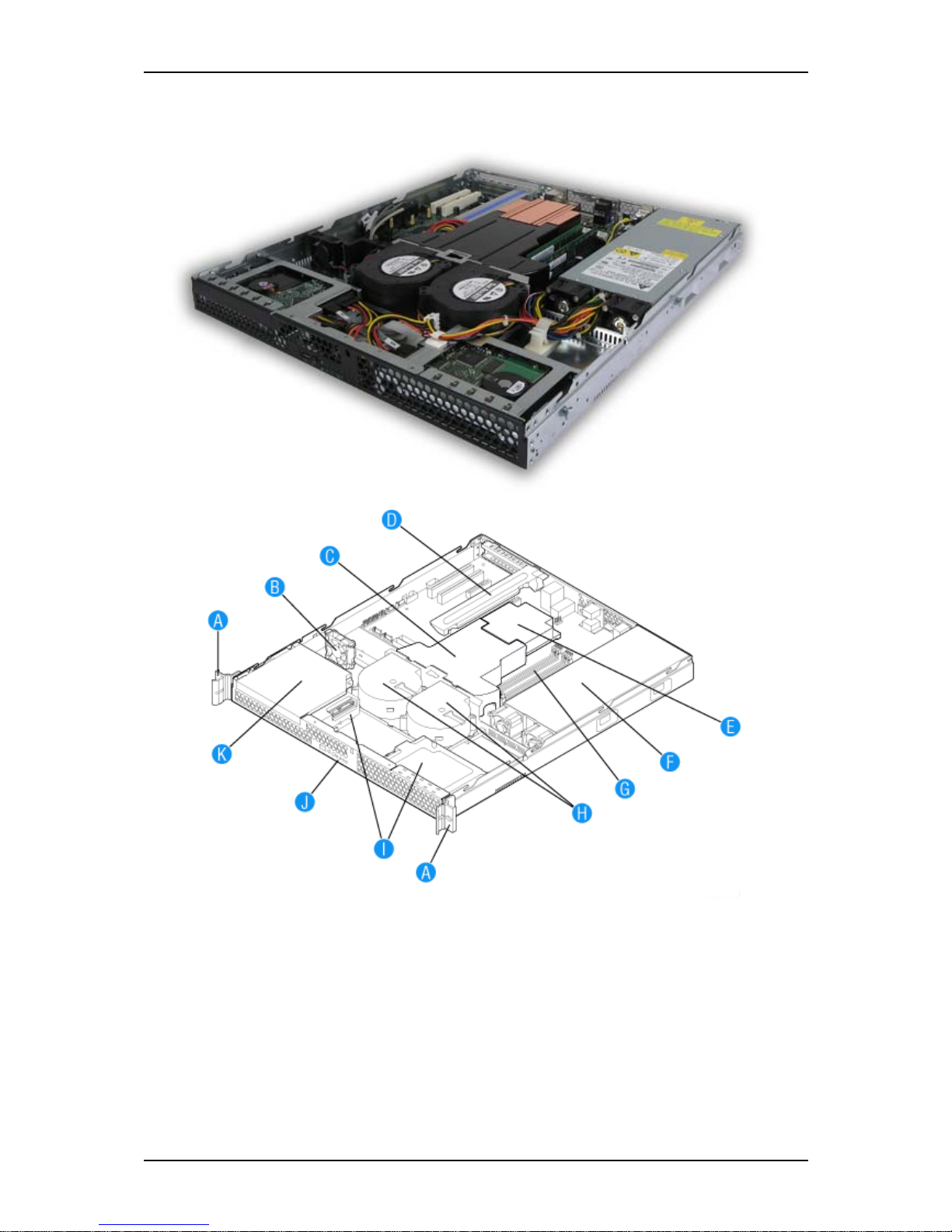
Figure 8: Internal View
A. Rack Handles (two) G. System Memory DIMM Sockets
B. PCI Cooling Fan H. System Blower Fans (two)
C. Processor Air Duct I. Hard Drive Brackets (two)
D. PCI Add-in Card Bracket J. Control Panel
E. Processor and Heat Sink K. Slimline Optical Drive Bay
F. Po we r S up p l y
Page 28
User Guide
28
www.bull.com
NovaScale T830 E1 System Chassis Features
Front View with Front Bezel
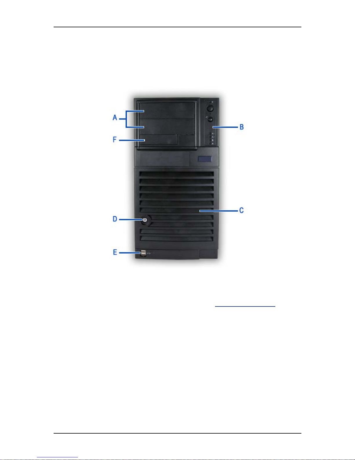
The following figure shows the location of the front system features
Figure 9: Front Viewl
A 5.25-inch bays B Front panel
Two 5.25-inch bays, one of which may include a
tape backup unit or optical disc drive.
Refer to
“Front Panel” on page 31 for more
information on the buttons and LEDs.
C Hard Disks cage D Drives bay access door and lock
Depending on your configuration, this cage either
contains SATA or SAS drives, which can be fixed
or hot-swappable.
Security feature that allows you to open the
right side door.
E USB ports F 3.5-inch bay
One 3.5-inch bay, that may be fitted with a
floppy disk drive (optional).
Page 29
User Guide
29
www.bull.com
Front View without Front Bezel
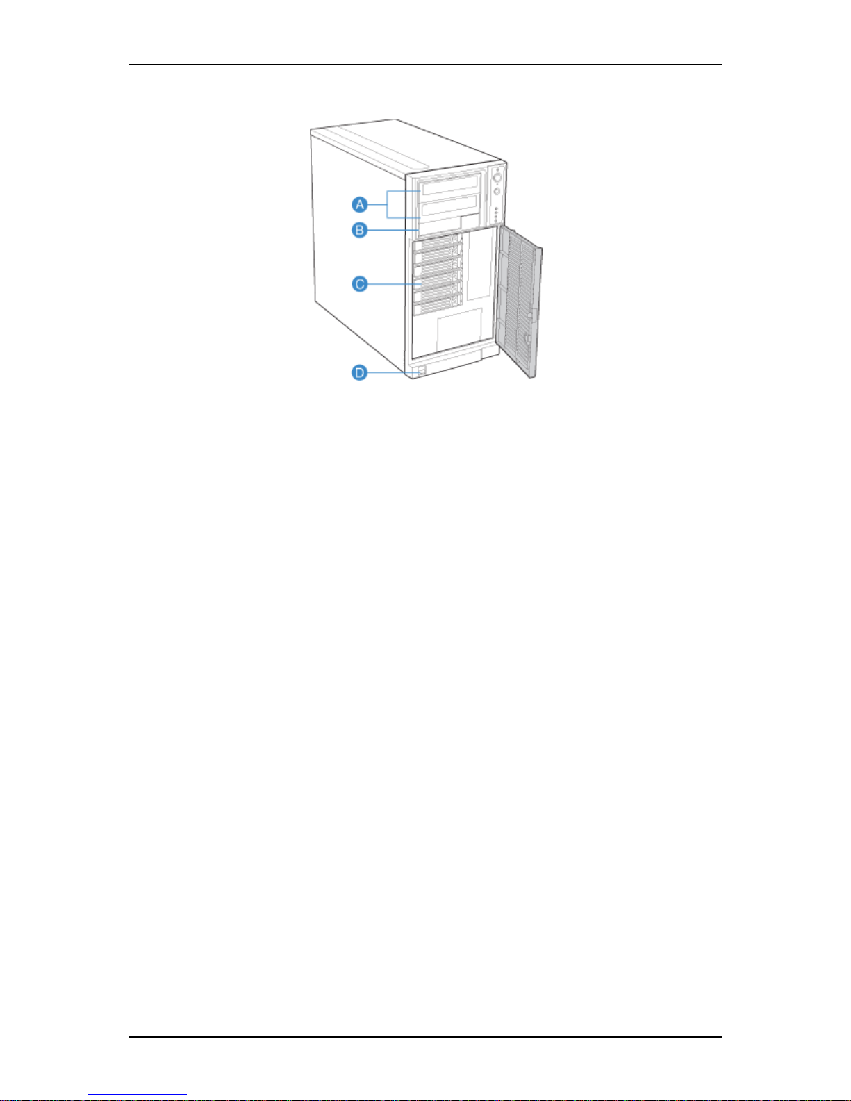
Figure 10: Front view without front bezel
A 5.2 5-i nc h ba y s B 3.5-inch bay
Two 5.25-inch bays, one of which may include a
tape backup unit, CD-ROM drive, DVD-ROM
drive, DVD-RW drive or COMBO DVD-ROM CDRW drive.
One 3.5-inch bay, that may be fitted with a
floppy disk drive (optional).
C Hard Disks cage D Front panel USB ports
Depending on your configuration, this cage either
contains hot-swappable SATA or SAS drives.
Page 30
User Guide
30
www.bull.com
NovaScale T830 E1 Rear View
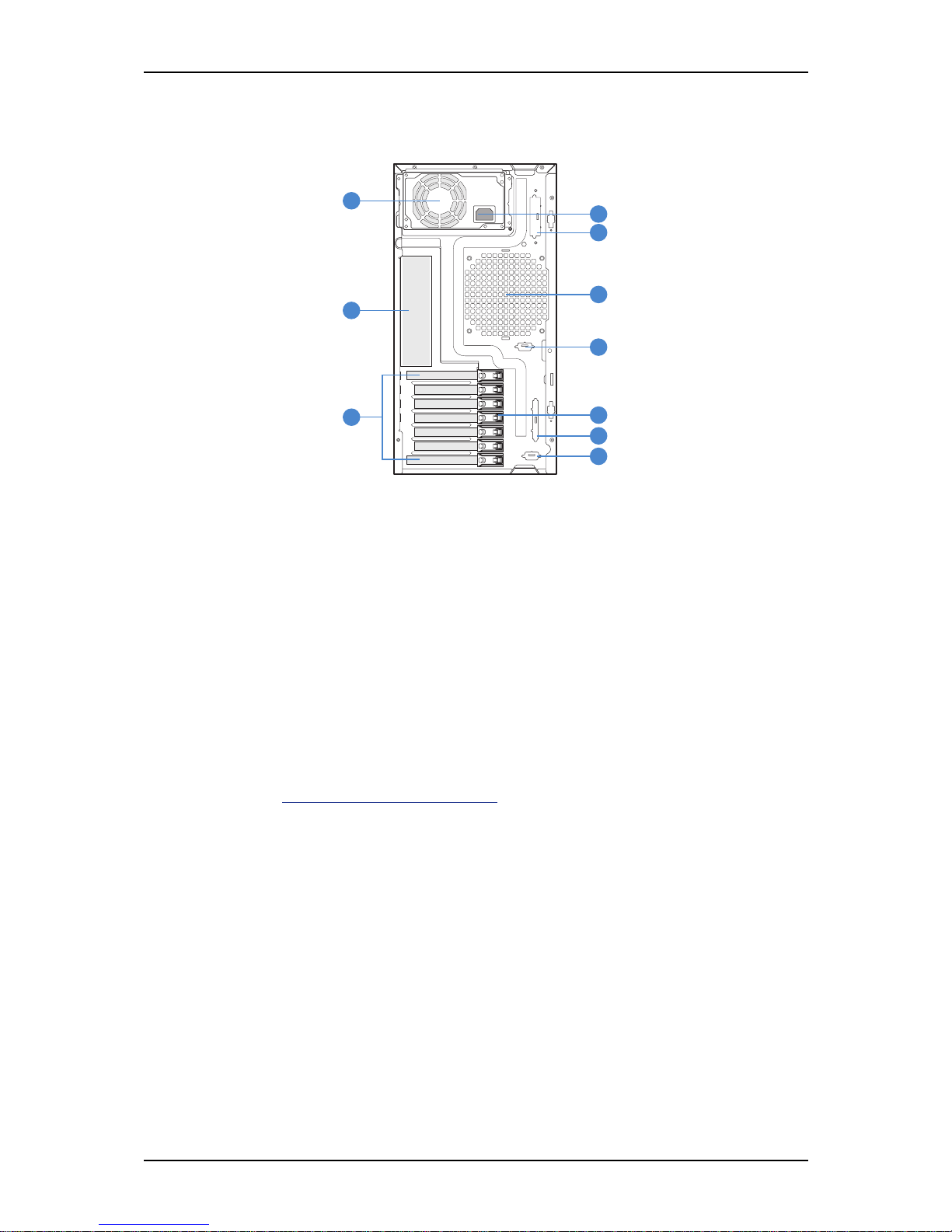
Figure 11: Rear View
A Power supply bay
Depending on your configuration, it is fitted with a fixed power supply (shown in the picture),
or one with hot-swappable power modules.
B AC power connector
Connect the power cord to this socket.
C Alternate SCSI knockout
D System fan
Keep the area near the venting holes clear for proper ventilation.
E Connectors
Refer to “
Back Panel Connectors” on page 39 for details.
F Alternate Serial B knockout
G Expansion boards slots
Refer to the ‘Expansion Boards Slots’ section hererafter for details
H PCI Tool-less card retention mechanism
I External SCSI knockout
J Serial B kn ockout
TP00880
B
D
H
A
E
G
C
F
I
J
Page 31
User Guide
31
www.bull.com
NovaScale T830 E1 Status Indicators
This section explains the indication and meanings of the system lamps located on the
front and back panels of your system.
Front Panel
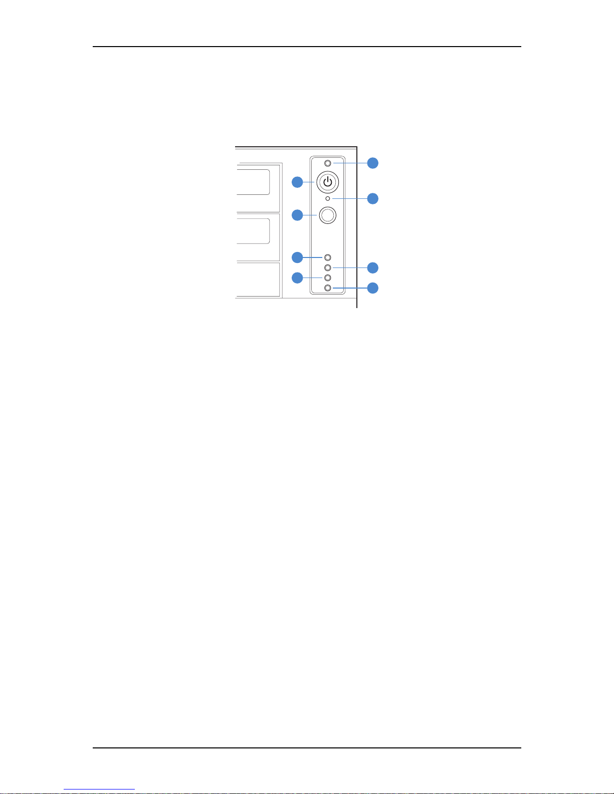
Figure 12: Front panel (front view detail)
A Power/Sleep LED B Power/Sleep LED
Continuous green light indicates the system has
power applied to it.
Continuous amber light indicates the system is in
S1 Sleep state.
No light indicates the power is off / or the system is
in S4 Sleep state.
Powers the system off or on.
C NMI Button D Reset Button
Used to force system halt and dump memory
contents to screen or file.
Reboots and initializes the system.
E/F NIC 1 Activity LED / NIC 2 Activity LED G Hard Drive Activity LED
Continuous green light indicates a link between
system and network.
Blinking green light indicates network activity.
No light indicates the NIC is disconnected.
Random blinking green light indicates hard
drive activity (SCSI or SAS/SATA).
Continous amber light indicates a hard drive
fault.
No light indicates no hard disk drive activity.
HStatus LED
Solid green indicates system ready.
Blinking green indicates processor or memory
disabled.
Solid amber indicates a critical temperature or
voltage fault, or a missing CPU/terminator.
Blinking amber indicates a power fault, fan fault, or
a non-critical temperature or voltage fault.
No light indicates a fatal error during POST.
TP02346
A
C
F
H
B
D
E
G
Page 32

User Guide
32
www.bull.com
Back Panel
Network Interface Card (NIC) Ports Activity Lamps
Refer to the back panel description for more details. See “Back Panel Connectors” on
page 39.
Power Supply LEDs (Hot-Swap Power Supply Only)
Please refer to “Power Supply LEDs” on page 109 for more information.
Diagnostic LEDs
Please refer to “Diagnostic LEDs” on page 284 for more information.
Page 33
User Guide
33
www.bull.com
NovaScale T830 E1 Internal View
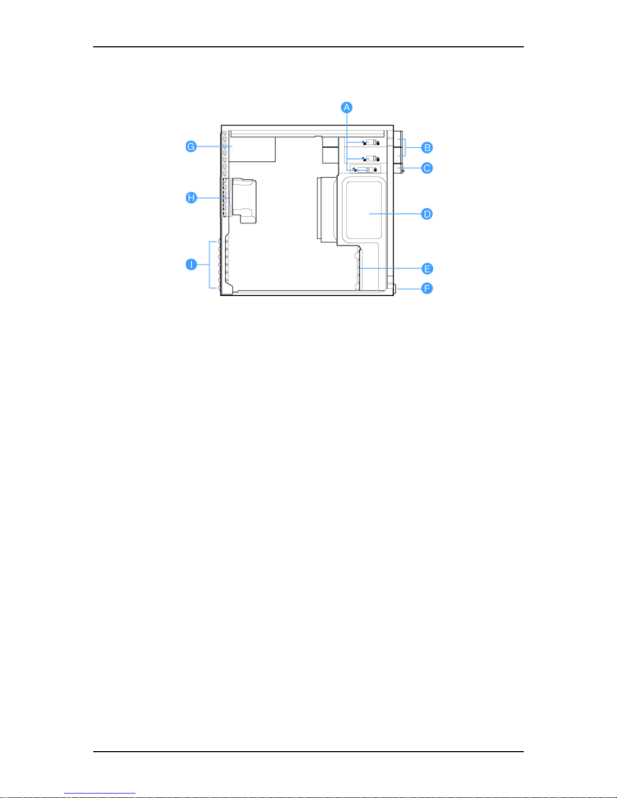
Figure 13: Internal View
A To ol-less Device Bay Locks
B 5.25-in Device Bays
C 3.5-in Device Bay
D Hard Disk Drive Bay
E Drive Cage Retenti on Mechanism
F PCI Add-in Card Guide
G Power Supply
H Fan Duct / System Fan Assembly
I Rear Tool-less PCI Retention Mechanisms
Page 34
User Guide
34
www.bull.com
Motherboard
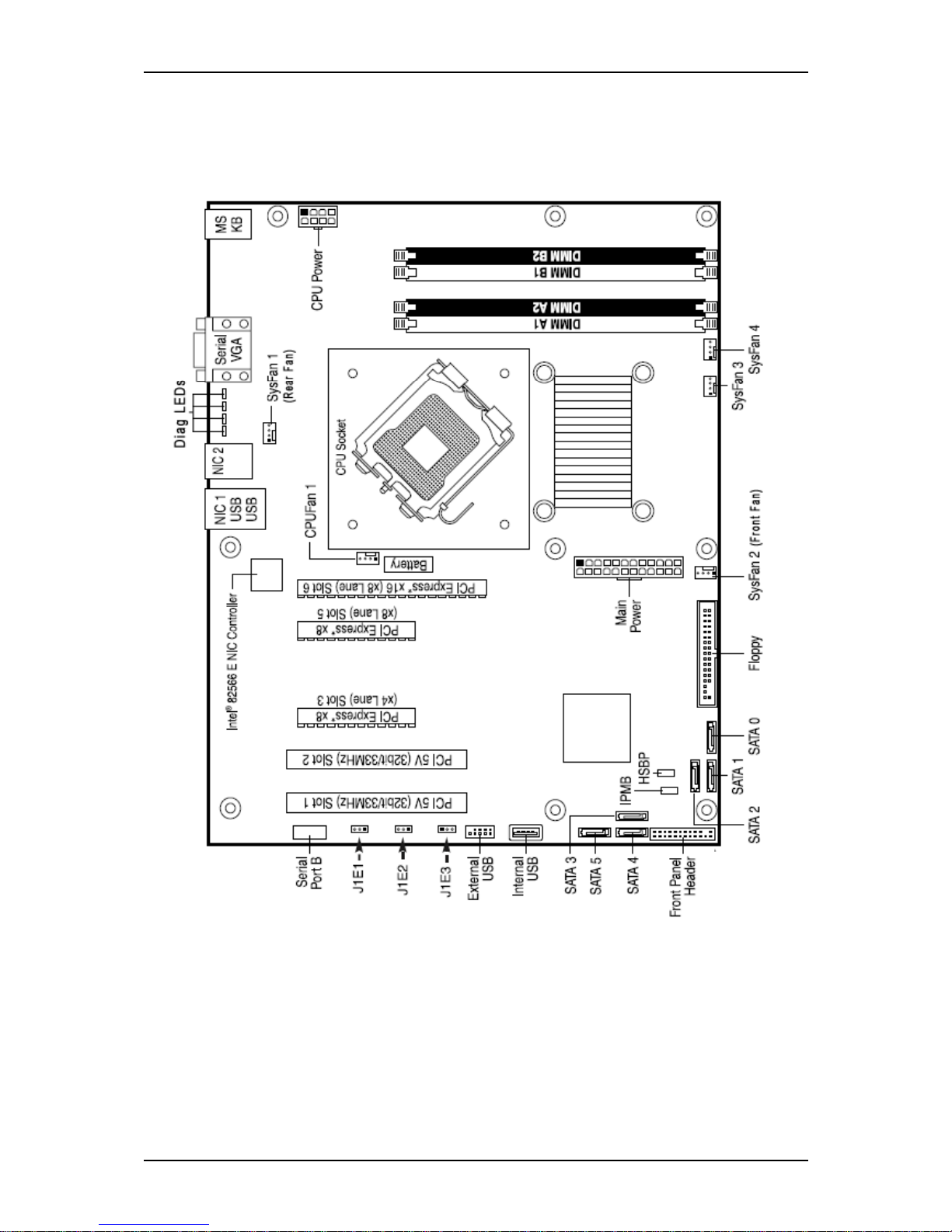
Motherboard Layout
Figure 14: Motherboard Layout
Page 35
User Guide
35
www.bull.com
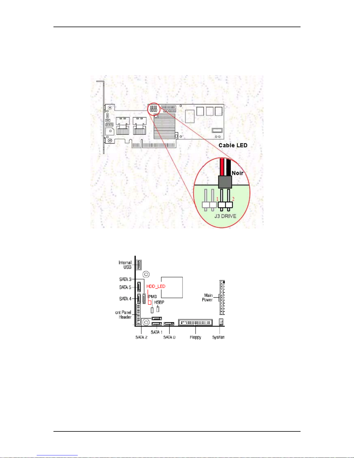
Connecting the LSI 8708EM2 SAS/SATA RAID Controller (if applicable)
If you purchased the LSI 8708EM2 separately, we recommend you also connect the
included LED cable to the motherboard. This will ensure that the HDD access LED on
the Front Panel lights when there is hard disk drive access.
Figure 15: HDD header on the LSI 8708EM2
Figure 16: HDD header on the motherboard
Page 36
User Guide
36
www.bull.com
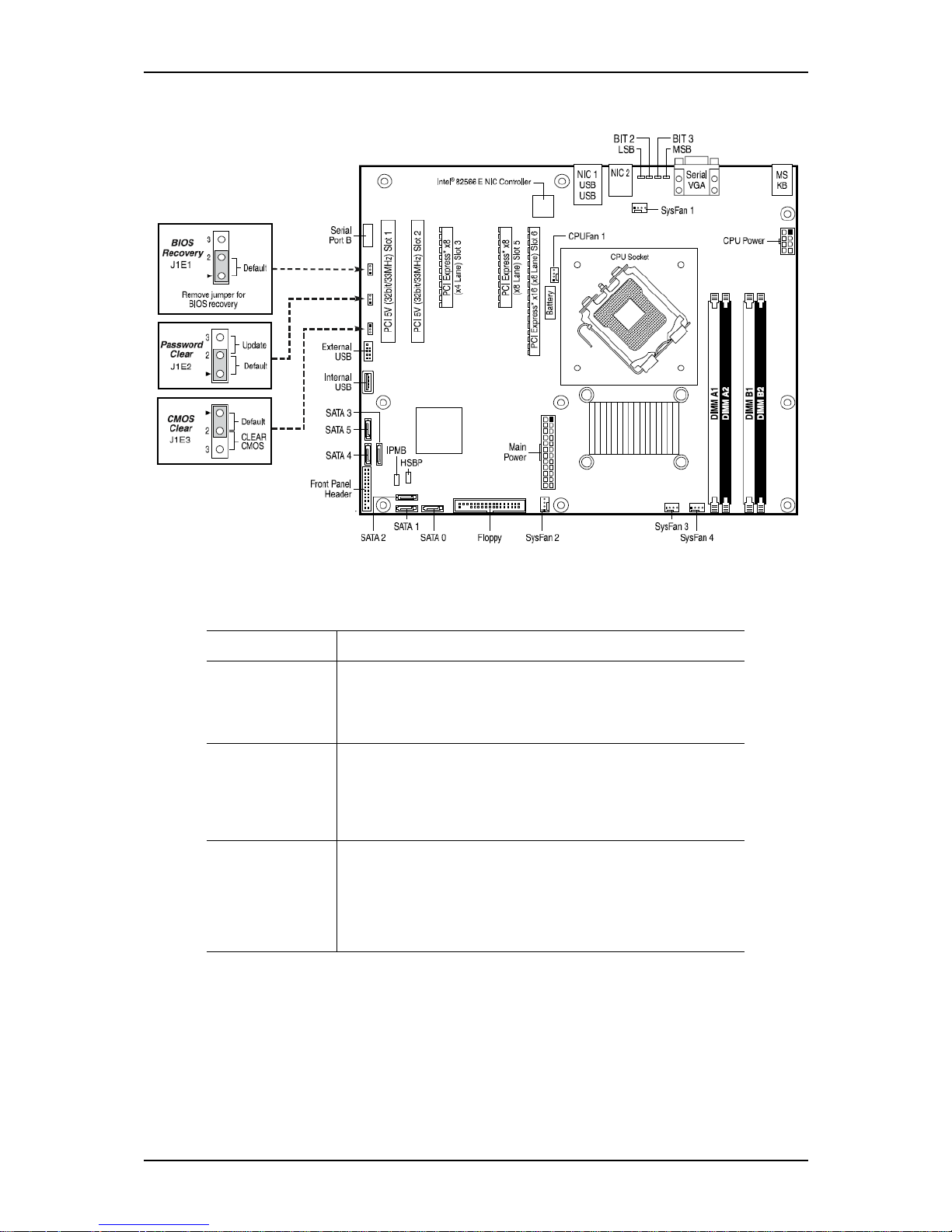
Motherboard Jumpers
Figure 17: Motherboard Jumpers
Table 1: Motherboard Jumpers Description
Jumper Name Jumper Purpose
RCRY MODE In the normal position (pins 1-2), allows normal system operation
with correct BIOS settings. The system will POST normally.
Remove the jumper to recover from a corrupted BIOS. A bootable
media with a valid BIOS ROM required.
PASSWD CLR In the normal position (pins 1-2), allows normal system operation
with current password settings. The system will POST normally.
In the clear position (pins 2-3), the system clears the password
settings following the POST. If necessary, reset a password in the
BIOS Setup utility.
CMOS CLR In the normal position (pins 1-2), allows normal system operation
with correct BIOS settings. The system will POST normally.
In the clear position (pins 2-3), the system initiates a clearing of the
NVRAM following the POST. A system message confirms that the
operation was successful. This setting enforces the default BIOS
settings, which can be changed in the BIOS Setup utility.
Page 37
User Guide
37
www.bull.com
Clearing the CMOS
If you are not able to access the BIOS setup screens, the CMOS Clear jumper will need
to be used to reset the configuration RAM.
1. Power down the system and disconnect the AC power.
2. Open the server.
3. Move the jumper (CMOS CLR) from the normal operation position (pins 1 and
2) to pins 2 and 3 (Clear CMOS position).
4. Reconnect the AC power, power up the system.
5. When the system begins beeping, power it down and disconnect the AC power.
6. Replace the jumper on pins 1 and 2.
7. Close the server chassis.
8. Reconnect the AC power and power up the system.
Recovering the BIOS
This jumper is used to select the BIOS image from which the system will boot.
Note: for more information on the BIOS Update process,
please refer to “Updating the BIOS” on page 303.
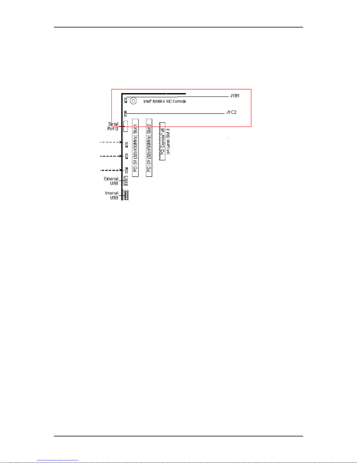
BMC jumpers
■ J1B1 = IBMC Force Update Mode
Jumper Position:
1-2: Normal (Default)
2-3: Force Update Mode
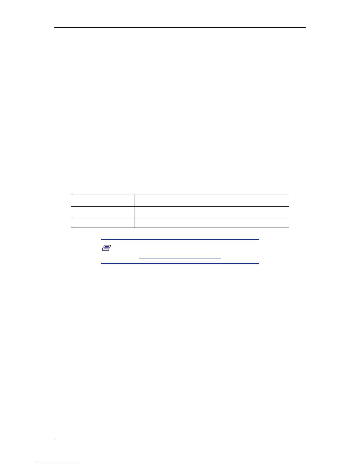
Table 2: BIOS Recovery Jumper Descriptions
Pins Jumper Purpose
1-2 System is configured for normal operation (Default).
No jumper Allows the BIOS recovery.
Page 38
User Guide
38
www.bull.com
■ J1C2 = IBMC Boot Block Write Protection
Jumper Position:
1-2: Unprotect
2-3: Protected (Default)
Page 39
User Guide
39
www.bull.com
Back Panel Connectors
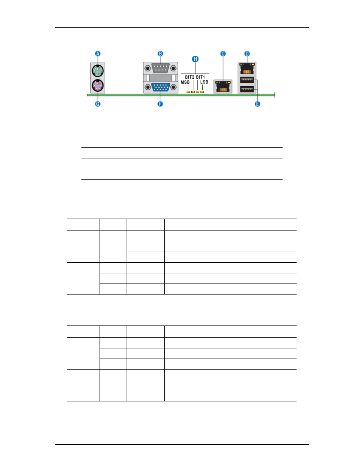
Figure 18: Back Panel Connectors
The NIC (Network Interface Card) LEDs at the right and left of each NIC provide the
following information.
.
Table 3: Back Panel Connectors
A: Mouse B: Serial Port A
C: NIC 2 (10/100/1000 Mb) D: NIC 1 (10/100/1000 Mb)
E: USB 0-1 F: Video
G: Keyboard H: Diagnostic LEDs
Table 4: NIC1 LED Descriptions
LED Color LED State Description
Left Green Off No network connection
On Network connection in place
Blinking Transmit/receive activity
Right N/A Off 10 Mbps connection (if left LED is on or blinking)
Green On 100 Mbps connection
Yellow On 1000 Mbps connection
Table 5: NIC2 LED Descriptions
LED Color LED State Description
Left N/A Off 10 Mbps connection (if left LED is on or blinking)
Green On 100 Mbps connection
Yellow On 1000 Mbps connection
Right Green Off No network connection
On Network connection in place
Blinking Transmit/receive activity
Page 40

User Guide
40
www.bull.com
Memory Configuration
The server board provides four DIMM sockets across two channels, Channel A and
Channel B.
- Channel A consists of DIMM sockets A1 and A2.
- Channel B consists of DIMM sockets B1 and B2.
DIMM Population Rules
To ensure the dual channel operating mode, install either:
■ two modules, in the slots DIMM_A1 and DIMM_B1,
■ or four modules.
Note:
■ The installation of three modules is not supported.
■ The motherboard BIOS supports single DIMM mode opera-
tion although this is generally not recommended for “performance” applications. This configuration is only supported
with a 1 GB DIMM installed in DIMM slot A1.
Use DIMMs of identical size and speed.
Supported memory
DIMMs must meet the following requirements:
- Use only DIMMs with DDR2 DRAM technology.
- Use only DDR2-800 stacked DIMM modules.
Page 41

User Guide
41
www.bull.com
BMC Controller
The Integrated Baseboard Management Controller (iBMC) is a highly integrated
single-chip solution, which contains the following integrated subsystems and features.
Server Class Super I/O functionality includes
- Keyboard style/BT interface for BMC support
- Two Fully Functional Serial Ports, compatible with the 16C550
- Serial IRQ Support
- SMI/SCI/PME Support
- ACPI Compliant
- Up to 16 Shared GPIO ports
- Programmable Wake-up Event Support
- Plug and Play Register Set
- Power Supply Control
- Watchdog timer compliant with Microsoft* SHDG
- LPC to SPI bridge for system BIOS support
- Real Time Clock module with the external RTC interface
Baseboard Management Controller
- IPMI 2.0 Compliant
- Integrated 250Mhz 32-bit ARM9 processor
- Six I2C SMBus Modules with Master-Slave support
- Two independent 10/100 Ethernet Controllers with RMII support
- LPC Master interface for non-volatile code storage
- SPI Flash interface
- Three UART for ICMB support
- DDR-II 16bit up to 667 MHz memory interface
- Sixteen Mailbox Registers for communication between the host and the BMC
- Watchdog timer
- Three General Purpose Timers
- Dedicated Real Time Clock for BMC
- Up to 16 direct and 64 Serial GPIO ports
- Ability to maintain text and graphics controller history
- 12 10-bit Analog to Digital Converters
Page 42

User Guide
42
www.bull.com
- Three Diode Inputs for Temperature measurements
- Eight Fan Tach Inputs
- Four Pulse Width Modulators (PWM)
- Chassis Intrusion Logic with battery backed general purpose register
- LED support with programmable blink rate control
- Programmable IO Port snooping, can be used to snoop on Port 80h
- Unique Chip ID for each part, burned at the time production testing
- Hardware 32-bit Random Number generator
-JTAG Master interface
- On-Chip Test Infrastructure for testing BMC firmware
Remote KVMS Features
- USB 2.0 interface for Keyboard, Mouse and Remote storage such as CD/DVD
ROM and floppy
- USB 1.1 interface for PS2 to USB bridging, remote Keyboard and Mouse
- Hardware Based Video Compression and Redirection Logic
- Supports both text and Graphics redirection
- Hardware assisted Video redirection using the Frame Processing Engine
- Direct interface to the Integrated Graphics Controller registers and Frame buffer
- Hardware based encryption engine
Graphics Controller Subsystem
- Integrated Matrix Graphics Core
- 2D Hardware Graphics Acceleration
- DDR-2 memory interface supports up to 128Mbytes of memory
- Supports all display resolutions up to 1600 x 1200 16bpp @ 75Hz
- High speed Integrated 24-bit RAMDAC
- Single lane PCI Express* host interface
Page 43

User Guide
43
www.bull.com
St andard Features
Processor
The system board can accommodate one of the following:
- an Intel® Pentium® dual-core processor,
- a Dual-Core Intel® Xeon® processor,
- or a Quad-Core Intel® Xeon® processor.
Memory
The system board provides four 240-pins DIMM slots each supporting DDR2 800 ECC
memory. You may install a minimum of 1 GB and as much as 8 GB (4 x 2 GB).
Your system supports dual-channel memory architecture. Refer to “
Memory
Configuration” on page 40 for details.
Video
The motherboard features an integrated VGA Graphics Accelerator Matrox® G200e.
Network Controller
Note: To ensure EMC product regulation compliance, the
system must be used with a shielded STP/FTP LAN cable.
The motherboard features two controllers for 10/100/1000 Mbit/s Ethernet LAN
connectivity:
-Intel
®
82566DM dual port controller.
-Intel® 82541PI port controller (Pro/1000 MT).
RAID Support
The motherboard features one onboard controller providing two RAID ROM support
for S-ATA configurations.
■ Intel RAID ROM
- RAID0, RAID1, RAID5, and RAID10 support.
- Microsoft Windows support.
- Set-up with the Intel Matrix Storage Manager configuration utility. Refer to
“RAID Configuration using Intel Matrix Storage Manager” on page 122.
Page 44

User Guide
44
www.bull.com
■ LSI RAID ROM
- RAID0, RAID1 and RAID10 support.
- For Linux applications.
- Set-up with the Intel Embedded RAID configuration utility. Refer to “RAID
Configuration using the Intel® Embedded Server RAID BIOS Configuration
Utility” on page 125.
Refer to the “Advanced Menu” on page 291 for more information on how to select the
controller that will be active in your system.
ACPI
The motherboard supports the Advanced Configuration and Power Interface (ACPI) as
defined by the ACPI 2.0 specifications. An ACPI aware operating system can put the
system into a state where the hard drives spin down, the system fans stop, and all
processing is halted. However, the power supply will still be on and the processors will
still be dissipating some power, so the power supply fans will still run.
The system board supports sleep states s0, s1, s4, and s5:
■ s0: Normal running state.
■ s1: Processor sleep state. No context will be lost in this state and the processor
caches will maintain coherency.
■ s4: Hibernate. Your working environment is Saved To Disk
■ s5: Shutdown.
Keyboard and Mouse
The keyboard/mouse controller is PS/2-compatible.
Page 45

User Guide
45
www.bull.com
NovaScale T810 E1 Specific Features
Power Supply
The system contains one auto-sensing 400-watt power supply at an operating frequency
of 50/60 Hz.
The power supply is designed to comply with existing emission standards and provide
sufficient power for a fully loaded system configuration.
Peripheral Bays
The system supports a variety of standard PC AT-compatible peripheral devices. The
chassis includes these peripheral bays:
■ One 3.5-inch file bay to install a 3.5-inch floppy disk drive (supports 1.44MB
floppy disk media) or an optional file device.
■ Four 5.25-inch file bays to install half-height 5.25-inch peripheral devices such as
optional tape drives (An optical drive is factory-installed).
■ The hard disk drive bays to install up to four SATA2 or SAS hard disk drives.
Expansion Slots
■ Two 32-bit/33MHz, 3V PCI connectors.
■ One x8 PCI Express connector (x4 lane).
■ One physical x8 PCI Express connector (x8 lane).
■ One physical x16 PCI Express connector (x8 lane).
Page 46
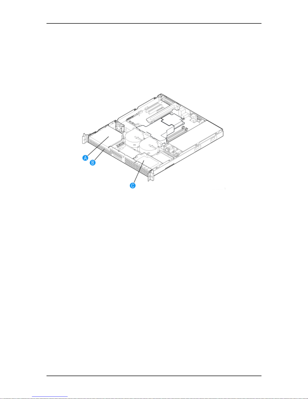
User Guide
46
www.bull.com
NovaScale R410 E1 Specific Features
Peripheral Bays
The system supports a variety of standard PC AT-compatible peripheral devices. The
chassis includes these peripheral bays:
■ One slimline 5.25-inch file bay for the installation of an optical drive.
■ Two hard disk drive bays for the installation of SATA drives.
Figure 19: Peripheral Bays
A: Slimline Optical Drive Bay
B: Hard Disk Drive Bay HDD0
C: Hard Disk Drive Bay HDD1
Expansion Slot
The system provides one full-length x16 PCI Express riser board (x8 lane).
RAID Support
Although your motherboard includes support for several RAID levels, only the RAID
levels 0 and 1 are available on your system (limited to 2 hard disk drives).
Page 47
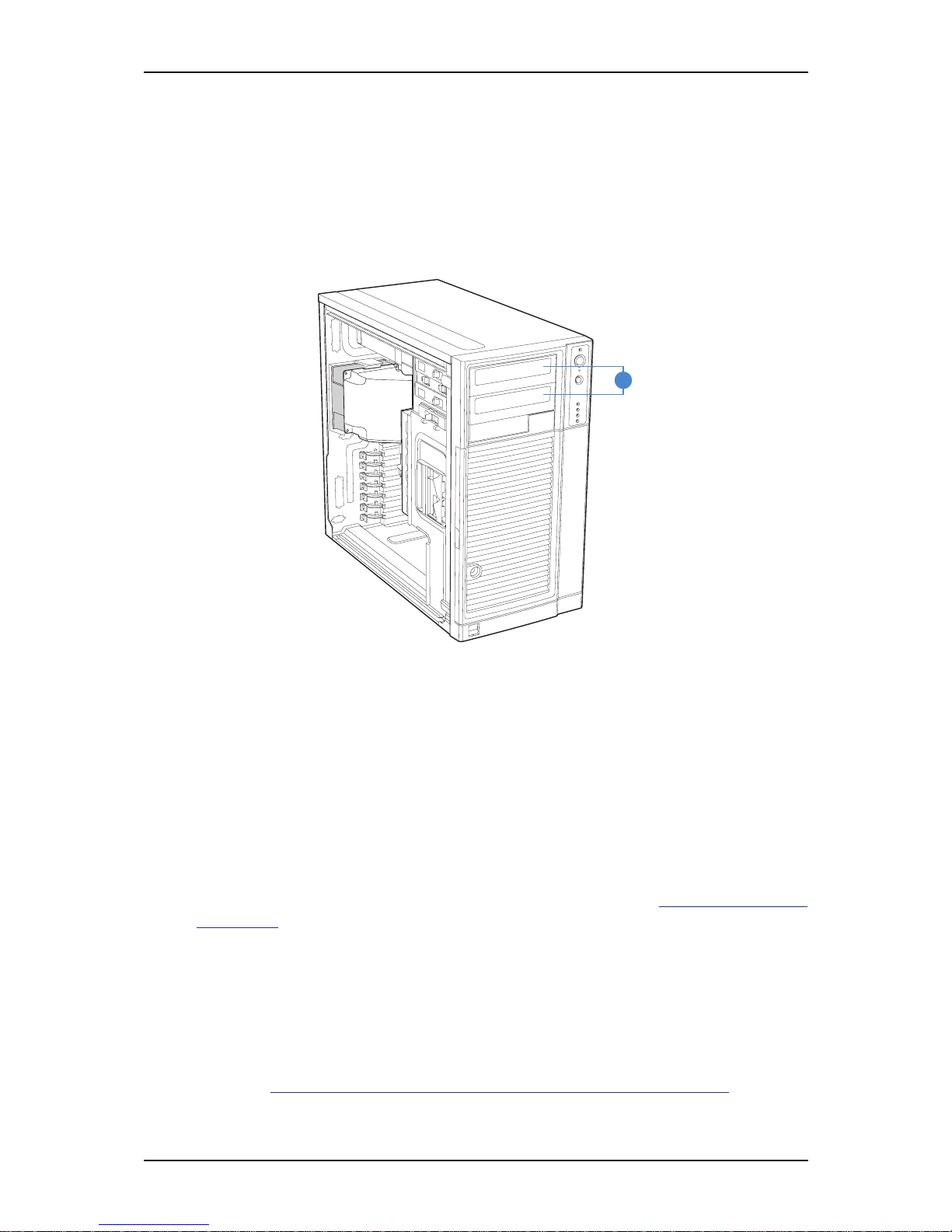
User Guide
47
www.bull.com
NovaScale T830 E1 Specific Features
Peripheral Bays
The system supports a variety of standard PC AT-compatible peripheral devices. The
chassis includes these peripheral bays:
■ T w o 5.25-inch file bays for installing half-height 5.25-inch peripheral devices such
as optional tape drives (An optical drive is factory-installed).
■ One 3.5-inch bay.
■ The hard disk drive cage in which S-ATA or SAS hard disk drives can be installed.
Expansion Slots
■ Two 32-bit/33MHz, 3V PCI connectors.
■ One x8 PCI Express connector (x4 lane).
■ One physical x8 PCI Express connector (x8 lane).
■ One physical x16 PCI Express connector (x8 lane).
These slots enable you to install additional LAN boards. Refer to “Optional Features”
on page 48 for details about the components that may be installed in the expansion
slots.
RAID Support
Although your motherboard features onboard RAID support, an additional controller
(factory-installed) is mandatory to take advantage of the hard disk drives hotswappability.
Refer to “
LSI 8708EM2 SAS/SATA RAID Controller” on page 58 for more
information.
A
Page 48

User Guide
48
www.bull.com
Optional Features
You will find hereafter information about the optional components that may be
installed in your system.
This is not an exhaustive list, some options may not be available any more, others may
have been added.
Page 49

User Guide
49
www.bull.com
DVD-ROM Drive
Features
■ DVD read speed: 16X max
■ SMART-X Smart Monitoring & Adjusting Read-speed Technology for eXtraction
■ ABS® (Auto Balance System) mechanism to reduce vibration & noise while high
speed rotating
■ Plug & Play with emergency manual eject
■ Belt Tray Loading Mechanism
Specifications
■ Speed (max):
- CD-ROM: 48x (7200 KB/s)
- DVD-ROM: 16x (21600 KB/s)
■ Buffer size: 1.8MB
■ Access time: 120 ms (CD family), 120 to 150 ms (DVD family)
■ Compatibility: ATAPI / E-IDE Half-Height internal DVD+R / DVD+R9 /
DVD+RW / DVD-R / DVD-RW / DVD-ROM / DVD-RAM / CD-R / CD-RW /
CD-ROM combination drive
Page 50

User Guide
50
www.bull.com
DVD Writer Combination Drive
Features
■ ATAPI / E-IDE Half-Height internal DVD+R / DVD+RW / DVD-R / DVD-RW /
DVD+R DL / DVD-R DL / DVD-ROM / CD-R / CD-RW / CD-ROM combination
drive.
■ Support Double Layer DVD +/- DL Recording Function.
■ SMART-BURN avoiding Buffer Under RunError, automatically adjusting writing
strategy and running OPC to provide the best burning quality.
■ SMART-X function adjusts CD-DA / VCD / DVD data extraction to a fastest
allowable speed according to both the data request rate from the host and the disk
quality.
■ ABS® system to reduce vibration and noise during recording and reading.
■ Supports Fixed Packet, Variable Packet, TAO, SAO, DAO, Raw Mode Burning &
Over-Burn.
■ DVD read compliant : DVD single/dual layer ( PTP / OTP ), DVD-R ( 3.9 GB / 4.7
GB ), DVD-R multi-borders, DVD+R, DVD+R multi-sessions, DVD-RW, and
DVD+RW.
■ CD read compliant : CD-DA, CD-ROM, CD-ROM / XA, Photo-CD, Multisession, Karaoke-CD, Video-CD, CD-I FMV, CD Extra, CD Plus, CD-R, and CDRW.
■ Supports both 8 cm and 12 cm CD and DVD discs.
■ Supports Fixed packet, Variable packet, Disc-at-once, Session-at-once and Track-
at-once.
■ Transfer modes: PIO mode 4, DMA mode 2 and Ultra DMA mode 4.
Specifications
■ Speed
- DVD+R: 16x max (write)
- DVD+R: 16x max (write)
- DVD-R: 16x max (write)
- DVD+R DL: 8x max (write)
- DVD+RW: 8x max (re-write)
- DVD-RW: 6x max (re-write)
- CD-R: 48x max (write)
- CD-RW: 32x max (re-write)
■ Buffer size: 2 MB
■ Access time: 160ms
■ Power requirements:
- +5v +/-5% and less than 100 mVp-p ripple voltage
- +12v +/-10% and less than 200 mVp-p ripple voltage
Page 51

User Guide
51
www.bull.com
DAT72 Tape Backup Unit (USB)
Please refer to the documentation on the Tape Online CD for more information.
Page 52

User Guide
52
www.bull.com
DLT-V4 Tape Backup Unit (SATA)
Note: The DLT-V4 is plugged on a PCI SATA controller
card. Do not plug it directly on the motherboard.
Please refer to the documentation on the Tape Online CD for more information.
Page 53

User Guide
53
www.bull.com
DAT160 Tape Backup Unit (USB)
Please refer to the documentation on the Tape Online CD for more information.
Page 54

User Guide
54
www.bull.com
GoVault Ba ckup Unit (SATA)
Please refer to the documentation on the Tape Online CD for more information.
Page 55

User Guide
55
www.bull.com
SAS Hard Disk Drive
■ Capacity: 73GB minimum
■ 15000 RPM
■ RAID support
Page 56

User Guide
56
www.bull.com
S-ATA Hard Disk Drive
■ SATA II specification.
■ Capacity: 80GB minimum
■ 7200 or 10k rpm
■ RAID support
Page 57

User Guide
57
www.bull.com
Adaptec SCSI Card 29320LPE
This card is a PCIe x1 Ultra320 SCSI controller that is ideal as a SCSI tape drive
connection solution thanks to its unparalleled PCIe connectivity, and the reliability and
stability of a single-channel I/O interface.
Note: refer to the Card User Guide for more information.
■ Interface: PCIe x1
■ Data transfer rate: up to 320Mbyte/sec.
■ Connectors:
- Internal: One 68-pin VHDCI
- External: One 68-pin Ultra320
■ Physical Specifications
- Size: 16,8cm x 6,5cm
Note: no internal SCSI tape drive is qualified for your
system.This card is used only to connect to external storage
devices.
Page 58
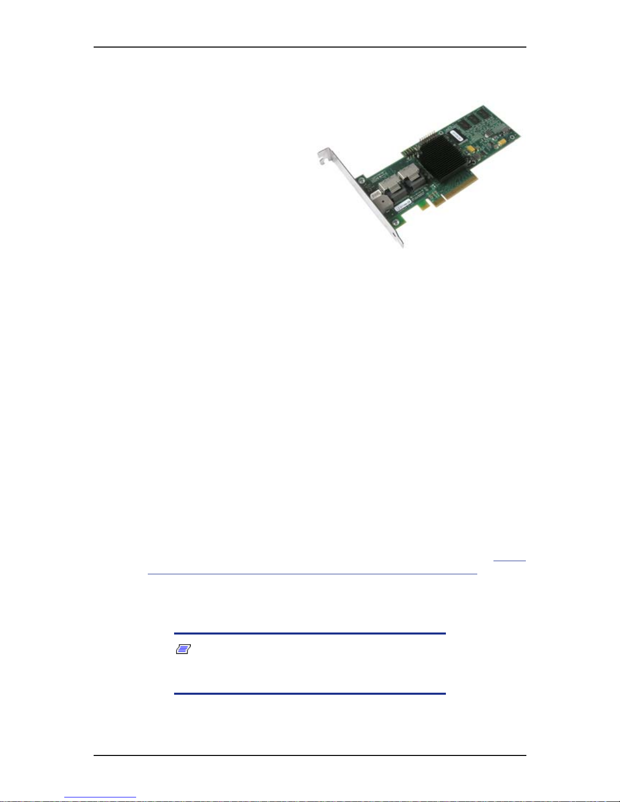
User Guide
58
www.bull.com
LSI 8708EM2 SAS/SATA RAID Controller
Features
■ 8 SAS/SATA compatible ports
■ Optional battery backup module
■ Optional RAID5/6 key activation
■ Connect up to 16 intermixed SAS
and SATA devices within the
same array
■ Auto-resume on array rebuild
■ Auto resume array reconstruction
■ Online Capacity Expansion
■ Comprehensive management tools
■ Audible alarm circuit
Specifications
■ Hardware Specifications:
- LSI SAS 1078 RAID Chip
- PCI Express compliant.
- 3 Gb/s per lane.
- x8 lane width.
- Cache memory of 128MB or 256MB DDRII 667MHz SDRAM (depending on
your configuration).
■ RAID Support:
- RAID Levels 0, 1, 10.
- RAID Levels 0, 1, 10, 5, and 6 with the optional activation key.
■ Configuration software: MegaRAID Management Suite. Refer to “RAID
Configuration using the MegaRAID Configuration Utility” on page 126.
- Online: MegaRAID Storage Manager Software.
- Pre-Boot: MegaRAID BIOS Configuration Utility (WebBIOS).
Notes:
For more information, refer to the documentation included on
the ExpressBuilder DVD-ROM.
Page 59

User Guide
59
www.bull.com
Setting Up Your System
This chapter describes how to select a site, unpack the system, make cable connections,
and power on the system units. Information on front and rear panel features, switches
and LEDs are also included in this chapter.
Page 60

User Guide
60
www.bull.com
Unpacking the System
When you receive your system, inspect the shipping containers prior to unpacking. If
the shipping boxes are damaged, note the damage, and if possible, photograph it for
reference.
Remove the contents of the containers, and keep the cartons and the packing materials.
If the contents appear damaged when you unpack the boxes, file a damage claim with
the carrier immediately.
The carton contains various accessories, as well as the system itself. If you find any
component missing or damaged, contact your service representative.
Store the provided accessories in a designated place for your convenience. You will
need them to install an optional device or troubleshoot your system, as well as to set it
up.
Make a backup copy of each provided discs, if any. Store the original disc as the master
disc in a designated place, and use its copy.
Improper use of any provided disc may alter your system environment. If you find
anything unclear, immediately ask your service representative for help.
Page 61
User Guide
61
www.bull.com
Setting Up Y our Server (Rack)
Setup Flow.
Selecting t
Select a suitable site for the server. Assemble the 19-inch rack assembly.
Unpack the server and accessories from the shipping carton box.
Install the server into the rack assembly.
Connect the peripheral devices to the server.
Connect the power cord to the server.
Power on the server to start software setups. Setups depend on the optional internal devices installed and
the peripheral devices connected.
If no operating system was factory-installed, install one to the server.
Install the utilities in the provided ExpressBuilder disc.
Making backup copie
After all the system setup procedures are completed, make backup copies of system information.
System information is required for recovering the server from trouble or after replacing the system board.
Page 62
User Guide
62
www.bull.com
Selecting Server Site
To use the server, install it in a standard EIA 19-inch rack assembly.
Refer to the documentation attached to the rack or contact your sales agent for more
information about setting up the rack.
Warning
Observe the following instructions to use the server safely. Failure to
follow these instructions may result in death or serious personal injury.
See “General Safety Information” on page 132 for details.
■ Do not use the server in any unapproved place.
■ Do not connect the ground line to a gas pipe.
Caution
Observe the following instructions to use the server safely. Failure to
follow these instructions may cause a fire, personal injury, or property
damage. See “General Safety Information” on page 132 for
details.
■ Do not carry or install the server on your own.
■ Do not concentrate the load in the rack.
■ Do not pull out a device from the rack if the rack is unstable.
■ Do not pull out more than one device at a time from the rack.
■ Do not exceed the rating power of the cables.
Do not install the rack in the places listed below. Installing the rack or mounting the
server in the rack installed in such places may cause some malfunctions to occur.
■ Narrow space from which the devices cannot be pulled out from the rack
completely.
■ Place that cannot bear the total weight of the rack and devices mounted on the rack.
■ Place where the stabilizers cannot be installed or where the rack can be installed
only after the practice of proper earthquake-resistant construction.
■ Place of uneven or slanting floor.
■ Place enduring drastic temperature changes (near a heater, air conditioner, or
refrigerator).
■ Place where intense vibrations may be generated.
■ Place where corrosive gazes are generated, chemicals are nearby, or chemicals
may be accidentally sprayed over.
Page 63

User Guide
63
www.bull.com
■ Place where a carpet that is not anti-static is laid.
■ Place where some objects may fall on the rack
■ Place near a device generating intense magnetic fields (such as a TV, radio,
broadcast/communication antenna, power transmission wire, and electromagnetic
crane) is placed. If it cannot be avoided, contact your sales agent to request proper
shielding measures.
■ Place where the power cord of the server must be connected to an AC outlet that
shares the outlet of another device with large power consumption.
■ Place near equipment that generates power noise (e.g., contact spark at power-on/
power-off of commercial power supply through a relay). If you must install the
server close to such equipment, request separate power cabling or noise filter
installation from your sales agent.
Page 64
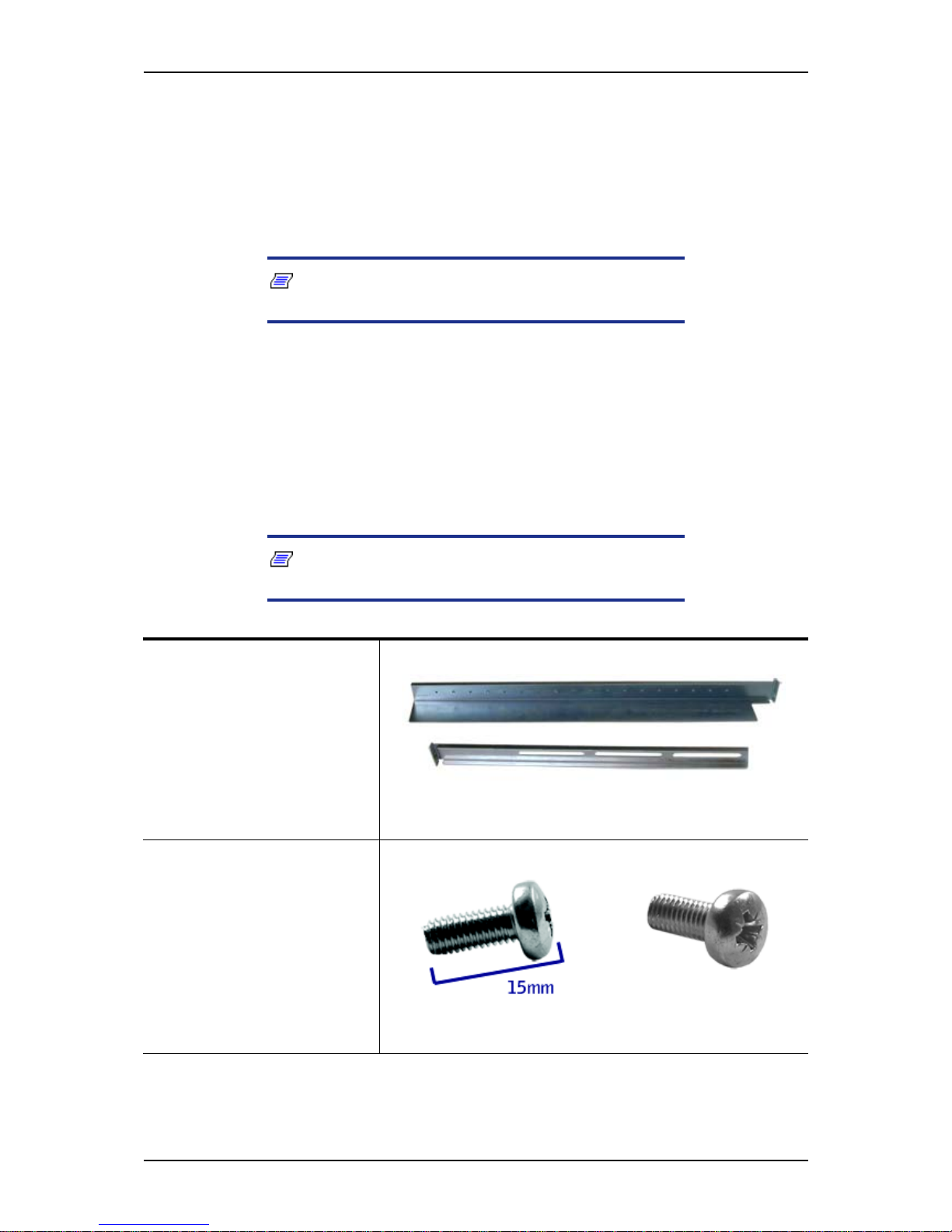
User Guide
64
www.bull.com
NovaScale T810 E1 Rack Installation Kit
Assembly
This section provides the assembly instructions for mounting the server into a standard
19-inch rack cabinet.
Note: The server shown in the pictures may be slightly
different from your server system.
Unpacking the Rack Installation Kit
Although the rack installation kit is inspected and carefully packaged at the factory,
damage may occur during shipping. Follow these steps for unpacking.
1. Visually inspect the shipping containers; notify your carrier immediately of
any damage.
2. Carefully remove the rack mounting hardware and verify the parts.
Note: The quantities noted below are subject to change
without notice.
2 sets of support rail assemblies (1 front and 1 rear part for
each)
Figure 20: Rail assembly front and rear parts
(right side shown)
6 (minimum) self-tapping
screws (TCB M5) for support
rails front and rear parts
assembling
Figure 21: Self-tapping screws
Page 65
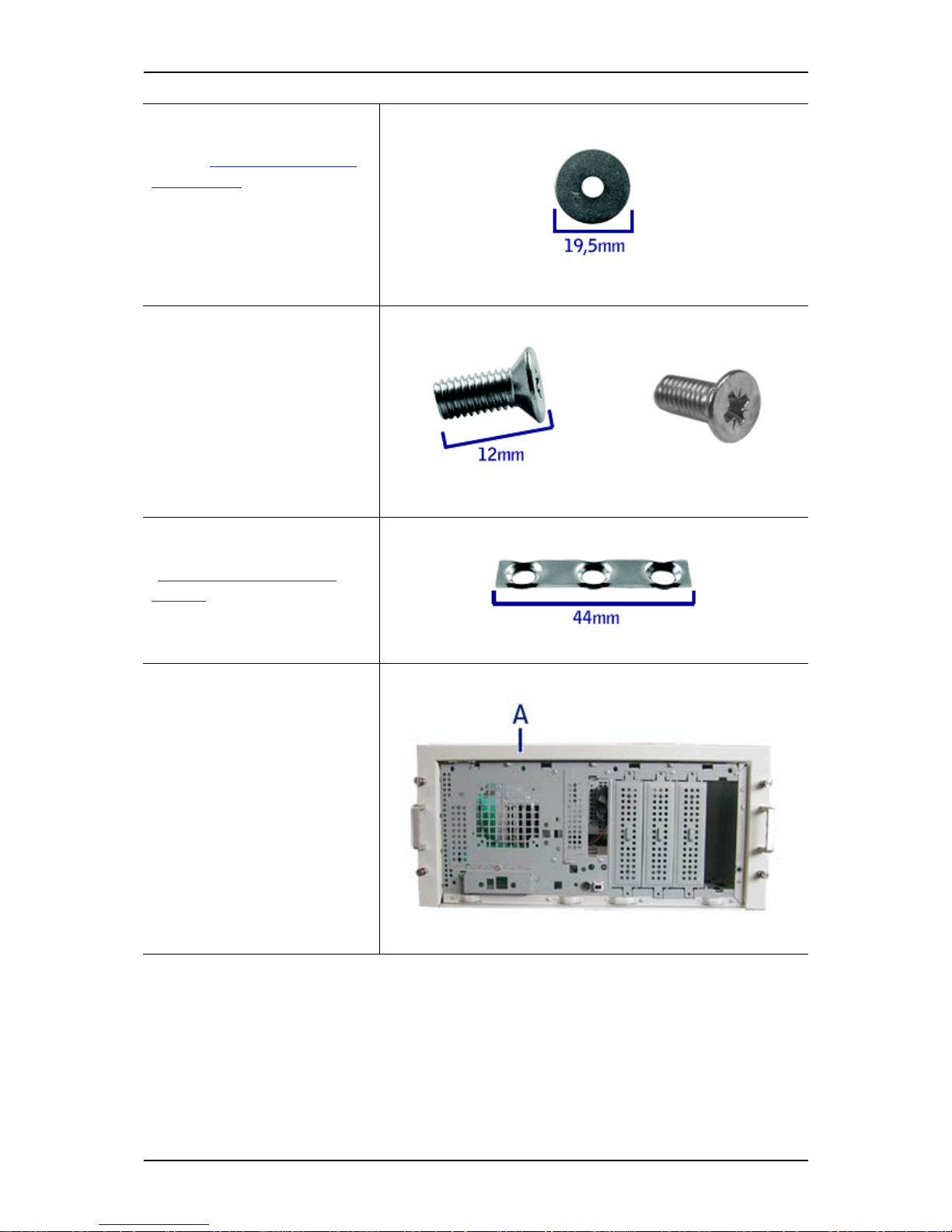
User Guide
65
www.bull.com
6 (minimum) washers, to be
used with the 6 self-tapping
screws ("Figure 21: Self-tap-
ping screws")
Figure 22: Washers for the self-tapping screws
8 (minimum) flange head
screws (M5x12) used to fix
the support rail assemblies to
the rack
Figure 23: Flange head screws
4 washer plates, to be used
with the flange head screws
("Figure 23: Flange head
screws")
Figure 24: Washer plates
Rack mounting frame
Figure 25: Rack-mounting frame (A)
Page 66
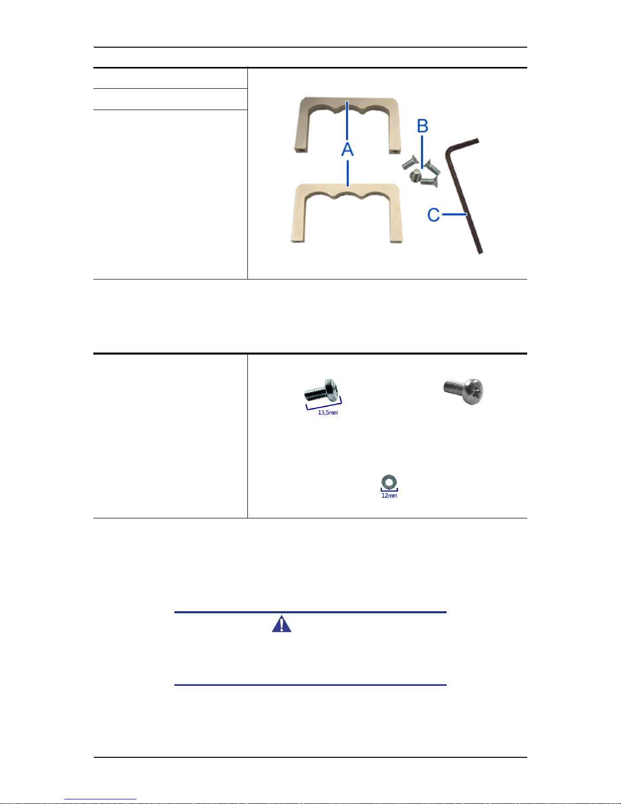
User Guide
66
www.bull.com
If some of the parts listed above are missing or if the hardware is damaged, notify your
server representative.
Additional Parts for Future Use
Before You Begin
Before you begin, please review the following cautions, warnings, and general
guidelines.
Warning
Be sure that power to the system is turned off and unplugged.
All voltage is removed only when the power cords are
unplugged.
■ Avoid excessive vibration and shock. Dropping an electronic component can cause
serious damage.
2 Handles (A)
Figure 26: Handles (A), screws (B) and hex key (C)
4 Handles fixing screws (B)
1 Hex key for frame grub-
screws (C)
8 (minimum) screws (TCB
M5)
Figure 27: Screws
8 (minimum) washers
Figure 28: Washers
Page 67

User Guide
67
www.bull.com
■ Do not disconnect or remove parts other than those specified in the procedure.
■ Do not touch I/O connector pins.
■ All screws are Phillips-head, unless otherwise specified.
■ On completion of any assembly or reassembly, perform a power-on test. If a fault
occurs, verify that the assembly or reassembly was performed correctly. If the
problem persists, see “Solving Problems” on page 264.
Static Precautions
An electrostatic discharge (ESD) can damage disk drives, option boards, and other
components. You can provide some ESD protection by wearing an anti-static wrist
strap attached to chassis ground when handling system components.
Electronic devices can be easily damaged by static electricity. To prevent damage, keep
them in their protective packaging when they are not installed in your system.
Assembly
The following subsection describes how to assemble your rack-mount server into a
standard 19-inch rack cabinet.
Before you begin select an appropriate location in your rack cabinet for the rack-mount
server. To improve rack stability, mount heavier items towards the bottom of the rack
cabinet. If the rack is a stand-alone unit and the rack is more than 75% filled with
components, consider installing an optional stabilizer kit.
Note: When planning your system configuration for the rack
cabinet you should consider the length of the cables that interconnect system components.
Warning
■ ANCHOR THE EQUIPMENT RACK: The equipment rack must be
anchored to an unmovable support to prevent it from falling
over when one or more servers are extended in front of it on
slide assemblies. The anchors must be able to withstand a
force of up to 113 kg (250 lbs). You must also consider the
weight of any other device installed in the rack.
■ MAIN AC POWER DISCONNECT: You are responsible for install-
ing an AC power disconnect for the entire rack unit. This
main disconnect must be readily accessible, and it must be
labelled as controlling power to the entire unit, not just to the
server(s).
■ GROUNDING THE RACK INSTALLATION: To avoid the potential
for an electrical shock hazard, you must include a third wire
safety grounding conductor with the rack installation. If a
Page 68
User Guide
68
www.bull.com
server power cord is plugged into an AC outlet that is part of
the rack, then you must provide proper grounding for the
rack itself. If server power cords are plugged into wall AC
outlets, the safety grounding conductor in each power cord
provides proper grounding only for the server. You must
provide additional, proper grounding for the rack and other
devices installed in it.
Caution
Temperature: The operating temperature of the server, when
installed in an equipment rack, must not go below 5 °C or rise
above 35 °C. Extreme fluctuations in temperature can cause a
variety of problems in your server.
Ventilation: The equipment rack must provide sufficient airflow
to the front of the server to maintain proper cooling. It must also
include ventilation sufficient to exhaust a maximum of 4,100
Btu's per hour for the server. The rack selected and the
ventilation provided must be suitable to the environment in
which the server will be used.
Note: For vertical reference, every three screw holes on the
rack vertical mounting rail are equal to 1U (1.75 inc hes ) .
Mounting holes in the vertical rails of equipment racks are commonly spaced in a 5/8 x 5/8 x 1/2-inc h sequence. Perform the
following steps carefully; brackets must be moun ted with precision to allow room for the next server you install in a rack.
Assembling the Front and Rear Parts of Support Rails
The support rails are made of a front and a rear part. Those two parts may be adjusted
to fit the distance between the front and rear vertical rails of the rack.
1. Assemble the front (A) and rear (B) parts of the right support rail with 3 self
tapping screws (C) and 3 flat washers (D).
Note: When using self-tapping screws, we recom mend you
tighten the screw for 3 quarters of a turn, and loosen for 1
quarter. Repeat this cycle until the screw is completely
tightened.
Page 69
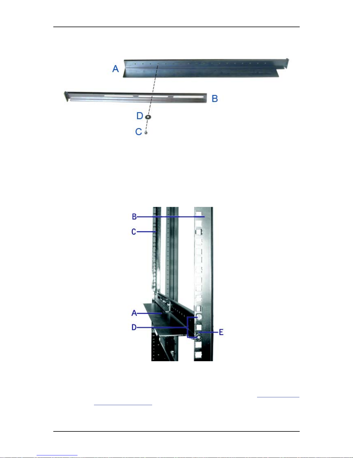
User Guide
69
www.bull.com
2. Adjust the total length to fit the distance between the front and rear vertical
rails of the rack before securing the screws.
Figure 29: Right support rail front and rear parts, fixing screws and washers
3. Assemble the left support rail the same way.
Installing the Support Rails
1. Install the right support rail (A) as shown in illustration.
2. Secure the rail to the front (B) and rear (C) vertical mounting rails with two
flange head screws (D) and the washer plate (E).
Figure 30: Installing the right support rail
3. Depending on your configuration, insert one or several caged nuts in the holes
that will allow you to secure the system on the vertical rails.
Insert the caged nuts in the front mounting rail as follows (see "Figure 31:
Inserting a caged nut"):
Page 70
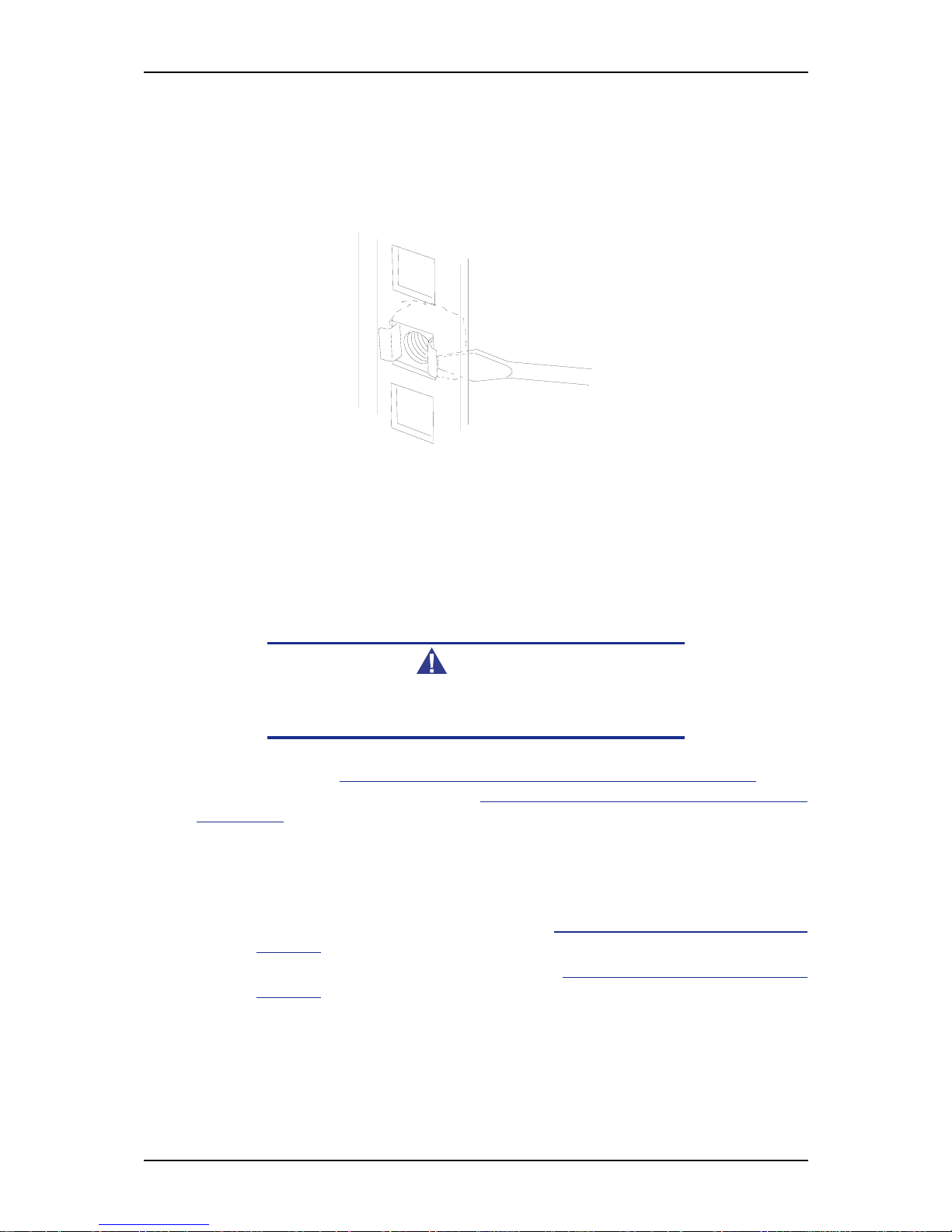
User Guide
70
www.bull.com
a. Position the caged nut on the inside of the front vertical mounting rails.
b. Hook the side lip of a caged nut into the square hole in the rail.
c. Push the other side lip of the caged nut into the square hole in the rail
until it is secured.
d. Repeat for each caged nut.
Figure 31: Inserting a caged nut
4. Repeat steps 1 to 3 for the left support rail.
Attaching the Handles to the Rack Mounting Frame
Two handles are attached to the rack mounting frame. The handles are used to easily
slide the server in and out of the rack.
Warning
The handles are only used to slide the server in an d out of the
rack. DO NOT use these handles to carry the server.
Attach the handles (A in "Figure 26: Handles (A), screws (B) and hex key (C)") to the
rack mounting frame with two screws (B in "Figure 26:
Handles (A), screws (B) and
hex key (C)").
Installing the Rack Mounting Frame on the Server
Install the rack mounting frame on the server as follows:
1. Remove the right side door as described in “Removing the Right Side Door” on
page 139.
2. Remove the front panel as described in “Removing the Front Panel” on
page 141.
Page 71
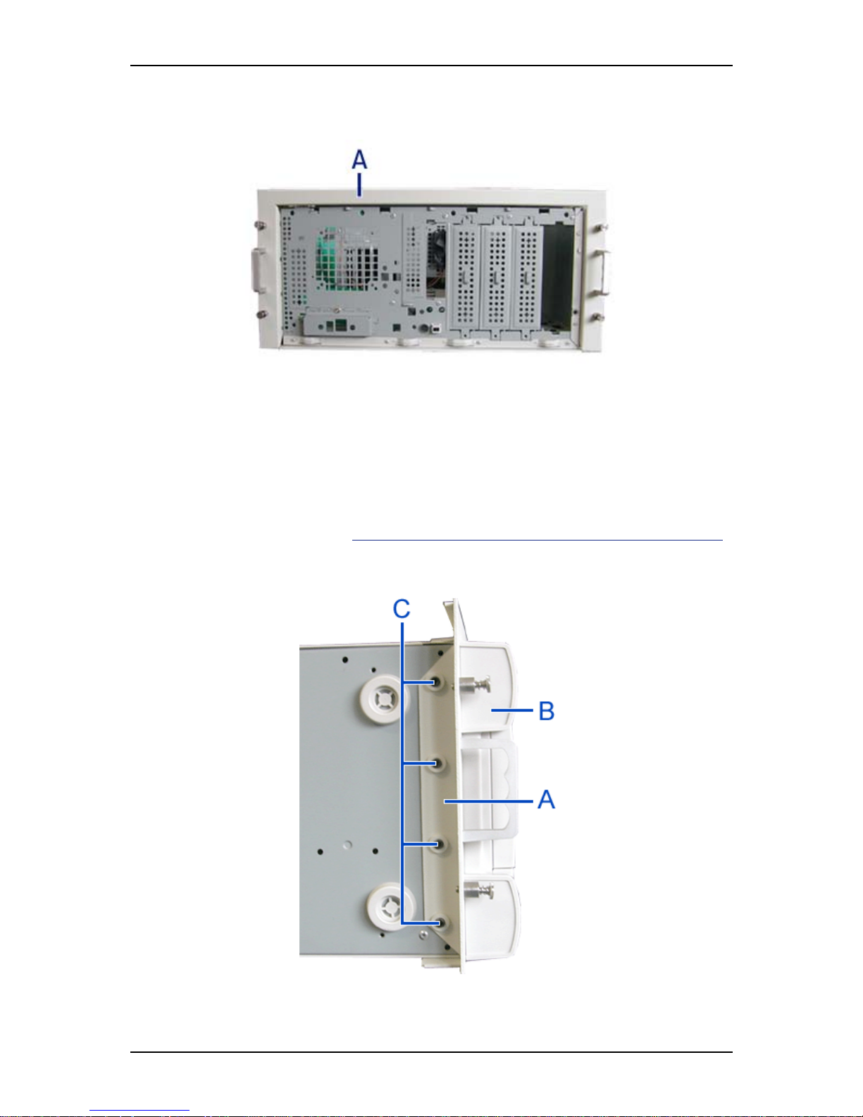
User Guide
71
www.bull.com
3. Install the rack mounting frame (A) on the server (B) as shown in the figure
below.
Figure 32: Installing the rack mounting frame on the server
4. Slide the rack mounting frame on the server until the front of the server
protrude a little from the frame.
5. Replace the front panel.
6. Replace the right side door.
7. Align the rack mounting frame (A in the figure above) with the front panel (B).
8. Secure the frame with the grubscrews (C in the figure below, four on each side)
using the hex key (C in "Figure 26: Handles (A), scr ews (B) and hex key (C)").
Tighten the screws to fix the frame to the server, but do not overtighten in
order to prevent damage to the server case.
Figure 33: Securing the rack mounting frame
Page 72
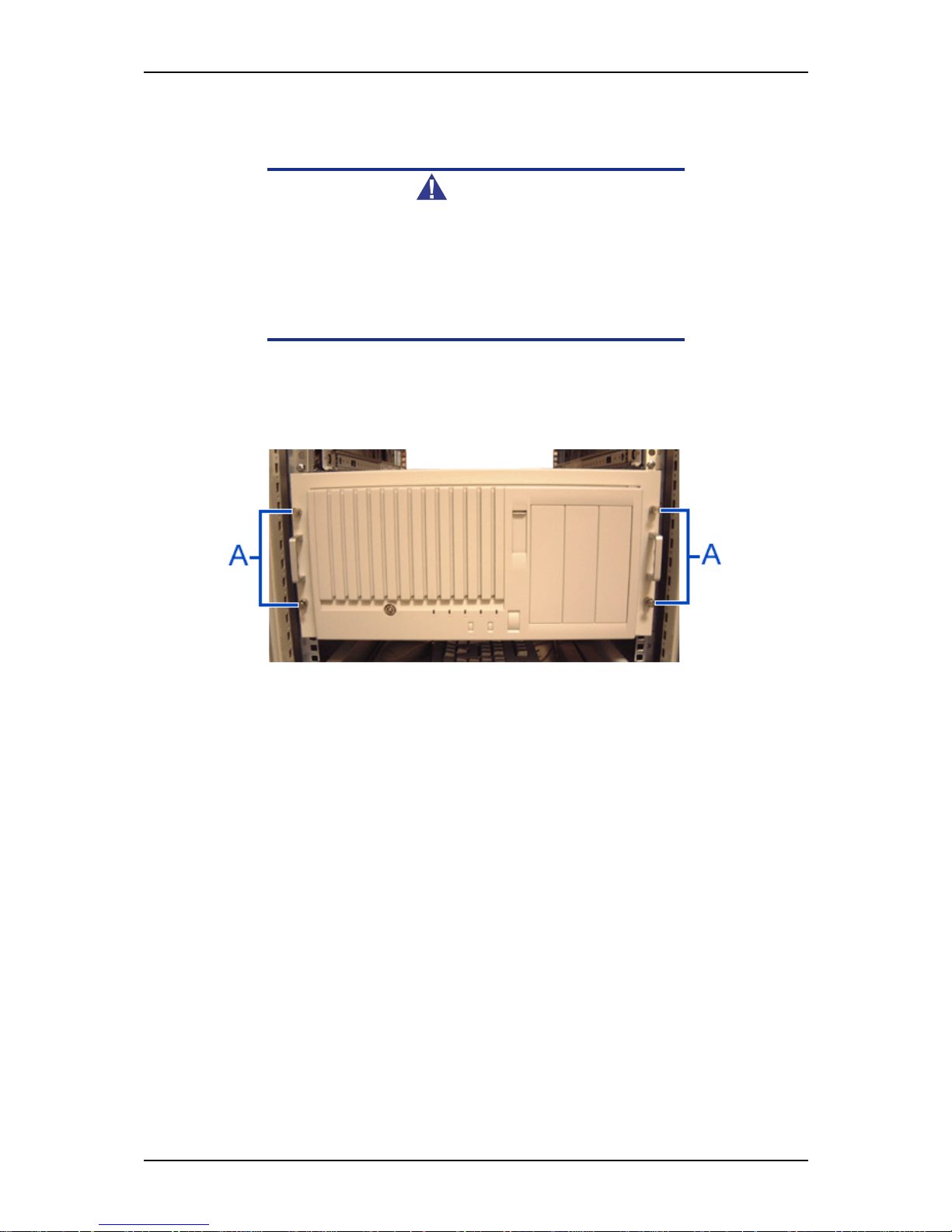
User Guide
72
www.bull.com
Installing the Server in the Rack Cabinet
Warning
The system can weigh up to 23.5 kg. If it contains numerous
optional boards and peripheral devices, it will weigh more. To
avoid personal injury, make sure you have at least one person
help you lift or move the system.
Do not use the handles of the rack mounting frame to lift the
server.
1. Lift the server onto the support rails and slide it toward the rear of the cabinet.
2.
Secure the server to the vertical mounting rails with the four thumbscrews (A in the
figure below).
Figure 34: Securing the server to the rack cabinet
Page 73

User Guide
73
www.bull.com
NovaScale R410 E1 Rack Installation Kit
Assembly
This section provides the assembly instructions for mounting the server into a standard
19-inch rack cabinet.
Two rack-mount kits are available for your server:
- Rack-mount kit with short rails (standard).
- Rack-mount kit with long rails (optional). A cable arm can be installed when
these sliding rails are fitted.
Read the general information on installing a system into a rack, and then jump to the
installation instructions for the kit you have at your disposal.
Before You Begin
Before you begin, please review the following cautions, warnings, and general
guidelines.
Warning
Be sure that power to the system is turned off and unplugged.
All voltage is removed only when the power cords are
unplugged.
■ Avoid excessive vibration and shock. Dropping an electronic component can cause
serious damage.
■ Do not disconnect or remove parts other than those specified in the procedure.
■ Do not touch I/O connector pins.
■ All screws are Phillips-head, unless otherwise specified.
■ On completion of any assembly or reassembly, perform a power-on test. If a fault
occurs, verify that the assembly or reassembly was performed correctly. If the
problem persists, see “Solving Problems” on page 264.
Static Precautions
An electrostatic discharge (ESD) can damage disk drives, option boards, and other
components. You can provide some ESD protection by wearing an anti-static wrist
strap attached to chassis ground when handling system components.
Electronic devices can be easily damaged by static electricity. To prevent damage, keep
them in their protective packaging when they are not installed in your system.
Page 74
User Guide
74
www.bull.com
Inserting a System into a Rack
Before you begin, select an appropriate location in your rack cabinet for the rackmount server. To improve rack stability, mount heavier items towards the bottom of the
rack cabinet.
Note: When planning your system configuration for the rack
cabinet you should consider the length of the cables that
interconnect system components.
Warning
■ ANCHOR THE EQUIPMENT RACK: The equipment rack must be
anchored to an unmovable support to prevent it from falling
over when one or more servers are extended in front of it on
slide assemblies. You must also consider the weight of any
other device installed in the rack.
■ MAIN AC POWER DISCONNECT: You are responsible for install-
ing an AC power disconnect for the entire rack unit. This
main disconnect must be readily accessible, and it must be
labelled as controlling power to the entire unit, not just to the
server(s).
■ GROUNDING THE RACK INSTALLATION: To avoid the potential
for an electrical shock hazard, you must include a third wire
safety grounding conductor with the rack installation. If a
server power cord is plugged into an AC outlet that is part of
the rack, then you must provide proper grounding for the
rack itself. If server power cords are plugged into wall AC
outlets, the safety grounding conductor in each power cord
provides proper grounding only for the server. You must
provide additional, proper grounding for the rack and other
devices installed in it.
Page 75
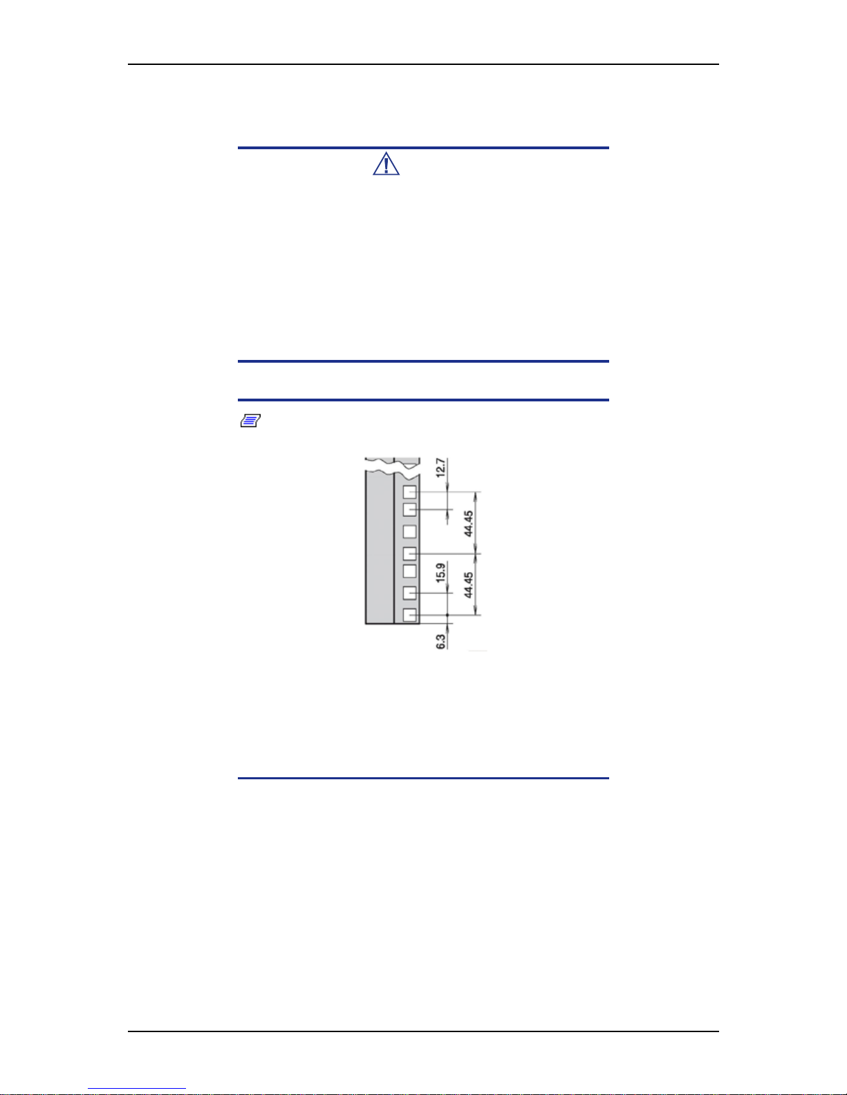
User Guide
75
www.bull.com
Caution
Temperature: The operating temperature of the server, when
installed in an equipment rack, must not go below 5 °C or rise
above 35 °C. Extreme fluctuations in temperature can cause a
variety of problems in your server.
Ventilation: The equipment rack must provide sufficient airflow
to the front of the server to maintain proper cooling. It must also
include ventilation sufficient to exhaust the total sum of the Btu's
per hour for the servers installed in the rack. The rack selected
and the ventilation provided must be suitable to the
environment in which the server will be used.
Note: For vertical reference, every three screw holes on the
vertical mounting rail are equal to 1U (1.75 inches) .
Figure 35: 1U specifications (in millimeters)
Mounting holes in the vertical mounting rails of equipment racks
are commonly spaced in a 5/8 x 5/8 x 1/2-inch sequence. Perform the following steps carefully; brackets must be mounted
with precision to allow room for the next server you install in a
rack.
Page 76
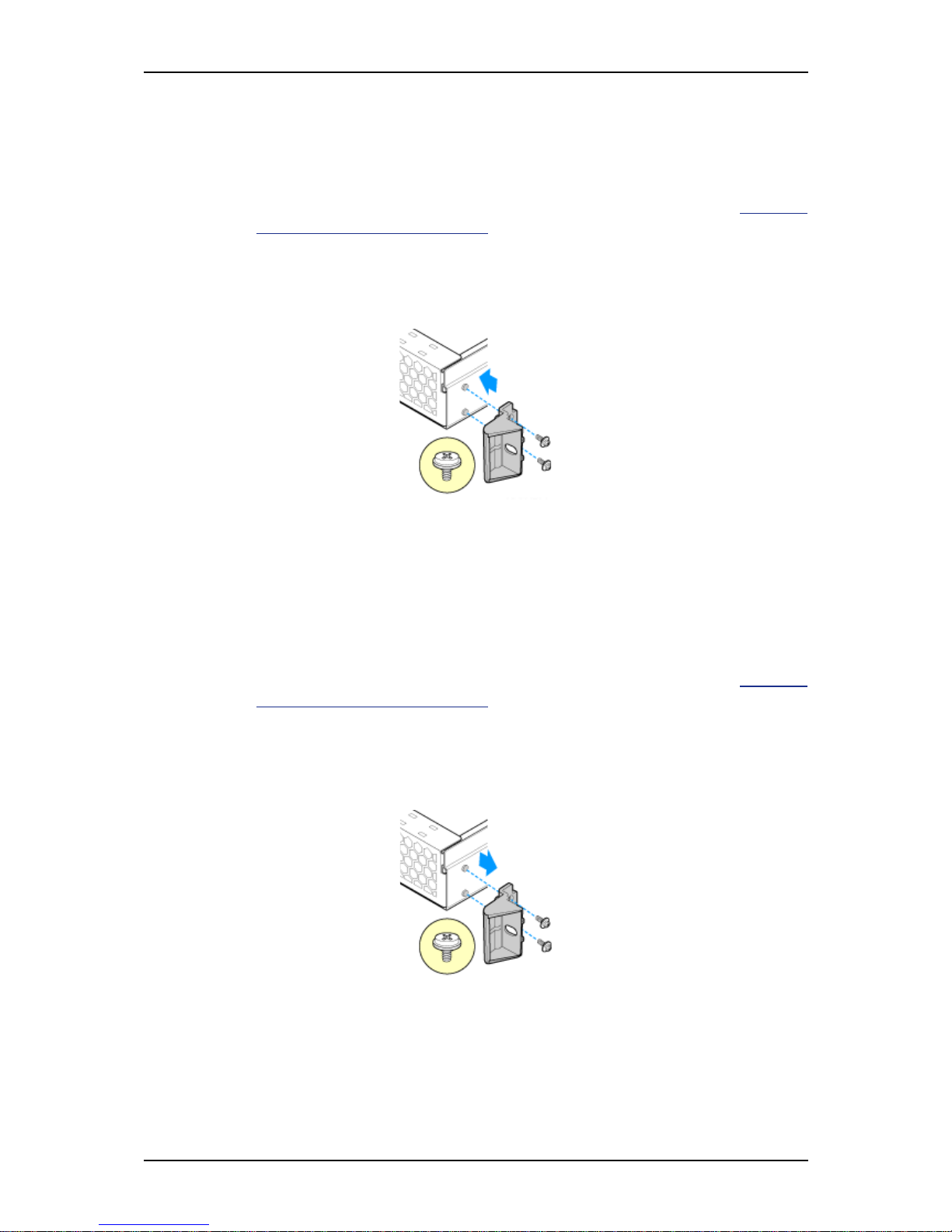
User Guide
76
www.bull.com
Installing and Removing the Rack Handles
Installing the Rack Handles
1. Make sure the power switches for the computer, video monitor and any
peripheral devices are turned OFF and unplug the power cord (see “General
Safety Information” on page 132).
2. If applicable, disconnect the monitor and peripheral devices (printers, for
instance) from the system.
3. Attach the rack handle to the server system with two screws as shown in the
figure below.
Figure 36: Installing the Rack Handle
4. Repeat step 3 on the opposite side of the server.
5. Plug all peripheral devices and the AC power cable into the server.
Removing the Rack Handles
1. Make sure the power switches for the computer, video monitor and any
peripheral devices are turned OFF and unplug the power cord (see “General
Safety Information” on page 132).
2. If applicable, disconnect the monitor and peripheral devices (printers, for
instance) from the system.
3. Remove the two screws holding the rack handle in place, and remove the rack
handle from the server system as shown in the figure below.
Figure 37: Removing the Rack Handle
4. Repeat step 3 on the opposite side of the server.
5. Plug all peripheral devices and the AC power cable into the server.
Page 77
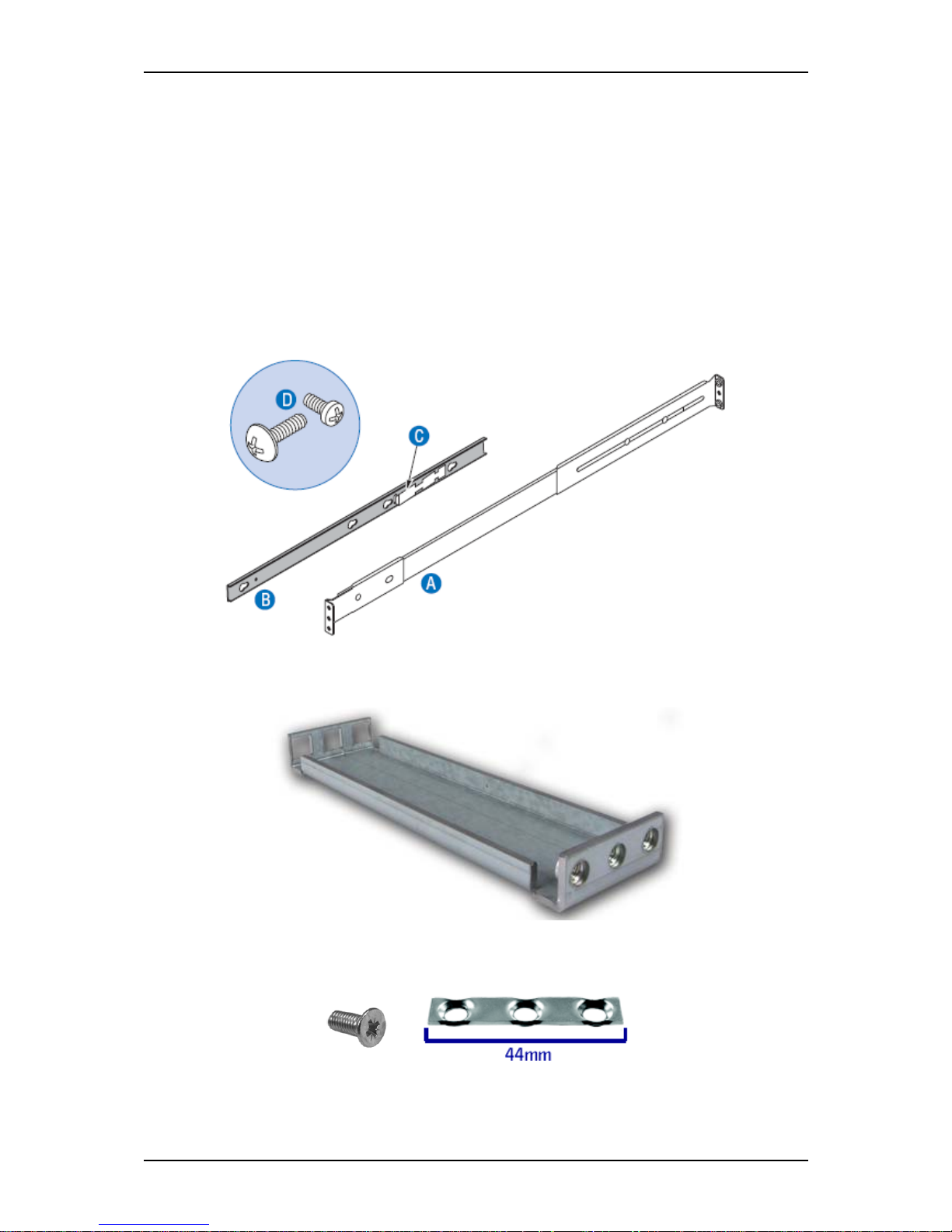
User Guide
77
www.bull.com
Installing a Rack Mount Kit with the Basic Rails
Kit Contents
Each rack mount kit contains the following:
- Outer rail slide assembly (2) - letter “A” on the picture below.
- Inner rail slide (2) - letter “B” on the picture below.
- Rail safety stop (one each on inner slides) - letter “C” on the picture below.
- Outer slide rail screws (8 #10-32 x 1/2), inner slide rail screws (8 #6-32 x 1/4),
and rack screws (2 #10-32 x 3/4) - letter “D” on the picture below.
Figure 38: Rack Mount Kit Contents
- Rail extensions (2), to be used if the rack depth is superior to 765 mm.
Figure 39: Rails Extensions
- Washerplates (4), to be used with M5 screws (8).
Page 78
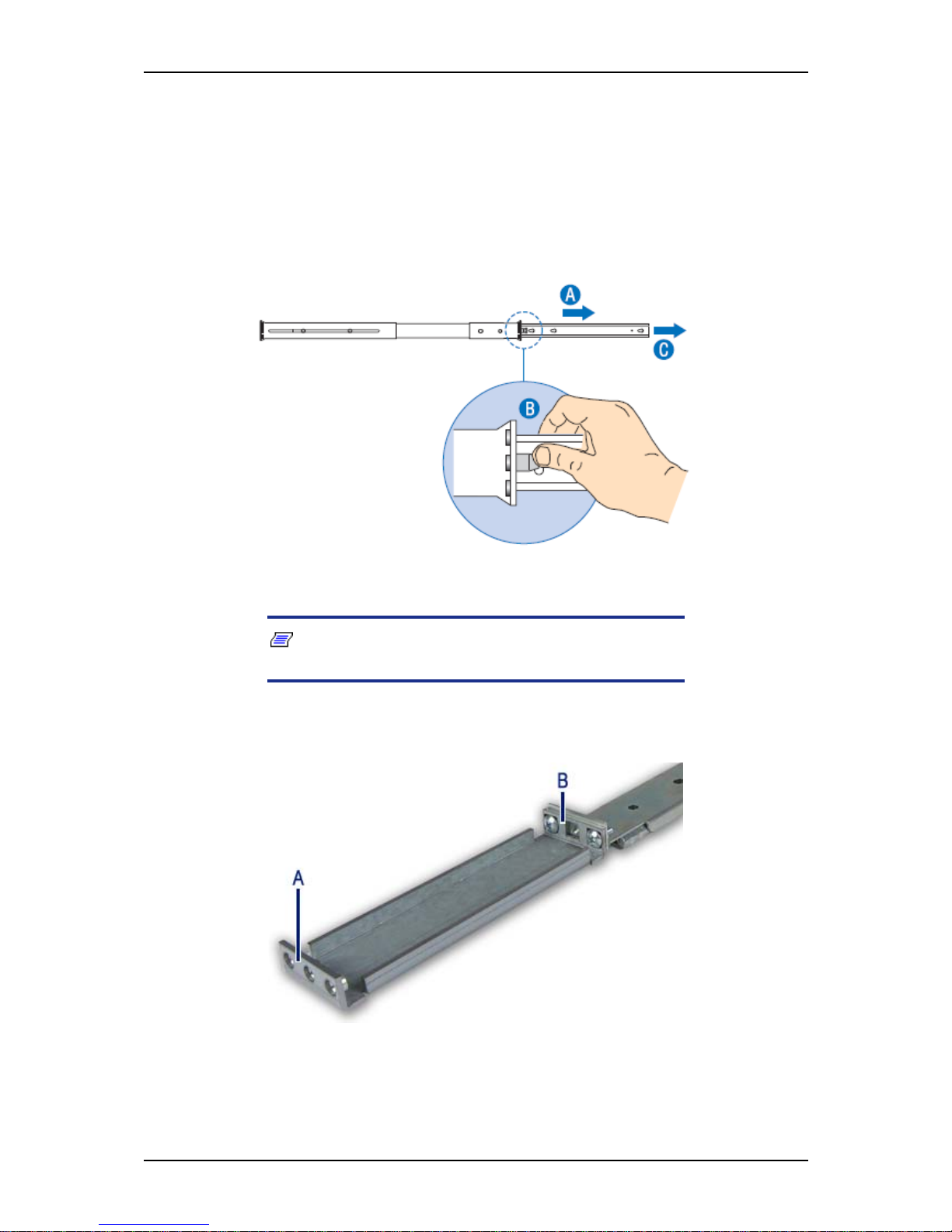
User Guide
78
www.bull.com
Assembly
1. Power down the server and unplug all peripheral devices and the AC power
cable.
2. Remove the inner rail from the rail assembly.
a. Extend the inner rail until it locks (letter “A”).
b. Depress the spring safety lock to release the inner rail (letter “B”).
c. Remove the inner rail from the rail assembly (letter “C”).
Figure 40: Removing the Inner Rail from the Rail Assembly
3. Optional: fix an extension to the rear of each slide rail.
Note: Use extensions only if the rack depth is superior to
765 mm.
Attach the bracket with square holes (see letter “B”) to the rear of the outer rail
using two 10-32 x 1/2 screws.
Figure 41: Attaching the Extension to the Rail
A: Bracket with square holes
B: Bracket with round holes
Page 79
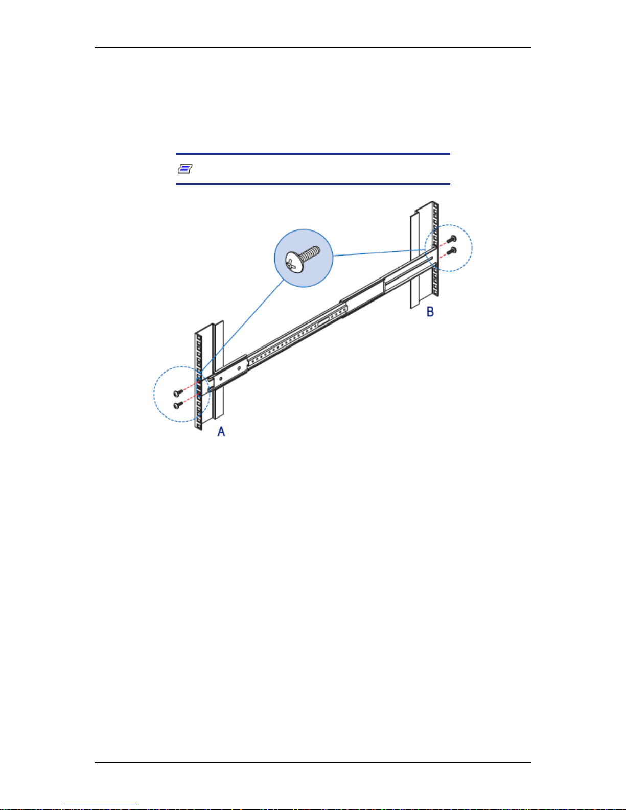
User Guide
79
www.bull.com
4. Determine the position in which you wish to install the system into the rack.
5. Attach the outer rail slides to the vertical mounting rails using:
- two #10-32 x 1/2 screws at the front mounting rails,
- two M5 screws and one washerplate (it only fits one way) at the rear
mounting rails.
Note: The rail flanges mount to the inside of each post.
Figure 42: Installing the Outer Rail to the Mounting Rails
A: Front of the rack
B: Rear of the rack
Page 80
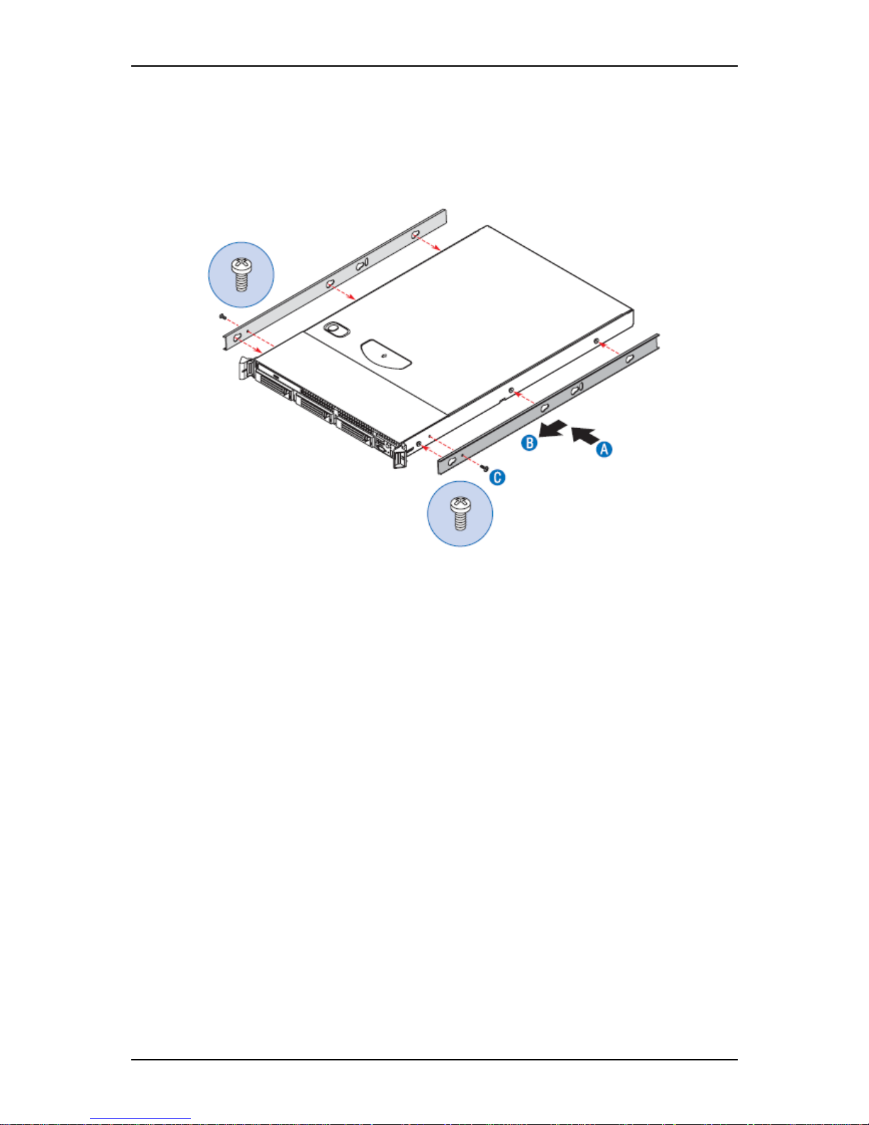
User Guide
80
www.bull.com
6. Attach the inner rails to the server chassis sidewalls
a. Insert the inner rails over the server chassis sidewall studs (letter “A”).
b. Slide the inner rails toward the front of the server chassis (letter “B”).
c. Secure the inner rails with one #6-32 x 1/4 screw for each rail (letter
“C”).
Figure 43: Attaching the Inner Rails to the Chassis
Page 81
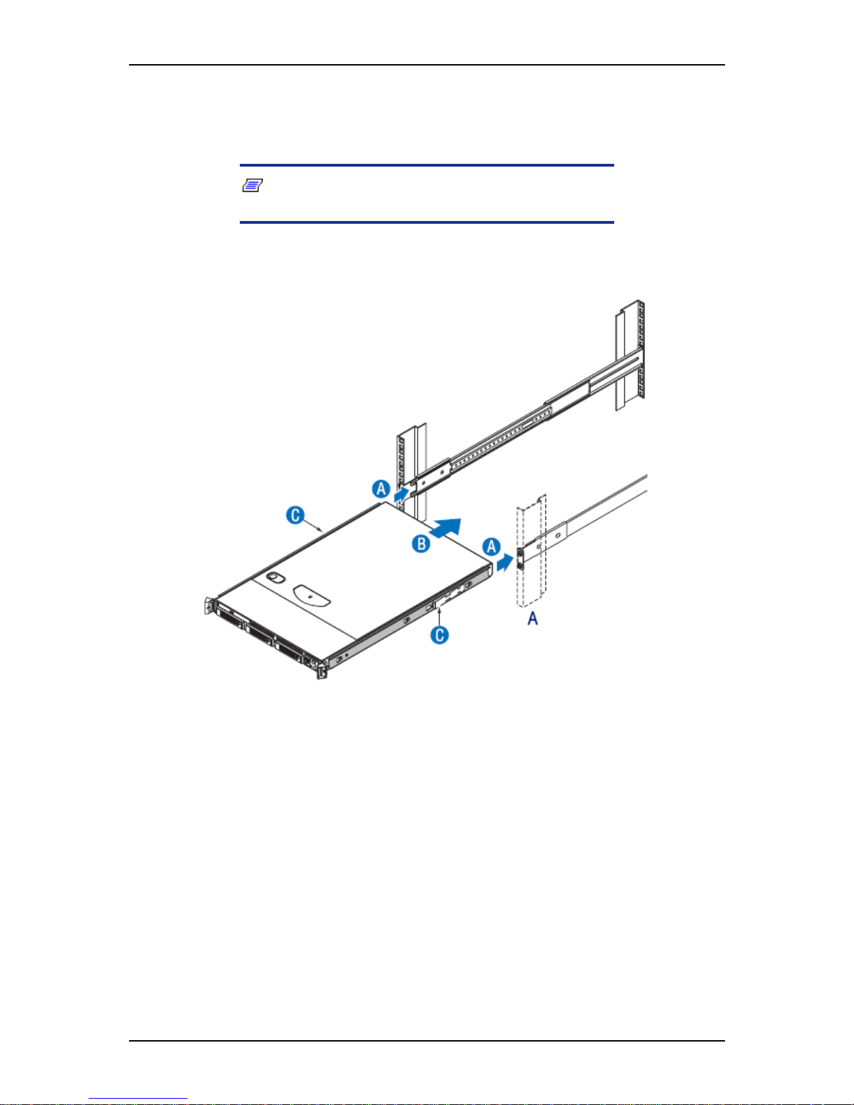
User Guide
81
www.bull.com
7. Install the server chassis into the rack.
a. Align the inner rails (attached to the server chassis) with the outer rail
assemblies (attached to the rack). See letter “A”.
Note: The inner slides must be positioned all the way
forward in the rails to ensure proper installation of the server.
b. Engage the matching rails and slide the server chassis into the rack
(letter “B”) until the two safety stops lock into position (letter “C”).
Figure 44: Installing the Server Chassis into the Rack (step 1)
A: Front of the rack
Page 82
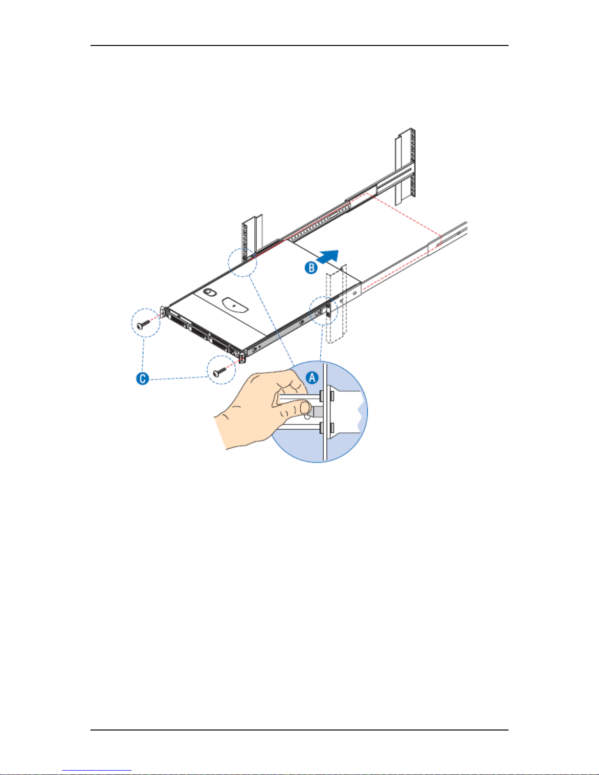
User Guide
82
www.bull.com
c. Depress the two safety locks -one on each side- (letter “A”).
d. Slide the server chassis all the way into the rack (letter “B”).
e. Use the rack screws (#10-32 x 3/4) to secure the chassis and rack
handles into the rack (letter “C”).
Figure 45: Installing the Server Chassis into the Rack (step 2)
Page 83
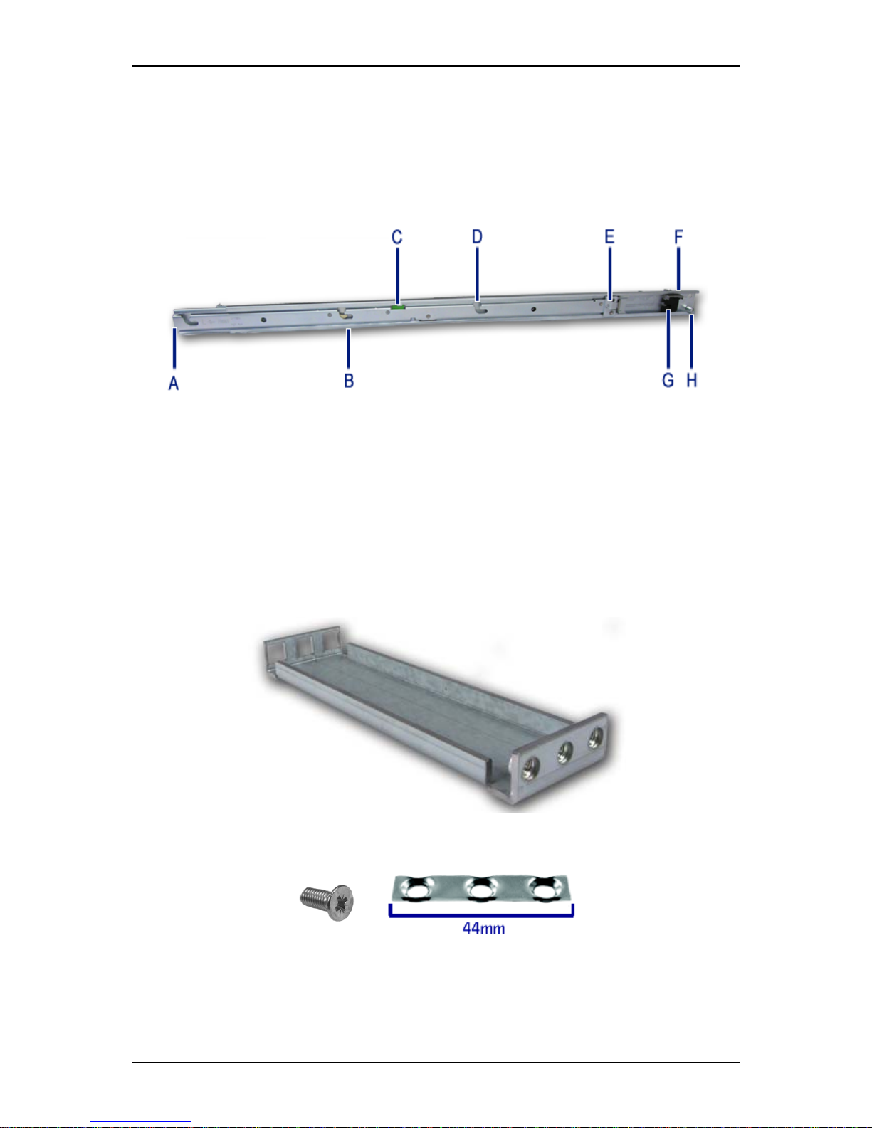
User Guide
83
www.bull.com
Installing a Rack Mount Kit with Sliding Rails (option)
Kit Contents
Each rack mount kit contains the following:
- Slide rail assemblies (2)
Figure 46: Slide Rail Description
A: Front multi-pin adapter and bracket
B: Component release lever
C: Slide extension release lever
D: Component mounting channel (3 per rail)
E: Front (sliding) cable arm mount
F: Rear multi-pin adapter and bracket
G: Anti-sag bar slider
H: Rear (fixed) cable arm mount
- Rail extensions (2), to be used if the rack depth is superior to 760 mm.
Figure 47: Rail Extensions
- Washerplates (4), to be used with M5 screws (8).
- Cabling straps (6)
Page 84
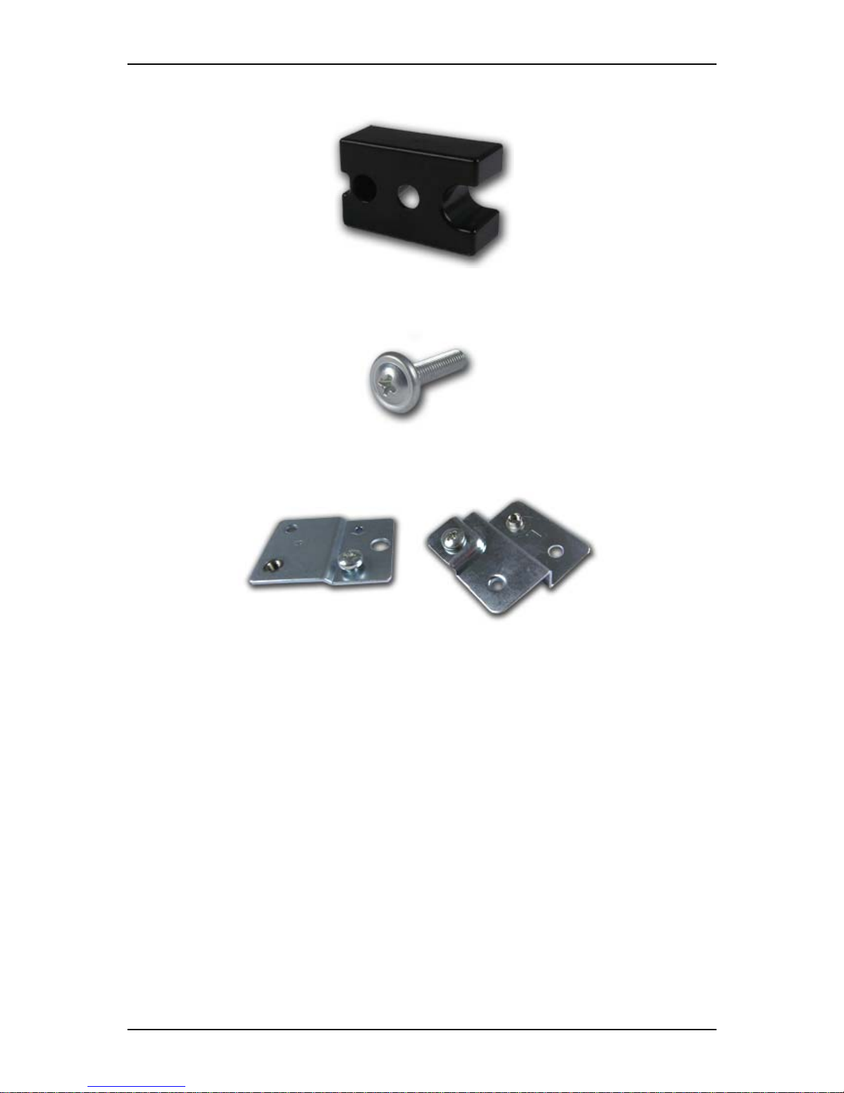
User Guide
84
www.bull.com
- Spacer block (1)
Figure 48: Spacer Block
- Screws (not used)
Figure 49: Screws
- Extensions 2 x 2 (not used)
Figure 50: Extensions
Page 85
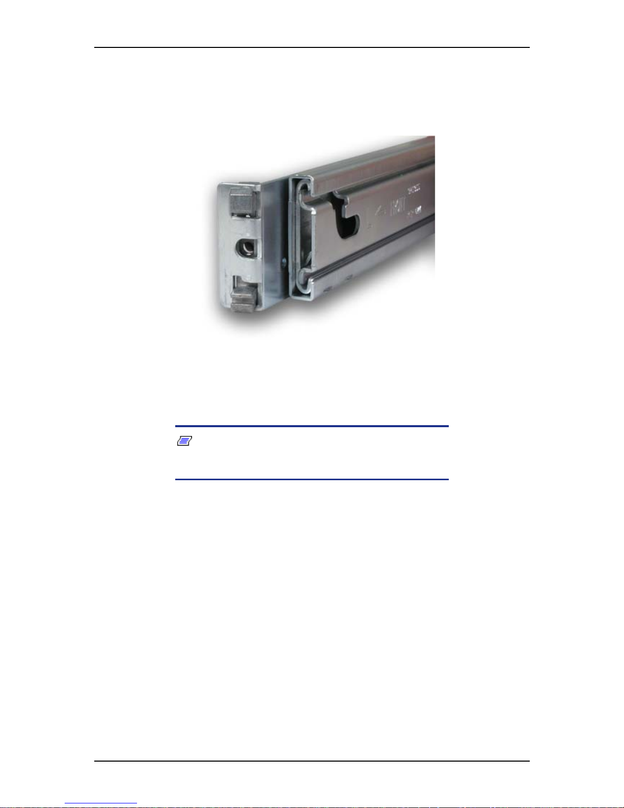
User Guide
85
www.bull.com
Assembly
1. Power down the server and unplug all peripheral devices and the AC power
cable.
2. Set the multi-pin adapter for the rack-type.
Figure 51: Front Multi-Pin Adapter and Bracket
(set with square pins)
The multi-pin adapters allow the slide rails to be used in racks that have square
or round mounting holes.
Note: The sliding rails are shipped with the multi-pin
adapters set for square holes. If you are equipped with an NEC
rack or another rack with square mounting holes, skip this step.
Reverse the multi-pin adapter position to match the rack mounting hole type (if
necessary) as described in the following steps:
Page 86
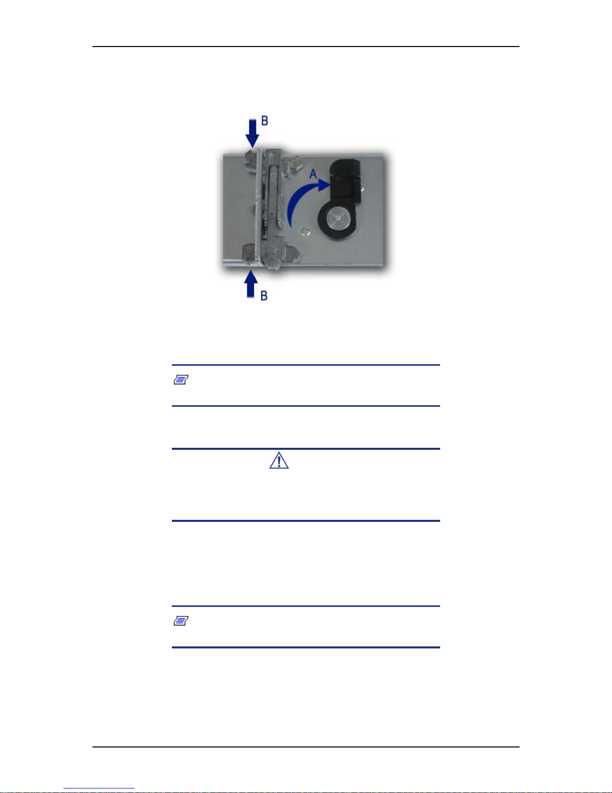
User Guide
86
www.bull.com
a. Rotate the swivel lock to the “up” position (letter “A”).
b. Press the mounting pins together, and then pull completely out the
multi-pin adapter from the multi-pin bracket (letter “B”).
Figure 52: Changing the Adapter Pins Set
c. Install the multi-pin adapter with the round pins facing out. Press the
pins together while inserting the adapter into the bracket.
Note: the multi-pin adapter is keyed to prevent incorrect
insertion. Turn it around if it does not squarely fit.
Caution
The multi-pin adapter must be fully locked in the bracket. Make
certain both mounting pins on the multi-pin adapters are fully
engaged in the multi-pin bracket.
d. Lock the multi-pin adapter in place using the swivel lock.
e. Repeat steps a through d for both ends of each slide rail.
3. Optional: fix an extension to the rear of each slide rail.
Note: Use extensions only if the rack depth is superior to
760 mm.
Page 87
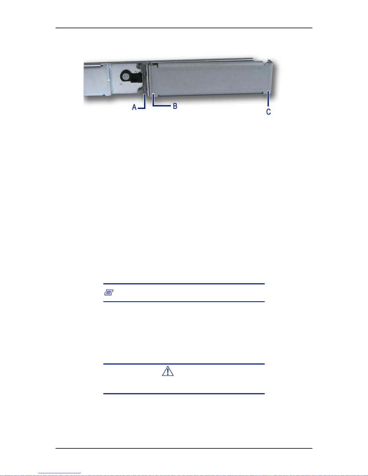
User Guide
87
www.bull.com
Figure 53: Attaching the Extension to the Rail
A: Multi-pin adapter
B: Bracket with square holes
C: Bracket with round holes
a. Press together the round pins of the multi-pin adapter and insert the
bracket with the square holes on the round pins.
b. Release the round pins of the multi-adapter.
4. Determine the position in which you wish to install the system into the rack.
5. Align the left slide rail with its mounting holes.
6. Hold the slide rail in the desired rack-mounting position.
7. Depending on whether you are using, or not, the extensions:
■ With the extensions: use a washerplate and 2 M5 screws (it only fits one
way) to secure the rear bracket of the rail to the mounting rail.
■ Without the extensions: press the multi-pin adapter mounting pins (see
Figure 51) together and secure the rear bracket of the rail to the mounting
rail.
Note: Ensure the slide rail is level.
8. Fully extend the slide rail to its fully extended (locked) position.
9. Press the slide extension release levers to release the lock.
10. Move the slide rail in and out throughout its entire range of motion and make
certain it does not bind.
Caution
If you notice any binding, recheck the mounting positions.
Page 88
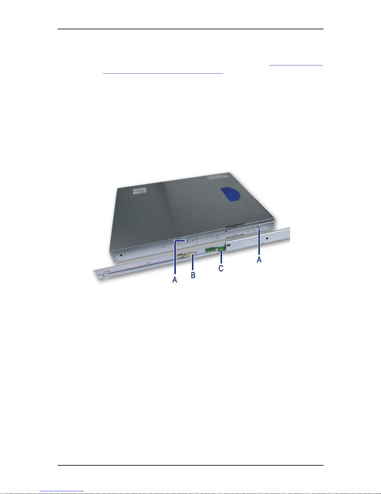
User Guide
88
www.bull.com
11. Repeat steps 5 through 10 for the right slide rail, ensuring that it is parallel and
level with the left slide rail.
12. If you wish to install a cable arm, follow the instructions in “Installing a Cable
Arm (with Sliding Rails Only)” on page 89 before going to step 13
13. Extend both slide rails into the fully extended (locked) position.
14. Align the mounting studs with the component mounting channels on the slide
rails.
15. Carefully place the component mounting studs in the component mounting
channels on the slide rails.
Allow the component mounting studs to fully seat in the component mounting
channels (letter “D” on Figure 46). The component release levers (one on each
slide rails) pivot out of the way and then back in place whent the studs are fully
engaged in the mounting channels.
Ensure that the component release levers are in locked position.
Figure 54: Placing the System on the Rails
A: Mounting studs
B: Slide extension release lever
C: Component release lever
16. Use two rack screws (#10-32 x 3/4) to secure the chassis and rack handles into
the rack.
17. Press and hold the left and right slide extension release levers and slowly slide
the component and side rails into the fully retracted position.
Page 89
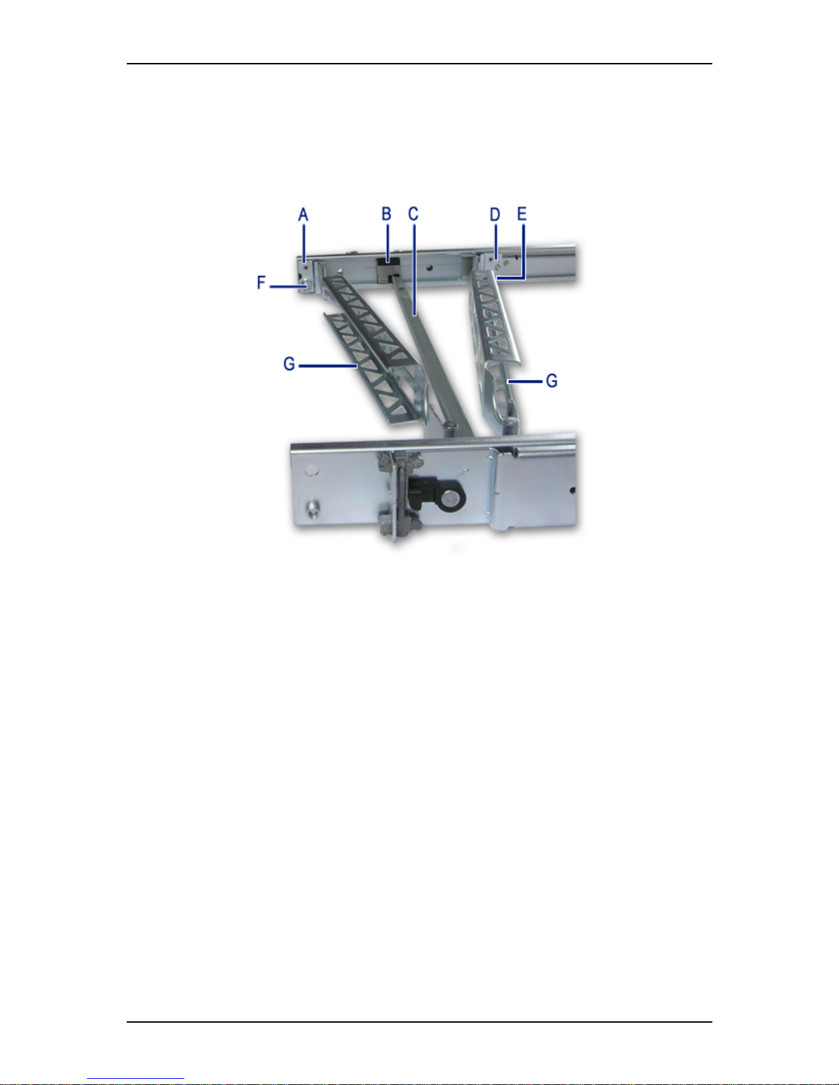
User Guide
89
www.bull.com
Installing a Cable Arm (with Sliding Rails Only)
Description
The cable arm pivots at its rear mounting position, and slides along its front mounting
position with the sliding rail track.
Figure 55: Cable Arm Description
A: Rear (pivoting) end
B: Anti-sag bar slider
C: Anti-sag bar
D: Front (sliding) end
E & F: Captive thumbscrew
G: Cabling channel
Page 90
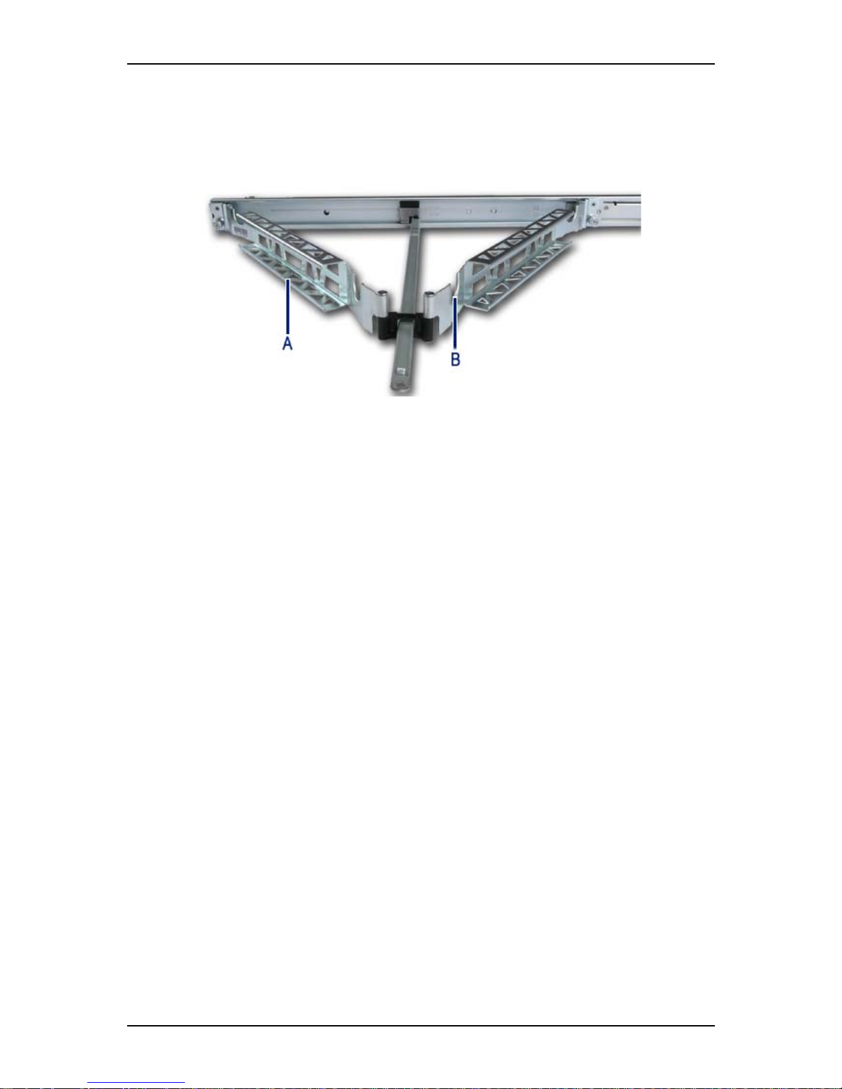
User Guide
90
www.bull.com
Installation Requirements
The cable arm can be installed either on the left sliding rail, or on the right sliding rail
(the mounting tabs on either end are identical). Regardless of the selected position, the
cable arm must be oriented as shown below to properly function.
Figure 56: Installing the Cable Arm on the Sliding Rails
A: The open side of the channels are facing out.
B: The cabling cut-outs are facing up.
Page 91
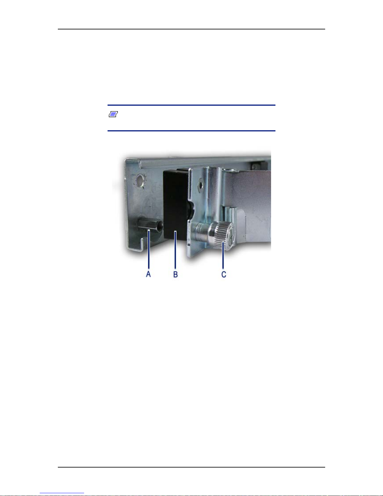
User Guide
91
www.bull.com
Installation
1. Pull the slide rails out to the fully extended (locked) position.
2. Loosely position the cable arm in the mounting position, noting the placement
requirements specified above.
3. Install the spacer block (letter “B”) in mounting position at the end of the cable
arm chosen to be the rear (pivoting) end.
Note: The black spacer block is provided in the plastic bag
with the cabling straps.
Figure 57: Installing the Spacer Block
A: Jackscrew
B: Spacer block
C: Captive thumbscrew
Page 92
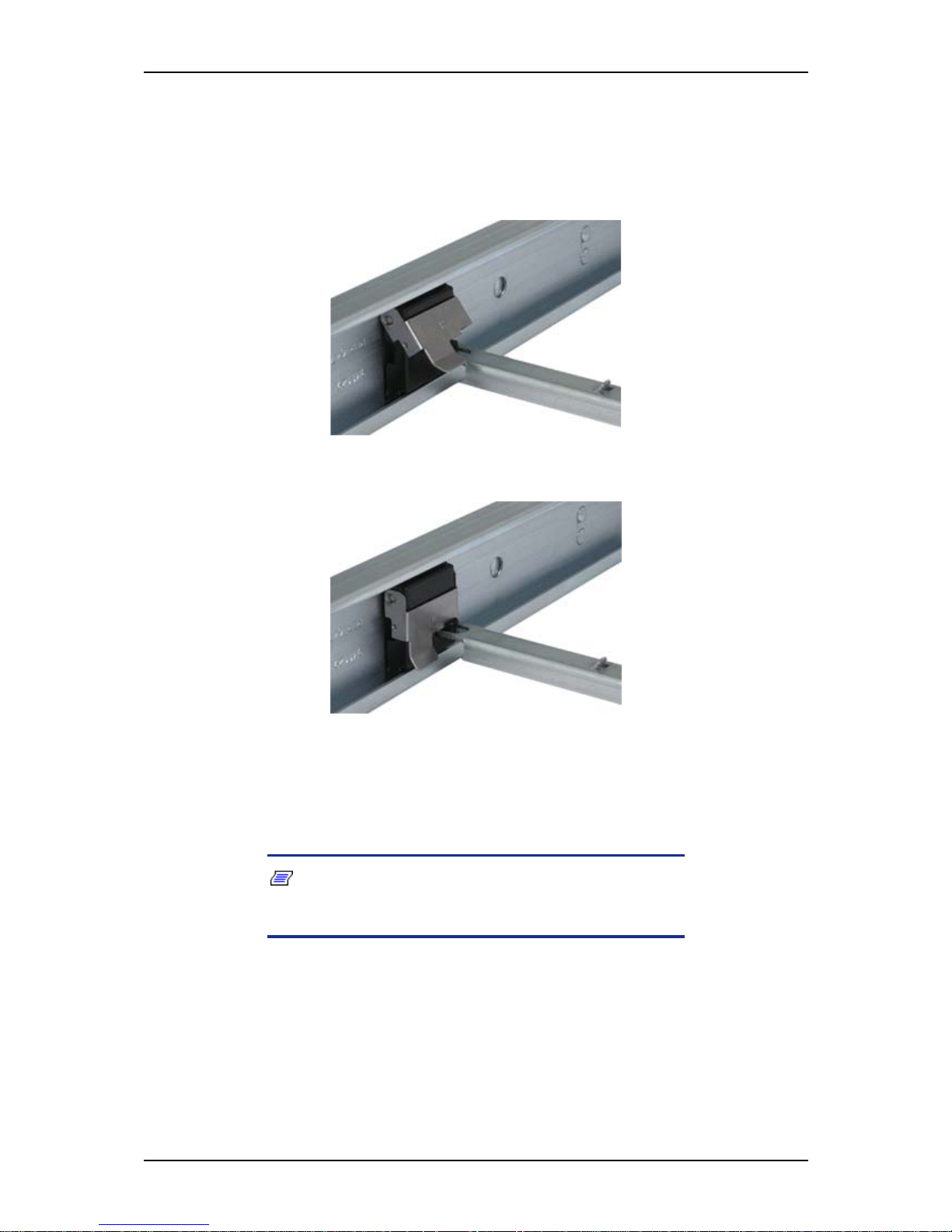
User Guide
92
www.bull.com
4. Attach the cable arm (along with the spacer block) to the rear of the sliding rail
using the captive thumbscrews (letter “A” on Figure 57).
5. Open the locking clips on the anti-sag bar slider on both slide rails by lifting
the silver tab.
6. Attach the anti-sag bar to the anti-sag bar sliders on the left and right slide rails.
Figure 58: Attaching the Anti-Sag Bar
7. Place the ends of the anti-sag bar over the pins.
Figure 59: Closing the Anti-Sag Bar Slider
8. Attach the front sliding end of the cable arm to the slide rail track using the
captive thumbscrew.
9. Press and hold the left and right slide extension release levers and slowly move
the slide rails throughout their entire range of motion.
Note: Ensure the cable arm folds and expands without
binding. If binding is noticed, recheck the mounting of the cable
arm.
Page 93

User Guide
93
www.bull.com
10. Place and secure the cabling within the cable arm.
a. Install the sytem in the slide rails, as described in steps 13 to 16 of
“Installing a Rack Mount Kit with Sliding Rails (option)” on page 83,
and fully extend the slide rails until they lock.
b. Connect all the required cables to the component.
c. Place the cables in the cable cutouts and into the cabling channels.
d. Use the supplied straps to secure the cables within the cabling channels.
Notes:
■ Wrap the straps through the back of the cabling channels.
■ Never wrap the straps around the bottom of the cable arm.
Ensure that excess strap length is either cut off, or secured
to the other straps and placed in the cabling channel with the
cables.
e. Press and hold the left and right slide extension release levers and
slowly slide the component throughout its entire range of motion to
ensure that cabling is not strained or restricting movement of the sliding
rails.
Note: Make certain cabling is not pinched when the rails
and cable arm are in the fully retracted position.
Page 94
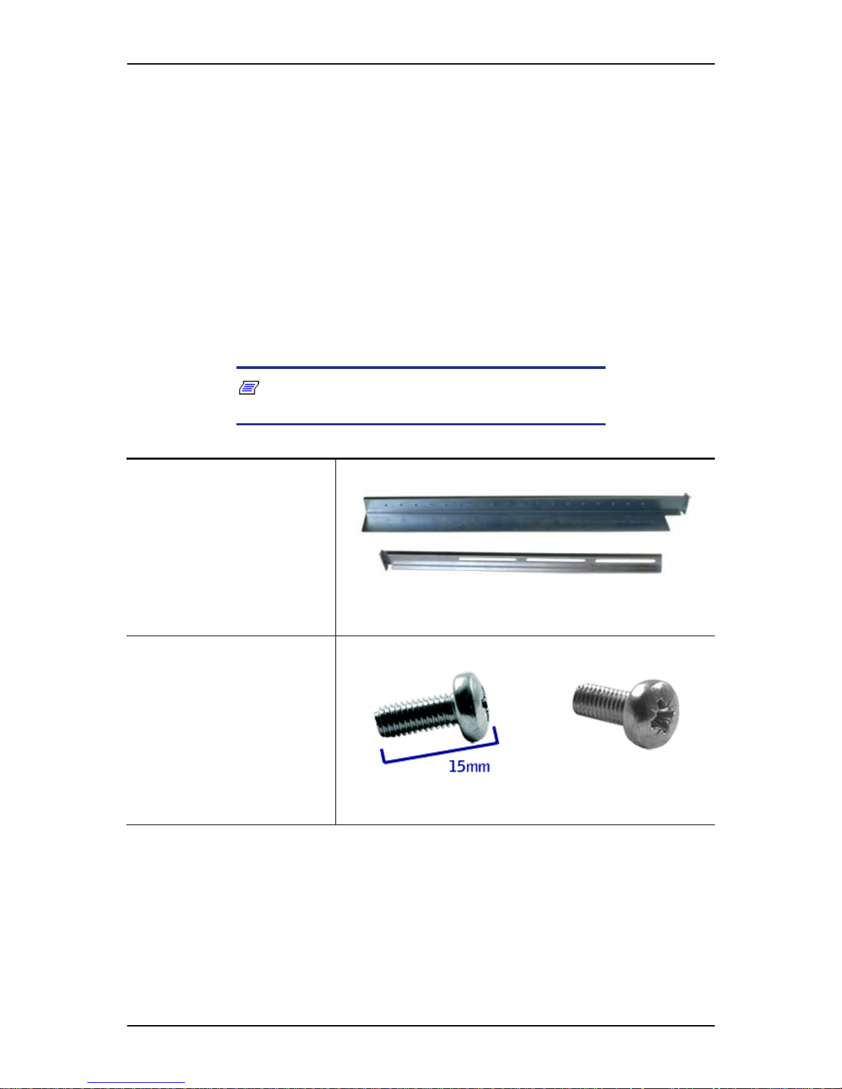
User Guide
94
www.bull.com
NovaScale T830 E1 Rack Installation Kit
Assembly
This section provides the assembly instructions for mounting the server into a standard
19-inch rack cabinet.
Unpacking the Rack Installation Kit
Although the rack installation kit is inspected and carefully packaged at the factory,
damage may occur during shipping. Follow these steps for unpacking.
1. Visually inspect the shipping containers; notify your carrier immediately of
any damage.
2. Carefully remove the rack mounting hardware and verify the parts.
Note: The quantities noted below are subject to change
without notice.
2 sets of support rail assemblies (1 front and 1 rear part for
each)
Figure 60: Rail assembly front and rear parts
(right side shown)
6 (minimum) self-tapping
screws (TCB M5) for support
rails front and rear parts
assembling
Figure 61: Self-tapping screws
Page 95
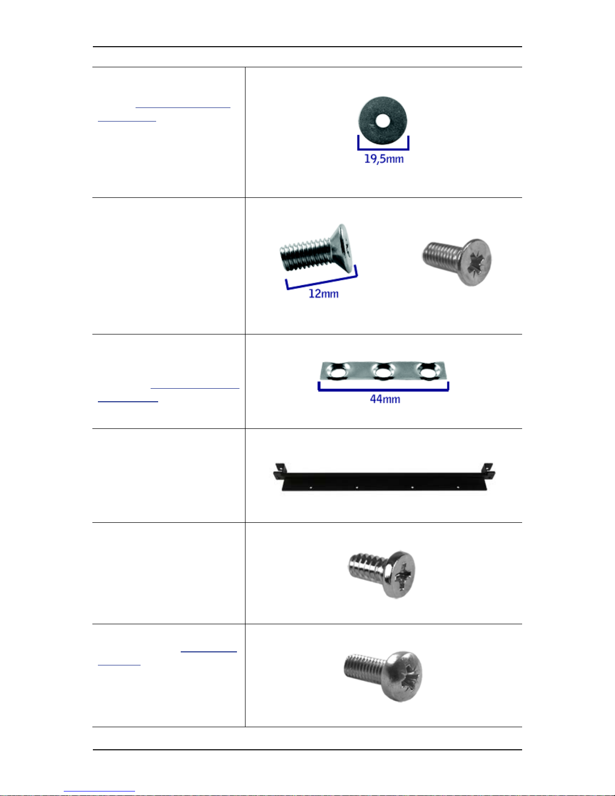
User Guide
95
www.bull.com
6 (minimum) washers, to be
used with the 6 self-tapping
screws ("Figure 61: Self-tap-
ping screws")
Figure 62: Washers for the self-tapping screws
8 flange head screws (M5x12)
used to fix the support rail
assemblies to the rack
Figure 63: Flange head screws
4 washer plates, to be used
with the flange head screws to
fix the support rail assemblies
to the rack ("Figure 63: Flange
head screws")
Figure 64: Washer plates
Filler
Figure 65: Filler
4 flange head screws, used to
fix the filler to the top cover
Figure 66: Flange head screws
2 Screws M5x16, to be used
with the washers ("Figure 68:
Washers") to fix the filler to
the mounting rails
Figure 67: M5x16 screws
Page 96
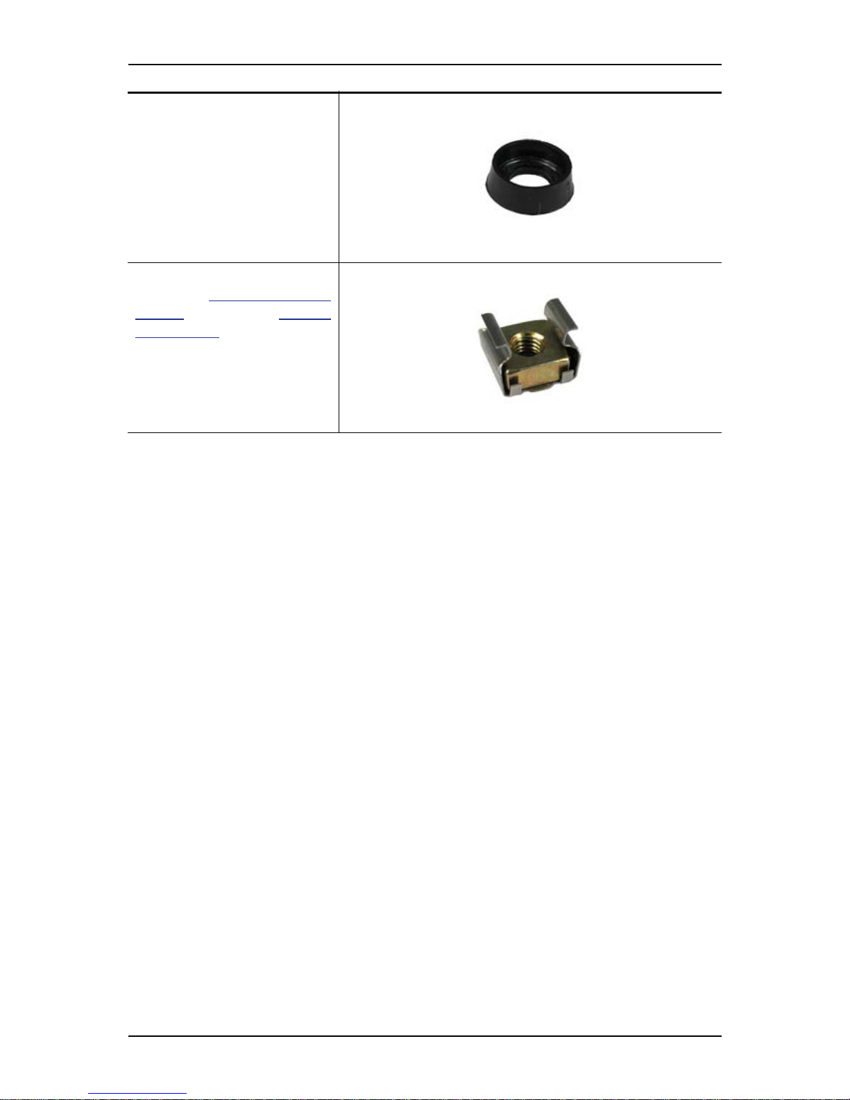
User Guide
96
www.bull.com
If some of the parts listed above are missing or if the hardware is damaged, notify your
server representative.
2 Washers for the M5x16
screws
Figure 68: Washers
2 Caged nuts, to be used with
the screws ("Figure 67:
M5x16
screws" ) and washers ("Figure
68: Washers") to fix the filler
to the mounting rails
Figure 69: Caged nuts
Page 97
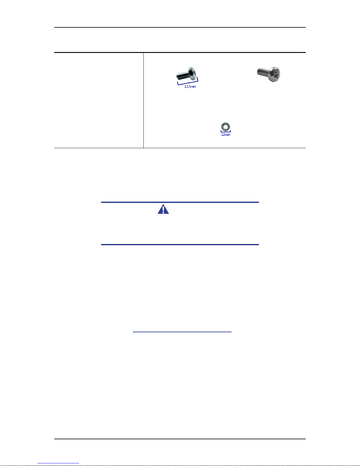
User Guide
97
www.bull.com
Additional Parts for Future Use
Before You Begin
Before you begin, please review the following cautions, warnings, and general
guidelines.
Warning
Be sure that power to the system is turned off and unplugged.
All voltage is removed only when the power cords are
unplugged.
■ Avoid excessive vibration and shock. Dropping an electronic component can cause
serious damage.
■ Do not disconnect or remove parts other than those specified in the procedure.
■ Do not touch I/O connector pins.
■ All screws are Phillips-head, unless otherwise specified.
■ On completion of any assembly or reassembly, perform a power-on test. If a fault
occurs, verify that the assembly or reassembly was performed correctly. If the
problem persists, see “Solving Problems” on page 264.
Static Precautions
An electrostatic discharge (ESD) can damage disk drives, option boards, and other
components. You can provide some ESD protection by wearing an anti-static wrist
strap attached to chassis ground when handling system components.
Electronic devices can be easily damaged by static electricity. To prevent damage, keep
them in their protective packaging when they are not installed in your system.
8 (minimum) screws (TCB
M5)
Figure 70: Screws
8 (minimum) washers
Figure 71: Washers
Page 98
User Guide
98
www.bull.com
Assembly
The following subsection describes how to assemble your rack-mount server into a
standard 19-inch rack cabinet.
Before you begin select an appropriate location in your rack cabinet for the rack-mount
server. To improve rack stability, mount heavier items towards the bottom of the rack
cabinet. If the rack is a stand-alone unit and the rack is more than 75% filled with
components, consider installing an optional stabilizer kit.
Note: When planning your system configuration for the rack
cabinet you should consider the length of the cables that interconnect system components.
Warning
■ ANCHOR THE EQUIPMENT RACK: The equipment rack must be
anchored to an unmovable support to prevent it from falling
over when one or more servers are extended in front of it on
slide assemblies. The anchors must be able to withstand a
force of up to 113 kg (250 lbs). You must also consider the
weight of any other device installed in the rack.
■ MAIN AC POWER DISCONNECT: You are responsible for install-
ing an AC power disconnect for the entire rack unit. This
main disconnect must be readily accessible, and it must be
labelled as controlling power to the entire unit, not just to the
server(s).
■ GROUNDING THE RACK INSTALLATION: To avoid the potential
for an electrical shock hazard, you must include a third wire
safety grounding conductor with the rack installation. If a
server power cord is plugged into an AC outlet that is part of
the rack, then you must provide proper grounding for the
rack itself. If server power cords are plugged into wall AC
outlets, the safety grounding conductor in each power cord
Page 99

User Guide
99
www.bull.com
provides proper grounding only for the server. You must
provide additional, proper grounding for the rack and other
devices installed in it.
Caution
Temperature: The operating temperature of the server, when
installed in an equipment rack, must not go below 5 °C or rise
above 35 °C. Extreme fluctuations in temperature can cause a
variety of problems in your server.
Ventilation: The equipment rack must provide sufficient airflow
to the front of the server to maintain proper cooling. It must also
include ventilation sufficient to exhaust a maximum of 4,100
Btu's per hour for the server. The rack selected and the
ventilation provided must be suitable to the environment in
which the server will be used.
Note: For vertical reference, every three screw holes on the
rack vertical mounting rail are equal to 1U (1.75 inc hes ) .
Mounting holes in the vertical rails of equipment racks are commonly spaced in a 5/8 x 5/8 x 1/2-inc h sequence. Perform the
following steps carefully; brackets must be moun ted with precision to allow room for the next server you install in a rack.
Assembling the Front and Rear Parts of Support Rails
The support rails are made of a front and a rear part. Those two parts may be adjusted
to fit the distance between the front and rear vertical rails of the rack.
1. Assemble the front (A) and rear (B) parts of the right support rail with 3 self
tapping screws (C) and 3 flat washers (D).
Note: When using self-tapping screws, we recom mend you
tighten the screw for 3 quarters of a turn, and loosen for 1
quarter. Repeat this cycle until the screw is completely
tightened.
Page 100
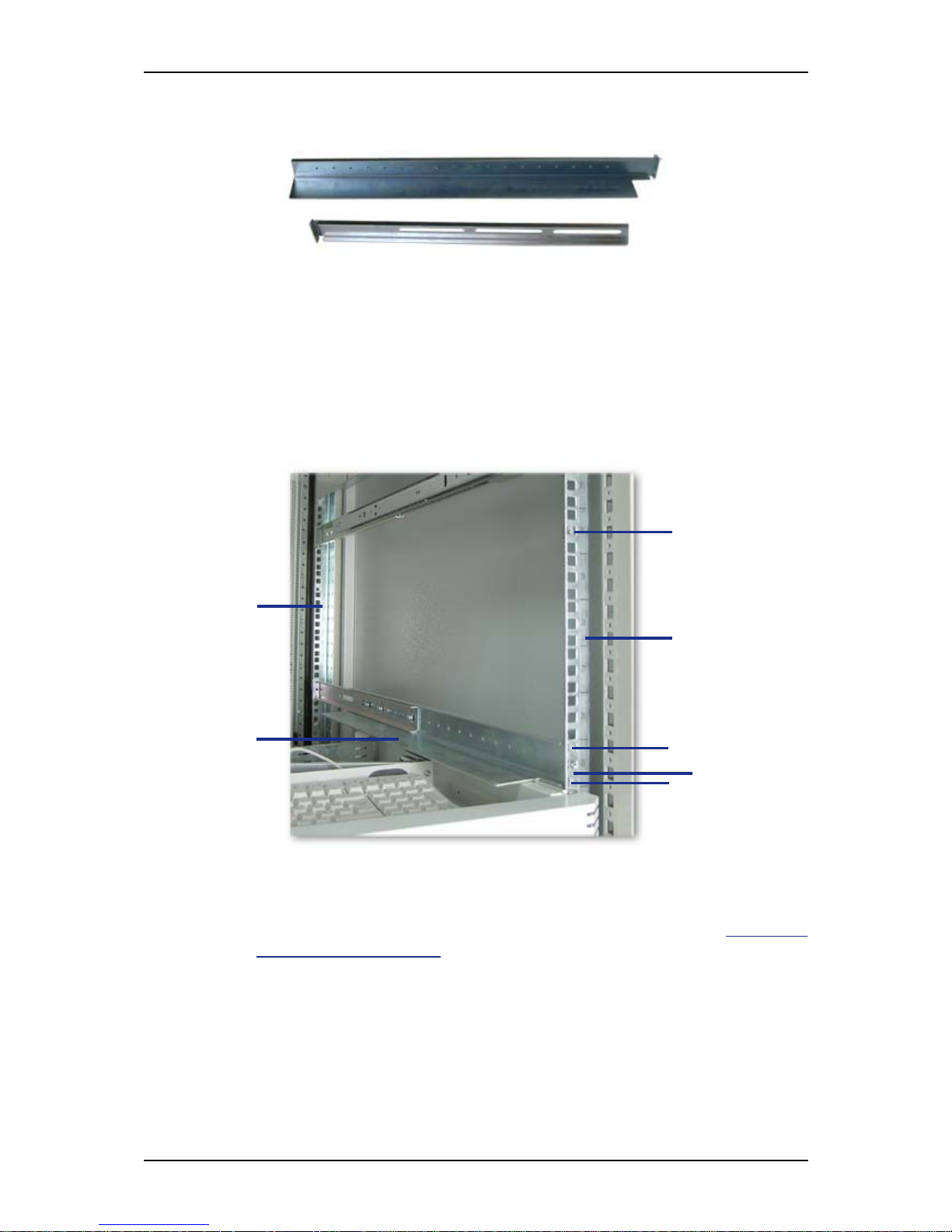
User Guide
100
www.bull.com
2. Adjust the total length to fit the distance between the front and rear vertical
rails of the rack before securing the screws.
Figure 72: Right support rail front and rear parts
3. Assemble the left support rail the same way.
Installing the Support Rails
1. Install the right support rail (A) as shown in illustration.
2. Secure the rail to the front (B) and rear (C) vertical mounting rails with two
flange head screws (D) and the washer plate (E).
Figure 73: Installing the right support rail
3. Insert one caged nut (F) as shown in the figure above, in the middle hole of the
sixth U. Insert the caged nut in the front mounting rail as follows (see "Figure
74: Inserting a caged nut"):
■ Position the caged nut on the inside of the front vertical mounting rail.
■ Hook the side lip of a caged nut into the square hole in the rail.
A
B
C
D
D
E
F
 Loading...