

Novar Savvy Service Manual
Savvy® Service Manual
Introduction
The Savvy® functions as both a system network manager
and intelligent local controller in Novar’s Logic One
Automated Building Control System by combining the
capabilities of an Executive Processor and an Input/Output
Module. The Savvy can be configured to meet complex
control requirements, regardless of facility size and/or
special monitoring and data collection requirements.
This document describes the Savvy, provides instructions
for replacing the electronics assembly and for taking a
milliamp reading, and provides troubleshooting guidelines
for:
Network Communications Loss
§
Telephone Communications Loss
§
Analog Light Sensor Faults
§
Outdoor Temperature Sensor Faults
§
Analog Sensor Faults
§
Phase Loss Faults
§
Outputs
§
Digital Inputs
§
Pulse Meter Faults
§
®
WARNING! Before performing any of the operations outlined in
this document, review the Note and the Warning that
appear at the beginning of this manual.
Precautions
NOTE! To perform any of the operations outlined in this manual,
a person must meet both of the following qualifications:
n Be a licensed electrician or a licensed HVAC
technician.
n Have experience in troubleshooting building
automation and HVAC controls.
DOC. #TD-0240 11/30/06 1

Savvy® Service Manual
WARNING! Some service and maintenance checks in this manual
require that the unit’s power be turned on. Multiple
voltages at the rooftop unit present an electrical shock
hazard that can cause injury or death. Before attempting to
service Novar equipment, turn off power to the rooftop
unit at the disconnect switches. When performing the
service checks that require power, turn on the power as
necessary but be aware that the electrical shock hazard
exists. No one should perform the operations outlined in
this manual unless he or she meets both of the
qualifications specified above and is trained and
experienced in working with the following voltages:
n 24-VDC
n 24-VAC
n 110-VAC
n 208-VAC
n 277-VAC
n 480-VAC
Make sure that the 24-VAC power wiring is connected to
a dedicated transformer. No other devices (including the
outputs) should be powered by the transformer connected
to the Savvy.
Description
Do not ground the transformer for this module on the
secondary side.
Make sure that the Savvy power cannot be switched off
accidentally. the Savvy requires continuous power for
proper operation.
The Savvy is mounted on a baseplate and powered by a 24-VAC, Class 2,
transformer connected to a 120-VAC source. A second 120-VAC circuit powers
the transformer for the outputs. The output terminal strip is rated 24-VAC, 2
amps, pilot duty. The outputs are controlled by low voltage triacs or relays.
The Hand/Off/Auto (HOA) switches are used for override for each output.
The remote override terminal strip allows remote, timed, or override capabilities
that are software-defined and driven. The remote override panel uses a
momentary dry contact.
A 22-gauge (minimum), 2-wire, shielded cable must be used for module network
communications. Cable length should not exceed 5000 feet.
The Class 2 input terminal strip is the termination point for 4- to 20-milliamp
current loop (analog) or contact closure (digital) inputs. All digital inputs must
be dry contact.
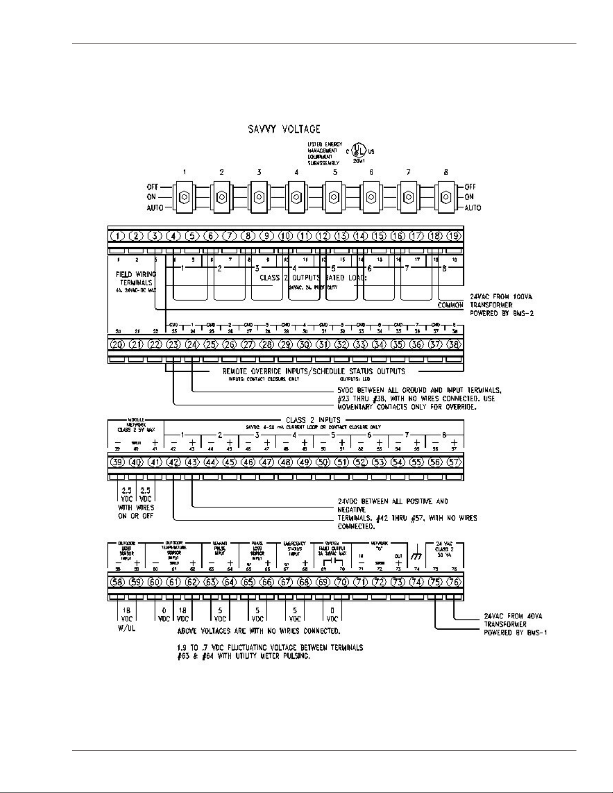
The Savvy draws 1.2-amp current. Terminals 75 and 76 (shown in Figure 1) are
used for the 24-VAC power connection. Terminals 39, 40, and 41 (see Figure 1)
are used for the Module Network Communications connections (2.5 VDC).
2 DOC. #TD-0240 11/30/06
Savvy® Service Manual
Figure 1. Savvy transition board
DOC. #TD-0240 11/30/06 3
Savvy® Service Manual
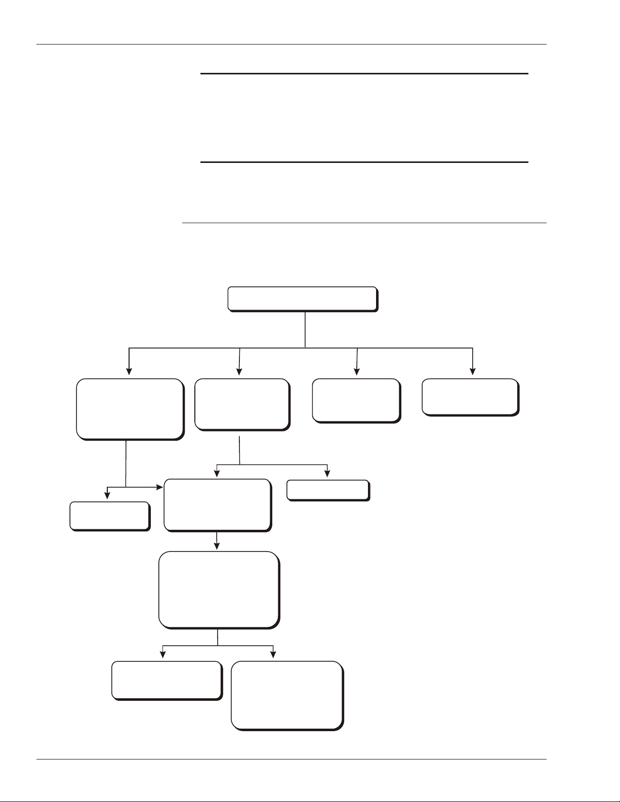
Check all rooftop units (RTUs) and IOMs to
determine where communication loss is occurring.
Remove the bottom cover from the
Savvy to access the transition
board, disconnect the wires on
Terminals 39, 40, and 41, and
remove and reinstall the Savvy
electronics assembly.
Are the IOMs communicating?
Use the Communications Loss
troubleshooting procedures
provided in the appropriate
ETM Service Manual.
Network Communications Loss
Troubleshooting Chart
NO
If no RTUs or IOMs
are communicating
If no RTUs are communicating
but all IOMs are communicating
If some RTUs are communicating
and IOMs are communicating
intermittently
If some RTUs are communicating
and all IOMs are communicating
Check the RTUs/ETMs, circuit
breakers, disconnects, and
smoke detectors.
Are the RTUs/ETMs powered
and the IOMs communicating?
Make sure the RTUs/ETMs
are addressed correctly.
Refer to the appropriate
ETM Service Manual for
address information.
Replace the Savvy with
an identical model and
make sure it operates.
Remove the bottom cover from the
Savvy to access the transition
board, disconnect the wires on
Terminals 39, 40, and 41, and meter
the wires + to shield and – to shield.
Is 2.5 VDC present?
Power up the RTUs or
repair them, as necessary.
If the voltage on the wires is incorrect,
check the communication voltage at
each ETM. Start at any RTU and
remove the communication wires from
the ETM communication terminals.
Meter the terminals between + to
shield and – to shield.
Is 2.5 VDC present on the terminal
strip and terminals?
If ETMs are powered/
IOMs are communicating
If none of the RTUs
have power
YES
If there is no voltage on the terminal
strip, replace the ETM with an
identical model and make sure the
replacement operates properly.
If 2.5 VDC is present on the
terminals, reconnect the wires and
proceed to the next RTU. Continue
to meter each unit.
If 2.5 VDC is present on all terminals
on each ETM, the communication
wire is shorted. Check each wire for
a short to ground.
Terminal Strip Terminals
NOTE! The Savvy is a Class 2 low-voltage device. Do not connect
120 VAC to any terminal. Do not connect AC voltage to
Module Network Class 2 communication terminals. Do not
connect DC voltage to module output Class 2 terminals (the
triacs will not work). Do not ground the transformer for
this module to the secondary side.
The Network Communications Loss and Telephone Communications Loss
troubleshooting charts included in this document can be used to troubleshoot
communications loss.
4 DOC. #TD-0240 11/30/06
Savvy® Service Manual
NO
YES
NO
YES
NO
YES
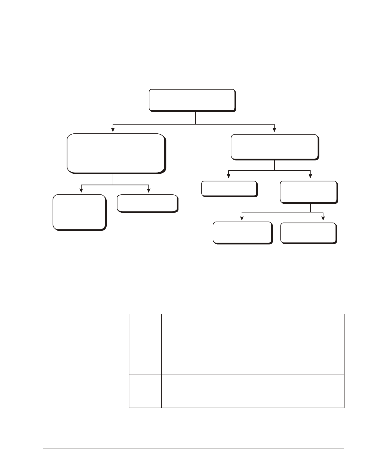
Check the status of the lights on the store
override panel located next to the Savvy.
Does the Savvy have power?
Remove the bottom cover of the Savvy to
access the transition board, unplug the Savvy
phone line from the jack on the transition board,
and plug the line into a single-line analog phone
to determine if the line is operational.
Is there is a dial tone?
Telephone Communications Loss
Troubleshooting Chart
NO
YES
Push down firmly on the top part of the
Savvy to make sure it is plugged into the
base.
Verify that communication
has been restored.
Meter Terminals 75 and 76
on the transition board.
Is 24-VAC present?
Plug the line back in. If
the Savvy still does not
answer, replace the
Savvy and make sure the
replacement operates
properly.
Make arrangements to have
the telephone line repaired.
Replace the Savvy and
make sure the replacement
operates properly.
Check the Savvy
transformer and BMS #1
breaker for power.
Replacing the Savvy
Electronics Assembly
DOC. #TD-0240 11/30/06 5
If the troubleshooting procedures provided in this document indicate that the
Savvy should be replaced the following procedure should be used.
Step Procedure
1 Remove the bottom cover from the Savvy:
2 Move all lighting HOA toggle switches to the center position to
Loosen the two Allen screws at the bottom of the Savvy.
§
Pull the bottom of the cover away from the Savvy and down.
§
ensure that all lighting loads stay on.
3 Check to see if an Ethernet® cable is connected to the Savvy
electronics and, if applicable, disconnect it.
continued
 Loading...