

Page 1
KMB systems, s.r.o.
Dr. M. Horákové 559, 460 06 Liberec 7, Czech Republic
tel. +420 485 130 314, fax +420 482 736 896
email : [email protected], internet : www.kmb.cz
10/2013
Remote Controlled Target PF and Remote Controlled
Outputs Compensation Systems Based on Novar Line
Power Factor Controllers
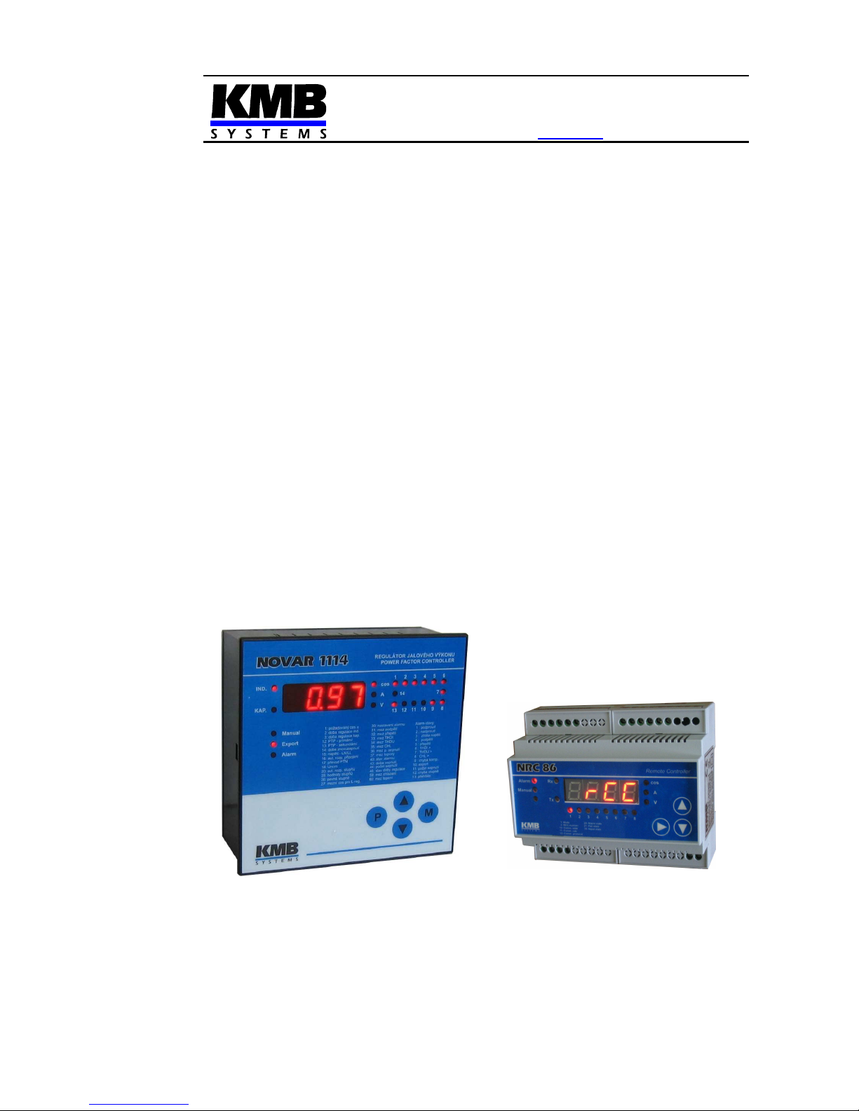
NOVAR-1xxx NRC Power Factor Controller
NRC 86 Remote Controller
Firmware v. 1.8 ( Novar ) / 1.0 ( NRC86 )
Operating Manual
Page 2

Novar-NRC KMB systems
2
LIST OF CONTENTS
1. APPLICATION..................................................................4
1.1 Remote Controlled Target Power Factor Compensation Systems ..................................................4
1.2 Remote Controlled Outputs Compensation Systems .......................................................................4
1.3 History of Firmware Versions ..............................................................................................................4
1.4 Manual Structure...................................................................................................................................4
2. THE „NOVAR1XXX NRC“ SPECIAL VERSION POWER
FACTOR CONTROLLERS......................................................6
2.1 Operation ...............................................................................................................................................6
2.1.1 Remote Controlled Power Factor (Cosinus) Mode – the „RCC“ Mode...........................................6
2.1.2 Remote Controlled Outputs – the „I/O“ Mode.................................................................................8
2.2 Parameters 01(07) – Target PF for Metering Rate 1(2) / Actual Remote Controlled Target PF......8
2.2.1 Parameter 01..................................................................................................................................8
2.2.2 Parameter 07..................................................................................................................................8
2.3 Parameters 30 – Alarm Setting, 40 – Alarm Status ............................................................................9
2.3.1 Alarm No. 6 – Undercurrent Alarm with Adjustable Limit or Alarm by Import with Adjustable Limit
and Fixed Outputs Release at Export..............................................................................................................9
2.3.1.1 Undercurrent Alarm with Adjustable Limit..................................................................................9
2.3.1.2 Alarm by Import with Adjustable Limit and Fixed Outputs Release at Export ............................9
2.3.2 Alarm No. 15 – Remote Control Failure .......................................................................................10
2.4 Parameters 50, 51, 52 – Instrument Address, Communication Rate and Communication
Protocol / NRC86 response timeout ...............................................................................................................11
2.5 Parameter 53 – Remote Control Mode ..............................................................................................11
2.6 Parameters 80,81 – Remote Controlled Target PFs and Remote Controlled PF Serial Number .13
3. NRC 86 REMOTE CONTROLLER................................. 14
3.1 Description ..........................................................................................................................................14
3.2 Operation .............................................................................................................................................15
3.2.1 Remote Controlled Power Factor (Cosinus) Mode – the „RCC“ Mode.........................................15
3.2.2 Remote Controlled Outputs – the „I/O“ Mode...............................................................................15
3.2.3 Manual Mode................................................................................................................................15
3.3 NRC86 Remote Controller Parameters .............................................................................................15
3.3.1 Parameter 01 – Remote Control Mode ........................................................................................15
3.3.2 Parameter 02 – Remote Controlled PF Serial Number ................................................................16
3.3.3 Parameter 05 – Number of Processed Outputs (in I/O mode) .....................................................17
3.3.4 Parameter 06 – Daisy-Chain Communication Mode („Cascade“) ................................................17
3.3.5 Parameters 10, 11, 22 – Instrument Address, Communication Rate and Communication Protocol17
Page 3

Novar-NRC KMB systems
3
3.3.6 Parameter 20 – Alarm Status.......................................................................................................17
3.3.7 Parameter 21 – Instrument Failure Status ...................................................................................17
3.3.8 Parameter 30 – Logic Inputs Status.............................................................................................18
3.4 Installation ...........................................................................................................................................18
3.4.1 Power Supply ...............................................................................................................................18
3.4.1.1 24 VDC Power Supply Version................................................................................................18
3.4.1.2 230 VAC Power Supply Version ..............................................................................................18
3.4.1.3 Protection.................................................................................................................................18
3.4.2 Logic Outputs ...............................................................................................................................18
3.4.3 Logic Inputs..................................................................................................................................19
3.4.4 Communication Interface .............................................................................................................19
4. PUTTING IN OPERATION..............................................20
4.1 Remote Controlled Target PF Compensation Systems ..................................................................20
4.2 Remote Controlled Outputs Compensation Systems .....................................................................21
5. CONNECTION EXAMPLES............................................23
6. NRC86 REMOTE CONTROLLER TECHNICAL
SPECIFICATIONS..................................................................26
7. MAINTENANCE, TROUBLESHOOTING .......................27
Page 4

Novar-NRC KMB systems
4
1. Application
1.1 Remote Controlled Target Power Factor Compensation Systems
When connecting major sources to medium voltage network, a remote control of reactive power is
often required. One possibility is to control target power factor using pulse signals from distributor (eg,
transmitted via a GPRS modem). Such equipped compensation systems can be implemented using
the Novar1xxx NRC power factor controller and the NRC86 remote controller.
1.2 Remote Controlled Outputs Compensation Systems
Alternatively, the NRC86 controller in combination with the Novar1xxx NRC power factor controller can
be used for remote controlled outputs compensation systems.
In practice, there may be cases where compensation capacitors must be placed at great distance from
the measuring current transformer (CT). Since the maximum length of the wires to the CT is limited
due to the limited maximum loop impedance, in some cases the power factor controller cannot be
installed in a switchboard with capacitors but at the measurement point near the CT. In such cases, it
is necessary to install a multi-core power cable connecting the controller with capacitor contactors. If,
for technical or other reasons, this solution is impossible and there exists a suitable communication
channel (cable or other media) between the points, the NRC86 remote controller can be used for
driving the capacitor contactors.
1.3 History of Firmware Versions
Novar 1xxx NRC
version date of release note
1.3 10/2010 - basic version
1.4 8/2011 - THDI alarm replaced with adjustable current limit undercurrent
alarm ( parameters 30, 40)
1.5 11/2011 - RCC/IO communication error fixed
1.6 09/2012 - combined RCC and I/O operation and multiple NRC86 units
performance support added
1.7 04/2013 - “Alarm by import with adjustable limit and fixed outputs release at
export" function added
1.8 10/2013 - PF display error at undercurrent alarm activation correction
NRC 86
version date of release note
0.1 10/2010 - basic version
0.2 01/2011 - „I/O“-mode for two NRC86 units added
0.3 04/2011 - general I/O device feature added
1.0 09/2012 - combined RCC and I/O operation and multiple NRC86 units
performance support added
1.4 Manual Structure
This Operating Manual describes the NRC86 remote controller and the Novar1xxx NRC controller’s
specific features only. At least basic knowledge of Novar line power factor controllers is necessary for
understanding it.
Page 5

Novar-NRC KMB systems
5
Detailed description of the Novar power factor controllers can be found on the manufacturers website
at www.kmbsystems.eu .
Page 6

Novar-NRC KMB systems
6
2. The „Novar1xxx NRC“ Special Version Power Factor
Controllers
The „NRC“ special version is available for following Novar power factor controller (PFC) models :
1106, 1114, 1206, 1214 ( marking example : Novar1214 NRC). The 1414 and 1312 models can be
delivered with limited functionality only – see below.
The PFCs are equipped with a RS-485 communication interface and with the special version firmware
„0E“ that allow, in combination with the NRC86 remote controller, either a remote controlled power
factor operation mode or a remote controller outputs operation mode .
From point of view of hardware and installation, the „NRC“-version PFCs don’t differ from standard
PFC models (with exception of models Novar1414 NRC and Novar1312 NRC, see below) and detailed
description can be found at the standard Novar1xxx operation manual. The only difference is their
firmware – they are equipped with special version firmware „0E“. The PFCs are marked with the „0E“
code :
• on the panel of the controller at initial phase after supply voltage is applied. When the
firmware version is displayed the first two characters of displayed string „0E1.3“ stands for
special firmware version 0E, and the last two stands for basic firmware version 1.3.
• at firmware window of the product label on the rear panel of the controller. For example
marking „1.3/OE“ means basic firmware version 1.3 and the character after a slash mean
special version „0E“
The only limitation of this firmware version is that the Modbus communication protocol is not
supported. All of other features are the same as the standard version.
The Novar1414 NRC and the Novar 1312 NRC models differ, moreover, from the standard models by
not allowing automatic connection detection and automatic sections’ powers recognition. Therefore,
the type of connection (parameter No. 16) and individual sections’ power sizes (parameter No. 25)
must be entered manually.
2.1 Operation
2.1.1 Remote Controlled Power Factor (Cosinus) Mode – the „RCC“ Mode
The Novar1xxx NRC PFC (or several PFCs) is connected to the NRC86 remote controller through a
RS-485 communication link. Using additional parameters of the „0E“ special firmware the PFC can be
set up to the RCC-mode (Remote Controlled Cosϕ). After being set, the PFC periodically reads serial
number of remote controlled PF value in range 1 ÷ 5 from the NRC86 unit.
In the PFC it is possible to preset five PF values corresponding to the remote controlled PF serial
numbers. Default values are –0.95 / -0.97 / 1.00 / 0.97 / 0.95 , but they can be freely changed.
According this setting the PFC keeps preset target PF value that is dynamically controlled by the
remote controlled PF serial number from the NRC86 unit ( standard target PF value in parameter 01
has no meaning in this mode).
Simultaneously, other NRC86 units (up to six, i.e. seven units in total) in function of remote controlled
outputs (see below) can be connected to the communication link too.
Page 7

Novar-NRC KMB systems
7
Tab. 2.1 : Novar-1xxx NRC Additional and Affected Parameters
#
name range step default comment
1
(7)
target PF for
metering rate 1
(2)
actual remote
controlled
target PF
0.80 L ÷ 0.80 C
„EX.XX“ format indicates
remote controlled target PF
value in the „RCC“-mode
0.01 0.98 L
in the „RCC“-mode (see par. 53), depending
on the metering rate 2 parameter setting and
state, the actual value of target PF is defined
by setting of the „remote controlled target
PF“ (par. 80) and by actual state of the
„remote controlled PF serial number“ (par.
81)
6 metering rate 2
enable/disable
0 – 1 – E — 0
when the metering rate 2 parameter enabled
(value "1" or "E") and the "RCC"-mode (par.
53) enabled, PF control is carried out by the
„remote controlled target PF“ when the
metering rate 2 just active only (i. e. when
digital input activated or active power export
occurs ); for metering rate 1, the PF is
controlled by the target PF for metering rate
1 (par. 01), regardless to the „remote
controlled target PF“ value
30 alarm setting
0 / indication only / actuation
only / indication and actuation
— indication and
actuation
from
undercurrent,
voltage signal
absence or
section error
1... undercurrent
…
14 … external alarm
15 ... NRC86 connection loss
Alarm No. 15 is activated when no response
from the NRC86 unit occurs during approx. 20
seconds. The alarm actuation function is
intended mainly for the „I/O“-mode.
40 alarm
instantaneous
condition
„0“ indicates passive state, „1“ indicates active
state. Alarm numbering according par. 30.
50
instrument
address
1 ÷ 255 1 1
In the„RCC“- and a the„I/O“-mode the preset
value has no meaning. The fixed address 200
is used for communication with the NRC86
unit.
51
communication
rate
4800 – 9600 – 19200 Bd — 9600
In the„RCC“- and a the„I/O“-mode the value
must correspond to that of the NRC86 unit
52 communication
protocol
NRC86
response
timeout
KMB(P0)
0 – 1 – 2 – 3 – 8 sec
- KMB(P0)
0 sec
Modbus-RTU protocol cannot be set.
In the„RCC“- and a the„I/O“-mode (par. 53)
the parameter defines the NRC86 unit
response timeout in seconds.
53 remote control
mode
-(=off) / IO / IO. / RCC / RCC.
/ RCCP
- -(=off)
- … remote control mode switched off comm. interface available for standard
remote monitoring (protocol KMB only)
- IO … „I/O“-mode only (with up to 7 NRC86s)
- IO. … „I/O“-mode with actual PFC state
broadcast
- RCC … „RCC“-mode with optional
simultaneous „I/O“-mode (with up to 6
additional NRC86s)
- RCC. … „RCC“-mode with actual PFC state
broadcast
- RCCP … „RCCP“-mode (passive)
80 remote
controlled
target PF No. 1
÷ 5 ( in
„RCC“-mode )
0.80 L ÷ 0.80 C
0.01 1. = 0.95 C
2. = 0.97 C
3. = 1.00
4. = 0.97 L
5. = 0.95 L
individual remote controlled target PF values
EC1÷÷÷÷EC5 corresponding to remote
controlled PF serial number (par. 81) can be
set in a side branch
81 remote
controlled PF
serial number
( in „RCC“mode )
1 ÷ 5
1 3
the value is periodically read from the NRC86
unit
- slowly flashing dec. point indicates off-line
state; the value displayed corresponds to the
last read value
- slowly flashing dec. point indicates default
state 3 ( at long time off-line state )
Page 8

Novar-NRC KMB systems
8
2.1.2 Remote Controlled Outputs – the „I/O“ Mode
The Novar1xxx NRC PFC is connected to the NRC86 remote controller (optionally to more of such
controllers) through a RS-485 communication link. Capacitor (or choke) contactors are not connected
to the PFC outputs but to corresponding outputs of the NRC86 controller(s).
Using additional parameters of the „0E“ special firmware the PFC can be set up to the I/O-mode
(Input/Output). Then the PFC output state is periodically transmitted to the NRC86 controller(s) and its
outputs state „copies“ the PFC outputs state. The outputs refresh speed is between 3 ÷ 10 times per
second if a transparent communication medium ( i.e. a medium with no transmission delay) is used (it
depends on preset communication rate and remote control mode). If usual metallic cable is used
maximum distance between the PFC and the NRC86 unit is up to 1 km, but it can be nearly unlimited
for suitable wireless media.
Up to seven NRC86 units can be connected. At each of the units you can set how many outputs to
process (i.e. how many of its outputs are controlled by the PFC outputs); then other outputs of the
PFC are processed by other NRC86 units. By this you can control outputs which are spatially spread
within reach of the communication line.
Desired remote controlled mode ( either the „RCC“ or the „I/O“ ) can be set using additional
parameters according Tab. 2.1°. Essential matters that differ from standard version are bolded.
Significant parameters detailed description follows.
2.2 Parameters 01(07) – Target PF for Metering Rate 1(2) / Actual Remote
Controlled Target PF
2.2.1 Parameter 01
If the remote control mode (par. 53) is switched off or if the metering rate 2 control (par. 06) is
enabled, parameter 01 has usual meaning, i.e. preset target PF value ( for metering rate 1).
If any of RCC-modes is set and the metering rate 2 control is disabled simultaneously, the target
PF is remote controlled by external NRC86 unit. In such case an actual value of remote controlled PF
with preceding „E“ character is displayed in parameter 01 ( for example E0
E0E0
E0.97
9797
97 ). This value cannot
be edited in parameter 01; it is defined by preset value of remote controlled target PF in parameter 80,
corresponding to actual state of remote controlled PF serial number. This serial number ( in range 1 ÷
5 ) is periodically read from theNRC86 unit and its value can be checked in parameter 81.
Thus the PFC controls PF to one of preset values in parameter 80. Usual value of parameter 01, i.e.
standard target PF value for metering rate 1, has no meaning in the RCC-mode and it is not displayed.
But, if the metering rate 2 control (par. 06) is enabled, the parameter 01 has usual meaning - preset
target PF value ( for metering rate 1). Then, if the metering rate 2 is inactive actually, the parameter 01
target PF is used for PF control and the remote controlled target PF value is ignored.
2.2.2 Parameter 07
The standard meaning of this parameter is target PF for metering rate 2 (the second tariff). If the
metering rate control (parameter 06) is disabled its value has no meaning.
If the metering rate 2 control is enabled and the RCC-mode is off, target PF is defined by the
parameter 01 or 07 according actual state of the metering rate 2 control value.
Page 9

Novar-NRC KMB systems
9
If the metering rate 2 control is enabled and any of the RCC-modes is set simultaneously, the
target PF is remote controlled by external NRC86 unit only when the metering rate 2 (tariff 2) just
active. In such case, the actual value of remote controlled PF with preceding „E“ character is
displayed in parameter 07 ( in the same way as in the parameter 01 when the metering rate 2 control
disabled). The parameter 01 has in such case its usual meaning, i.e. preset target PF value for tariff 1.
Thus, if the tariff 2 just inactive, the PF is controlled by the parameter 01 value and the remote
controlled target PF value is ignored.
The tariff2 value is evaluated in the usual way: either by state dig. input (1) or export (E).
2.3 Parameters 30 – Alarm Setting, 40 – Alarm Status
2.3.1 Alarm No. 6 – Undercurrent Alarm with Adjustable Limit or Alarm by Import with
Adjustable Limit and Fixed Outputs Release at Export
At standard Novar 1xxx controllers, the alarm No. 6 is controlled by THDI value.
At the Novar 1xxx NRC controllers, the alarm is not evaluated. The alarm No. 6 has one of following
meanings depending on its setting :
2.3.1.1 Undercurrent Alarm with Adjustable Limit
This is in fact enhanced undercurrent alarm. Behaviour of the alarm corresponds to the alarm No. 1
(thus, it is controlled by Ieff value); furthermore, the undercurrent limit value in “per mille”(ppt, range 0
÷ 200 ppt) of nominal current (5A/1A according parameter 13 setting) can be set in parameter 33.
For this alarm behaviour, the alarm No. 1 must be set in the same way as the alarm No. 6.
The limit value setup example : CT ratio (par. 12,13 ) is set to 500/5A. We intend to set the
undercurrent limit to 15A. Nominal current corresponds to the CT primary value, i.e. 500A, one ppt of
this is 0.5A. So we set the parametr 33 to 15 / 0.5 = 30.
2.3.1.2 Alarm by Import with Adjustable Limit and Fixed Outputs Release at Export
For this alarm functionality, the actuation function of the alarm No. 1 must be (unlike the function
described above) switched off (usual value 0
00
0) and the actuation function of the alarm No. 6 must be
switched on (usual value 2
22
2), simultaneously. Then :
• The alarm No. 6 is triggered as soon as fifteen-minute average value of the active current
Iact is either positive (=import), or it is negative, but its absolute value is below the preset limit
in “per mille”(ppt, range 0 ÷ 200 ppt) of nominal current (5A/1A according parameter 13
setting) in parameter 33. During the check a hysteresis of +/-1mA is applied.
• When the actuation is triggered all of the fixed sections are set to their preset states. The
controller goes on operation with the remaining ones. If all of the sections are fixed the power
factor control is suppressed.
• As soon as the fifteen-minute average value of the active current Iact gets negative (=export)
and its absolute value exceeds the preset limit in the parameter 33, the alarm gets inactive.
At the same time, all of the sections preset as fixed ones are released for the control process,
i.e. they are considered as standard control sections.
• This alarm function setting is indicated by slowly flashing decimal points at the sections
pressed as fixed at the parameter 26, that denotes their conditional behaviour
Page 10

Novar-NRC KMB systems
10
Note 1 : The fifteen-minute average value of the active current Iact is not displayed, you can check
the actual value of the active current Iact only. So you must take in mind appriopriate delay in the
alarm activation and deactivation when checking its behaviour.
Note 2 : When this alarm is set , the undercurrent alarm (No. 1) is, as noted above, switched off,
necessarily. Therefore, the controller uses all of the sections but the fixed ones even if the measured
current drops to minimum. If you need the controller to set firmly defined combination of all the
sections when the alarm is activated, it is necessary to set as fixed all of the sections, not just those
that are to be fixed on, but the remaining sections as fixed off, as well.
The limit value setup example : Usually, it is necessary to set the current limit according required
active power threshold. CT ratio (par. 12,13 ) is set to 500/5A, type of measurement voltage (par. 15)
is phase-neutral ( U=LN
U=LNU=LN
U=LN), nominal voltage U
NOM
(par. 18) is 230 V. We intend to set the undercurrent
limit to correspond to the -5kW (export) of three-phase active power. Corresponding phase power is
-5 / 3 = -1.67 kW = -1670 W. As nominal voltage is 230V, corresponding phase current is 1670 / 230 =
-7.25 A (for phase-phase voltage, it must still be divided by √3). As one ppt of the current range is (as
in previous example) 0.5A, we set the parameter 33 to 7.25 / 0.5 =~ 15.
2.3.2 Alarm No. 15 – Remote Control Failure
For remote control mode state checking, alarm No. 15 was added :
Tab. 2.2 : Remote Control Failure Alarm
# condition description minimum delay
of
activation /
deactivation
actuation
15 remote
control
failure
loss of connection with the NRC86
unit/units ( some of the unit response
is incorrect or missing at all )
20 / 1 seconds disconnection of all
sections
As default, the remote control failure alarm is switched off and it is possible to switch it on if advisable.
If no remote controlled outputs connected the actuation function is not interesting; it is intended
especially for emergency disconnection of remote controlled outputs. When temporary interruption of
the connection between the PFC and the NRC86 unit/units appears, the situation will look as follows :
1. Approximately after 20 seconds of communication link fault the PFC disconnects all of
outputs step by step and it will stay in standby mode until the connection is restored.
2. The NRC86 remote controller(s) in the I/O-mode disconnects (simultaneously) all of its
outputs after approx. 30 seconds of the communication link fault duration.
3. After the connection is restored, the PFC returns back to to control mode and the NRC86
controller(s) outputs starts to copy the PFCs outputs state to its outputs again.
So it is ensured that no premature switching of more outputs on will occur and the reconnection delay
time preset in the PFC will be kept
Page 11

Novar-NRC KMB systems
11
2.4 Parameters 50, 51, 52 – Instrument Address, Communication Rate and
Communication Protocol / NRC86 response timeout
Parameter 50 specifies the instrument address for remote control and monitoring of the PFC with the
Retis ot the Envis program. But this function cannot be used in a remote control mode because the
communication link is reserved for connection with the NRC86 unit(s). So the parameter value has no
meaning in this mode (the PFC uses fixed addresses 200 and higher for communication with the
NRC86(s) ).
The communication rate ( parameter 51) must be set identically as the communication rate of the
NRC86 unit(s). It is recommended to use default value 9.6 kBd or, according local conditions ( cable
length, interference level, … ), it is possible to increase it if applicable. In the RCC mode the set value
is not critical, in the I/O mode the higher value can bring better performance.
Parameter 52 setting is relevant only when any remote control mode ( either the RCC or the I/O) is
activated in parameter 53. In such case it doesn’t specify the communication protocol as usual but it
defines maximum wait time for response from the NRC86 unit(s). For default value 0 the NRC86
response timeout is approx. 0.3 sec – this setting is suitable for transparent communication links ( that
have no transmission delay).
For non-transparent communication media (with transmission delay) such like radiomodems,
GSM/GPRS modems, LAN etc., it is necessary to set this parameter value to maximum wait time for
response from the NRC86 i seconds ( in range 1 – 2 – 3 – 5 – 8 ).
If the remote control mode is switched off the parameter 52 has its usual meaning – the type of
communication protocol. But as the „NRC“-version PFCs don’t support the Modbus protocol the value
is fixed to P0 (= KMB protocol ).
2.5 Parameter 53 – Remote Control Mode
With this parameter you can activate the so-called remote control mode. In this mode, the PFC
cooperates with a NRC86 control unit (or more units) interconnected with a serial interface. The
interface is used to full capacity during remote control mode and therefore remote monitoring and
control of the PFC with the Retis or the Envis program is not possible.
Tab. 2.3 : Parameter 53 – Remote Control Mode Setting Options
setting description note
--
----
--
remote control mode is switched off communication interface can be used for
PFC remote monitoring & control (Retis,
Envis)
i0
i0i0
i0
I/O-mode only with up to 7 NRC86 units
number of the units connected defined by
their setting
i0
i0i0
i0.
I/O-mode and actual PFC state
broadcast
actual PFC state is simultaneously
transmitted to the NRC86
rCC
rCCrCC
rCC
RCC-active mode driven by the 1st
NRC86 unit and optional simultaneous
I/O-mode with up to 6 additional NRC86
units
to be set at the „master“ PFC only
rCC
rCCrCC
rCC.
RCC-active mode with actual PFC state
broadcast
actual PFC state is simultaneously
transmitted to the NRC86
rCCP
rCCPrCCP
rCCP
RCC-passive mode
to be set at the „slave“ PFCs
Page 12

Novar-NRC KMB systems
12
In principle, one of two remote control modes can be activated - either the I/O or the RCC mode :
• RCC mode
The RCC mode (Remote Controlled Cosϕ) is designated for remote control of target power
factor value. Simultaneously, a remote controlled outputs can be driven by additional NRC86
units.
Basic RCC-mode, so called active, must be set at one of PFCs only connected to the NRC86
unit(s); this PFC then behaves as “master”, that means it controls data interchange on the
communication link; during this, actual states of the PFC outputs are transferred to additional
NRC86 units in case of simultaneous remote outputs control. If more PFCs connected to the
NRC86 unit, all of others must be set as „slaves“, that means to passive RCC-mode marked
as RCCP.
As soon as the mode is set, the master PFC starts to send commands to the NRC86 unit(s).
The unit (with address of 200 if more units connected) receives them, processes them and
sends confirmation back to the master PFC. The master PFC receives and processes the
NRC86 confirmation and this loop is repeated forever. The slave PFCs listen to
communication and receives the NRC86(s) answers (confirmations) only.
The (first) NRC86 confirmation contains so called remote controlled PF serial number - its
value can be checked parameter 81. According this value and remote controlled target PF
values preset in parameter 80 it evaluates actual target PF, displays it in parameter 01 and
controls the PF according its value.
If the first NRC86 unit respectively set and more units (up to six ) connected in “cascade”, the
response of the previous unit is always received by the next unit with address higher by one
and such units operate as remote controlled outputs as described below.
• I/O mode
The I/O mode (Inputs/Outputs) is determined for remote controlled outputs only. In this
mode, up to seven NRC86 remote controllers can be connected to a single PFC.
The data interchange between the PFC and the NRC86(s) runs in the same way as in the
RCC mode with one difference only – target power factor is not controlled by the NRC86, but
actual state of the PFC outputs is transmitted to the NRC86 unit(s) and so the PFC state
outputs are “copied” to the unit outputs.
So called daisy-chain communication can be set at the NRC86 unit. If set , the unit passes
each command to the next unit with address higher by one after processing it. At the last unit
in the cascade the daisy-chain communication must be switched off.
Next, a number of processed outputs can be set at each unit. It specifies how many of PFC
outputs to be received and “copied” to the unit outputs. At the next unit in the cascade you
can set number of processed outputs similarly; then remaining PFC outputs are processed,
i.e. those starting from the first PFC output not processed by the previous unit. Maximum
number of the units in cascade is 7.
Example : The 1st unit setting : address=200, daisy-chain comm =on, No. of processed
outputs=6; the 2nd unit setting : address=201, daisy-chain comm =on, No. of processed
outputs=4; the 3rd unit setting : address=202, daisy-chain comm =off, No. of processed
outputs=7. Then, at the 1st unit 1÷6 outputs, the PFC 1÷6 outputs will appear; the 2nd unit
1÷4 outputs will copy the PFC ouputs No. 7÷10; and finally, at the outputs 1÷7 of the 3rd
unit, the PFC outputs No.11 and higher will appear (up to 17, or to the PFC maximum
output).
Page 13

Novar-NRC KMB systems
13
In both of the remote control modes, actual state of the master PFC broadcast can be activated.
These options are identified with additional decimal point. When set, the PFC broadcasts its complete
actual state (all measured quantities actual values, outputs state etc.) during communication with the
NRC86 unit(s). Then, these values can be listed and viewed on the NRC86 unit (the first unit only in
case of the unit cascade) display in the same way as on the PFC display. It can be helpful during
installation or it can be optionally used for the PFC actual state monitoring by a third-party system
(program).
But if not necessary it is recommended to use remote control mode without PFC actual state
broadcast during common power factor compensation operation. At this setting, the remote control
commands are essentially shorter and due to this the data interchange is faster and more reliable.
Then actual PF value and the PFC alarm state only can be checked on the NRC86 display.
2.6 Parameters 80,81 – Remote Controlled Target PFs and Remote
Controlled PF Serial Number
These parameters are relevant only when any of the RCC-mode is active. Otherwise they are not
displayed.
In the RCC-mode , co called serial number of remote controlled PF is periodically transferred from the
(first) NRC86 unit to the PFC (or multiple PFCs). Its range is 1 ÷ 5 and actual value is displayed in
parameter 81with identification string „ECn“; for example, if its value is 2, the ECn2
ECn2ECn2
ECn2 string is
displayed.
If connection between the PFC and the NRC86 unit is interrupted, the PFC keeps last correctly read
value from the (first) NRC86 unit for approx. 30 seconds and during this indicates with slowly flashing
decimal point that the displayed vale is not actual. If the connection is not restored during approx. 1
minute, the serial number of remote controlled PF is set automatically to its default value 3. This state
is indicated with quickly (approx. three times per second) flashing decimal point.
The parameter is set to this default value automatically after the PFC startup and keeps it until
receives first actual value from the NRC86 unit.
In side branch of parameter 80 you can set five remote controlled target PFs EC-1
EC-1EC-1
EC-1 through EC-5
EC-5EC-5
EC-5,
corresponding to remote controlled PF serial number value. The PF range is the same as parameter
01 has, but it is not possible to set the value in angle degrees. Default values are –0.95 / -0.97 / 1.00 /
0.97 / 0.95 .
According this setting and actual value of remote controlled PF serial number, the PFC selects
corresponding PF from preset values EC
ECEC
EC-1
-1-1
-1 through EC-5
EC-5EC-5
EC-5, displays it in parameter 01 ( with
preceding “E” character) and uses it as actual target PF.
Page 14

Novar-NRC KMB systems
14
3. NRC 86 Remote Controller
The unit is designed for power factor compensation systems either with remote controlled PF or with
remote controlled outputs. The unit operates in combination with special version of Novar power factor
controller – Novar1xxx NRC.
The unit is available in various modifications. Typical models are :
Tab. 3.1 : NRC86 Remote Controller Typical Models
model configuration typical use
NRC86-85 24VDC
• 8 inputs 24 V DC
• 5 relay outputs, up to 400 V AC
• aux. voltage 24 V DC
remote controlled PF
NRC86-07 230VAC
• 7 relay outputs, up to 400 V AC
• aux. voltage 100 ÷ 300 V AC
remote controlled
outputs
3.1 Description
The front panel consists of a numeric display, indication LEDs and control keys.
Fig. 3.1 : NRC 86 Remote Controller
Remote Controller
71 2 3 4 5 6 8
20:
21: Fail state
30: Input state
Alarm state 1: Mode
2: RCC number
10: Comm. addr
11: Comm. rate
12: Comm. protocol
Rx
Tx
0 97
.
The unit design is based on the Novar1007D PFC hardware; therefore indication elements and
manipulation is the same or similar. Detailed description can be found at the PFC operating manual.
Indication LED meaning corresponds to the PFC. There are additional LEDs Rx and Tx indicating
receiving and transmitting bytes from / to communication link.
You can list through actual values and unit parameters using the ▲, ▼ buttons. For into/off a side
branch or for parameters editing, use the ► button. Following operations can be made in the same
way as with a Novar line PFC :
• actual PF value display, refreshed periodically from connected PFC; if actual PFC state
broadcast is set, not only the PF value, but all actual values measured by the PFC can be
displayed
• listing through parameters and editing them
• disabling or enabling of parameter editing
• manual control of the unit outputs in Manual mode
Page 15

Novar-NRC KMB systems
15
3.2 Operation
3.2.1 Remote Controlled Power Factor (Cosinus) Mode – the „RCC“ Mode
Up to five pulse signals can be connected to the NRC86 unit. A pulse of correct duration on one of
inputs 1÷5 is evaluated as target PF serial number request. The unit saves the number into its
memory and confirms by switching of appropriate output on ( this signal is transmitted back to the
supervising system for checking ).
The Novar1xxx NRC PFC (or several PFCs) periodically reads the target PF serial number from the
unit and uses appropriate preset target PF for compensation.
The instrument address (parameter 10) must be set to 200. If other NRC86 units for remote controlled
outputs connected too, the daisy-chain communication option (parameter 6 ) must be set at all of the
units in the cascade but the last one. The other units’ addresses in the cascade must be increasing by
one, i.e. 201, 202 etc.
3.2.2 Remote Controlled Outputs – the „I/O“ Mode
For such applications the NRC86-07 unit model is suitable. It has 7 outputs (and no input). For
compensation systems with more than 7 outputs, two NRC86-07 units are necessary. Optionally you
can use up to 7 units in cascade if you need to spread remote outputs spatially.
The unit is installed in a PF compensation capacitor ( or choke) switchboard. It must be interconnected
with distant Novar1xxx NRC PFC using a communication link. The capacitor (or choke) contactors
must be connected to the NRC86 unit outputs; the PFC outputs stay unconnected.
The address (parameter 10) of the first unit must be set to 200. If other NRC86 units connected, the
daisy-chain communication option (parameter 6 ) must be set at all of the units in the cascade but the
last one and their addresses must increase by one, i.e. 201, 202 etc.
With the parameter 5 the number of processed outputs in the unit can be set. The parameter is preset
to the maximum number of outputs of the unit, but it can be decreased to “N” – then, the unit outputs
O1 ÷ ON will follow the PFC outputs’ state starting from the first output that is not processed by the
previous unit.
Example : The 1st unit (address 200) is set to 4 processed outputs; the 2nd unit (address=201) is set to
6 processed outputs. Then, at the 1st unit O1÷O4 outputs the PFC 1÷4 outputs will appear and the 2nd
unit O1÷O6 outputs will copy the PFC ouputs No. 5÷10. The daisy-chain communication must be
activated at the 1st unit and deactivated at the 2nd unit.
3.2.3 Manual Mode
In the Manual mode, the NRC86 unit goes on receiving commands and answering to them, but the
unit outputs stay unchanged - they can be changed manually only in the same way as a Novar PFC
outputs.
3.3 NRC86 Remote Controller Parameters
3.3.1 Parameter 01 – Remote Control Mode
The remote control mode of the NRC86 unit is displayed in the parameter – it can be eitheri0
i0i0
i0
(remote controlled outputs) or rCC
rCCrCC
rCC (remote controlled PF).
Page 16

Novar-NRC KMB systems
16
The parameter value is controlled and refreshed with each command received from a Novar1xxx NRC
PFC, it is not necessary to set it manually. In case of power failure, the last valid value of the
parameter is stored in the unit memory and automatically loaded after the power restoration.
For testing purposes, the parameter value can be set manually too. But, for this it is necessary to
switch the remote control mode off firstly or simply disconnect the communication link temporarily.
3.3.2 Parameter 02 – Remote Controlled PF Serial Number
This parameter is relevant in the RCC-mode only. In other modes it is not displayed.
The remote controlled PF serial number can have value in range 1 ÷ 5. If since last unit powerup or
the unit initialisation at least one PF control request had come ( i.e. a valid pulse signal had appeared
at one of I1 ÷ I5 inputs ), the decimal point of displayed parameter value is dark.
The last valid parameter value is stored into the unit memory and automatically uploaded after the unit
powerup. The fact that the parameter value was reloaded from the unit memory is indicated with
flashing decimal point of displayed parameter value. The same indication is activated after manual
editing of the parameter value.
The decimal point gets dark as soon as the first valid PF control request on I1 ÷ I5 inputs appears.
Tab. 3.2 : NRC86 Remote Controller Parameters
#
name range step default comment
1 remote control
mode
IO / RCC - IO
set by PFC commands; manual setting for
testing purposes possible only when cooperating
PFC remote control mode is switched off or if
communication link is disconnected
2 remote
controlled PF
serial number (
in „RCC“-mode )
1 ÷ 5
1 3
relevant in the RCC-mode only ; not displayed in
the I/O mode
5 outputs
processed
0 ÷ MAX
1 MAX
relevant in the I/O mode only; in the RCC mode
automatically 0, parameter not displayed
6 daisy-chain
communication
mode
0 (off) / 1 (on) - 0
in case of cascade of units must be set on at all
of the units but the last one
10
instrument
address
1 ÷ 254 1 200
for cooperation with a Novar1xxx NRC PFC in
remote control mode must be set to 200 (or
higher in case of units cascade)
11
communication
rate
4800 – 9600 – 19200 Bd - 9600 Bd
must correspond to cooperating Novar1xxx NRC
PFC setting
12 communication
protocol
KMB(P0) / Modbus-RTU(P1) - KMB(P0)
for cooperation with a Novar1xxx NRC PFC in
remote control mode must be set to P0 (KMB)
20 alarm status -- / E / C - -
set by the NRC86 unit ; indicates type of alarm :
E … external alarm (= indicates cooperating
Novar1xxx NRC PFC alarm active state)
C … communication out of order (no Novar1xxx
NRC PFC commands received)
21 instrument
failure status
indicates E-00 for failure-free state
30 logic inputs
status
I1÷I8 logic inputs state :
i … 0 ( passive )
I… 1 (active )
Page 17

Novar-NRC KMB systems
17
3.3.3 Parameter 05 – Number of Processed Outputs (in I/O mode)
The parameter is relevant in I/O mode only (it is not displayed in RCC mode). It defines how many of
the unit outputs starting from O1 output will be used as remote controlled outputs.
As default, the parameter is preset to the maximum outputs of the unit type. If decreased other outputs
will stay unused.
In case of cascade of more units in the I/O mode, PFC outputs’ states starting from the first output not
processed by previous unit are copied to the next unit outputs starting from its output O1.
3.3.4 Parameter 06 – Daisy-Chain Communication Mode („Cascade“)
If more than one NRC86 units connected to a PFC all of the units but the last one must be set to the
daisy-chain communication mode (i.e. set to 1
11
1).
This mode must be switched off at the last unit in the cascade , i.e. set to 0
00
0.
3.3.5 Parameters 10, 11, 22 – Instrument Address, Communication Rate and
Communication Protocol
The address (parameter 10) of the first NRC86 unit cooperating with a Novar1xxx NRC PFC in remote
control mode must be set to value 200. In case of more NRC86 units in “cascade” every next unit
address must by higher by one than the previous unit address, i.e. 201, 202, etc.
The communication rate (parameter 11) must be set identically as the supervisory Novar1xxx NRC
PFC. It is recommended to use default value 9.6 kBd or, according local conditions ( cable length,
interference level, … ), it is possible to increase it if applicable. In the RCC mode the set value si not
critical, in the I/O mode the higher value can bring better performance.
Parameter 12, i.e. communication protocol, must be set to KMB protocol, i.e. P0
P0P0
P0.
3.3.6 Parameter 20 – Alarm Status
This parameter value is driven by a NRC86 unit itself. If the Alarm LED-diode flashes, the cause of
the alarm can be identified by the parameter value :
• E
EE
E … indicates supervisory Novar1xxx NRC PFC in alarm state
• C
CC
C … indicates missing or incorrect commands from supervisory Novar1xxx NRC PFC (
probably communication link failure )
3.3.7 Parameter 21 – Instrument Failure Status
The unit carries out self-diagnostic tests in regular intervals during its operation. You can check the
diagnostics’ results in this parameter.
It shows E-00
E-00 E-00
E-00 if no errors have occurred. If the value is other than zero, the unit has identified an
error. Such a condition does not necessarily mean the unit is out of operation — in such an event the
unit supplier must be contacted and told about the identification value of the type of error shown.
Using this value, a specialist will then decide about the method of solving the problem.
Page 18

Novar-NRC KMB systems
18
3.3.8 Parameter 30 – Logic Inputs Status
For logic inputs status and functionality checking actual state of all logic inputs I1 ÷ I8 is displayed in
the parameter. The inputs states are displayed in order from left to right (the leftmost is I1 , the
rightmost I8). Character representation is as follows :
iiii … 0 ( passive )
I
II
I… 1 ( active )
3.4 Installation
The NRC86 unit is designed for mounting on a DIN-35 bar. Maximum cross section area of connection
wires is 2.5 square millimetres.
Examples of unit wiring are shown below.
3.4.1 Power Supply
The unit requires supply voltage in the range as declared in technical specifications table for its
operation.
The power supply terminals are galvanically isolated from other unit circuits.
3.4.1.1 24 VDC Power Supply Version
Direct auxiliary voltage connects to terminals 17 (+) and 18 (-). The marked polarity of connection is
recommended only, in fact it is free.
Power supply voltage needs to be externally protected ( see chapter Protection below ).
3.4.1.2 230 VAC Power Supply Version
Alternating auxiliary voltage connects to terminals 16 (L) and 18 (N).
Power supply voltage needs to be externally protected ( see chapter Protection below ).
3.4.1.3 Protection
Article 6.12.2.1 in the EN 61010-1 standard requires that instrument must have a disconnecting device
in the power supply circuit (a switch — see installation diagram). It must be located at the instrument’s
immediate proximity and easily accessible by the operator. The disconnecting device must be marked
as such. A circuit breaker for nominal current of 1 amp makes a suitable disconnecting device, its
function and working positions, however, must be clearly marked (symbols “0” for power off and “I” for
power on in accordance with EN 61010–1).
3.4.2 Logic Outputs
The NRC86 unit can have up to 7 output relays (depending on unit model).
The relays’ contacts go to terminals 20 ÷ 26 ( O1 ÷ O7 ). The relays’ common contacts are connected
to terminal 19 ( OC).
The relays’ output contacts are internally wired with varistors.
Page 19

Novar-NRC KMB systems
19
3.4.3 Logic Inputs
The NRC86 unit can have up to 8 galvanically isolated logic inputs (depending on unit model).
The inputs are passive – a voltage of appropriate level ( specified in technical parameters, see below )
must be applied. For direct voltage inputs the applied voltage polarity is free. The input voltages must
be connected to terminals 29 ÷ 36 ( I1 ÷ I8 ), the inputs’ common pole to terminal 28 ( IC ).
3.4.4 Communication Interface
The NRC86 units are equipped with galvanically isolated communication interface in compliance with
RS-485 specification for interconnection with supervisory Novar1xxx NRC PFC ( or with other
instruments in general use).
Signal-to-pin configuration for RS-485 type line is shown in Tab. 3.2.
Table 3.2: communication line signal configuration
signal
terminal
TR 1
DATA A 2
DATA B 3
GND/C 4
The interface allows connecting up to 32 instruments at a distance up to about 1 kilometre.
Recommended cable is shielded twisted metallic double pair. Use one pair for DATA A and DATA B
signals and the second pair for GND/C signal interconnection.
RS-485 line requires impedance termination of the final nodes by installing terminating resistors for
communication distances of a few tens of metres and longer. Terminating resistors matching the
cable’s wave impedance are connected between terminals DATA A and DATA B. The unit has a builtin terminating resistor of 330 ohms. It is connected between DATA B-signal (terminal 3) and TRterminal (1) inside the unit. To install the resistor, simply interconnect terminals DATA A (2) and TR
(1).
If the communication cable is hundreds of meters long and in environments with electromagnetic
noise it is suitable to use shielded cable. The shielding connects to the PE (protection earth) wire at
one end of the cable.
Page 20

Novar-NRC KMB systems
20
4. Putting in Operation
4.1 Remote Controlled Target PF Compensation Systems
For remote controlled power factor the NRC86-85 24 VDC remote controller is needed. If remote
controlled outputs using additional NRC86 units in cascade necessary too it is better to use the
NRC86-07 230 VAC models with 7 outputs each for this task.
One or more (up to 32) Novar1xxx NRC PFCs can be connected to.
Commissioning procedure step-by-step :
1. Install the Novar1xxx NRC PFC (or multiple PFCs) according its Operation Manual.
2. Install the NRC86 units according the Installation chapter of this manual.
3. Interconnect the NRC86 units and the PFC(s) with a communication link. Install terminating
resistors on the link ends. Switch the units’ power supply on and set the communication link
parameters No. 10, 11 a 12 according the specification above, i.e. the first unit ( which runs in
the RCC mode) address to 200 and the next units to 201, 202, 203 etc., step-by-step.
4. Set daisy-chain communication mode ( parameter 6 to 1) at all of the units but the last one
and the last unit to 0.
5. Set number of processed outputs ( parameter 5 ) at all units operating as remote controlled
outputs.
6. Power up the PFC (or PFCs). Check communication rate ( p. 51), eventually set to
correspond to the NRC86 unit setting. In the parameter 30, clear the section failure alarm (
No. 12 to „0“ ) and set the remote control failure alarm No. 15 to value „S“or to „2“.
7. In the „master” PFC, set the RCC-mode in parameter 53. The PFC will start transmitting
commands and the NRC86 unit should answer. Now set the NRC86 response timeout in
parameter 52. For transparent communication links set the value to 0. For non-transparent
links set the value (in seconds) that corresponds to maximum transmission delay of the
communication loop. Check the remote control function :
• The Rx and Tx LED-diodes of the NRC86 units must flashing synchronously to the
running communication. In the parameter 01 of the first unit, the RCC mode must be
displayed, optionally installed other units should indicate the I/O mode. At the first
unit one of unit outputs O1 ÷ O5 corresponding to serial number of remote
controlled PF in parameter 02 must be switched on, optional other units should copy
the PFC outputs’ states on their outputs. The units should not indicate any alarm, or
the external alarm only can be active ( the alarm of supervisory PFC, transmitted to
the unit)
• The PFC(s) should not indicate the remote control failure alarm. In the parameter
81, the serial number of remote controlled PF corresponding to that of the NRC86
unit should be. In parameter 01, appropriate remote controlled target PF value with
preceding „E“-character must appear.
8. In case of multiple PFCs connected, all other PFCs but the „master” one must be set to the
passive remote controlled PF mode, i.e. the parameter 53 to value RCCP. Parameter 52
must be set to the same value as the „master” PFC is set.
Page 21

Novar-NRC KMB systems
21
9. Check and optionally change remotely controlled target PF values in parameter 80 of all
PFCs.
Finally, it is recommended to check functionality of the whole system : step-by-step apply a pulse on
the I1÷ I5 inputs of the NRC86 and check response of all connected PFCs.
4.2 Remote Controlled Outputs Compensation Systems
For these applications, the NRC86-07 230 VAC remote controller with 7 outputs is optimal. Up to 7 of
such NRC86 units depending of number of compensation system outputs (contactors) and required
spatial spread can be used.
Commissioning procedure step-by-step :
1. Install the Novar1xxx NRC PFC according its Operation Manual. Let its outputs unconnected.
2. Install the NRC86 units according the Installation chapter of this manual. Connect contactors
of steps No. 1 ÷ N1 to the first unit starting with its O1 output, where N1 is number of
processed outputs (parameter 5) in the unit. Similarly at the next and other units, connect
contactors of steps No. (ΣN+1) ÷ (ΣN +1+NX) to the unit outputs, where ΣN is sum of outputs
processed by previous units and NX is number of outputs processed by the unit No. X. The
common pole of the unit(s) outputs should be wired via a protection device of suitable rating
to the contactors auxiliary voltage.
3. Interconnect the NRC86 unit(s) and the PFC with a communication link. Install terminating
resistors on the link ends. Switch the unit(s) power supply on and set the communication link
parameters No. 10, 11 a 12 according the specification above – address of the 1st unit in
cascade must be set to 200 and others to 201, 202, 203 etc., if installed.
4. Set daisy-chain communication mode ( parameter 6 to 1) at all of the units but the last one
and the last unit to 0.
5. Set number of processed outputs ( parameter 5 ) at all of the units.
6. Now switch the units power supply temporary off.
7. Power up the PFC. Check communication rate ( p. 51), eventually set it to correspond to the
NRC86 unit(s) setting. In the parameter 30, clear the section failure alarm ( No. 12 to „0“ )
and set the remote control failure alarm No. 15 to value „2“.
8. In the PFC, set the I/O-mode in parameter 53. The PFC will start transmitting commands to
the NRC86 unit(s), but as they are switched off now the PFC will during several seconds start
indicating alarm no. 15 ( remote control failure) and will switch all of its outputs off. Now set
the NRC86 response timeout in parameter 52. For transparent communication links set the
value to 0. For non-transparent links set the value (in seconds) that corresponds to maximum
transmission delay of the communication loop.
9. Now switch the NRC86 unit(s) power on. Check the remote control function :
• The Rx and Tx LED-diodes of the NRC86 unit(s) must flashing synchronously to the
running communication. In the parameter 01, the IO –mode must be displayed.
• The supervisory PFC should stop indicating the remote control failure alarm (No. 15)
and should start to compensate normally; the NRC86 unit(s) outputs should follow
the PFC outputs state.
Page 22

Novar-NRC KMB systems
22
• The NRC86 unit(s) should not indicate any alarm or the external alarm only can be
active ( the alarm of supervisory PFC, transmitted to the unit(s))
Finally, it is recommended to check the remote control failure (No. 15) actuation alarm functionality, for
example by disconnecting of the communication link or by changing communication rate parameter
(No. 51) to any improper value – the PFC must during approx. 20 seconds start indicating the remote
control failure alarm and switch all of its outputs off step-by-step. The NRC86 unit(s) must start to
indicate the communication link failure alarm during approx. 15 seconds and after 30 seconds to
disconnect all of outputs at once.
After reconnecting the communication link or setting back the correct parameter value, normal function
of the whole systems should restore.
Page 23
Novar-NRC KMB systems
23
5. Connection Examples
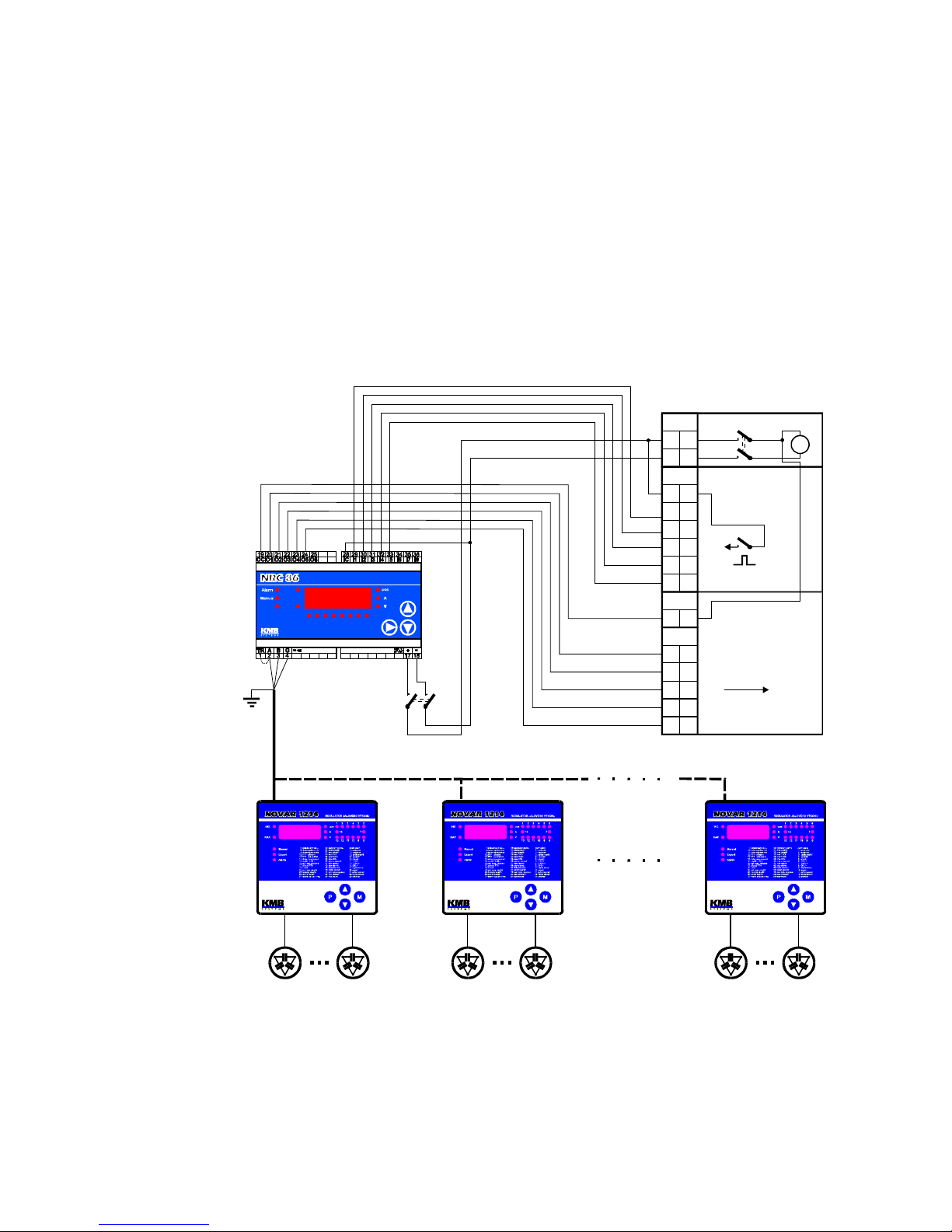
Remote Controlled Target PF Compensation System with NRC86
Remote Controller
XN
1
2
XYW
X113
+
-
9
10
11
12
13
14
2
25
+
R1
R2
R3
R4
R5
Napájení 24 VDC
Regulace
jalového
výkonu
Signalizace
regulace
jalového výkonu
S1
S2
S3
S4
S5
26
27
28
29
+
=
+
+
-
1 sec
XYH
(5x)
(5x)
Rozvaděč distributora
( AXY01, ovládací napětí 24VDC )
Remote Controller
71 2 3 4 5 6 8
20:
21: Fail state
30: Input state
Alarm state 1: Mode
2: RCC number
10: Comm. addr
11: Comm. rate
12: Comm. protocol
Rx
Tx
1A
PE
stínění
shiled
(N+1) x Novar 1xxx NRC
NRC 86-85 24VDC
Master
Slave 1
Slave N
Page 24
Novar-NRC KMB systems
24
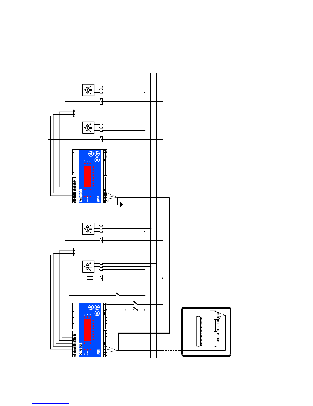
Remote Controlled Outputs Compensation System with Two
NRC86 Remote Controllers
Novar 1114 NRC
1A
NRC86-07 230VAC
L1
L2
L3
N
10A
C1 C7
Remote Controller
71 2 3 4 5 6 8
20:
21: Fail state
30: Input state
Alarm state 1: Mode
2: RCC number
10: Comm. addr
11: Comm. rate
12: Comm. protocol
Rx
Tx
C2-C6
. . . . .
PE
stínění
shiled
NRC86-07 230VAC
C8
C
1
4
Remote Controller
71 2 3 4 5 6 8
20:
21: Fail state
30: Input state
Alarm state 1: Mode
2: RCC number
10: Comm. addr
11: Comm. rate
12: Comm. protocol
Rx
Tx
C9-C13
. . . . .
RS-485
TR A B G
Page 25

Novar-NRC KMB systems
25
Combined Remote Controlled Target PF and Remote Controlled
Outputs Compensation System with NRC86 Remote Controllers,
Wireless Remote Outputs Connection
Block Diagram
XN
XYW
X113
Napáje
n
í
2
4
V
D
C
Reg
u
l
a
c
e
jalo
v
é
h
o
výk
o
n
u
Sign
a
l
i
z
a
c
e
re
g
u
l
a
c
e
jalové
h
o
v
ý
k
o
n
u
=
+
-
1
s
e
c
X
Y
H
(
5
x
)
(
5
x
)
R
o
z
v
a
d
ě
č
d
i
s
t
r
i
b
u
t
o
r
a
(
A
X
Y
0
1
)
Remote Controller
71 2 3 4 5 6 8
20:
21: Fail state
30: Input state
Alarm state 1: Mode
2: RCC number
10: Comm. addr
11: Comm. rate
12: Comm. protocol
Rx
Tx
PE
stínění
shiled
Novar 1xxx NRC
NRC 86-85 24VDCNRC86-07 230VAC
Remote Controller
71 2 3 4 5 6 8
20:
21: Fail state
30: Input state
Alarm state 1: Mode
2: RCC number
10: Comm. addr
11: Comm. rate
12: Comm. protocol
Rx
Tx
NRC86-07 230VAC
Remote Controller
71 2 3 4 5 6 8
20:
21: Fail state
30: Input state
Alarm state 1: Mode
2: RCC number
10: Comm. addr
11: Comm. rate
12: Comm. protocol
Rx
Tx
R
S
-
4
8
5
RS-485
radiomodem
Page 26

Novar-NRC KMB systems
26
6. NRC86 Remote Controller Technical Specifications
parameter NRC86 Model
NRC86-85 24VDC NRC86-07 230VAC
aux. supply voltage, power 18 ÷ 36 V DC, 4W 80 ÷ 275 V AC, 43 ÷ 67 Hz, 5 VA
100 ÷ 300 V DC, 5 W
number of output relays 5 7
output relay load rating 250 V AC / 4 A
110 V DC / 0.3 A
number of logic inputs 8 0
logic inputs parameters :
- character
- maximum voltage
- impedance
- voltage corresponding to „log. 0“
- voltage corresponding to „log. 1“
- serial number of remote controlled
PF switchover signal duration („log.
1”, RCC-mode)
galvanically isolated, polarity free
36 V DC
~ 5 kΩ
< 4 V DC
> 8 V DC
> 100 ms
communication interface
- type
- transmission rate
- protocol
- bias voltage impedance
- terminating resistor (TR)
RS-485, galvanically isolated
4.8 ÷ 19.2 kBaud
KMB / Modbus RTU
2 x 4.7 kΩ
330 Ω
working environment class C1 in compliance with IEC 654-1
operating temperature -40° ÷ +60°C
relative humidity 5 to 100 %
installation overvoltage class / level of
pollution
III-2 in compliance with EN 61010-1
EMC :
- noise suppression level
- immunity
EN 50081-2; EN 55011, class A; EN 55022, class A;
EN 61000-6-2
enclosure IP 20
dimensions 106 x 100 x 58 mm
mass max. 0.3 kg
Page 27

Novar-NRC KMB systems
27
7. MAINTENANCE, TROUBLESHOOTING
NRC86 remote controller does not require any maintenance. For reliable operation you only have to
comply with the operating conditions specified and prevent mechanical damage to the instrument.
In the event of the product’s breakdown, you have to return it to the supplier at their address.
supplier: manufacturer:
KMB systems, s.r.o.
559 Dr. M. Horákové
460 06, Liberec 7
Czech Republic
website: www.kmbsystems.eu
The product must be packed properly to prevent damage in transit. Description of the problem or its
symptoms must be sent along with the product. If warranty repair is claimed, the warranty certificate
must be sent in too. If after-warranty repair is requested, a written order must be included.
Warranty Certificate
Warranty period of 24 months from the date of purchase, however no later than within 30 months from
the dispatch date from manufacturer’s warehouse, is provided for the instrument. Problems in the
warranty period, evidently caused by poor workmanship, design or inconvenient material, will be
repaired free of charge by the manufacturer or an authorized servicing organization.
The warranty becomes void even within the warranty period if the user makes unauthorized
modifications or changes to the instrument, connects it to out-of-range quantities if the instrument is
damaged in out-of-specs impacts or from improper handling or if it has been operated in conflict with
the technical specifications.
type of product: NRC 86 ............................ serial number ..............................................
date of dispatch: ........................................... final quality inspection: ................................
manufacturer’s seal:
date of purchase: ............................................... supplier’s seal:
 Loading...