

Page 1
Lingo® SE Baseplate Installation Instructions
Description
The Lingo® SE Energy Infosystem is the next generation control processor that
functions as a system network manager and control monitor in Novar’s Logic
One® Advanced Building Control System.
Lingo SE monitors and logs the operations of the local
control modules, manages network communications,
and provides expandable and integrated control of the
building’s equipment. Lingo SE’s processing power,
compatibility, and multiple network capabilities
provide optimum control to cut energy costs, increase
comfort, and reduce equipment maintenance.
This document provides instructions for mounting and
wiring the Lingo SE baseplate and checking the
installation.
Lingo SE Specifications
Agency Approvals
Listed device: CUL/UL E90949
Standards used: UL 916, Energy Management Equipment
CSA C22.2, No. 205-M1983, Signal Equipment
Power Requirements
Voltage: 24 VAC, Class 2
Consumption: 40 VA
Input/Output Ratings
Analog Inputs: 4 to 20 mA
Digital Inputs: Contact closure only
Output (Fault): 24 VAC or VDC, 1 amp, Class 2
Operating Environment
Lingo SE with Touchscreen:
Operating temperature: 41° to 122°F (5° to 50°C)
0–80% RH, noncondensing
Storage: –4° to 158°F (–20° to 70°C)
0–90% RH, noncondensing
DOC. #569066200—C 8/17/06 1
Page 2

Lingo® SE Baseplate Installation Instructions
Lingo SE without Touchscreen
Operating temperature: 32° to 140°F (0° to 60°C)
0–80% RH, noncondensing
Storage: –40° to 158°F (–40° to 70°C)
0–90% RH, noncondensing
Physical Dimensions (Baseplate only)
Height: 19.25 inches
Width: 13.25 inches
Depth: 2.5 inches
Weight: 8 lb (All aluminum enclosure)
Precautions
Take the following precautions during installation:
Observe national and local electrical codes.
§
Connect 24 VAC power wiring to the terminals marked as 24 VAC only.
§
Connection to other terminals will damage them.
Mounting the Lingo SE
Baseplate to the Wall
Do not use the Lingo SE as a final safety device.
§
Make sure that the 24-VAC power wiring is connected to a dedicated 40 VA
§
transformer. No other devices should be powered by the transformer
connected to the Lingo SE.
Do not ground the secondary side of the transformer for this module.
§
Make sure that the Lingo SE power cannot be switched off accidentally. The
§
Lingo SE requires continuous power for proper operation.
The following items are needed to mount the Lingo SE baseplate to the wall:
The Lingo SE baseplate
§
The hex wrench (included with the baseplate)
§
Four screws (ap appropriate for mounting surface; not provided)
§
NOTE! The baseplate assembly should be mounted in an
accessible location with the top of the assembly not more
than 6 feet from the floor. The wall should have a flat and
smooth surface to prevent the baseplate from being bent.
When the baseplate is mounted to paneling or drywall,
hollow-wall anchors should be used to insure that the
assembly remains secure.
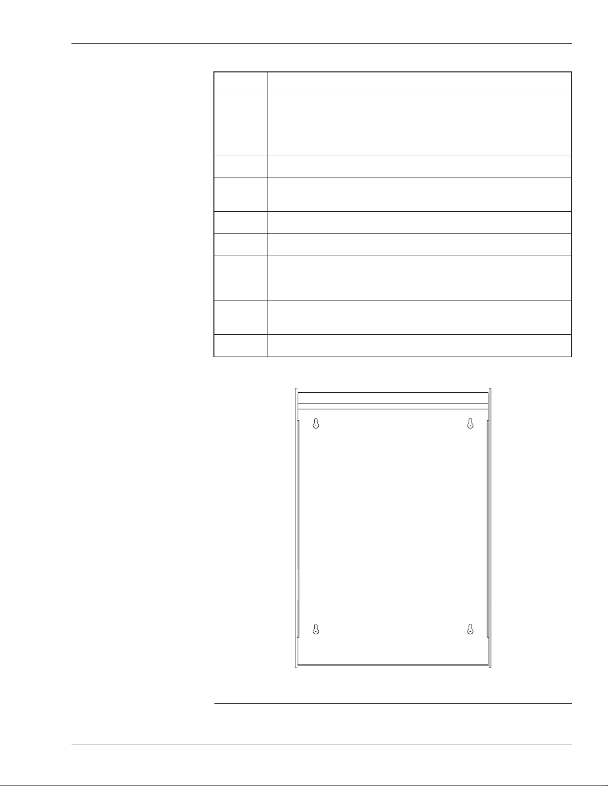
Use the following procedure and refer to Figure 1, as necessary, to mount the
Lingo SE baseplate to the wall.
2 DOC. #569066200—C 8/17/06
Page 3
Lingo® SE Baseplate Installation Instructions
Step Procedure
1 Remove the baseplate’s cover.
Use the hex wrench included with the baseplate to loosen the
§
two screws at the bottom of the baseplate.
Lift off the cover.
§
2 Position the baseplate against the wall.
3 Mark the wall to show the locations of the four slotted mounting
holes in the corners of the baseplate.
4 Drill holes in the places marked on the wall.
5 Install the hollow-wall or other appropriate fasteners.
6 Turn appropriate screws into the fasteners until approximately
one-quarter inch remains between the wall and the head of the
screws.
7 Position the baseplate over the screws and slide it down until the
screws slide into the slots.
8 Tighten the screws to secure the baseplate.
Figure 1. Lingo SE baseplate mounting holes
DOC. #569066200—C 8/17/06 3
Page 4

Lingo® SE Baseplate Installation Instructions
GND
24VAC
STATUS
FAULTLOSSTEMP PULSE
HUMIDITY
INCOM
LIGHT
AUXLAN
B MODULE C MODULE D MODULEA MODULE
1
-
4
-
2 3
+
SHLD
8
SHLD
5 6
+
SHLD
7
-
11
SHLD
9 10
-+
P1
15
+
12 13
+
SHLD
-
14 18
+
16 17
SHLD
33
+
2622
-
19 20
1
SHLD
21
2
25
+
23 24
+ -
29
+
27
- + -
28-30 31+-32
P2
P3
3634 35
1A
24V
37 38
40VA
MAX ALLOWABLE AMBIENT TEMP: 60 C (140 F)
REFER TO INSTRUCTION MANUAL FOR SETUP AND INSTALLATION.
ETHERNET
10/100
COMMUNICATION NETWORKS
R
635205000 REV 0
RS-232 PORT
EMERGENCY
PN 750110000
LINGO/2 BPL
OUTDOOR
ALL INPUTS AND OUTPUTS ARE CLASS 2.
OUTDOOR
DEMAND
SYSTEM INPUTS
PHASE
SYSTEM
POWER
PHONE LINE
LISTED ENERGY
SUBASSEMBLY
MANAGEMENT
EQUIPMENT
US
L
U
C
20M1
Ground
Terminal 36.
24-VAC, Class 2,
40 VA screw terminal.
Supplying the Lingo SE
with Power
The Lingo SE is powered by a 24-VAC, 40 VA, Class 2 transformer (not
included—the transformer kit must be purchased separately). The transformer
must be installed not more than 50 feet from the Lingo SE using minimum
18-gauge wire or mounted directly to the Lingo SE baseplate through the
knockouts on the sides of the assembly.
Refer to Figure 2, as necessary, when installing the 24 VAC, Class 2 transformer.
Step Procedure
1 Connect the blue and yellow leads from the transformer
secondary to the screw terminals labeled 24 VAC, Class 2, 40
VA, located on the Lingo SE terminal board.
2 Connect the transformer primary leads (white/black) to a
120-VAC source.
3 Connect the ground terminal (Terminal 36) to a suitable earth
ground.
4 Apply power and check voltage at the 24 VAC terminals.
Voltage should be approximately 24 to 28 VAC.
§
5 Turn off the power until needed.
Figure 2. Lingo SE baseplate wiring connections
4 DOC. #569066200—C 8/17/06
Page 5

Wiring the Lingo SE
Inputs and Outputs
Lingo® SE Baseplate Installation Instructions
NOTE! The Lingo SE requires continuous power for proper
operation. Make sure the Lingo SE power cannot be
switched off accidentally.
NOTE! The Lingo SE requires a dedicated transformer for the
electronics. A separate transformer must be provided for
its control outputs.
Refer to Figure 2, as necessary, and use the procedure provided below to wire the
Lingo SE input/output connections.
NOTE! All digital inputs should be dry contact closures.
Outdoor Light Sensor
Outdoor Temperature Sensor
Novar’s 4-mA to 20-mA Analog Light Sensor (ALS) should be connected to the
Lingo SE with two-conductor, shielded cable (Novar WIR-1010, Belden 8761, or
equivalent) wiring.
Step Procedure
1 Connect the white (+) wire from the sensor to the Lingo SE at
Terminal 25 (+) at the Outdoor Light Sensor input connections.
2 Connect the black (–) wire from the sensor to the Lingo SE at
Terminal 24 (–) at the Outdoor Light Sensor Input connections.
For outdoor temperature sensing, Lingo SE uses the 4- to 20-mA Outdoor
Temperature Sensor (OTS/2). Two-conductor, shielded cable (Novar WIR-1010,
Belden 8761, or equivalent) should be used to connect the sensor to the Lingo
SE.
Step Procedure
1 Connect the white (+) wire from the sensor to Lingo SE’s
Terminal 27 (+) at the Outdoor Temperature Sensor input
connections.
2 Connect the black (–) wire from the sensor to Lingo SE’s
Terminal 26 (–) at the Outdoor Temperature Sensor input
connections.
DOC. #569066200—C 8/17/06 5
Page 6

Lingo® SE Baseplate Installation Instructions
Outdoor Humidity Sensor
Step Procedure
1 Connect the white (+) wire from the sensor to Lingo SE’s
Terminal 23 (+) at the Humidity Sensor input connections.
2 Connect the black (–) wire from the sensor to Lingo SE’s
Terminal 22 (–) at the Humidity Sensor input connections.
Demand Pulse Input
Step Procedure
1 Connect the isolated contacts of a pulse-type utility meter or watt
transducer to Terminals 28 (–) and 29 (+), labeled Demand Pulse
Input.
Phase Loss Sensor
Step Procedure
Emergency Status Input
System Fault Output
Module Communications
1 Connect the normally open, dry contact output of an electrical
phase loss monitor to Terminals 30 (–) and 31 (+), labeled Phase
Loss Sensor Input.
Step Procedure
1 Connect the normally open, dry contact output of an emergency
monitoring system to Terminals 32 (–) and 33 (+), labeled
Emergency Status Input.
Under normal operating conditions, a normally open set of contacts will be held
closed. When an alarm occurs, the contacts open momentarily. This signal
indicates a Lingo SE fault alarm.
Lingo SE can accept connections from 128 modules in Novar’s module network
without using a Network Expander Module. (The maximum number of modules
is subject to software limitations.)
A maximum of 32 modules can be connected to each of the A, B, C, and D
Module terminals (Terminals 1–12).
NOTE! Modules with the same physical addresses must not be
connected to the same port. For example, modules with
addresses 00 and 64 have the same physical address, so they
cannot both reside on the same COM port (A, B, C, or D).
6 DOC. #569066200—C 8/17/06
Page 7

Lingo® SE Baseplate Installation Instructions
Use two-conductor, shielded cable (Novar WIR-1010, Belden 8761, or
equivalent) and the following procedure to make the module communications
connections.
Step Procedure
1 Connect the black wire from the cable to the negative (–)
terminal.
2 Connect the shield wire to the SHIELD terminal.
3 Connect the white wire to the positive (+) terminal.
NOTE! Novar’s Network Expander Module is not used with the
Lingo SE.
INCOM™
Lingo SE supports up to four demand meters and sixteen additional electrical
submeters. Sixteen meter data collectors can be configured, each with 48 data
points. Belden network cable is recommended.
Checking Installation
The following procedure should be used to connect INCOM Terminals (19–21).
Step Procedure
1 Connect the black wire from the INCOM cable to Terminal 21
(INCOM 2).
2 Connect the white wire from the INCOM cable to Terminal 20
(INCOM 1).
3 Connect the shield wire from the INCOM cable to Terminal 19
(INCOM SHLD).
Check the following items to ensure proper operation:
Make sure the baseplate is attached securely to the wall.
§
Check all wiring connections to make sure they are correct and secure.
§
If the wiring is correct and the baseplate is secure, reattach the Lingo SE
baseplate cover.
Operation of the Lingo SE requires the Lingo SE electronics. The Lingo SE
Electronics Installation Instructions (Doc. #569066100) provide information
about installing the electronics, making all other required wiring connections,
and verifying proper operation.
DOC. #569066200—C 8/17/06 7
Page 8

Lingo® SE Baseplate Installation Instructions
Model and Part Numbers
The part numbers shown in Table 1 should be used to order the necessary Novar
parts.
Table 1. Novar Part Numbers
PRODUCT MODEL NO. PART NO.
Lingo SE Baseplate Lingo/2-BPL 750110000
Lingo SE Electronics Assembly (no
—
750017000
options)
Options:
Lingo SE with Integral Touchscreen
Lingo SE with Integral Touchscreen &
Modem
Lingo SE with Modem
Lingo SE with INCOM
Lingo SE with Modem & INCOM
Lingo SE with Touchscreen & INCOM
—
—
—
—
—
—
—
750018000
750018100
750017100
750017010
750017110
750018010
750018110
Lingo SE with Touchscreen, Modem, &
INCOM
24-VAC, 40 VA, Class 2 Transformer Kit 24V-XFR 730090000
Analog Light Sensor ALS-300 708100000
Outdoor Temperature Sensor OTS/2 735070000
Two-conductor, shielded cable (Belden
WIR-1010 709001000
8761 equivalent)
Ethernet® Direct-Connect Crossover Cable — 770077000
Logic One® and Lingo® are registered trademarks of Novar.
INCOM™ is a trademark of Eaton Cutler-Hammer.
Ethernet® is a registered trademark of Xerox Corporation.
The material in this manual is for information purposes only. The contents and the product it describes
are subject to change without notice. Novar makes no representations or warranties with respect to this manual.
In no event shall Novar be liable for technical or editorial omissions or mistakes in this manual, nor shall it be liable
for any damages, direct or incidental, arising out of or related to the use of this manual. No part of this manual
may be reproduced in any form or by any means without prior written permission from Novar.
Copyright © 2006 by Novar. All Rights Reserved. Printed in the U.S.A.
Novar; 6060 Rockside Woods Blvd., Cleveland, OH 44131
8 DOC. #569066200—C 8/17/06
Tel.: 800.348.1235 www.novar.com
 Loading...