

Novar ETM-2040 Installation Instructions Manual
ETM-2040 Installation
Instructions
DOC. #560075000 2/12/01 PRINTED IN U.S.A.

FCC Information
This device complies with Part 15 of the FCC rules. Operation is subject to the following
two conditions: (1) This device may not cause harmful interference, and (2) this device
must accept any interference received, including interference that may cause undesired
operation.
Industry Canada
NOTE! This equipment has been tested and found to comply with the limits for
a Class B digital device pursuant to Part 15 of the FCC Rules. These
limits are designed to provide reasonable protection against harmful
interference when the equipment is operated in a commercial
environment. This equipment generates, uses, and can radiate radio
frequency energy and, if not installed and used in accordance with the
instruction manual, may cause harmful interference to radio
communications. Operation of this equipment in a residential area is
likely to cause harmful interference, in which case the user will be
required to correct the interference at his own expense.
CAUTION! Any changes or modifications not expressly approved by Novar
Controls Corporation could void your authority to operate this
equipment.
This digital apparatus does not exceed the Class B limits for radio noise emissions from
digital apparatus set out in the interference-causing equipment standard entitled Digital
Apparatus , ICES-003, of Industry Canada.
Cet appareil numérique respecte les limites de bruits radioélectriques applicables aux
appareils numériques de Classe B préscrites dans la norme sur le matériel brouiller:
Appareils Numériques , NMB-003, édictée par l’Industrie Canada.
Disclaimer
LOGIC ONE ® is a registered trademark of Novar Controls Corporation.
The material in this manual is for information purposes only. The contents and the
product it describes are subject to change without notice. Novar Controls Corporation
makes no representations or warranties with respect to this manual.
In no event shall Novar Controls Corporation be liable for technical or editorial omissions
or mistakes in this manual, nor shall it be liable for any damages, direct or incidental,
arising out of or related to the use of this manual.
Copyright © 2001 by Novar Controls Corporation. All rights reserved.
No part of this manual may be reproduced in any form or by any means
without prior written permission from Novar Controls Corporation.
Novar Controls Corporation
3333 Copley Road, Copley, OH 44321
Tel: (330) 670-1010 www.novarcontrols.com

De scrip tion
ETM- 2040 Speci fi ca tions
ETM-2040 Installation Instructions
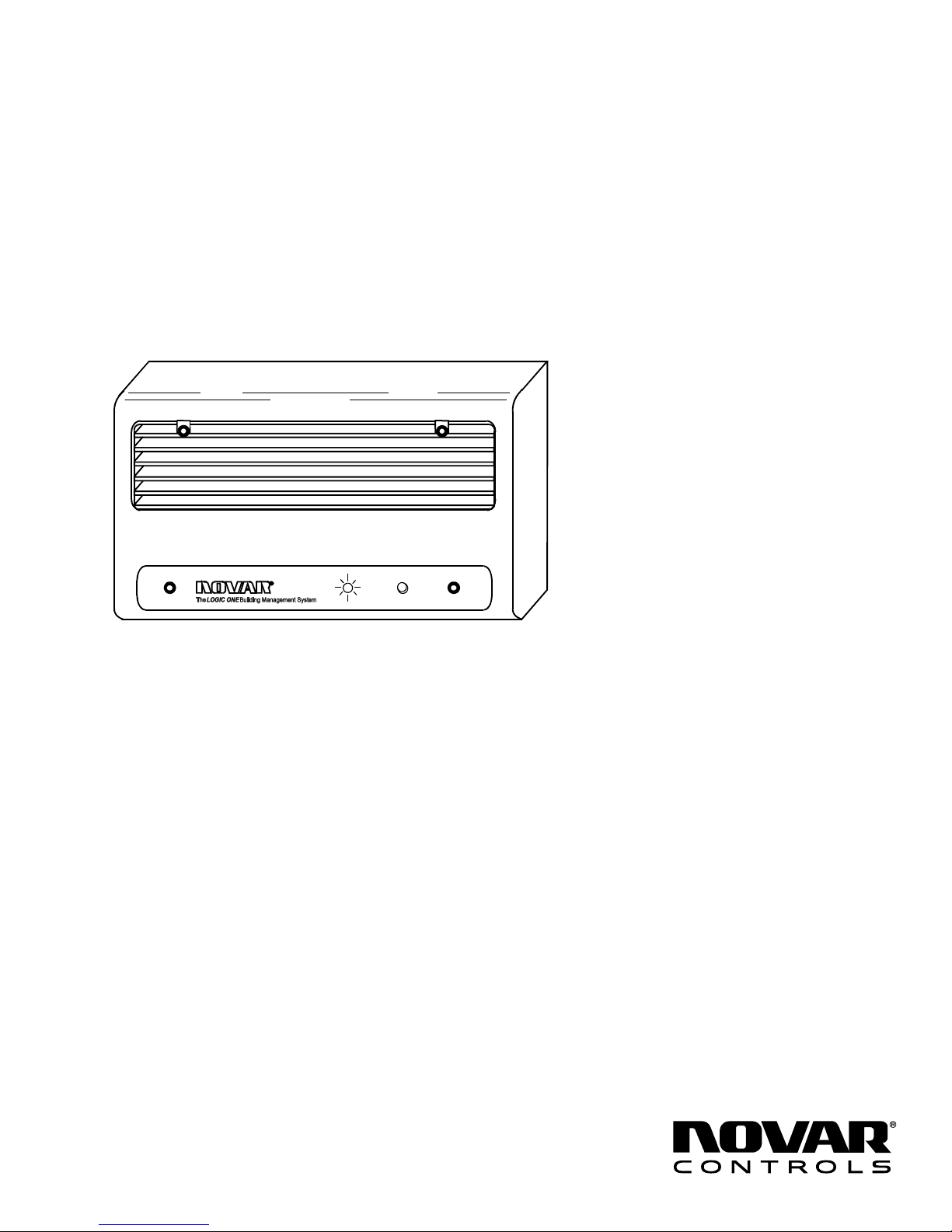
The Elec tronic Ther mo stat Mod ules (ETMs) are LOGIC ONE® in tel li gent con trol
mod ules that can be dis trib uted through out a build ing to pro vide lo cal di rect digi tal
con trol of uni tary, pack aged, staged HVAC sys tems. The ETM- 2040 is a wall- mount
mod ule that must be mounted in the space be ing con trolled be cause the sen sor is
con nected di rectly to the mod ule. One ad di tional re mote tem pera ture sen sor and a
digi tal dirty fil ter switch can be wired to the ETM- 2040.
This document provides in struc tions for mount ing the ETM base plate, wir ing the
module, set ting the ad dress, in stall ing the elec tron ics, and check ing the
in stal la tion.
Power Re quire ments
Volt age: 24 VDC, Class 2
Cur rent: 120 mA
Op er at ing En vi ron ment
Tem pera ture: 32° to 122°F (0° to 50°C)
Hu mid ity: 0 to 95% Rela tive, non con dens ing
Pre cau tions
Mount ing the ETM- 2040
Base plate
Physi cal Di men sions
Height: 4.875 inches
Width: 7.093 inches
Depth: 1.75 inches
Weight: 1 lb
Take the fol low ing pre cau tions dur ing in stal la tion:
Ob serve na tional and lo cal elec tri cal codes.
§
Ob serve volt age and cur rent lim its marked on the mod ule.
§
Do not ex ceed 24-VAC at 1 am pere on any load.
§
The ETM- 2040 base plate should be mounted hori zon tally, ap proxi mately 5 feet
above the floor, in an area that is free from drafts and sud den changes in
tem pera ture. The base plate may be mounted to an elec tri cal junc tion box or
di rectly to a wall or panel.
The baseplate is shipped with a hardware kit that contains four screws, four
hollow- wall an chors, one mod ule ad dress la bel, and 15 wire nuts.
DOC. #560075000 2/12/01 1
NOTE! Use the hollow- wall an chors when mount ing to pan el ing
or dry wall. When mount ing to a ce ment block or brick
wall, use a 3/8-inch to ½-inch layer of in su la tion be tween
the wall and the base plate.
 Loading...