

Novar NRC86, 1xxx NRC Operating Manual
KMB systems, s.r.o.
Dr. M. Horákové 559, 460 06 Liberec 7, Czech Republic
tel. +420 485 130 314, fax +420 482 736 896
email : kmb@kmb.cz, internet : www.kmb.cz
10/2013
Remote Controlled Target PF and Remote Controlled
Outputs Compensation Systems Based on Novar Line
Power Factor Controllers
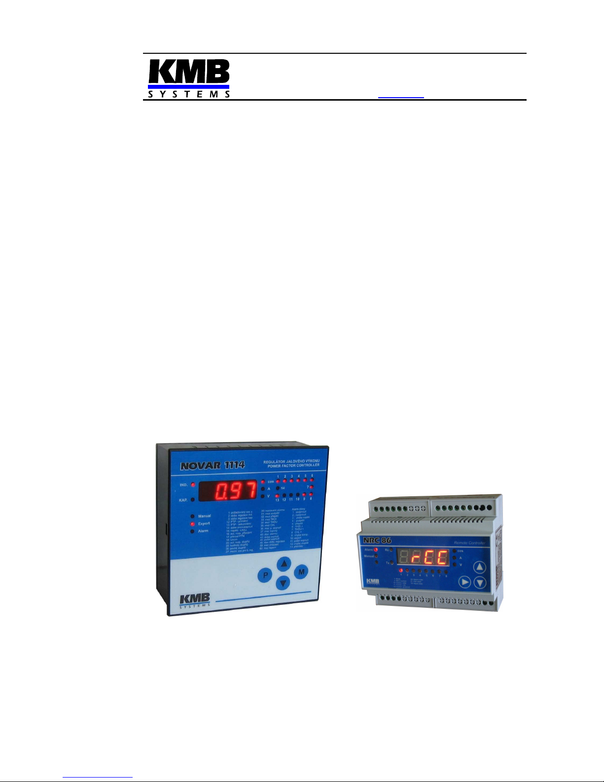
NOVAR-1xxx NRC Power Factor Controller
NRC 86 Remote Controller
Firmware v. 1.8 ( Novar ) / 1.0 ( NRC86 )
Operating Manual

Novar-NRC KMB systems
2
LIST OF CONTENTS
1. APPLICATION..................................................................4
1.1 Remote Controlled Target Power Factor Compensation Systems ..................................................4
1.2 Remote Controlled Outputs Compensation Systems .......................................................................4
1.3 History of Firmware Versions ..............................................................................................................4
1.4 Manual Structure...................................................................................................................................4
2. THE „NOVAR1XXX NRC“ SPECIAL VERSION POWER
FACTOR CONTROLLERS......................................................6
2.1 Operation ...............................................................................................................................................6
2.1.1 Remote Controlled Power Factor (Cosinus) Mode – the „RCC“ Mode...........................................6
2.1.2 Remote Controlled Outputs – the „I/O“ Mode.................................................................................8
2.2 Parameters 01(07) – Target PF for Metering Rate 1(2) / Actual Remote Controlled Target PF......8
2.2.1 Parameter 01..................................................................................................................................8
2.2.2 Parameter 07..................................................................................................................................8
2.3 Parameters 30 – Alarm Setting, 40 – Alarm Status ............................................................................9
2.3.1 Alarm No. 6 – Undercurrent Alarm with Adjustable Limit or Alarm by Import with Adjustable Limit
and Fixed Outputs Release at Export..............................................................................................................9
2.3.1.1 Undercurrent Alarm with Adjustable Limit..................................................................................9
2.3.1.2 Alarm by Import with Adjustable Limit and Fixed Outputs Release at Export ............................9
2.3.2 Alarm No. 15 – Remote Control Failure .......................................................................................10
2.4 Parameters 50, 51, 52 – Instrument Address, Communication Rate and Communication
Protocol / NRC86 response timeout ...............................................................................................................11
2.5 Parameter 53 – Remote Control Mode ..............................................................................................11
2.6 Parameters 80,81 – Remote Controlled Target PFs and Remote Controlled PF Serial Number .13
3. NRC 86 REMOTE CONTROLLER................................. 14
3.1 Description ..........................................................................................................................................14
3.2 Operation .............................................................................................................................................15
3.2.1 Remote Controlled Power Factor (Cosinus) Mode – the „RCC“ Mode.........................................15
3.2.2 Remote Controlled Outputs – the „I/O“ Mode...............................................................................15
3.2.3 Manual Mode................................................................................................................................15
3.3 NRC86 Remote Controller Parameters .............................................................................................15
3.3.1 Parameter 01 – Remote Control Mode ........................................................................................15
3.3.2 Parameter 02 – Remote Controlled PF Serial Number ................................................................16
3.3.3 Parameter 05 – Number of Processed Outputs (in I/O mode) .....................................................17
3.3.4 Parameter 06 – Daisy-Chain Communication Mode („Cascade“) ................................................17
3.3.5 Parameters 10, 11, 22 – Instrument Address, Communication Rate and Communication Protocol17

Novar-NRC KMB systems
3
3.3.6 Parameter 20 – Alarm Status.......................................................................................................17
3.3.7 Parameter 21 – Instrument Failure Status ...................................................................................17
3.3.8 Parameter 30 – Logic Inputs Status.............................................................................................18
3.4 Installation ...........................................................................................................................................18
3.4.1 Power Supply ...............................................................................................................................18
3.4.1.1 24 VDC Power Supply Version................................................................................................18
3.4.1.2 230 VAC Power Supply Version ..............................................................................................18
3.4.1.3 Protection.................................................................................................................................18
3.4.2 Logic Outputs ...............................................................................................................................18
3.4.3 Logic Inputs..................................................................................................................................19
3.4.4 Communication Interface .............................................................................................................19
4. PUTTING IN OPERATION..............................................20
4.1 Remote Controlled Target PF Compensation Systems ..................................................................20
4.2 Remote Controlled Outputs Compensation Systems .....................................................................21
5. CONNECTION EXAMPLES............................................23
6. NRC86 REMOTE CONTROLLER TECHNICAL
SPECIFICATIONS..................................................................26
7. MAINTENANCE, TROUBLESHOOTING .......................27

Novar-NRC KMB systems
4
1. Application
1.1 Remote Controlled Target Power Factor Compensation Systems
When connecting major sources to medium voltage network, a remote control of reactive power is
often required. One possibility is to control target power factor using pulse signals from distributor (eg,
transmitted via a GPRS modem). Such equipped compensation systems can be implemented using
the Novar1xxx NRC power factor controller and the NRC86 remote controller.
1.2 Remote Controlled Outputs Compensation Systems
Alternatively, the NRC86 controller in combination with the Novar1xxx NRC power factor controller can
be used for remote controlled outputs compensation systems.
In practice, there may be cases where compensation capacitors must be placed at great distance from
the measuring current transformer (CT). Since the maximum length of the wires to the CT is limited
due to the limited maximum loop impedance, in some cases the power factor controller cannot be
installed in a switchboard with capacitors but at the measurement point near the CT. In such cases, it
is necessary to install a multi-core power cable connecting the controller with capacitor contactors. If,
for technical or other reasons, this solution is impossible and there exists a suitable communication
channel (cable or other media) between the points, the NRC86 remote controller can be used for
driving the capacitor contactors.
1.3 History of Firmware Versions
Novar 1xxx NRC
version date of release note
1.3 10/2010 - basic version
1.4 8/2011 - THDI alarm replaced with adjustable current limit undercurrent
alarm ( parameters 30, 40)
1.5 11/2011 - RCC/IO communication error fixed
1.6 09/2012 - combined RCC and I/O operation and multiple NRC86 units
performance support added
1.7 04/2013 - “Alarm by import with adjustable limit and fixed outputs release at
export" function added
1.8 10/2013 - PF display error at undercurrent alarm activation correction
NRC 86
version date of release note
0.1 10/2010 - basic version
0.2 01/2011 - „I/O“-mode for two NRC86 units added
0.3 04/2011 - general I/O device feature added
1.0 09/2012 - combined RCC and I/O operation and multiple NRC86 units
performance support added
1.4 Manual Structure
This Operating Manual describes the NRC86 remote controller and the Novar1xxx NRC controller’s
specific features only. At least basic knowledge of Novar line power factor controllers is necessary for
understanding it.

Novar-NRC KMB systems
5
Detailed description of the Novar power factor controllers can be found on the manufacturers website
at www.kmbsystems.eu .

Novar-NRC KMB systems
6
2. The „Novar1xxx NRC“ Special Version Power Factor
Controllers
The „NRC“ special version is available for following Novar power factor controller (PFC) models :
1106, 1114, 1206, 1214 ( marking example : Novar1214 NRC). The 1414 and 1312 models can be
delivered with limited functionality only – see below.
The PFCs are equipped with a RS-485 communication interface and with the special version firmware
„0E“ that allow, in combination with the NRC86 remote controller, either a remote controlled power
factor operation mode or a remote controller outputs operation mode .
From point of view of hardware and installation, the „NRC“-version PFCs don’t differ from standard
PFC models (with exception of models Novar1414 NRC and Novar1312 NRC, see below) and detailed
description can be found at the standard Novar1xxx operation manual. The only difference is their
firmware – they are equipped with special version firmware „0E“. The PFCs are marked with the „0E“
code :
• on the panel of the controller at initial phase after supply voltage is applied. When the
firmware version is displayed the first two characters of displayed string „0E1.3“ stands for
special firmware version 0E, and the last two stands for basic firmware version 1.3.
• at firmware window of the product label on the rear panel of the controller. For example
marking „1.3/OE“ means basic firmware version 1.3 and the character after a slash mean
special version „0E“
The only limitation of this firmware version is that the Modbus communication protocol is not
supported. All of other features are the same as the standard version.
The Novar1414 NRC and the Novar 1312 NRC models differ, moreover, from the standard models by
not allowing automatic connection detection and automatic sections’ powers recognition. Therefore,
the type of connection (parameter No. 16) and individual sections’ power sizes (parameter No. 25)
must be entered manually.
2.1 Operation
2.1.1 Remote Controlled Power Factor (Cosinus) Mode – the „RCC“ Mode
The Novar1xxx NRC PFC (or several PFCs) is connected to the NRC86 remote controller through a
RS-485 communication link. Using additional parameters of the „0E“ special firmware the PFC can be
set up to the RCC-mode (Remote Controlled Cosϕ). After being set, the PFC periodically reads serial
number of remote controlled PF value in range 1 ÷ 5 from the NRC86 unit.
In the PFC it is possible to preset five PF values corresponding to the remote controlled PF serial
numbers. Default values are –0.95 / -0.97 / 1.00 / 0.97 / 0.95 , but they can be freely changed.
According this setting the PFC keeps preset target PF value that is dynamically controlled by the
remote controlled PF serial number from the NRC86 unit ( standard target PF value in parameter 01
has no meaning in this mode).
Simultaneously, other NRC86 units (up to six, i.e. seven units in total) in function of remote controlled
outputs (see below) can be connected to the communication link too.

Novar-NRC KMB systems
7
Tab. 2.1 : Novar-1xxx NRC Additional and Affected Parameters
#
name range step default comment
1
(7)
target PF for
metering rate 1
(2)
actual remote
controlled
target PF
0.80 L ÷ 0.80 C
„EX.XX“ format indicates
remote controlled target PF
value in the „RCC“-mode
0.01 0.98 L
in the „RCC“-mode (see par. 53), depending
on the metering rate 2 parameter setting and
state, the actual value of target PF is defined
by setting of the „remote controlled target
PF“ (par. 80) and by actual state of the
„remote controlled PF serial number“ (par.
81)
6 metering rate 2
enable/disable
0 – 1 – E — 0
when the metering rate 2 parameter enabled
(value "1" or "E") and the "RCC"-mode (par.
53) enabled, PF control is carried out by the
„remote controlled target PF“ when the
metering rate 2 just active only (i. e. when
digital input activated or active power export
occurs ); for metering rate 1, the PF is
controlled by the target PF for metering rate
1 (par. 01), regardless to the „remote
controlled target PF“ value
30 alarm setting
0 / indication only / actuation
only / indication and actuation
— indication and
actuation
from
undercurrent,
voltage signal
absence or
section error
1... undercurrent
…
14 … external alarm
15 ... NRC86 connection loss
Alarm No. 15 is activated when no response
from the NRC86 unit occurs during approx. 20
seconds. The alarm actuation function is
intended mainly for the „I/O“-mode.
40 alarm
instantaneous
condition
„0“ indicates passive state, „1“ indicates active
state. Alarm numbering according par. 30.
50
instrument
address
1 ÷ 255 1 1
In the„RCC“- and a the„I/O“-mode the preset
value has no meaning. The fixed address 200
is used for communication with the NRC86
unit.
51
communication
rate
4800 – 9600 – 19200 Bd — 9600
In the„RCC“- and a the„I/O“-mode the value
must correspond to that of the NRC86 unit
52 communication
protocol
NRC86
response
timeout
KMB(P0)
0 – 1 – 2 – 3 – 8 sec
- KMB(P0)
0 sec
Modbus-RTU protocol cannot be set.
In the„RCC“- and a the„I/O“-mode (par. 53)
the parameter defines the NRC86 unit
response timeout in seconds.
53 remote control
mode
-(=off) / IO / IO. / RCC / RCC.
/ RCCP
- -(=off)
- … remote control mode switched off comm. interface available for standard
remote monitoring (protocol KMB only)
- IO … „I/O“-mode only (with up to 7 NRC86s)
- IO. … „I/O“-mode with actual PFC state
broadcast
- RCC … „RCC“-mode with optional
simultaneous „I/O“-mode (with up to 6
additional NRC86s)
- RCC. … „RCC“-mode with actual PFC state
broadcast
- RCCP … „RCCP“-mode (passive)
80 remote
controlled
target PF No. 1
÷ 5 ( in
„RCC“-mode )
0.80 L ÷ 0.80 C
0.01 1. = 0.95 C
2. = 0.97 C
3. = 1.00
4. = 0.97 L
5. = 0.95 L
individual remote controlled target PF values
EC1÷÷÷÷EC5 corresponding to remote
controlled PF serial number (par. 81) can be
set in a side branch
81 remote
controlled PF
serial number
( in „RCC“mode )
1 ÷ 5
1 3
the value is periodically read from the NRC86
unit
- slowly flashing dec. point indicates off-line
state; the value displayed corresponds to the
last read value
- slowly flashing dec. point indicates default
state 3 ( at long time off-line state )

Novar-NRC KMB systems
8
2.1.2 Remote Controlled Outputs – the „I/O“ Mode
The Novar1xxx NRC PFC is connected to the NRC86 remote controller (optionally to more of such
controllers) through a RS-485 communication link. Capacitor (or choke) contactors are not connected
to the PFC outputs but to corresponding outputs of the NRC86 controller(s).
Using additional parameters of the „0E“ special firmware the PFC can be set up to the I/O-mode
(Input/Output). Then the PFC output state is periodically transmitted to the NRC86 controller(s) and its
outputs state „copies“ the PFC outputs state. The outputs refresh speed is between 3 ÷ 10 times per
second if a transparent communication medium ( i.e. a medium with no transmission delay) is used (it
depends on preset communication rate and remote control mode). If usual metallic cable is used
maximum distance between the PFC and the NRC86 unit is up to 1 km, but it can be nearly unlimited
for suitable wireless media.
Up to seven NRC86 units can be connected. At each of the units you can set how many outputs to
process (i.e. how many of its outputs are controlled by the PFC outputs); then other outputs of the
PFC are processed by other NRC86 units. By this you can control outputs which are spatially spread
within reach of the communication line.
Desired remote controlled mode ( either the „RCC“ or the „I/O“ ) can be set using additional
parameters according Tab. 2.1°. Essential matters that differ from standard version are bolded.
Significant parameters detailed description follows.
2.2 Parameters 01(07) – Target PF for Metering Rate 1(2) / Actual Remote
Controlled Target PF
2.2.1 Parameter 01
If the remote control mode (par. 53) is switched off or if the metering rate 2 control (par. 06) is
enabled, parameter 01 has usual meaning, i.e. preset target PF value ( for metering rate 1).
If any of RCC-modes is set and the metering rate 2 control is disabled simultaneously, the target
PF is remote controlled by external NRC86 unit. In such case an actual value of remote controlled PF
with preceding „E“ character is displayed in parameter 01 ( for example E0
E0E0
E0.97
9797
97 ). This value cannot
be edited in parameter 01; it is defined by preset value of remote controlled target PF in parameter 80,
corresponding to actual state of remote controlled PF serial number. This serial number ( in range 1 ÷
5 ) is periodically read from theNRC86 unit and its value can be checked in parameter 81.
Thus the PFC controls PF to one of preset values in parameter 80. Usual value of parameter 01, i.e.
standard target PF value for metering rate 1, has no meaning in the RCC-mode and it is not displayed.
But, if the metering rate 2 control (par. 06) is enabled, the parameter 01 has usual meaning - preset
target PF value ( for metering rate 1). Then, if the metering rate 2 is inactive actually, the parameter 01
target PF is used for PF control and the remote controlled target PF value is ignored.
2.2.2 Parameter 07
The standard meaning of this parameter is target PF for metering rate 2 (the second tariff). If the
metering rate control (parameter 06) is disabled its value has no meaning.
If the metering rate 2 control is enabled and the RCC-mode is off, target PF is defined by the
parameter 01 or 07 according actual state of the metering rate 2 control value.

Novar-NRC KMB systems
9
If the metering rate 2 control is enabled and any of the RCC-modes is set simultaneously, the
target PF is remote controlled by external NRC86 unit only when the metering rate 2 (tariff 2) just
active. In such case, the actual value of remote controlled PF with preceding „E“ character is
displayed in parameter 07 ( in the same way as in the parameter 01 when the metering rate 2 control
disabled). The parameter 01 has in such case its usual meaning, i.e. preset target PF value for tariff 1.
Thus, if the tariff 2 just inactive, the PF is controlled by the parameter 01 value and the remote
controlled target PF value is ignored.
The tariff2 value is evaluated in the usual way: either by state dig. input (1) or export (E).
2.3 Parameters 30 – Alarm Setting, 40 – Alarm Status
2.3.1 Alarm No. 6 – Undercurrent Alarm with Adjustable Limit or Alarm by Import with
Adjustable Limit and Fixed Outputs Release at Export
At standard Novar 1xxx controllers, the alarm No. 6 is controlled by THDI value.
At the Novar 1xxx NRC controllers, the alarm is not evaluated. The alarm No. 6 has one of following
meanings depending on its setting :
2.3.1.1 Undercurrent Alarm with Adjustable Limit
This is in fact enhanced undercurrent alarm. Behaviour of the alarm corresponds to the alarm No. 1
(thus, it is controlled by Ieff value); furthermore, the undercurrent limit value in “per mille”(ppt, range 0
÷ 200 ppt) of nominal current (5A/1A according parameter 13 setting) can be set in parameter 33.
For this alarm behaviour, the alarm No. 1 must be set in the same way as the alarm No. 6.
The limit value setup example : CT ratio (par. 12,13 ) is set to 500/5A. We intend to set the
undercurrent limit to 15A. Nominal current corresponds to the CT primary value, i.e. 500A, one ppt of
this is 0.5A. So we set the parametr 33 to 15 / 0.5 = 30.
2.3.1.2 Alarm by Import with Adjustable Limit and Fixed Outputs Release at Export
For this alarm functionality, the actuation function of the alarm No. 1 must be (unlike the function
described above) switched off (usual value 0
00
0) and the actuation function of the alarm No. 6 must be
switched on (usual value 2
22
2), simultaneously. Then :
• The alarm No. 6 is triggered as soon as fifteen-minute average value of the active current
Iact is either positive (=import), or it is negative, but its absolute value is below the preset limit
in “per mille”(ppt, range 0 ÷ 200 ppt) of nominal current (5A/1A according parameter 13
setting) in parameter 33. During the check a hysteresis of +/-1mA is applied.
• When the actuation is triggered all of the fixed sections are set to their preset states. The
controller goes on operation with the remaining ones. If all of the sections are fixed the power
factor control is suppressed.
• As soon as the fifteen-minute average value of the active current Iact gets negative (=export)
and its absolute value exceeds the preset limit in the parameter 33, the alarm gets inactive.
At the same time, all of the sections preset as fixed ones are released for the control process,
i.e. they are considered as standard control sections.
• This alarm function setting is indicated by slowly flashing decimal points at the sections
pressed as fixed at the parameter 26, that denotes their conditional behaviour
 Loading...