

Page 1
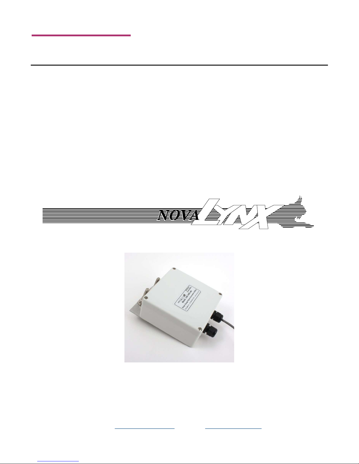
255-100C-4
User Manual
255-100C-4
255-100C-4N
4-20 mA Current Loop Signal Converter
For use with the 255-100 Analog Output Evaporation Gauge
And the 255-200 Evaporation Pan (each sold separately)
255-100C-4N
Phone (530) 823-7185 USA Toll Free (800) 321-3577 Fax (530) 823-8997
Email [email protected] Website www.novalynx.com
Page 2

NovaLynx Corporation
Receiving and Unpacking
Carefully unpack all components and compare to the packing list. Notify NovaLynx Corporation
immediately concerning any discrepancy. Inspect equipment to detect any damage that may have
occurred during shipment. In the event of damage, any claim for loss must be filed immediately with
the carrier by the consignee. Damages to equipment sent via Parcel Post or UPS require the consignee
to contact NovaLynx Corporation for instructions.
Returns
If equipment is to be returned to the factory for any reason, call NovaLynx between 8:00 a.m. and 4:00
p.m. Pacific Time to request a Return Authorization Number (RA#). Include with the returned
equipment a description of the problem and the name, address, and daytime phone number of the
sender. Carefully pack the equipment to prevent damage or additional damage during the return
shipment. Call NovaLynx for packing instructions in the case of delicate or sensitive items. If packing
facilities are not available take the equipment to the nearest Post Office, UPS, or other freight service
and obtain assistance with the packaging. Please write the RA# on the outside of the box.
Warranty
NovaLynx Corporation warrants that its products are free from defects in material and workmanship
under normal use and service for a period of one year from the date of shipment from the factory.
NovaLynx Corporation's obligations under this warranty are limited to, at NovaLynx's option: (i)
replacing; or (ii) repairing; any product determined to be defective. In no case shall NovaLynx
Corporation's liability exceed product's original purchase price. This warranty does not apply to any
equipment that has been repaired or altered, except by NovaLynx Corporation, or that has been
subjected to misuse, negligence, or accident. It is expressly agreed that this warranty will be in lieu of
all warranties of fitness and in lieu of the warranty of merchantability.
Address
NovaLynx Corporation
431 Crown Point Circle, Suite 120
Grass Valley, CA 95945-9531 USA
Phone: (530) 823-7185
Fax: (530) 823-8997
Email: [email protected]
Website: www.novalynx.com
Copyright © 1988-2018 by NovaLynx Corporation
200-100C-4 Page 2 September 2018
Page 3

NovaLynx Corporation
CONTENTS
1 FORWARD ....................................................................................................................................................................... 4
2 INTRODUCTION ............................................................................................................................................................... 4
3 TECHNICAL SPECIFICATION ............................................................................................................................................. 4
4 INSTALLATION ................................................................................................................................................................. 5
5 WIRING DIAGRAM ........................................................................................................................................................... 7
6 CALIBRATION ................................................................................................................................................................... 7
7 SINGLE-POINT OFFSET ADJUSTMENT ............................................................................................................................. 8
8 MAINTENANCE ................................................................................................................................................................ 8
APPENDIX A ............................................................................................................................................................................. 9
200-100C-4 Page 3 September 2018
Page 4
NovaLynx Corporation
1 FORWARD
Thank you for purchasing NovaLynx products. NovaLynx has been designing and manufacturing
weather instruments since 1988. NovaLynx represents several well-known brands of quality
manufacturers, including Gill Instruments, RM Young, Kipp & Zonen, and Vaisala. It is our hope that our
products will meet all your monitoring requirements.
2 INTRODUCTION
The 255-100C-4 Signal Conditioner's output is a 4-20 mA signal proportional to the resistance of a
rotary potentiometer. It is designed to work with the 255-100 Analog Output Evaporation Gauge and
the 255-200 Evaporation Pan (sold separately). These three components combine to provide a means
to gauge evaporation in systems that require 4-20 mA loop-driven signals.
The Signal Conditioner can be purchased as a bare board (Part# 255-100C-4) or enclosed in a weathertight (IP65) enclosure (Part# 255-100C-4N). Connections to the circuit board are via screw terminals.
The enclosure has two cable grip fittings for cable entry and a bracket for mounting to a mast up to
1 ⅜" (35 mm) in diameter. Cable is not supplied.
3 TECHNICAL SPECIFICATION
The 255-100 Analog Output Evaporation Gauge contains a precision 1-turn potentiometer coupled to a
gear which rotates as water level in the evaporation pan slowly decreases. One complete revolution of
the gear represents 10 inches of vertical movement of the float inside the Evaporation Gauge. As a
practical matter, due to the way the plumbing is arranged, the effective measurement range is from
9.4" to a minimum of 2.5" (239 mm to 64 mm).
Stripe
Angle
(approx)
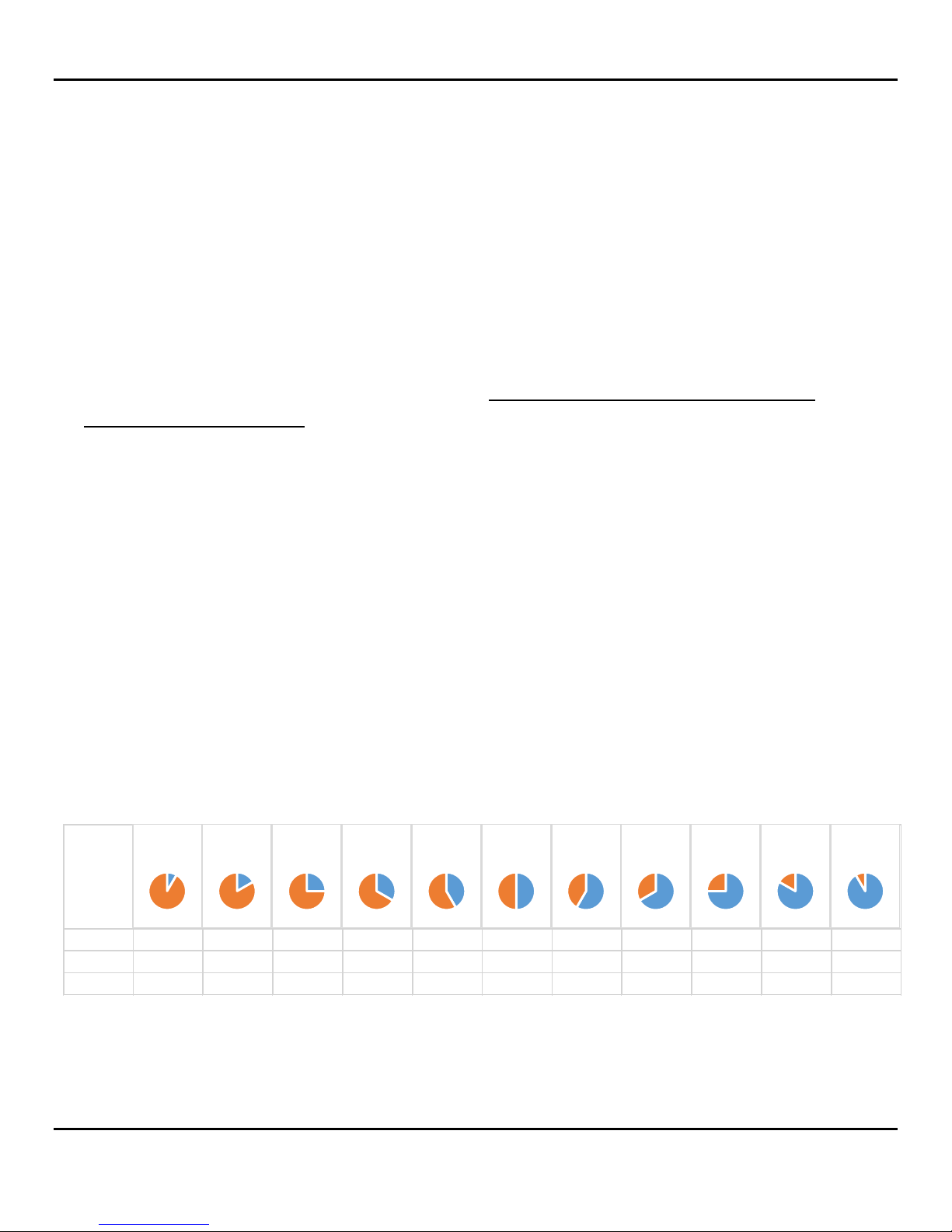
Inches 9.2 8.3 7.5 6.7 5.8 5.0 4.2 3.3 2.5 1.7 0.8
mm 233 212 191 169 148 127 106 85 64 42 21
mA 18.7 17.3 16.0 14.7 13.3 12.0 10.7 9.3 8.0 6.7 5.3
30 60 90 120 150 180 210 240 270 300 330
Signal Output at Various Angles
200-100C-4 Page 4 September 2018
Page 5
NovaLynx Corporation
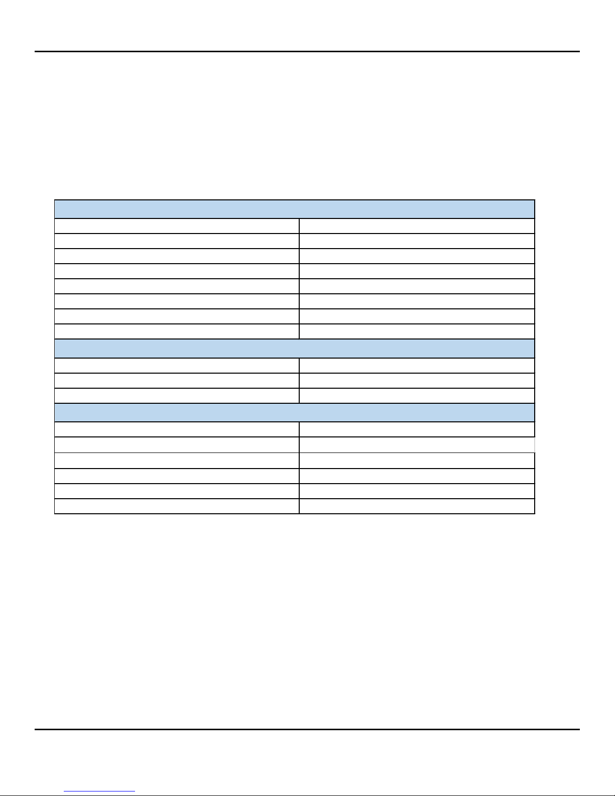
Potentiometer Specification
Transmitter Specification
Overall Specification
The potentiometer has an electrical "dead band" which is marked by a white stripe on the gear. The "dead
band" occupies 20 degrees of rotation, so to compensate the sensor is calibrated from 4.0 mA to 19.1 mA.
The formula is ((340/360 *16)+4) = 19.1 mA.
The potentiometer has high accuracy and linearity, but the overall resistance varies from one
potentiometer to another (± 10%). For this reason each Signal Conditioner is calibrated with the
companion Analog Output Evaporation Gauge.
Accuracy 0.25%
Linearity 0.25%
Rotation 360° continuous
Electrical angle 340° ± 1°
Resistance 1,000 ohms ± 10%
Operating temperature -40° to +140° F (-40° to +60°C)
Mechanical range 0 to 10 inches (0-254 mm)
Electrical range 0 to 9.444 inches (0-239.9 mm)
Output span (340 degrees) 4 to 19.1 mA = 0 to 9.444 inches (0 to 239.9 mm)
Supply voltage 8 to 30 Vdc
Connection type 2-wire current loop
Cable Not included
Cord grip diameter range (255-100C-4N only)
Mounting (255-100C-4N only)
200-100C-4 Dimensions (circuit board) 3.0 x 2.0 x 1.6 inches (7.6 x 5.1 x 4.1 cm)
200-100C-4N Dimensions (NEMA box) 4.8 x 4.7 x 2.2 inches (12.2 x 12.0 x 5.6 cm)
Weight / Shipping 1 lbs (0.45 kg) / 2 lbs (0.91 kg)
0.181" to 0.312" (4.6 to 7.9 mm) diameter
1 ⅜" (35 mm) diameter pipe mount
4 INSTALLATION
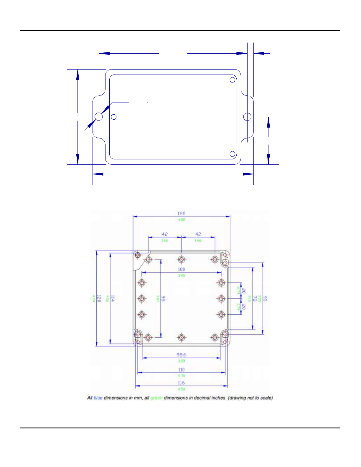
The 200-100C-4 Signal Conditioner circuit board must be housed in a weatherproof enclosure. The
circuit board is mounted to a small plate which has two mounting holes for easy attachment to a flat
surface (Figure 1). One of the mounting holes also secures a terminal strip above the circuit board.
The 200-100C-4N includes a weatherproof enclosure and hardware for mounting to a mast up to 1 ¼"
(3.2 cm) in diameter. The mast mounting hardware can be removed and the enclosure mounted to a
flat surface instead if required. There are four mounting holes, accessible when the lid of the enclosure
is removed (Figure 2). Mount the enclosure with the cable grips at the bottom.
200-100C-4 Page 5 September 2018
Page 6
NovaLynx Corporation
2.250"
3.500" 0.150"
ø 0.185"
1.125"
3.800"
Figure 1
200-100C-4 Page 6 September 2018
Figure 2
Page 7
NovaLynx Corporation
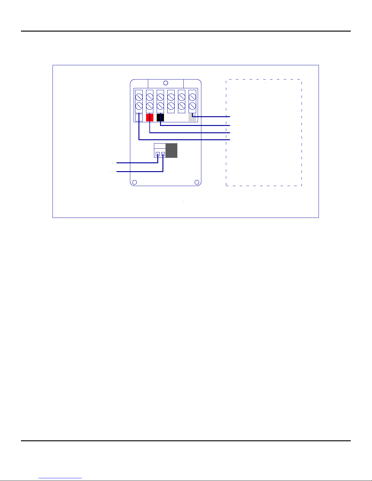
5 WIRING DIAGRAM
4-20 mA Loop +
4-20 mA Loop -
Analog Output
Evaporation Gauge
Model 255-100
Shield - Earth ground
Black - Reference
Red - Excitation
White - Signal in
2
1
255-100C-4 WIRING DIAGRAM
The Analog Output Evaporation Gauge (sold separately) includes 50 feet of shielded cable. The cable
can be extended up to a total of 250 feet if required. If the cable is extended be sure to spice the shield
also in order to reduce electrical noise.
CAUTION: Be sure to observe correct polarity when connecting to the 4-20 mA loop circuit. Internal
diodes will protect the Signal Conditioner if wired backwards, but the output will be meaningless.
Cable for connecting the 4-20 mA loop is not supplied. Use a wire gage adequate to provide a
minimum of 8 volts at the Signal Conditioner after voltage drop over the cable is accounted for. The
cable grips will accept 0.181" to 0.312" (4.6 to 7.9 mm) diameter cable.
6 CALIBRATION
When ordered together with an Analog Output Evaporation Gauge the 255-100C-4 Signal Conditioner
is individually factory calibrated to the Gauge. Recalibration is not necessary unless the Gauge is
replaced (see Appendix A for instructions).
At installation, the float/chain assembly of the Analog Output Evaporation Gauge must be correctly
installed on the gear, otherwise the sensor output will be meaningless. Instructions for setting the
position of the gear with respect to the chain are given in the 255-100 Analog Output Evaporation
Gauge manual.
200-100C-4 Page 7 September 2018
Page 8

NovaLynx Corporation
7 SINGLE-POINT OFFSET ADJUSTMENT
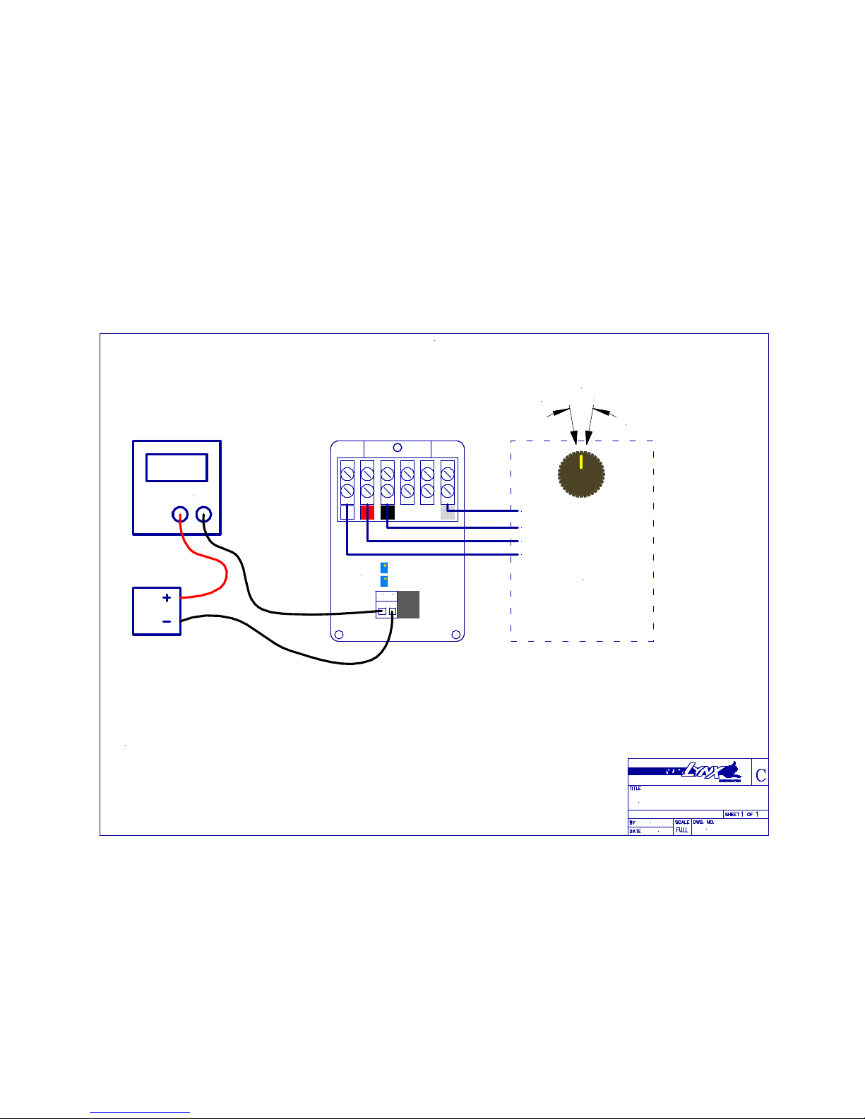
One can verify/adjust the output of the 255-100C-4 Signal Conditioner using either a 4-20mA calibrator
or good quality milliamp meter and 9 or 12 volt battery (see Appendix A for connections).
Measure the depth of the water in the Evaporation Pan and calculate the mA output using one of the
formulas below. Measure the mA output of the Signal Conditioner. If the results do not match then
move the chain one tooth clockwise or counterclockwise and recheck.*
Evaporation Pan Level in millimeters: mA = Depth (mm) x 0.063 + 4
Evaporation Pan Level in inches: mA = Depth (inch) x 1.6 + 4
* The gear has 40 teeth, so moving the chain 1 tooth raises or lowers the float 0.25" (6.35 mm). If finer
adjustment is needed it may be possible to program the offset in your monitoring equipment.
8 MAINTENANCE
The 200-100C-4 Signal Conditioner requires no maintenance under normal operating conditions. If any
problems with the signal are detected, check the following:
Inspect the cables for damage and repair as necessary.
Ensure there is no moisture buildup in the enclosure that houses the circuit board as this can
introduce error or damage the board.
Tighten the screw terminals if necessary.
Ensure power is getting to the board and the polarity is correct.
Check the operation of the Analog Output Evaporation Gauge using an ohmmeter (disconnect
the Gauge from the Signal Conditioner for this test)
Measure the water level depth and calculate the corresponding mA output. Adjust the chain if
necessary.
Perform the calibration procedure if required.
200-100C-4 Page 8 September 2018
Page 9
APPENDIX A
255-100C-4 WIRING DIAGRAM
JDC
09-20-2018
255-100C-4
Calibration Procedure
890-0020-01
1
2
White - Signal
Black - Reference
Shield - Earth ground
Red - Excitation
Analog Output
Evaporation Gauge
Model 255-100
mA COM
R28 GAIN
R26 OFFSET
20°
19.1 mA
4.0 mA
Dead Band
1) Connect a 9V or 12V battery and meter as shown.
2) Rotate the gear until the lowest mA reading is obtained. Adjust R26 OFFSET to 4.00 ±0.080 mA.
3) Rotate the gear counter-clockwise. The output will rise gradually until the dead band
is reached and then jump suddenly to 26-28 mA. Back off slightly to get out of the dead band
and adjust R28 GAIN to 19.1 ±0.080 mA.
4) There is a small interaction between the GAIN and OFFSET pots, so verify the lowest mA reading
is still 4.00 ±0.080 mA.
 Loading...