

Novak Tempest Max ESC User Manual

OPERATING INSTRUCTIONS
B
INTRODUCING THE TEMPEST
SPECIFICA TIONS
Part #1760
TEMPEST ACCESSORIES
The Novak Tempest Pro combines the power of HYPERFET
II transistors with full-digital micro-computer control to give
you the smoothest, fastest, and coolest speed control the
racing industry has to offer. Team driver or not!
The Tempest Pro features Novak’s exclusive Polar Drive
Technology™ that gives increased power with operating
temperatures cool enough that heat sinks are not needed.
This means smoother throttle response along with quicker
acceleration, increased radio system range, and longer run
times than conventional ESC’s (Electronic Speed Controls).
All this and the ability to run the hottest modified motors.
SIX HYPERFET II drive transistors and new Super-Flex 12™
wire give demanding racers the lowest voltage drop and
highest current rating in the industry, while THREE more
HYPERFET II’s supply the braking circuit with more power
than any other racing speed control.
Other features include the original One-Touch Set-Up™,
Radio Priority & Digital Anti-Glitch Circuitry™, the Novak
Input Plug System™, CLC II™ current limiter with ‘OFF’
position, ultra-light case design, and a heavy-duty BEC with
the power to handle today’s high power servos.
PRECAUTIONS
Input Voltage 4-10 cells (1.2 volts DC/cell)
Case Width 2.04 inches [51.82 mm]
Case Depth 1.35 inches [34.29 mm]
Case Height 0.73 inch [18.54 mm]
Weight (w/o heat sinks) 2.46 ounces [69.74 g]
On-Resistance
Rated Current 420 amps
Braking Current 210 amps
BEC Voltage 6.0 volts DC
BEC Current 5.0 amps
Wire Size (Battery/Motor) 12 gauge (Super-Flex 12™)
Wire Length
Signal Harness Length 8 inches [203 mm]
Transistor Type HYPERFET II™
Current Limiter Range 20 to 80 amps / OFF
PWM Frequency 2500 hertz (fixed)
Part Number 1760
@ Transistors 1.167mΩ
(Battery/Motor)
9 inches [228 mm]
@ 25°C transistor
junction temp.
RADIO INTERFERENCE
MOTOR CAPACITORS
To prevent radio interference problems, you must have
three 0.1µF capacitors properly installed on every motor .
Included with the Tempest Pro speed control are three
0.1µF (50v) capacitors for one motor. Additional 0.1µF
(50V) capacitors are available in Novak kit #5620. Refer
to Step 3 for motor capacitor installation instructions.
SCHOTTKY DIODES
The Tempest Pro uses an external Schottky diode. For optimum performance, we suggest installing the Schottky
diode on the motor. One Schottky diode is included with
the T empest and must be installed as described in Step 3.
If using a low turn modified motor, it may be necessary to
use two Schottky diodes on the motor. Install the second
Schottky diode as shown in Step 3. Additional Schottky
diodes are available in Novak kit #5640.
HEAT SINKS
Heat sinks are not required with the Tempest. However,
if transistors get excessively hot during operation, the
added cooling provided by heat sinks will result in a slight
increase in efficiency. An optional Heat Sink Set is available as Novak kit #5407. Heat sinks are recommended
for multi-motor/heavy load applications and set-ups with
limited air circulation.
• READ INSTRUCTIONS CAREFULLY BEFORE USING!
• WATER & ELECTRONICS DON’T MIX! Do not operate
model in or around water. Never allow water, moisture,
or other foreign materials to get inside the ESC.
• 4 to 10 CELLS ONLY Never use more than 10 cells (12
volts DC) in the main battery pack.
•
MOTOR CAPACITORS REQUIRED
ceramic capacitors must be properly installed on every
motor to prevent radio interference.
• NO REVERSE VOLTAGE! Reverse battery polarity can
damage speed control––Disconnect battery immediately.
• DON’T LET TRANSISTOR TABS TOUCH Never allow
the two transistor tab banks to touch each other or any
exposed metal, as this will create a short circuit and
age the speed control.
• DISCONNECT THE BATTERIES Always disconnect the
battery pack from the speed control when not in use.
• TRANSMITTER ON FIRST Always turn on the power of
your transmitter first so that you will have control of the
radio equipment when you turn on the speed control.
• DON’T LET INPUT WIRES TOUCH! Never allow the input
harness’ black and red wires touch each other while the ESC
is on, as this will create a short circuit and damage the ESC.
• INSULATE WIRES Always insulate exposed wiring with
heat shrink tubing to prevent short circuits.
Three 0.1µF (50V)
dam-
The high frequency switching operation of electronic
speed controls can generate radio interference. Here are
some common causes of radio interference problems:
• CAPACITORS NOT INSTALLED ON MOTOR Electric
motors generate radio noise that can interfere with the
receiver . T o prevent radio problems, every motor must
have three 0.1µF (50V) ceramic capacitors installed on
it. Refer to Step 3 on back page for proper installation.
• RECEIVER/ANTENNA INCORRECTLY MOUNTED The
receiver and antenna should be mounted as far from
the motor, power wires, battery, and servo as possible,
as these components all emit radio noise. On graphite
or aluminum, place receiver on edge with the crystal
and antenna as far above the chassis as possible. Mount
the antenna close to receiver and trail any excess wire
off the top of antenna. Do not cut or coil excess wire!
• MOTOR BRUSHES WORN As motor brushes continue
to wear, excessive motor noise will be generated. To
avoid radio interference, worn motor brushes should
be replaced. The motor commutator may also need to
be cleaned or trued and can be machined to help the
motor run more efficiently.
DETAILED INFORMATION
TEMPEST QUICK SET -UP
INSTALL SPEED CONTROL
A
Use double-sided tape to mount ESC in model where the
power wires are neatly routed away from the receiver and
antenna. For more details refer to Step 2 on back.
CONNECT SPEED CONTROL TO RECEIVER
B
Plug the ESC input signal harness into the throttle channel
of receiver. Make sure the proper plug plastic is installed
on ESC signal harness. Refer to Step 1 for changing plug.
CONNECT SPEED CONTROL TO BATTERY
C
Solder the BLACK wire of ESC to negative of a completely
charged 4 to 10 cell battery pack (1.2 volts DC/cell).
Strip a short section of insulation off the
where it will attach to battery positive.
Solder stripped section of
TURN ON TRANSMITTER POWER
D
Refer to Step 4 on back for transmitter adjustments.
TURN ON SPEED CONTROL
E
Slide ON/OFF switch to ON position.
PRESS AND HOLD SPEED CONTROL SET BUTTON
F
With transmitter throttle in neutral position, press and hold
SET button until status LED turns solid red, then release.
PULL THROTTLE TO FULL-ON POSITION
G
Hold until status LED turns solid green.
PUSH THROTTLE TO FULL-BRAKE POSITION
H
Hold until status LED blinks green, then return throttle to
neutral position. LED will then turn solid red indicating
proper programming and throttle is in neutral position.
CONNECT SPEED CONTROL TO MOTOR
I
Turn off speed control and then transmitter.
Solder the BLUE wire of ESC to motor negative.
Solder the end of the RED wire of ESC to motor positive.
STORM THE TRACK & WIN!
J
Turn on transmitter and then speed control.
You are now prepared to experience the smoothest
motor control, lowest voltage drop, and highest
current rating available in racing speed controls!
RED wire to battery positive.
RED wire of ESC
FOR DETAILED INFORMA TION REFER TO STEPS 1 THRU 5
E
blue
wire
F
red wire (+) (-) black wire
NOTE: The small
blue wire from the
ESC is for powering
a FET servo without
an external receiver
battery pack.
D
C
(+)
I
blue wire (-)
G
H
STEP 1
CHANGING THE INPUT PLUG
Included with the Tempest Pro is the Novak Input Plug
SystemTM to convert the Futaba J style signal harness to
be compatible with Airtronics, KO, Kyosho, JR, and Hitec
radios. Refer to Figures 1 through 3 to convert plug.
Airtronics (A) KO Kyosho (KYO) JR/Hitec
FIGURE 1 With a small standard screwdriver, press on
each of the three metal prongs until the wires are easy to
remove. Remove wires.
FIGURE 2 With the screwdriver, carefully lift up each of
the metal locking tabs to the angle shown.
FIGURE 3 Insert each pin into the correct plug slot. Each
pin should "click" into place.
(Airtronics plug shown)
WHT = White wire terminal (signal)
BLK = Black wire terminal (negative)
RED = Red wire terminal (positive)
CAUTION Improper installation or shortening of these wires
may cause damage to the receiver, servo, and speed control.
The locking tab must not extend
outside the plastic plug housing.
NOVAK ELECTRONICS, INC.
18910 Teller Avenue
Irvine, CA 92715
STEP 2
MOUNTING INSTRUCTIONS
1. DETERMINE BEST ESC MOUNTING LOCATION
The ESC should be positioned away from the receiver
and antenna as shown in Quick Set-Up photo on front
page. Choose a mounting position that will keep the
power wires as short as possible without obstructing
movement of the suspension or the motor pod.
Remember, even though heat sinks are not required,
cooler operating temperatures mean higher efficiency .
So choose a mounting position that allows maximum
airflow through the transistor tabs.
2. INSTALL SPEED CONTROL
Use the included double-sided tape to mount the ESC.
3. INSTALL ON/OFF SWITCH
Determine a convenient place to mount the switch
where it will be easy to get to. Mount the switch using
a piece of double-sided tape or with a screw through
the hole in the base of the switch housing.
4. INSTALL RECEIVER
Mount the receiver as far from the motor, power wires,
battery, and servo as possible. These components all
emit radio noise when the throttle is being applied.
On graphite or aluminum, place the receiver on edge
with the crystal and antenna as far above the chassis as
possible. Mount the antenna close to the receiver and
trail any excess wire off the top of the antenna tube.
STEP 3
HOOK-UP INSTRUCTIONS
Refer to Quick Set-Up photo on front
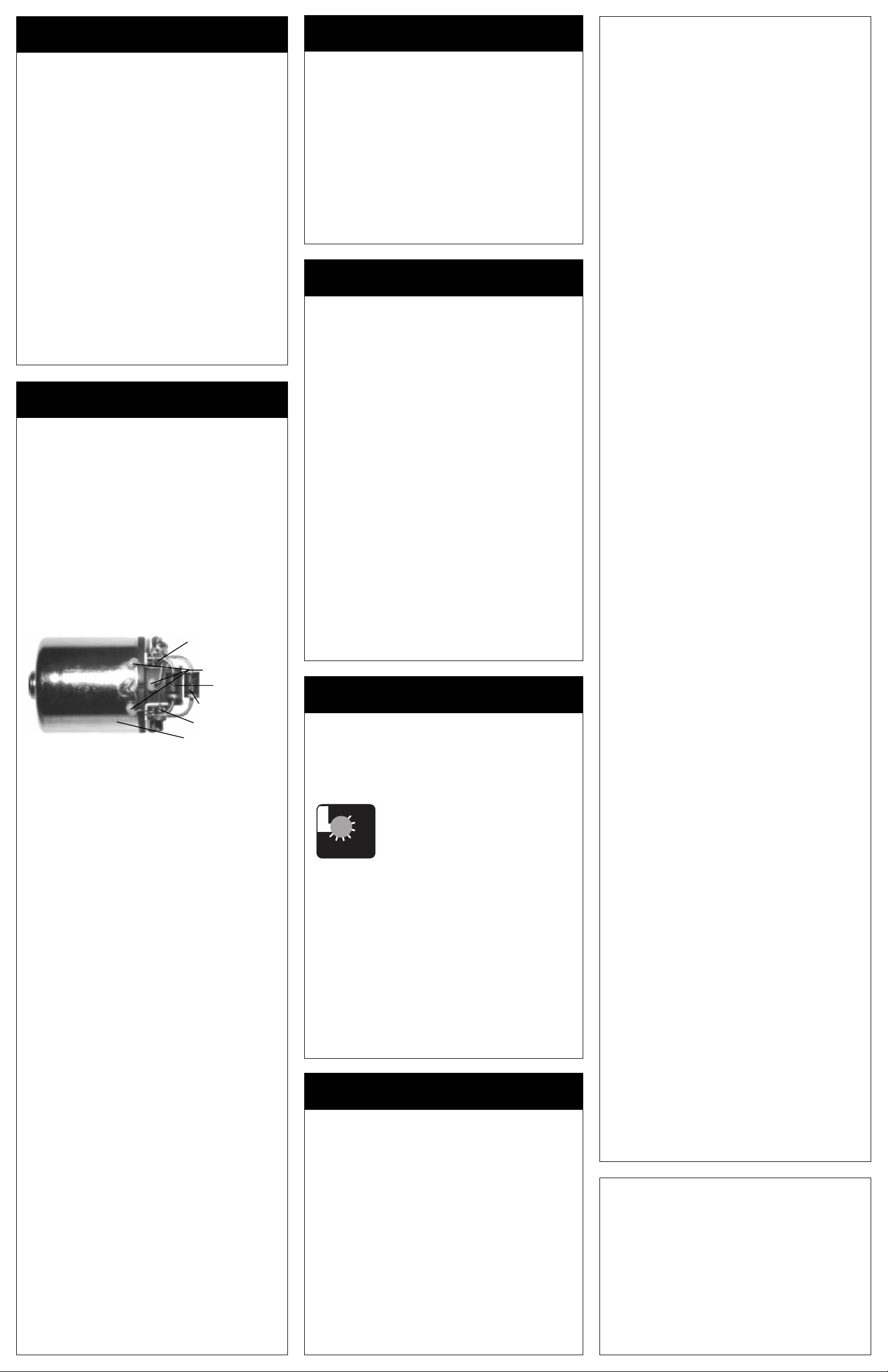
1. INSTALL MOTOR CAPACITORS
Electric motors generate radio noise that can interfere
with your receiver and cause radio problems. Included
in the accessory kit with the speed control are three
0.1µF (50V) non-polarized, ceramic capacitors. These
capacitors must be installed on every motor to help
reduce the noise generated by the motor and also to
prevent possible damage to the speed control. Extra
0.1µF capacitors are available in Novak kit #5620.
Solder 0.1µF (50V) capacitors between:
• POSITIVE (+) motor tab & NEGATIVE (
• POSITIVE (+) motor tab & GROUND tab*.
• NEGATIVE (
-) motor tab & GROUND tab*.
*If your motor does not have a ground tab, solder the
capacitor leads to the can of the motor as shown below .
* A second Schottky diode may be needed if using a low turn modified motor.
2. INSTALL SCHOTTKY DIODE
Solder the lead
CLOSEST to the silver stripe on the body
of the Schottky diode to the POSITIVE (+) motor tab.
Solder the lead
of the Schottky to the
If installed backwards, a Schottky diode will be destroyed. The
body of a bad diode will normally crack open. Replace only
with Schottky diodes that have a minimum rating of 35 volts/
8 amps. Schottky diodes are available in Novak kit #5640.
OPPOSITE the silver stripe on the body
NEGATIVE (-) motor tab.
3. CONNECT SPEED CONTROL TO THE RECEIVER
After the proper input plug plastic has been installed
to match the receiver (Refer to Step 1), plug the speed
control into the
THROTTLE CHANNEL of the receiver .
4. CONNECT SPEED CONTROL TO THE BATTERY PACK
Cut the
BLACK wire of speed control to the desired
length and strip about 1/4” of insulation off the end.
Solder to the negative side of a completely charged 4
to 10 cell battery pack (1.2 volts DC/cell).
Strip a short section of insulation (1/4”-3/8”) from the
middle section of the
RED wire of speed control where
it will attach to positive of battery pack. Solder the
stripped section of
RED wire to positive of battery pack.
5. CONNECT SPEED CONTROL TO THE MOTOR
Cut the
BLUE wire of speed control to the desired
length and strip about 1/4” of insulation off the end.
Solder to the negative tab of the motor.
Cut the
RED wire of speed control (after battery pack
connection) to desired length and strip about 1/4” of
insulation off the end. Solder to positive tab of motor .
TIP: Twisting the BLUE & RED motor wires one or two times
around each other as they go to motor can help reduce any
radio noise that may be emitted from the power wires.
6.
USING PLUGS FOR BATTER Y & MOTOR CONNECTION
High-quality/low-resistance connector plugs, such as
Dean’s Ultra Plugs, can also be used to connect the
motor and battery pack. While these connectors make
component changes quick and easy, the connection
will never have the low resistance of a good solder joint.
Be sure to use connectors that can not be connected
backwards, as this will damage the speed control.
It is good practice to use a female connector on the
main battery pack to keep the pack from shorting if
the connector touches a conductive surface.
If you plan to use connector plugs for the battery pack
and the motor, use a male connector on the speed
control wires going to the battery pack and a female
connector on the wires going to the motor . By doing
this, you will avoid plugging the battery pack into the
motor output of the speed control by mistake.
-) motor tab.
Negative (-) motor tab
0.1µF Capacitors
Schottky diode
Optional Schottky diode*
Positive (+) motor tab
Ground/motor can
STEP 4
TRANSMITTER ADJUSTMENTS
For proper ESC operation adjust transmitter as follows:
1. Set HIGH ATV or EPA to maximum setting.
[Amount of throw at full throttle]
2. Set LOW ATV, EPA, or ATL to maximum.
[Amount of throw at full brakes]
[Reduce this after programming to reduce amount of brakes]
3. Set EXPONENTIAL to zero.
[Throttle channel linearity]
4. Set THROTTLE CHANNEL TRIM to middle setting.
[Adjusts neutral position/Increases or decreases coast brakes]
5. Set CHANNEL REVERSING SWITCH to either position.
6. Set MECHANICAL THROW ADJUSTMENT to position
with 2/3 throttle and 1/3 brake throw.
[Adjusts pistol-grip transmitter’s throttle trigger throw]
STEP 5
SPEED CONTROL PROGRAMMING
Before beginning this step, the speed control should be
connected to the receiver and to a charged 4 to 10 cell
battery pack, and the transmitter should be adjusted.
1. TURN ON THE TRANSMITTER.
2. TURN ON THE SPEED CONTROL
Slide the
3. PRESS AND HOLD SPEED CONTROL’S SET BUTTON
With the transmitter throttle in the neutral position, press
and hold the
status LED turns solid red.
4. RELEASE SPEED CONTROL’S SET BUTTON
5.
PULL TRANSMITTER THROTTLE TO FULL-ON POSITION
Hold it there until the status LED turns solid green.
NOTE: The motor will not run during programming even if
it is connected to the speed control.
6. PUSH TRANSMITTER THROTTLE TO FULL-BRAKE
Hold it there until the status
7. RETURN TRANSMITTER THROTTLE TO NEUTRAL
The status
throttle is in the neutral position and also that proper
programming has been completed.
If transmitter settings are changed during programming,
it will be necessary to complete the programming sequence
once again. If you experience problems during programming, turn off the speed control and repeat programming.
ON/OFF switch to the ON position.
SET button on the speed control until the
LED blinks green.
LED will turn solid red, indicating that the
STEP 6
ADJUSTING THE CURRENT LIMITER
The Tempest Pro ESC is equipped with CLC II cur rent limiting circuitry. The current limiter pot contr ols the maximum
amount of current going to the motor upon acceleration.
CLC II can be used to prevent excessive amp draw which
wastes energy and overheats the batteries and motor . And,
for slippery tracks, CLC II can be used as traction control.
O
20
F
F
80
60
adjusting, set up the car similar to how it will be when
racing. Use practice time at the track to set the current
limiter to match track conditions.
• TO REDUCE WASTED ENERGY We recommend starting at a high level and adjusting downward to suit the
track conditions. The recommended setting is just above
the point where the CLC II starts reducing the acceleration of the motor.
• TO CONTROL TRACTION ON SLIPPERY TRACKS We
recommend starting at the lowest setting and adjusting
upward. The recommended setting is just below the point
where the car is difficult to control during acceleration.
• FOR MAXIMUM PUNCH Turn the knob to the "OFF"
position and punch the throttle!
The Tempest’s CLC II is smooth and efficient. The "OFF" position bypasses the
40
current limiter for maximum punch. Setting CLC II is simple, just turn the knob to
CL
the desired maximum amp draw. Before
RECEIVER BATTERY PACK
The Tempest Pro should not require an external r eceiver battery pack for most racing situations. The built-in Radio-Priority
Circuity™ provides complete control of the steering servo
even after the main battery pack has ‘dumped’ and can no
longer provide the power required to operate the motor.
However, applications using 4-cell set-ups, multiple high-powered servos, and main battery packs with 8 or more cells
require the use of an external receiver battery pack to prevent overloading or underpowering of the ESC’s voltage
regulator. Failure to use an external receiver battery pack in
these applications will damage the voltage regulator and void
the product warranty.
1. Plug the external 5 cell nickel cadmium receiver battery
pack into the battery slot of the receiver.
2. Leave the speed control’s ON/OFF switch in the OFF posi-
tion. This switch is not used with this configuration.
3. Use the ON/OFF switch on the external receiver battery
pack to turn the system power on and off.
Note: If using a FET servo with an external receiver battery pack, the
separate power wire from the servo must be connected to the red (positive) servo wire. For this application do not use the blue wire from the ESC.
TROUBLE-SHOOTING GUIDE
ESC Will Not Program Properly
• T oo little transmitter throw––Increase A TV/EP A setting.
• Make sure ESC is plugged into the throttle channel of
receiver . Check throttle channel operation with a servo.
• ESC SET button not held long enough––Press and hold
SET button until status LED turns solid red.
Steering Channel Works But Motor W ill Not Run
[Status LED is solid RED at all throttle positions]
• No signal from receiver––Make sure speed control is
plugged into throttle channel of receiver . Check throttle
channel operation with a servo. Check the wiring color
sequence of receiver harness.
Steering Channel Works But Motor W ill Not Run
[Status LED is RED at neutral / GREEN at full throttle]
• Check motor connections. Check motor and brushes.
Steering Channel Works But Motor W ill Not Run
• Not programmed––Repeat programming.
• Check wiring and connections––Check operation of
system without speed control.
Receiver Glitches/Throttle Stutters During Acceleration
• Motor capacitors broken or missing––Refer to Step 3.
• Receiver or antenna too close to speed control, power
wires, battery, or motor––Refer to Step 2.
• Bad connections––Check wiring and connectors.
• Excessive current to motor––Use a milder motor or a
smaller pinion gear.
ESC Is Melted Or Burnt/ESC Runs With Switch Off
• Internal damage––Refer to Service Procedures.
*For more help call our Customer Service Department.
SERVICE PROCEDURES
Before sending in your Tempest Pro for service, review
the T rouble-Shooting guide and the instructions. The ESC
may appear to have failed when other problems exist.
PLEASE NOTE: Speed controls that operate normally
when received will be charged a minimum service fee
and return shipping costs.
WHA T TO SEND: Fill out all of the information requested
on the enclosed ESC SERVICE CARD and return it with
your speed control.
WARRANTY WORK: For warranty work, you MUST CLAIM
WARRANTY on the ESC SERVICE CARD and include a valid
cash register receipt with the purchase date on it, or an
invoice from previous service work. If warranty provisions
have been voided there will be a service charge.
SERVICE COSTS: Customer is responsible for all service
costs (parts, labor, and shipping/handling charges). Speed
controls are returned by UPS/COD CASH ONLY. See ESC
SERVICE CARD for other payment and shipping options.
ADDITIONAL NOTES:
• Hobby dealers/distributors are not authorized to replace
speed controls thought to be defective.
• If a hobby dealer sends your speed control for service,
submit a completed ESC SERVICE CARD to the dealer
and make sure it is sent with the speed control.
• To provide the most efficient service possible to our
customers, it is not our policy to contact customers by
phone or mail.
•
Novak Electronics, Inc. does not make any electronic
compo
nents (transistors, resistors, etc.) available for sale.
PRODUCT WARRANTY
Novak Electronics, Inc. guarantees the Tempest Pro to be free
from defects in materials or workmanship for a period of 90 days
from original date of purchase
ceipt)
. Warranty does not cover incorrect installation, components
worn by use, damage from using less than 4 or more than 10
cells
(1.2 volts DC/cell)
cross-connection of battery/motor, reverse voltage application,
damage resulting from thermal overload, damage from incorrect
use of an external receiver battery pack, damage from incorrect
installation of FET servo or receiver battery pack, damage from
excessive force while installing heat sinks, not installing
(50V) capacitors and a Schottky diode on motor, splices to input
or switch harnesses, damage from excessive force when using
SET
button or current limiter or from disassembling case, tampering with internal electronics,
foreign material to enter
installation of alternate
ing to short-circuit, or any damage caused by a crash.
In no case shall our liability exceed product's original cost. We
reserve the right to modify warranty provisions without notice.
Because Novak Electronics, Inc. has no control over connection
and use of the ESC, no liability may be assumed nor will be accepted for damage resulting from the use of this product. Every
ESC is thoroughly tested and cycled before leaving our facility
and is, therefore, considered operational. By the act of
ing/operating ESC, the user accepts all resulting liability.
input voltage, short-circuiting heat sinks,
(verified by dated, itemized sales re-
three 0.1µF
allowing water, moisture, or any other
ESC or get onto PC board, incorrect
input plug plastic, allowing exposed wir-
connect-
CUSTOMER SERVICE
CUSTOMER SERVICE HOURS (PST)
Monday-Friday: 8:00am-4:00pm
(714) 833-8873 • FAX (714) 833-1631
©1996 Novak Electronics, Inc. • All Rights Reserved
No part of these operating instructions may be reproduced without the
written permission of Novak Electronics, Inc.
All Novak speed controls are designed and manufactured in the U.S.A.
Tempest Pro™, HYPERFET II™, Polar Drive T echnology™, One-T ouch Set-
Up™, Radio Priority Circuitry™, Digital Anti-Glitch Circuitry™, and Input
Plug System™ are all trademarks of Novak Electronics, Inc.
Printed in the U.S.A. 3/96 • #IM-1760-2
 Loading...