

Novak SUPER SPORT User Manual
SENSOR-BASED
INSTRUCTION MANUAL
BRUSHLESS MOTOR SYSTEM
How do you make a great hobby even more fun?
Eliminate motor maintenance & increase efficiency.
We’ve done it! People have seen the benefits of brushless
motor systems in many industries--now you too will enjoy
the maintenance-free, high-efficiency performance of
brushless that is designed specifically for your R/C car.
We combined the racing technology of our top of the line
speed controls with the efficiency of sensor-based brushless
motors to bring you the Super Sport Brushless Motor System,
giving you a sport-level brushless system with excellent low
speed driveability, extended run time, great torque available
over a broad power band, and Novak relaibility.
Equipped with Novak’s Variable Throttle Step Technology
for the smoothest throttle response, One-Touch Set-Up for
ease of programming, and the security of Radio Priority
Circuitry, the Super Sport has it all!
SPECIFICATIONS
Input Voltage 4-7 cells (1.2 volts DC/cell)
ESC Case Width 1.32” [33.5 mm]
ESC Case Depth 1.75” [44.4 mm]
ESC Case Height 1.05” [26.7 mm]
ESC Weight (w/o wires) 1.70 ounce [48.2 gr]
ESC Power Rating 225 Watts @ 25
°
C trans.temp.
B.E.C. Voltage 6.0 volts DC/3.0 amps
Wire Length (Battery/Motor) 9 inches
Signal Harness (replaceable) 9 inches
[22.86 cm]
[22.86 cm]
ESC Throttle Programs 6 (3 w/Rev. & 3 Fwd/Brk)
Motor Diameter 1.41” [35.8 mm]
Motor Length 2.08” [52.8 mm]
Motor Weight 6.40 ounce [181.4 gr]
Motor Power Rating 196 Watts
Motor Kv 5800 RPM/Volt DC
Motor Kt 0.45 Inch-Ounce/Amp
Motor Commutation Sensor-Based Electronic
Motor Magnet Material Neodymium
(1pc/multi-pole)
PRECAUTIONS
• WATER & ELECTRONICS DON’T MIX! Never allow
water, moisture, or other foreign materials to get inside
the speed control, motor, or on the PC Boards.
• CHECK MOTOR SCREWS Remember to check all motor
screws for loosening. The 3 main 4-40 socket head screws
on the shaft end of the motor may become loose after a
few runs of the motor, and will need to be tightened.
• 4 TO 7 CELLS ONLY Never use fewer than 4 or more
than 7 cells (8.4 volts DC) in the main battery pack.
• POWER CAPACITOR REQUIRED The attached external
power capacitor MUST be used with the Super Sport.
Failure to use Power Capacitor will damage speed control
and void the warranty!
• NOVAK MOTORS ONLY The Super Sport ESC has been
specially designed for use with sensor-based Novak
Brushless Motors Only! You may replace motor with any
Novak sensored motor rated less than 225W (ESC’s rating).
• NO REVERSE VOLTAGE! Reverse battery polarity will
damage the speed control.
• DISCONNECT BATTERIES WHEN NOT IN USE Always
disconnect the battery pack from the speed control when
not in use to avoid short circuits and possible fire hazard.
• TRANSMITTER ON FIRST Always turn on the power of
your transmitter first so that you will have control of the
radio equipment when you turn on the speed control.
• INSULATE WIRES Always insulate exposed wiring with
heat shrink tubing to prevent short circuits.
• NO SOLVENTS Exposing the speed control or motor to
any type of solvents can damage the exposed material.
SENSOR-BASED DESIGN
The benefits of a sensor-based brushless motor design are:
• CONSTANT ROTOR POSITION KNOWLEDGE Always
knowing what angle the rotor is at, allows instantaneous
response and smooth transitions from neutral to drive.
• SMOOTH/CONTROLLED LOW SPEED DRIVEABILITY
Rotor positioning is key to smooth acceleration without
delivering abrupt and uncontrolled bursts of power.
• STRONG & CONSISTENT BRAKES & STARTING TORQUE
Again, rotor position knowledge results in consistent starts
and stops, without hesitation or inconsistent lag times
before acceleration or braking.
• LOCKED ROTOR & THERMAL PROTECTION Position
and temperature sensors inside motor provide
unparalleled thermal protection for your investment, while
allowing you to run pack after pack without worrying
about overheating the motor, ESC, or magnets.
Part #3005
STEP 1
The Super Sport ESC comes with the industry standard
nector on a user-replaceable input harness. This connector
works with all major radio brands. However, with some older
style receivers, the wiring sequence in the
must be changed. This is an important step, because the
receiver electronics may be damaged if the sequence is incorrect.
JR • Hitec • Futaba • New KO • Airtronics Z
JR, Hitec, Futaba, new KO, & Airtronics Z receivers
need to have the ESC’s input harness wire sequence changed
New Airtronics Z receivers have blue plastic cases & new KO
cases have tabs on the input harness openings as in Figure 1.
• Insert one end of the input harness into receiver with the
BLACK wire toward the outside edge of receiver case.
• Insert opposite end of input harness into ESC with the
WHITE wire toward the ‘S’ (signal) marking in the ESC’s case.
New KO Rx (with tabs) Old KO Rx (no tabs)
tabs
white
red
FIGURE 1
black
Old-style KO • Old-style Sanwa/Airtronics
If your receiver is an older KO or Sanwa/Airtronics, you must
change the sequence of the ESC’s input harness wires.
Old Sanwa/Airtronics cases are black in color & Old KO cases
do not have the tab openings, as in Figure 2 above.
• Insert one end of input harness into ESC with the WHITE
wire toward the ‘S’ (signal) marking in the ESC’s case.
• Interchange the red and black wires in the plug plastic at
the opposite end of the input harness as in Figure 3 below.
• Insert modified end of the harness into the receiver with
the RED wire toward the outside edge of receiver case.
FIGURE 3 With a small standard screwdriver, gently lift plastic
prong until wire and metal socket easily slide out of plastic housing.
CHANGING ESC’S INPUT HARNESS
con-
plastic connector
do not
.
no tabs
white
black
FIGURE 2
red
SUPER SPORT SET-UP
SUPER SPORT SET-UP
STEP 3
1. MOTOR CAPACITORS & SCHOTTKY NOT NEEDED
Novak brushless motors have built-in motor capacitors,
and like all reversible ESCs, does not use an external
Schottky diode--Schottky diodes damage reversible ESCs.
2. FACTORY-INSTALLED POWER CAPACITOR
WHY POWER CAPACITOR IS NEEDED: The Power Capacitor
drops ESC operating temperatures by 10-15°F and dissipates noise
& voltage spikes from the ESC’s high switching speed. You MUST
use Novak capacitors, because other capacitors with similar ratings
will not provide the same protection. We have done extensive
research to find capacitors with the very best Quality Factors.
Mount Power Capacitor using the included slide-mount
bracket or double-sided tape. To use slide mount bracket,
insert bracket into the channel on the back of the ESC,
and secure Power Capacitor with the included tie-wraps.
3. CONNECT SPEED CONTROL TO RECEIVER
Configure input harness wires and connect ESC to the
THROTTLE CHANNEL of receiver as described in Step 1.
4. CONNECT SPEED CONTROL TO BATTERY PACK
Connect Super Sport’s Tamiya-style JST battery connector
a charged 4 to 7 cell battery pack.
to
5. CHECK MOTOR SCREW LENGTH
Insert the M3 motor mounting screws that came with
your vehicle through the motor mounting plate in vehicle
You need to have about 1/8” (±1/32”) of the screw
extending past the mounting plate (2-4mm). Any less
can strip the threads in the motor’s end bell, and any
more will cause short-circuiting/damage inside the motor.
6.
INSTALL PINION GEAR
Install pinion gear on motor and position set-screw over
flat on end of shaft. Test fit motor in vehicle to align
pinion and spur gears, then tighten pinion gear on shaft.
7. INSTALL MOTOR IN VEHICLE
• Determine the best routing for sensor harness & motor
power
wire. Some off-road cars may require unsoldering
motor to route wires through the shock tower--refer to
Step 7, #3–”
• Using the M3 motor screws that came with your
vehicle, attach motor to vehicle’s motor mount using
one of the three sets of threaded mounting holes--
a mounting position that will avoid short-circuiting of solder
tabs on conductive surfaces such as aluminum or graphite.
• Check gear mesh for proper amount of play. You want
to have a small amount of free play between the pinion
and spur gears
free play at several positions around the spur gear.
• Avoid using excessive force when tightening motor
screws, as the threaded holes could become stripped.
8. USE SPIRAL WRAP TO BUNDLE/PROTECT WIRES
The included plastic spiral wrap can be used to protect
the 6 Teflon sensor harness wires between the ESC & motor
You can also use the included spiral wrap and tie-wraps to
bundle the sensor harness & power wires neatly together.
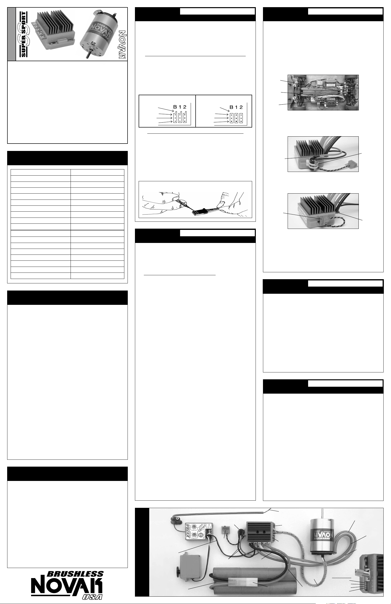
Keep receiver & antenna
as far from motor, servo,
battery, & power wires
as possible.
User-replaceable
input signal
harness plugged
into throttle
channel (#2).
SET-UP PHOTO
BASIC HOOK-UP INSTRUCTIONS
(see GEAR SELECTION on back)
SOLDERING POWER WIRES AT ESC & MOTOR”.
select
(about the thickness of piece of paper)--check
Power Capacitor
tie-wrapped to
slide-mount bracket
O
N
sw
/O
itch
FF
plugged
steering
ch. (#1)
4 to 7 cell
battery pack
Servo
into
PowerCap
(–)
(+)
wires
Black power wire
(battery negative)
.
.
STEP 2
1. DETERMINE BEST ESC MOUNTING LOCATION
Choose a mounting position that keeps power wires away
from the receiver and antenna, and will provide
maximum airflow over heat sinks for proper cooling.
The slide mount channel on the back of the Super Sport’s
case can hold the ON/OFF switch or power capacitor.
T
his slide mount lets you mount the power capacitor or the ON/OFF
switch against the side of ESC. The ON/OFF switch
facing any of four directions when held by the slide mount. The
switch also has a hole for attaching it with a 4-40 or smaller screw,
or you can use the included double-sided tape.
motor
phase wires
&
sensor harness
ESC
2. SLIDE-MOUNT POWER-CAP. BRACKET (optional)
To use the included P.Cap bracket to mount the capacitor on the back
of the ESC, be sure you have enough space in the desired location.
Slide the bracket into the channel on the ESC. Secure the
power capacitor to the bracket with the included tie-wraps.
heat shink
&
vinyl tubing
insulating
capacitor
leads
3. INSTALL THE SPEED CONTROL & SWITCH
If using the slide mount channel to hold ON/OFF switch,
slide switch into channel
Mount the ESC using the included double-sided tape.
slide-mount
switch
4. INSTALL THE RECEIVER AND ANTENNA
Mount receiver as far from ESC, motor, power wires,
battery, and servo as possible. These components all emit
RF noise when throttle is being applied. On graphite
aluminum, it may help to place receiver on edge with
crystal and antenna as far above chassis as possible.
Note: Mount the antenna as close to the receiver as possible, and trail
any excess wire off the top of the antenna mast––cutting or coiling the
excess antenna wire will greatly reduce radio range.
MOUNTING SPEED CONTROL
can be positioned
Super Sport
brushless
system
installed in
Tamiya
touring sedan
for first win
@ Tamiya
4 hour
Enduro Race
power
capacitor
tie-wrapped
to bracket
facing the desired direction.
solder tabs
or
SUPER SPORT SET-UP
SUPER SPORT SET-UP
STEP 4
For proper ESC operation, adjust transmitter as follows:
A. Set HIGH ATV or EPA to maximum setting.
[amount of throw at full throttle]
B. Set LOW ATV, EPA, or ATL to maximum setting.
[amount of throw at full brakes]
C. Set EXPONENTIAL to zero setting.
[throttle channel linearity]
D.
Set THROTTLE CHANNEL REV. SWITCH to either position.
E. Set THROTTLE CHANNEL TRIM to middle setting.
[adjusts neutral position/increases or decreases coast brakes]
F. Set ELECTRONIC TRIGGER THROW ADJUSTMENT to
70% throttle and 30% brake throw (or 7:3).
[adjusts trigger throw electronic/digital pistol-grip transmitters]
G. Set MECHANICAL TRIGGER THROW ADJUSTMENT
to position with 2/3 throttle and 1/3 brake throw.
[adjusts trigger throw on mechanical/analog pistol-grip transmitters]
TRANSMITTER ADJUSTMENTS
SUPER SPORT SET-UP
STEP 5
With ESC connected to receiver & a charged battery pack:
1. TURN ON THE TRANSMITTER’S POWER
2. PRESS & HOLD SPEED CONTROL’S SET BUTTON
3. TURN ON THE SPEED CONTROL’S POWER
With transmitter throttle at neutral, and still pressing the
SET button slide the ON/OFF switch to ON position.
4. HOLD ESC’S SET BUTTON UNTIL RED LED IS ON
Continue pressing SET button until the Super Sport’s red
status LED turns solid red.
5. RELEASE ESC’S SET BUTTON WHEN LED IS RED
6. PULL TRANSMITTER THROTTLE TO FULL-ON POSITION
Hold it there until the green status LED turns solid green.
Note: Motor will not run during programming even if connected.
7. PUSH TRANSMITTER THROTTLE TO FULL-BRAKES
Hold it there until the green status LED blinks green.
8. RETURN TRANSMITTER THROTTLE TO NEUTRAL
Amber, green, & red status LEDs will turn on solid,
indicating that
ESC returns to neutral and red status LED will turn on solid.
NOTE: If transmitter settings are changed, programming must be repeated
If you experience any problems, turn off ESC and repeat programming.
Trail excess wire off top
of antenna mast
Status LEDs
One-Touch
Set-Up
button
Tamiya-style
battery connector
ONE-TOUCH PROGRAMMING
proper programming has been completed.
Orange power wire
(motor phase ‘C’)
Blue power wire
(motor phase ‘A’)
Yellow power wire
(motor phase ‘B’)
Sensor
Harness
bundled with
Spiral Wrap
Red power wire
(battery positive)
ESC faceplate
close-up
Status LEDs:
Blue LED
Amber LED
Green LED
Red LED
•NOT ALL TRANSMITTERS HAVE THESE ADJUSTMENTS
•
.
STEP 6
The Super Sport is equipped with 6 user-selectable Throttle
Programs to choose from, as shown in the chart below.
THROTTLE PROGRAM SELECTION
THROTTLE PROGRAMS
OPTIONAL SET-UP
SS STANDARD
123456
RPM**
Acceleration* unlim. unlim. unlim. unlim. fixed fixed
Min.Brake
w/Reverse
**Unlimited RPM is based upon motor’s rating. 5800Kv motor produces
41760 RPM @ 7.2 volts DC.
*Unlimited acceleration refers to acceleration only being limited by the
quality of the batteries used. Fixed acceleration is accomplished by only
allowing a factory programmed acceleration rate--all Super Sport ESCs
are programmed with the same fixed acceleration rate for programs 5 & 6.
unlim. unlim. unlim. umlim. 24000 24000
low low high high low low
yes no yes no yes no
Selecting Throttle Program--TRANSMITTER ON
With transmitter ON & ESC connected to receiver and battery:
1. TURN ON THE SPEED CONTROL’S POWER
2. PRESS & HOLD SPEED CONTROL’S SET BUTTON
With transmitter throttle at neutral, press and hold SET
button on Super Sport until all 4 LEDs turn on.
3. RELEASE SPEED CONTROL’S SET BUTTON
All status LEDs will flash together. The number of times
the LEDs flash indicates the Throttle Program selected.
4. PRESS & RELEASE SET BUTTON TO SELECT PROGRAM
Each press will change to the next consecutive Program
number.
(After Program #6, the sequence begins again at Program #1)
5. WAIT FOR SPEED CONTROL TO EXIT PROGRAMMING
When SET button is not pressed for about 3 seconds, the
ESC loads the selected Program into memory and exits
programming--red status LED will turn solid red indicating
that the speed control is at neutral and ready to go.
Selecting Throttle Program--WITHOUT TRANSMITTER
With the transmitter power OFF (or input harness disconnected):
1. TURN ON THE SPEED CONTROL’S POWER
When speed control is powered on and no input signal
is being received from the receiver, the green and red
status LEDs will both turn on solid. This acts as a system
check at all times to let you know the condition of the
connection between your receiver and the Super Sport ESC.
2. PRESS & HOLD SPEED CONTROL’S SET BUTTON
Press and hold SET button on ESC until all 4 LEDs turn on.
3. RELEASE SPEED CONTROL’S SET BUTTON
All status LEDs will flash together. The number of times
the LEDs flash indicates the Throttle Program selected.
4. PRESS & RELEASE SET BUTTON TO SELECT PROGRAM
Each press will change to the next consecutive Program.
5. WAIT FOR SPEED CONTROL TO EXIT PROGRAMMING
SET button not pressed for 3 sec.--ESC exits programming.
STEP 7
1.
REPLACEMENT POWER CAPACITOR INSTALLATION
•
Insulate capacitor’s leads with the heat shrink tubing
included in the accessory kit.
• Solder capacitor’s NEGATIVE (–) lead {shorter lead on
capacitor} to the Super Sport’s BLACK PowerCap wire
that comes from the small hole on Super Sport’s Battery
Negative (–) solder tab.
Solder capacitor’s POSITIVE (+) lead to RED PowerCap wire
•
that comes from the small hole on Super Sport’s Battery
Positive (+) solder tab.
2. HARD WIRING ESC TO BATTERY PACK
•
Cut Super Sport’s BLACK power wire to desired length
and strip
battery NEGATIVE (–) of a charged 4 to 7 cell pack.
•
Cut RED power wire to desired length
of insulation off the end. Solder to battery POSITIVE (+)
3. SOLDERING POWER WIRES AT ESC & MOTOR
The Super Sport ESC comes factory wired to the brushless
motor & battery connector. For custom installation or
for power wire replacement:
• Remove power wires from PCB solder tabs
be removed from the model so that you can get access to bottom
side of solder tabs). Use a soldering iron to apply heat to
the power wire’s solder joint on the bottom side of the
solder tab, while gently pulling up on the wire to
remove it from the hole in the PCB.
• Replace power wires by stripping 1/8-1/4” of
insulation from the end of the new wire. Tightly twist
strands of wire, and insert into proper solder tab’s hole
(tabs are identified by lettering that is engraved in the ESC
case and on the end cap of the motor--see photos
Use soldering iron to apply heat to exposed wire
extending past bottom of PCB, and begin adding solder
to tip of soldering iron and to wire. Add just enough
solder to form a clean & continuous joint from the plated
area of solder tab up
trim remaining
tab
strayed to an adjacent solder tab as this can result in short-circuiting
& damage to the electronics, which will void the product’s warranty
motor
&
battery
PCB tab
I.D. text
• Note: Power wires can also be soldered flat onto the
PCB solder tabs. Strip 3/16-1/4” of insulation from the
end of the new wire. Tightly twist strands of wire, and
tin with solder. Lay the stripped & tinned end of the
wire flat onto the PCB solder tab and use soldering
iron to heat the end of the wire, and add solder to
form a clean solder joint between the wire and the tab.
I
MPORTANT NOTE: DO NOT OVERHEAT SOLDER TABS
Prolonged/excessive heating of solder tabs will damage PCB.
4. CHANGING BATTERY CONNECTOR
If you are planning to change the ESC’s Tamiya-style
battery pack connector, we recommend using a highquality/low-resistance connector, such as Dean’s Ultra Plug
Always use a connector that can not be connected backwards!
1/8-1/4” of insulation off the end. Solder to
(now soldered)
(about 1/16” above PCB)
•Be sure to solder wires to matching tabs at ESC & Motor
SS HIGH
SPORTSMAN
OPTIONAL SET-UP
OPTIONAL HOOK-UP INSTR.
and strip 1/8-1/4”
(ESC must
below)
that is
onto the wire. Use side cutters to
wire from below the solder
--
make sure no strands of wire have
(A/B/C)
A
B
C
motor
phase
wire
tab I.D.
text
.
.
.
•
.
STEP 8
If you experienced any problems while performing the
One-Touch programming in Step 5, use the following
procedure to check that your transmitter has adequate throw.
With transmitter ON, ESC OFF & connected to receiver & battery:
1. PRESS & HOLD SPEED CONTROL’S SET BUTTON
2.
TURN ON SPEED CONTROL’S POWER
3.
HOLD SET BUTTON UNTIL BLUE, AMBER, & RED LEDs ON
4. RELEASE SPEED CONTROL’S SET BUTTON
Once blue, amber, & red LEDs (left 2 LEDs + right LED) turn on,
release the Super Sport’s SET button. Red LED will stay on.
5. PULL TRANSMITTER THROTTLE IN DRIVE DIRECTION
Slowly pull throttle toward full drive––blue LED blinks until 500µS of
throw is reached when it turns solid. (refer to Step 4/A to adjust throw)
6. PUSH TRANSMITTER THROTTLE IN BRAKE DIRECTION
Slowly push throttle toward full brake––amber LED blinks until 200µS of
throw is reached when it turns solid. (refer to Step 4/B to adjust throw)
Note: Without transmitter adjustments mentioned in Step 4/A & 4/B, ESC
will still program & operate normally with a minimum of ±90µS of throw.
GEAR SELECTION
As a general rule, you can start with the same gear ratio
that you previously had with a “stock” brush-type motor in
your vehicle. The difference is that you now have broad
power band, and can base your gear selection on application
instead of being limited to the narrow RPM range that your
brush-type motor produced its maximum
final drive ratios will give longer run time at the expense
speed, while
the ESC,
You will want the final drive ratio in the vehicle
{
If you had a modified brush-type motor in your
vehicle before switching to the Super Sport system
and you do not change the gearing, you will be
under-geared and the vehicle will appear slow!
ratios
and may result in overheating and thermal shut-down.
to be about 7.3:1 and not less than 6.5:1
CHECKING TRANSMITTER THROW
(while holding SET button)
(Important)
torque. Higher
of top
below 6.5:1 will cause excessive heating of
}
,
LOCKED ROTOR DETECTION
OPTIONAL SET-UP
The Super Sport system is equipped with Lock Rotor
Detection Circuitry that provides added protection against
overheat damage. Should the vehicle’s drive train become
locked or bound, or for any reason the motor shaft becomes
locked while the throttle is being applied for an extended
period, the Super Sport speed control will cut throttle power
to the motor. This situation could occur when the vehicle
becomes stuck against a tree or wall or jammed underneath
something where the wheels will not spin.
To indicate a locked rotor condition, the Blue & Green status
LEDs will flash six times and then remain on solid. The
transmitter’s throttle trigger must then be returned to the
neutral position before motor control is regained.
THERMAL SHUT–DOWN
The Super Sport system is equipped with temperature sensors
in both the ESC and motor to protect from overheating.
Should the ESC or motor become overheated for any reason,
the Super Sport ESC will cut throttle power to the motor.
To indicate thermal shut-down, the Blue status LED will flash
until the ESC or motor returns to within the normal operating
range, at which time throttle power is regained. The
transmitter’s throttle trigger must first be returned to the
neutral position before motor control is regained.
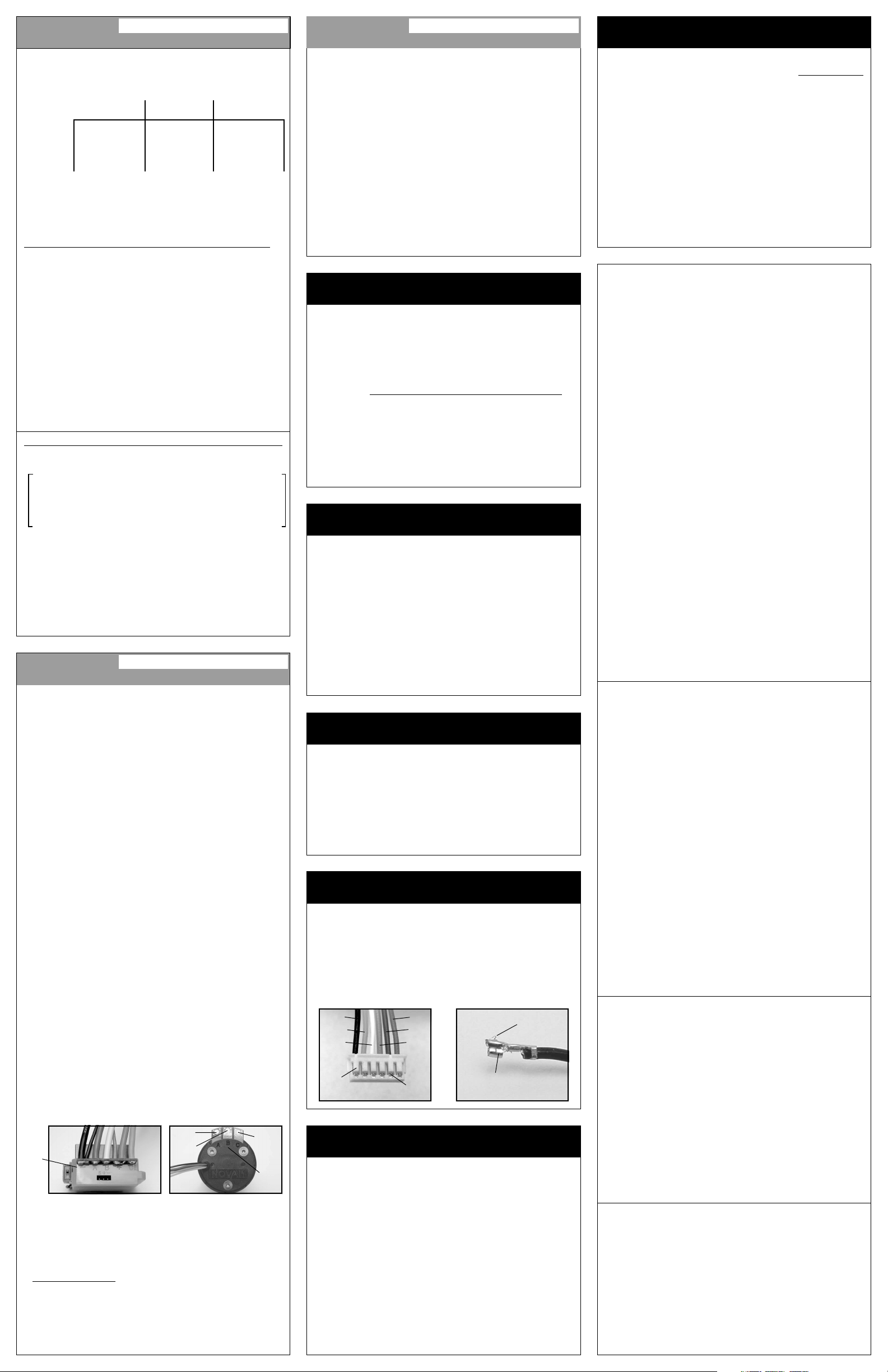
SENSOR HARNESS WIRING
Should any of the 26G Teflon wires pull out of the connector
on the end of the motor’s sensor harness, replace them into
the appropriate slot in the connector as shown below. The
connector has small plastic tabs that grab a small raised barb
on the back of the metal socket that is crimped onto the ends
of the Teflon wire. The plastic tab should be checked to make
sure it has not deformed excessively before inserting the
socket into the plastic connector housing.
harness become damaged, contact our Customer Service Department.
black
orange
white
plastic
tabs
red
blue
green
metal
barbs
If the motor’s sensor
raised
metal
metal socket
on end of Teflon
sensor harness wires
barb
MOTOR MAINTENANCE
• CHECK MOTOR SCREWS Check all motor screws for
loosening at regular intervals, just like other hardware on
your vehicle.
shaft end of the motor may become loose after a few runs of the
motor and will need to be tightened.
screws securing the end cap on the back of the motor.
• CHECK MOTOR BEARING WEAR After extensive use,
the ball bearings in the end bells of your brushless motor
may need to be replaced
will keep the majority of the debris out of the bearings, some
debris may get in, and eventually wear will occur. If the shaft
will not spin freely, you may need to replace the motor
bearings
kit #5900 and include bearing replacement instructions--If you do not
feel comfortable changing the bearing on your own, please contact
our Customer Service Dept. for assistance). A drop of light oil on
the bearings periodically can help extend bearing life.
Note: The 3 main 4-40 socket head screws on the
Also check the 3 flat head
. While the design of the motor
(replacement bearing sets are available in Novak accessory
ACCESSORIES
POWER CAPACITORS
An external power capacitor is included, and MUST BE USED
to maintain cool and smooth operation. Refer to Step 3
Replacement Power Capacitor is available in Novak kit #5677.
BATTERY/MOTOR 14G POWER WIRE
Replacement silicone power wires for your brushless motor
system
are available in Novak kits #5500 (36”red/36”black),
(36”red/36”blue), & #5510 (36”yellow/36”orange), or
#5505
(2 each of 9”red/black/blue/yellow/orange).
#5508
INPUT SIGNAL HARNESS
The user-replaceable input signal harness is available in both
short (4.5”) and long (9.0”) lengths to fit different applications.
4.5” harness in Novak kit #5315, and 9.0” harness in kit #5320.
MOTOR BALL BEARING SET
After extensive use, the ball bearings in the end bells of
your brushless motor may need to be replaced
Two replacement motor bearings are available in Novak kit #5900.
TROUBLE-SHOOTING GUIDE
This section describes possible ESC problems, causes, and solutions.
Steering Channel Works But Motor Will Not Run
• Make sure motor sensor harness is plugged into ESC––check
for damaged wires. Green & red status LEDs will be blinking fast.
•
Make sure input signal harness is plugged into throttle channel
of receiver & ESC. Check throttle channel operation with a
servo. Check wiring sequence of receiver signal harness. Green
& red status LEDs will be both be on solid.
• ESC may have shut down due to thermal overload or locked
rotor detection & ESC’s neutral point is too far off to sense
that throttle has been returned to neutral.
Blue & green status LEDs on solid indicates Locked Rotor
Detection. Blue LED blinking indicates thermal shut-down.
• Possible internal damage––Refer to Service Procedures.
Receiver Glitches/Throttle Stutters During Acceleration
• Receiver or antenna is too close to speed control, power wires,
or battery––Refer to Step 2.
• Bad connections––Check wiring and connectors.
• External Power Capacitor damaged/not installed––Refer to
Steps 3&7/Replace Power Capacitor (possible internal damage).
Motor and Steering Servo Do Not Work
• Check wires, receiver signal harness wiring and color
sequence, radio system, crystals, battery and motor
connectors, and battery pack.
• Possible internal damage––Refer to Service Procedures.
Speed Control Runs Hot
• Gear ratio too low––Increase ratio (see ‘GEAR SELECTION’).
Model Runs Slowly/Slow Acceleration
• Gear ratio too high––Reduce ratio (see ‘GEAR SELECTION’).
• Check battery connectors––Replace if needed.
Incorrect transmitter/ESC adjustment––Refer to Steps 4 & 5.
•
• External Power Capacitor damaged/not installed––Refer to
Steps 3&7/Replace Power Capacitor (possible internal damage).
•
Motor bearings worn––Refer to ‘
MOTOR MAINTENANCE
ESC Is Melted Or Burnt/ESC Runs With Switch Off
• Internal damage––Refer to Service Procedures.
*For more assistance call our Customer Service Department.
SERVICE PROCEDURES
Before sending in your Super Sport brushless system for service,
review the Trouble-Shooting Guide and instructions. The ESC or
motor may appear to have failed when other problems exist.
After reviewing the instructions, if you feel the system requires
service, please obtain the most current product
and pricing by one of the following methods:
WEBSITE: Print a copy of the PRODUCT SERVICE FORM from
the SERVICE section of the Novak website. Fill out the needed
information on this form and return it with the Novak product
that requires servicing.
PHONE/FAX/E-MAIL: If you do not have access to the internet,
contact our customer service department by phone, fax, or email as listed in the CUSTOMER SERVICE section below, and
they will supply you with current service options.
WARRANTY SERVICE: For warranty work, you MUST CLAIM
WARRANTY on the PRODUCT SERVICE FORM and include a valid,
itemized cash register receipt with purchase date on it, or an
invoice from previous service work. If warranty provisions have
been voided, there will be service charges.
ADDITIONAL NOTES:
• Super Sport ESC & Motor should be returned together.
• Hobby dealers or distributors are not authorized to replace
Novak products thought to be defective.
• If a hobby dealer returns your speed control & motor for
service, submit a completed PRODUCT SERVICE FORM to the
dealer and make sure it is included with the items.
• Novak Electronics, Inc. does not make any electronic
components (transistors, resistors, etc.) available for sale.
PRODUCT WARRANTY
The Super Sport brushless motor system is guaranteed to be free from defects
in materials or workmanship for a period of 120 days from the original date of
purchase (verified by dated, itemized sales receipt). Warranty does not cover
incorrect installation, components worn by use, damage from using fewer
than 4 or more than 7 cells (1.2 volts DC/cell) input voltage, cross-connection of
battery/motor power wires, overheating solder tabs, reverse voltage application
damage resulting from thermal overload, damage from incorrect installation
of FET servo or receiver battery pack, not installing or incorrect installation
of a Novak power capacitor on the ESC, splices to input harness, damage from
excessive force when using the One-Touch/SET button or from disassembling
case, tampering with
other foreign material to enter ESC or get onto the PC board, incorrect
installation/wiring of input plug plastic, allowing exposed wiring or solder
tabs to short-circuit, or any damage caused by a crash, flooding, or act of God.
In no case shall our liability exceed the product's original cost. We reserve
the right to modify warranty provisions without notice.
Because Novak Electronics, Inc. has no control over the connection and use
of the speed control & motor or other related electronics, no liability
assumed nor will be accepted for damage resulting from the use of
may be
this product. Every speed control & motor is thoroughly tested and cycled
before leaving
act of connecting/
internal electronics, allowing water, moisture, or any
our facility and is, therefore, considered operational. By the
operating speed control, the user accepts all resulting liability.
CUSTOMER SERVICE
NOVAK ELECTRONICS, INC.
Monday-Thursday: 8:00am-5:00pm (PST)
Friday: 8:00am-4:00pm
(949) 833-8873 • FAX (949) 833-1631
e-mail: cs@teamnovak.com
web: www.teamnovak.com
©2003 Novak Electronics, Inc. • All Rights Reserved • No part of these operating
instructions may be reproduced without the written permission of Novak
Electronics, Inc. • Super Sport Brushless ESC, Locked Rotor Detection Circuitry,
Variable Throttle Step Technology, Polar Drive Technology, Radio Priority Circuitry
& One-Touch Set-Up are all trademarks of Novak Electronics, Inc. • All Novak
speed controls & motors are designed & assembled in the U.S.A.
Printed in the U.S.A. 2/2003 • #IM-3005-1
(closed every other Friday)
.
’ section.
service options
,
,
 Loading...