

L I - P O C U T- O F F C I R C U I T R Y
The Rooster Crawler ESC has a built-in Novak Smart-Stop Li-Po Cut-Off
Circuitry for safe, worry-free operation when using Lithium Polymer batteries.
When the speed control is in Throttle Prole 2, the Smart-Stop Li-Po Cut-Off
circuitry is active.
The Smart-Stop Cut-Off circuitry constantly monitors the Li-Po battery’s
pack voltage. When the pack’s voltage begins to get close to the critical
safety voltage, the Cut-Off circuitry will start interrupting, or ‘blipping’ the
throttle output. This ‘blipping’ acts as an early warning to you that the battery
voltage is getting low, and that the throttle output to the motor will soon
be completely shut off. At this point, you should stop driving to save your
battery from damage.
When the battery pack’s critical safety voltage is nally reached, the SmartStop Cut-Off circuitry will completely shut down the throttle output signal to
the motor to keep the battery voltage from dropping further
LEDs will alternately ash--you will still have steering control).
pack after Smart-Stop circuitry shuts off throttle.
After a short resting period, the battery’s voltage will rise back above the
critical safety voltage, and the ESC will operate normally again for a short
period of time. This is not good for the battery pack, as reaching the
critical safety voltage too many times can also cause damage to the
cells. DO NOT CONTINUE TO RUN VEHICLE AFTER THE SMART-STOP
HAS SHUT DOWN THE THROTTLE OUTPUT FOR THE FIRST TIME.
If Throttle Prole 2 is used with Ni-Cd or Ni-MH type batteries, the cut-off
circuitry will shut off the speed control’s throttle output very early into the
battery pack’s runtime, due to the different characteristics of these batteries–
–Change ESC’s Throttle Prole to Prole 1 for use with these batteries.
(Red & Green
Re-charge battery
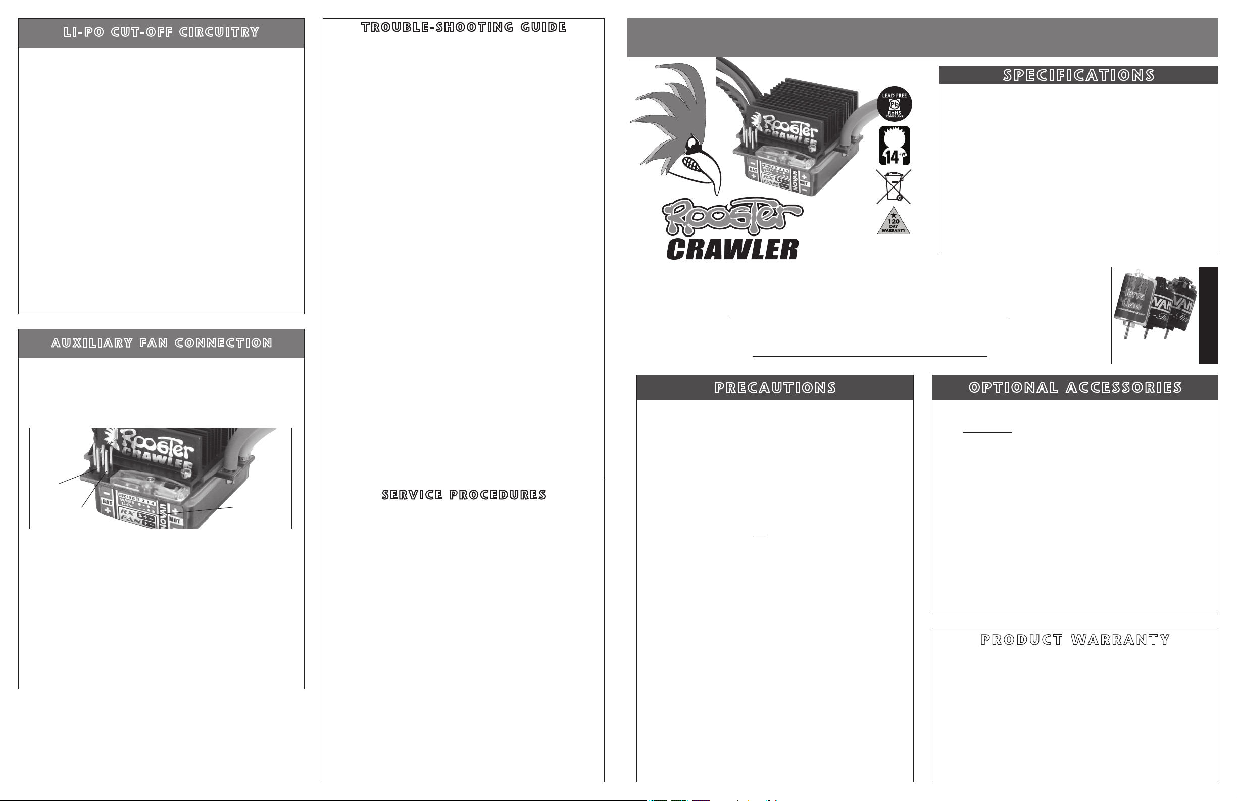
A U X I L I A R Y F A N C O N N E C T I O N
The Rooster Crawler ESC also features a set of power output pins for running
auxiliary cooling fans. This allows you to add cooling fans to either the motor,
the speed control, or both, and the best part is that they will automatically
switch off when you turn off the speed control’s power switch.
These pins output 6.0 volts DC (the same as the BEC), so you will get
maximum output from your cooling fans.
positive
fan pin
negative
fan pin
The Rooster’s pin-out label located on the front lower section of the ESC’s
case
(under the pins, push button, & LEDs)
ity of the fan power output pins. They are the 2 pins on the front edge of
the circuit board--Positive (+) is on the left, and Negative (–) is on the right.
The set of 3 pins behind them are for the user-replaceable input signal
harness, and the polarity of those is the same--Positive in the middle,
Negative on the right, and the extra pin on the left is signal.
The Novak 30x30x6mm clear cooling fan that comes on the GTB speed
control (Novak kit #5648) not only ts the size of the Rooster Crawler’s
heat sink perfectly, it also comes with the connector already on it for directly
plugging in. Fans that do not have the proper connector on them, will need
a connector
need to be soldered to the pins--Take extra care if attempting to solder to
the fan power output pins--Do not overheat the pins or the circuit board,
and do not allow any solder or wire strands to cause a short circuit with
other pins or the heat sink.
(one end of an old receiver input harness would work well)
shows the location and the polar-
pin-out label
, or will
NOVAK ELECTRONICS, INC.
ww w.t ea mn o va k. co m
(949) 833-8873 • FAX (949) 833-1631
Refer to Web site for service hours
and contact information
T R O U B L E - S H O O T I N G G U I D E
Steering Channel Works But Motor Will Not Run
• Red LED ashing: Speed control has thermally shut down––Allow ESC to
cool down––Use milder motor or smaller pinion gear––Check for adequate
cooling to ESC’s heat sink.
• Red & Green LEDs alternately ashing: Smart-Stop Li-Po circuitry has
shut off throttle output––Use a charged Li-Po battery. Using Ni-Cd or Ni-MH
batteries with ESC in Prole 2––change battery type or ESC Prole.
• Check motor connections. Check motor and brushes
• Make sure ESC is plugged into the throttle channel of receiver. Check
wiring color sequence of receiver signal harness (Refer to Step 1)
• Possible receiver damage––Check operation with a different receiver.
• Possible internal damage––Refer to Service Procedures.
.
.
Receiver Glitches/Throttle Stutters During Acceleration
• Receiver or antenna too close to ESC, power wires, battery, or motor.
• Bad connections––Check wiring, connectors, & sensor harness.
• Motor capacitors broken or missing––Refer to Step 3.
• Excessive current to motor––Use a milder motor or a smaller pinion gear.
• External Power Capacitor damaged/not installed––Replace Capacitor.
Untidy Wires
• Input harness and servo wires should be bundled separately. Power wires
should be as short as possible.
Motor and Steering Servo Do Not Work
• Check wires, receiver signal harness wiring & color sequence, radio
system, crystals, battery/motor connectors, & battery pack.
• Possible receiver damage––Check operation with a different receiver.
• Possible internal damage––Refer to Service Procedures.
Speed Control Runs Excessively Hot
• Gear ratio too low––Increase gear ratio
• If motor is damaged, try a different motor.
(smaller sized-pinion gear).
Model Runs Slowly/Slow Acceleration
• Check battery connectors––Replace if needed.
• Incorrect ESC/transmitter adjustment––Refer to Step 4 & Transmitter
Adjustments sections.
•
External Power Capacitor damaged/not installed––Replace Power Capacitor.
Motor Runs Backwards
• Motor wired backwards––Check wiring and reverse.
• Backwards motor timing––Reverse motor end bell.
ESC Is Melted Or Burnt/ESC Runs With Switch Off
• Internal damage––Refer to Service Procedures.
*For more assistance call our Customer Service Department or check our Web site.
S E R V I C E P R O C E D U R E S
Before sending in your ESC for service, please review the Trouble-Shooting
guide and instructions. Speed control may appear to have failed when
other problems exist.
After reviewing instructions, if you feel that your ESC requires service,
please obtain the most current product service options and pricing by the
following ways:
WEB SITE: Print a copy of the PRODUCT SERVICE FORM from the
CUSTOMER SERVICE section of the Novak Web site. Fill out the needed
information on this form and return it with the Novak product that requires
servicing.
PHONE/FAX: If you do not have access to the internet, please contact our
customer service department by phone or fax as listed below.
WARRANTY SERVICE: For warranty servi ce, you MUST CLAIM
WARRANTY on the PRODUCT SERVICE FORM and include a valid cash
register receipt with purchase date and dealer name & phone# on it, or an
invoice from previous service. If warranty provisions have been voided,
there will be service charges.
•ESCs returned without a serial number will not be serviced under warranty•
ADDITIONAL NOTES:
• Units that operate normally will have a service charge.
• Dealers/distributors are not authorized to replace Novak products thought
to be defective.
• If a hobby dealer returns your product for service, submit a completed
PRODUCT SERVICE FORM to the dealer and make sure it is included
with the product.
• Novak does not make any internal electronic components available for sale.
ROOSTER CRAWLER ESC – INSTRUCTIONS
S P E C I F I C AT I O N S
Input Voltage .....................4-7 cells
Li-Po Cut-Off Voltage .................................................6.25 volts DC
ESC Footprint .............................................
ESC Weight
(w/o wires)
.................................. 1.57 ounce
B.E.C. Rating ............................................. 6.0 volts DC / 5.0 amps
Power Wire
(Battery/Motor)
...........................14G Super-Flex Silicone
Rated Current .......................400A Fwd / 200A Rev
On-Resistance ............... 0.0014Ω Fwd / 0.0028Ω Rev
Motor Limit (single) .........................27 turn
Motor Limit (dual) ...........................35 turn
Throttle Profiles .................................................... 2
#55-1841-1 Ver. 2
4-2010
Switched Fan Output ...................................................6.0 volts DC
Attention crawler enthusiasts — The Rooster is ready to crawl!
The Rooster Crawler Brushed speed control has crawler-specific throttle profiles, and is specially designed with
built-in Smart-Stop Li-Po Cut-Off circuitry and a 6 volt / 5 amp BEC. The rugged ESC brings you 27-turn and
higher motor handling, high-drag brake and is also the ideal partner for Novak’s Crawler Brushed Motors.
The ESC also features Thermal Overload Protection, no Reverse Delay, Polar Drive & Digital Anti-Glitch circuitries for
cool & smooth operation and Radio Priority circuitry for the ultimate in control, right down to the end of the charge.
Add to this the user-replaceable power wires, power capacitor, & input harness, along with power output for auxiliary
cooling fans that turn on & off with the ESC’s power switch, and the Rooster Crawler-Edition has it all!
To benefit from all of the technical features of the Rooster Crawler, PLEASE READ ALL INSTRUCTIONS
P R E C A U T I O N S
DISCONNECT BATTERIES WHEN NOT IN USE
Always disconnect the battery pack from the speed control when not
in use to avoid short circuits and possible fire hazard.
27T SINGLE & 35T DUAL MOTOR LIMIT!
Do not use a single motor that is lower than 27-turns. For dual motors
for crawling, the motor range is 35 turns or above. A lower turn motor
may damage ESC.
WATER & ELECTRONICS DON’T MIX!
Never allow water, moisture, or other foreign materials to get inside ESC,
motor, or on the PC Boards. Water damage will void the warranty!
NO SCHOTTKY DIODE!
Schottky diodes must NOT be used with the Rooster Crawler ESC.
Schottky diode usage will damage ESC & void warranty!
4 TO 7 CELLS OR 2-CELL LI-PO ONLY
If using Ni-Cd or Ni-MH batteries, NEVER use fewer than 4 or more than
7 cells (4.8-8.4VDC, 1.2VDC/cell) in the vehicle’s main battery pack.
If using Li-Po batteries, ONLY use a 2-cell pack for the vehicle’s main
battery & be sure to use Profile 2 with the built-in Li-Po cut-off.
NO REVERSE VOLTAGE!
Reverse battery polarity can damage ESC & void warranty. Disconnect
battery immediately if a reverse connection occurs.
POWER CAPACITOR REQUIRED
An external power capacitor is installed and MUST be used with your
ESC. Failure to use Power Capacitor will result in higher ESC operating
temperatures & ESC damage.
TRANSMITTER ON FIRST
Always turn on the power of the transmitter first so that you will have
control of the vehicle when you turn it on.
INSULATE WIRES
Always insulate exposed wiring with heat shrink tubing or electrical tape
to prevent short circuits, which can damage ESC.
NO SOLVENTS
Exposing the ESC’s case to any type of solvents will damage the plastic.
NO CA GLUE
Exposure to CA glue or its fumes can cause damage to internal
components of the speed control and result in premature failure.
P1P4
O P T I O N A L A C C E S S O R I E S
REPLACEMENT POWER CAPACITOR
The Rooster Crawler-Edition ESC comes with a factory-installed Power Capacitor,
and it MUST BE USED to maintain cool and smooth operation. A direct replacement
Power Capacitor is available in Novak kit #5682.
Note: We highly recommend using Novak Power Capacitors, as we have done extensive testing & research
to find Power Capacitors with the very best quality factors––other capacitors with similar ratings will not
provide equal protection.
SUPER-FLEX SILICONE 14G WIRE
Novak Super-Flex wire for power wiring. 14 gauge silicone wire in kit #5514
(36”black, 36”red, & 36”blue).
INPUT SIGNAL HARNESS
User-replaceable input signal harness is available in both short and long lengths.
4.5” harness in Novak kit#5315, and 9.0” harness in Novak kit #5320.
MOTOR CAPACITORS
Additional motor capacitors are available in Novak kit #5620.
AUXILIARY COOLING FANS
The Rooster Crawler comes with power output pins ready to add a cooling fan
that will switch on & off with the ESC’s power switch.
Novak 25x25x10mm fan with long leads for cooling motor is available in Novak kit
#5647. Novak 30x30x6mm clear fan that fits perfect over the ESC’s heat sink and
has a connector already on its leads is available in Novak kit #5648.
The Rooster Crawler ESC is guaranteed to be free from defects in materials or workmanship for a period of 120 days from
the original date of purchase (verified by dated, itemized sales receipt). Warranty does not cover incorrect installation,
components worn by use, damage to case or exposed circuit boards, damage from using fewer than 4 or more than 7
Ni-Cd or Ni-MH cells (1.2 volts DC/cell) or fewer or more than 2 Li-Po cells input voltage, cross-connection of battery/
motor power wires, overheating solder tabs, reverse voltage application, damage resulting from thermal overload
from incorrect installation of FET servo or receiver battery pack, not using or incorrect installation of a Power Capacitor on
ESC or from using a damaged Power Capacitor, using a Schottky diode, using non-Novak Power Capacitor, splices to input
or ON/OFF switch harnesses, damage from excessive force when using the One-Touch/SET button or from disassembling
case, tampering with internal electronics, allowing water, moisture, or any other foreign material to enter ESC or get
onto the PC board, incorrect installation/wiring of motor/battery connectors, input plug plastic, or auxiliary cooling fan,
allowing exposed wiring, pins, or solder tabs to short-circuit, or any damage caused by a crash, flooding or natural disaster.
Because Novak Electronics, Inc. has no control over the connection & use of the speed control or other related
electronics, no liability may be assumed nor will be accepted for any damage resulting from the use of this product,
including battery packs. Every Novak speed control & motor is thoroughly tested & cycled before leaving our
facility and is, therefore, considered operational. By the act of connecting/operating speed control, user accepts
all resulting liability. In no case shall our liability exceed the product’s original cost. We reserve the right to modify
warranty provisions without notice.
©2010 Novak Electronics, Inc. • All Rights Reserved
ten permission of Novak Electronics, Inc. • Rooster
& One-Touch Set-Up are all trademarks of Novak Electronics, Inc. • All Novak speed controls are designed &
assembled in Irvine, CA, and are Lead-Free & RoHS compliant.
P R O D U C T WA R R A N T Y
• No part of these instructions may be reproduced without the writ-
(@1.2 volts DC/cell)
/ 2 Li-Po cells
1.18” x 1.54” [30x39mm]
[44.5 grams]
@25°C trans.temp.
@25°C trans.temp.
[@ 6 cells Ni-MH(1.2VDC/cell)]
[@ 6 cells Ni-MH(1.2VDC/cell)]
[1 with Li-Po Cut-Off]
Terra Claw Crawling (#3556)
Forty-Five Crawler (#3545)
Fifty-Five Crawler (#3555)
[Novak kit #5682]
[Novak kit #5514]
[Novak kits #5315 & 5320]
[Novak kit #5620]
[Novak kits #5647 & #5648]
Crawler ESC, Polar Drive Technology, Radio Priority Circuitry,
motors for Rooster Crawler
Recommended brushed
, damage

S T E P 1 – C O N N E C T I N P U T H A R N E S S
S T E P 3 – M O T O R & B AT T E R Y C O N N E C T I O N
S T E P 4 – O N E - T O U C H P R O G R A M M I N G
The Rooster Crawler Brushed ESC has the industry-standard receiver input
connector
radio brand’s new receivers. However, some very old receivers must have
the wiring
important, because receiver & servo electronics may be damaged if the
sequence is incorrect.
on a
user-replaceable input harness & works with all major
sequence in the plastic 3-pin connector housing changed.
This is
C H A N G I N G W I R I N G S E Q U E N C E @ R E C E I V E R E ND
JR • Hitec • Futaba • New KO • Airtronics Z
JR, Hitec, Futaba, new KO, & Airtronics Z receivers do not need input harness re-wiring. Airtronics Z receivers have blue plastic cases & new
cases have tabs on the input harness openings as in Figure 1.
Plug one end of the input signal harness into the THROTTLE CHANNEL (#2) of
•
receiver with the BLACK wire toward the outside edge of receiver case.
• Plug the other end of the input harness into 3-pin header on the front edge
of the
ESC
ESC (refer to pin-out label on case).
’s circuit board with the WHITE wire toward the left side of the
KO
New KO (with tabs) Old KO (no tabs)
tabs
white
red
black
FIGURE 1
no tabs
white
black
red
FIGURE 2
Old-style KO • Old-style Sanwa/Airtronics
If you have an older KO or Sanwa/Airtronics, you must change the sequence
of the ESC’s input harness wires--Old Sanwa/Airtronics cases
& Old KO cases do not have tab openings, as in Figure 2 above.
•
Using a small at blade screwdriver, remove the red & black wires from the
plastic housing at the receiver end of the input harness as in Figure 3 below.
• Interchange the red and black wires in the plastic 3-pin connector housing
at the receiver end of the input harness.
• Insert modied end of the harness into the THROTTLE CHANNEL (#2) of
receiver with the RED wire toward the outside edge of receiver case.
• Plug the other end of the input harness into the
toward the ‘S’ (signal) marking on the ESC’s case.
FIGURE 3 With a small standard screwdriver, gently lift plastic prong
until wire and metal socket easily slide out of plastic housing.
ESC
are black color
with the WHITE wire
1. INSTALL MOTOR CAPACITORS
Electric motors generate RF noise that causes interference.
0.1µF (50V) non-polarized, ceramic capacitors
to reduce motor noise & prevent ESC damage. Novak’s Crawler Brushed
Motors (#3545 & #3555) have the required capacitor’s factory installed.
Note:
has two capacitors, you need to install a capacitor between
& negative motor tabs––If you experience radio inter
Some motors come with capacitors built-in. If your motor only
only built-in capacitors, install external ones.
must be
Solder 0.1µF (50V) capacitors between:
• POSITIVE (+) motor tab & NEGATIVE (–) motor tab.
• POSITIVE (+) motor tab & GROUND tab*.
• NEGATIVE (–) motor tab & GROUND tab*.
*If motor has no ground tab (below), solder the capacitors to motor can.
Negative (-) motor tab
**NO SCHOTTKY DIODE**
0.1µF Capacitors
FIGURE 4
Extra 0.1µF capacitors are available in Novak kit #5620.
Positive (+) motor tab
Ground / motor can
The included
used on all motors
the positive
ference when using
2. DO NOT USE SCHOTTKY DIODES
Schottky diodes must NOT be used with reversible ESCs (including
brushless). Schottky diode usage will damage the ESC & void warranty.
Red power wire
(battery positive)
Black power wire
(battery negative)
3. FACTORY-INSTALLED POWER CAPACITOR REQUIRED
The ESC comes with a factory-installed Power Capacitor, and it MUST be
used for proper operation and protection.
I
f Power Cap. becomes dented or damaged, ESC failure will occur--replace
immediately (#5682). Longer Power Capacitor wires will decrease performance.
4. SOLDER MOTOR POWER WIRES TO MOTOR
a.
Cut the ESC’s BLUE & YELLOW silicone motor power wires to the desired
length, and strip 1/8-1/4” of insulation from the end of each wire. Tightly
twist the exposed strands of wire. Tin the wire ends with solder.
b.
Solder the ESC’s BLUE motor wire to the motor’s negative (–) tab.
c.
Solder the ESC’s YELLOW motor wire to the motor’s positive (+) tab.
5. CONNECT SPEED CONTROL TO BATTERY PACK
Connect the ESC’s Tamiya-style JST battery connector to a charged 4 to
7 cell (1.2VDC/cell) battery pack (or 2-cell Li-Po pack). The connector can
also be changed to a different type, or the ESC can be hard-soldered directly
to the battery pack.
C O N N E C T O R U S A G E
If you are going to use connectors on the ESC’s motor wires, we highly
suggest Dean’s Ultra plugs or Novak’s low-loss connectors--do not use
crimp type connectors.
aware that this can void the warranty if not done properly.
To prevent possible cross-connection of motor and battery wires:
• Use connectors that cannot be plugged in backwards. Reverse voltage
will damage the ESC and void warranty.
• Use a female connector on battery packs to avoid shorting.
For additional information on Novak connectors & their usage, visit our Web site.
Trail excess wire off top
of antenna mast
Tamiya-style
battery connector
Note: If you plan to change the battery connector, be
Battery Pack
NiMH: 4 to 7 cell pack
Li-Po: 2S pack*
(+)
*If using Li-Po
batteries, be sure
to select Throttle
Prole 2 so that
Li-Po Cut-Off
Circuitry is enabled.
With ESC connected to (at least) a receiver & a charged battery pack:
1. TURN ON THE TRANSMITTER’S POWER
2. PRESS & HOLD ESC’S ONE-TOUCH/SET BUTTON
3. TURN ON THE SPEED CONTROL’S POWER
With transmitter throttle at neutral, and still pressing the SET button,
slide the ESC’s ON/OFF switch to ON position.
4.
CONTINUE HOLDING SET BUTTON UNTIL RED LED COMES ON
5. RELEASE SET BUTTON AS SOON AS LED TURNS RED
6.
PULL TRANSMITTER THROTTLE TO FULL-ON POSITION
Hold it there until the green status LED turns solid green.
Note: Motor will not run during programming even if connected.
7. PUSH TRANSMITTER THROTTLE TO FULL-BRAKES
Hold it there until the green status LED blinks green.
8. RETURN TRANSMITTER THROTTLE TO NEUTRAL
Red status LED will turn solid red, indicating that speed control is at
neutral and that proper programming has been completed.
NOTE: If transmitter settings are changed, One-Touch Programming must be
repeated. If you experience any problems, turn off ESC & repeat One-Touch.
REMEMBER: Whenever One-Touch set-up is performed,
ESC automatically reverts to Throttle Prole #1.
T R A N S M I T T E R A D j U S T M E N T S
•NOT ALL TRANSMITTERS HAVE THESE ADJUSTMENTS•
If you have any problems with Step 4, adjust transmitter as follows and then
repeat One-Touch programming in Step 4:
A. Set HIGH ATV or EPA to maximum setting.
[amount of throw at full throttle]
B. Set LOW ATV, EPA, or ATL to maximum setting.
[amount of throw at full brakes]
C. Set EXPONENTIAL to zero setting. [throttle channel linearity]
Set THROTTLE CHANNEL REV. SWITCH to opposite position.
D.
E. Set THROTTLE CHANNEL TRIM to middle setting.
[adjusts neutral position/increases or decreases coast brakes]
F.
Set ELECTRONIC TRIGGER THROW ADJUSTMENT to 50%
and 50% brake throw--best for reversible ESCs.
[adjusts trigger throw electronic/digital pistol-grip transmitters]
G.
Set MECHANICAL TRIGGER THROW ADJUSTMENT to position
1/2 throttle and 1/2 brake throw.
throttle
with
S T E P 2 – M O U N T I N G E S C
Be sure to position the ESC with the power wires away from other electronics
& moving parts in the vehicle. Select a location that allows airow through
heat sinks--If the ESC gets good air ow, it will run cooler; and that
means it will be more efcient!
1. MOUNT ESC IN THE VEHICLE using the included double-sided tape.
Be sure receiver & antenna are mounted as far from ESC, power
wires, battery, & servo as possible--these components all emit RF
noise when throttle is applied. On graphite or aluminum chassis
vehicles, it may help to place receiver on edge with crystal & antenna
as far above chassis as possible.
Note: Mount antenna as close to receiver as possible--trail any excess wire off top
of antenna mast (cutting or coiling excess antenna wire will reduce radio range).
2. MOUNT POWER CAPACITOR IN THE VEHICLE using the included
double-sided tape, or secure it to part of the vehicle with a tie-wrap. The
Power Capacitor can also be tie-wrapped along the battery power wires.
If the Power Capacitor becomes dented or damaged, ESC failure
will occur--replace damaged Power Capacitors immediately.
3. INSTALL ON/OFF SWITCH using a screw or the included double-sided
tape. Position in the vehicle where it will be easy to access.
Power Capacitor
tie-wrapped
along power wires
Servo
plugged
into
steering
ch. (#1)
User-replaceable input
signal harness (Ch.2)
R O O S T E R C R A W L E R S E T- U P P H O T O
U S I N G A R E C E I V E R B AT T E R Y P A C K
The Rooster Crawler has a built-in BEC (battery eliminator circuit), and you
do not need to use a separate receiver battery pack, however if you are
planning to use one to power the electronics you need to do the following:
1. Plug the external 5 cell (1.2VDC/cell) receiver battery pack into the battery
slot of the receiver.
2. Leave the ESC’s ON/OFF switch in the OFF position, and use receiver
battery pack’s ON/OFF switch to turn the system power on and
P2
off––Do not use the ESC’s switch.
Rooster
Crawler ESC
Status LEDs
(–)
ON/OFF
switch
One-Touch
Set-Up
button
Yellow power wire
(motor positive)
Blue power wire
(motor negative)
Novak #3555 Fifty-Five
Crawler Brushed
Motor Shown
27-turn or higher
brush-type motor
w w w . t e a m n o v a k . c o m
T H R O T T L E P R O F I L E S E L E C T I O N
The Rooster Crawler is equipped with 2 user-selectable Throttle Proles
Parameter PROFILE 1 PROFILE 2
Li-Po Cut-Off
W/ Reverse Yes (100%) Yes (100%)
Drag Brake 90% 90%
SELECTING THROTTLE PROFILE:
With ESC on & connected to a charged battery (transmitter ON or OFF):
1. IF TRANSMITTER IS OFF, DISCONNECT ESC FROM RECEIVER
To avoid possible radio interference from other transmitters, remove the
ESC’s input signal harness from the receiver.
2. PRESS & HOLD THE ESC’S ONE-TOUCH SET BUTTON
Continue to hold SET button on ESC until both LEDs turn on.
3. RELEASE SET BUTTON AS SOON AS BOTH LEDs COME ON
Once released, the 2 status LEDs will ash to indicate what Throttle
Prole is currently selected. The number of times the LEDs ash
indicates the Throttle Prole selection (1 of 2).
4. QUICK PRESS
Each press will change to the next consecutive Throttle Prole.
*** Note: there is a time constraint during this selection process. ***
5. ESC STORES SELECTION & EXITS TO NEUTRAL
If SET button is not pressed for 3 sec., ESC stores selected Prole into memory
& the red LED will come on solid. The speed control is at neutral & is ready to go.
NOTE: Whenever One-Touch set-up is performed, ESC reverts to Throttle Prole #1.
P3
(see next page) Disabled Enabled
NOTE: ESC is factory set to Throttle Prole #1.
(& release)
SET BUTTON TO CHANGE SELECTION
:
 Loading...