

Page 1
E-MAXX COMBO
Part #1855
++
OPERATING INSTRUCTIONS
ROOSTER E-Maxx COMBO
The ROOSTERS are the long standing benchmark in reliable
reversible speed controls for 6-7cell/mild-modified set-ups.
With two Roosters installed in your Traxxas E-Maxx using
the included Input Signal Y-Harness, the Rooster E-Maxx
Combo lets you hop-up your E-Maxx with the ability to
run standard 7.2V
motors not recommended)
brakes before the engagement of reverse, and the Roosters
feature Novak’s Smart Braking CircuitryTM that brings
the model to a slow speed before hitting reverse to save
your vehicle’s gearbox and reduce speed control heating.
These speed controls feature the original One-T ouch Set-Up
(There’s nothing easier!), exclusive Polar Drive T echnology
for the smoothest throttle response and improved radio
system performance, and Reverse Disable
that locks-out reverse for racing or forward only use.
Other features include built-in brake light circuitry to
power two high-intensity LEDs for enhanced realism
(available separately in the Novak Brake Light LED Kit
#5655), Radio Priority Circuitry
control even after the battery has discharged, and dual-
level thermal protection.
(05 & 075 size) motors (stock Traxxas
. You also get the added benefit of
TM
Circuitry
TM
to maintain steering
TM
SPECIFICATIONS
Input Voltage (1.2VDC/cell) 6-7 cells
Case Width 1.63 inches
Case Depth 2.02 inches
Case Height (w/h.sinks) 1.22 inches
Weight (w/heat sinks) 3.00 ounces
On-Resist.–Fwd. (@Trans) 0.018 Ω
On-Resist.–Rev. (@Trans) 0.018 Ω
Rated Current–Fwd. 100 amps
Rated Current–Rev. 100 amps
Braking Current 100 amps
Rev. Delay (after Smart Braking) Zero Sec.
BEC Voltage 5.0 volts DC
BEC Current 1.0 amp
Power Wire 16G / 6”
Signal Harness 26G / 6”
Transistor Type MEGAFET
PWM Frequency 1250 Hertz
Motor Limit Mild Modified*
Part Number 1855
*14 turn motors with available Traxxas E-Maxx gear ratios
QUICK SET-UP
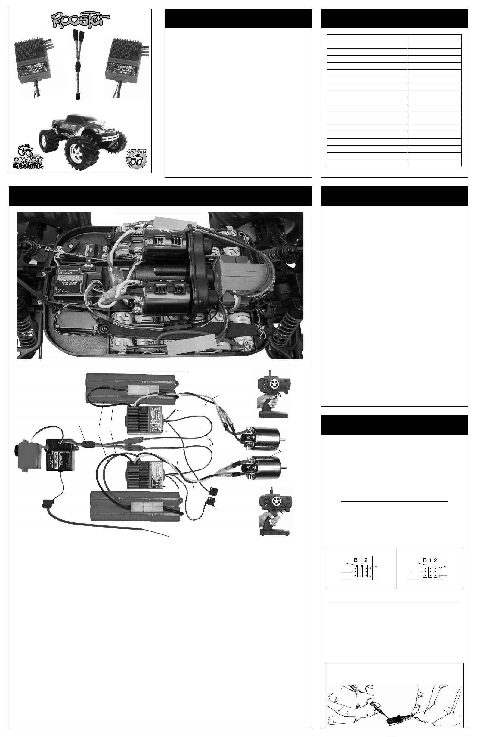
E-MAXX INSTALLATION PHOTO
CONNECTION PHOTO
6-7 Cell Battery Pack
C.
Y-Harness
B.
A. INSTALL SPEED CONTROLS
Use double-sided tape to mount ESCs in the rear tub of
E-Maxx.
For more details refer to Step 2.
B. CONNECT SPEED CONTROLS TO RECEIVER
Plug input signal harnesses of each ESC into the double
side of the Y-Harness. Plug single side of the Y-Harness
into the throttle channel
E-Maxx receiver, make sure ESC signal harness has
proper wiring sequence.
of receiver. If not using stock
Refer to Step 1 to change wiring.
C. CONNECT SPEED CONTROLS TO BATTERIES
Plug the JST/Tamiya connector from the first ESC into
one of the battery packs (6-7 cell @ 1.2 volts DC/cell).
Plug the second ESC into the other battery pack.
We found that connecting the left side ESC to the right side
motor & battery in the truck keeps excess wire to a minimum,
and you won’t have to tie wrap the wires to keep them
inside the truck and away from moving parts.
D.TURN ON TRANSMITTER POWER
Refer to Step 5 for transmitter adjustments.
E. TURN ON SPEED CONTROLS
Slide ON/OFF switches to the ON positions.
F.
PRESS AND HOLD ESC 1’s ONE-TOUCH BUTTON
With the transmitter throttle in neutral position, press
and hold the One-Touch button on the first speed control
until the status LED turns solid red, then release.
G.
PULL THROTTLE TO FULL-FORWARD POSITION
Hold until status LED turns solid green.
H.PUSH THROTTLE TO FULL-REVERSE POSITION
Hold until status LED blinks green, then return throttle
to neutral position. LED will then turn solid red indicating
proper programming and throttle is in neutral position.
red
wires
black
wires
6-7 Cell Battery Pack
C.
FOR DETAILED INFO. REFER TO STEPS 1 THRU 6
A.
(+)
(-)
twist motor
wires to reduce
RF noise
brake
wires
light
blue
wire
yellow
wire
G/J.
L.
(+)
I.
input
signal
blue
wire
F.
(+)
(-)
wire off top of
antenna mast
I.
J.
yellow
wire
trail excess
PRESS AND HOLD ESC 2’s ONE-TOUCH BUTTON
With the transmitter throttle in neutral position, press
and hold the One-Touch button on the second ESC
until the status LED turns solid red, then release.
PULL THROTTLE TO FULL-FORWARD POSITION
Hold until status LED turns solid green.
harnass
E.
ON/OFF
switches
(-)
(+)
L.
(-)
three 0.1µF
capacitors
•NO SCHOTTKY•
H/K.
K. PUSH THROTTLE TO FULL-REVERSE POSITION
Hold until status LED blinks green, then return throttle
to neutral position. LED will then turn solid red indicating
proper programming and throttle is in neutral position.
L. CONNECT SPEED CONTROLS TO THE MOTORS
Use 7.2V (05 or 075 size) standard R/C motors
with 14 turns** or higher in the Traxxas E-Maxx.
Turn off speed controls then transmitter.
Plug the bullet connector on the YELLOW wire of the
first speed control to positive of the first motor.
Plug the bullet connector on the BLUE wire of the first
speed control
Plug the bullet connector on the YELLOW wire of the
second speed control to positive of the second motor.
Plug the bullet connector on the BLUE wire of the second
speed control to negative of the second motor.
Again, we found that connecting the left side ESC to the
right side motor & battery in the truck works best.
M
.KICK-UP A ROOST!
Turn on transmitter and then the speed controls.
**Rooster motor specification is 16 turns or higher (mild modified).
14 turns can be used with E-Maxx using available Traxxas gear ratios.
to negative of the first motor.
PRECAUTIONS
•
WATER & ELECTRONICS DON’T MIX!
operate model in or around water. Never allow water,
moisture, or other foreign materials to get inside the ESC.
• USE NEUTRALLY TIMED MOTORS Using motors with
other than 0° timing will draw excess current in reverse,
and result in ESC overheating and premature motor wear.
Modified motors
Johnson/Mabuchi
• 6 or 7 CELLS ONLY Never use fewer than 6 or more than
7 cells (7.2-8.4 volts DC) in each main battery pack.
•
MOTOR CAPACITORS REQUIRED Three 0.1µF (50V)
ceramic capacitors (included) must be properly installed
on every motor to prevent radio interference.
• ALWAYS USE HEAT SINKS Four heat sinks are factoryinstalled on each Rooster, and must be used for maximum
cooling and performance.
• NO REVERSE VOLTAGE!
damage speed control––Disconnect battery immediately.
• NO SCHOTTKY DIODES External Schottky diodes must
NOT be used with reversible speed controls. Using an
external Schottky diode will damage the ESC.
DON’T LET TRANSISTOR TABS TOUCH Never allow
•
separate transistor banks to touch each other or any exposed
metal. This will create a short circuit and damage the ESC.
• DISCONNECT THE BATTERIES Always disconnect the
battery pack from the speed control when not in use.
• TRANSMITTER ON FIRST
the ESCs so you will have control of the radio equipment.
• DON’T GET BURNT
can get extremely hot, so be careful not to touch them
until they cool. Supply adequate air flow for cooling.
• INSULATE WIRES Always insulate exposed wiring with
heat shrink tubing to prevent short circuits.
(with adjustable end bells) timed to 0° or
(closed end bell) motors are recommended
Reverse battery polarity can
T urn on your transmitter before
! Transistor tabs and the heat sinks
Do not
STEP 1
CHANGING THE INPUT HARNESS
The Rooster speed controls come with the industry standard
input
harness connector. This connector works
major radio brands. However, with some older style
receivers the sequence of the wires in the plastic connector
housing needs to be changed. This is an important step,
because the electronics inside the receiver may be damaged
if the wiring sequence is incorrect. Changing the wiring is
easily accomplished as described below.
JR • Hitec • New KO • Airtronics Z
If your receiver is a JR, Hitec, Futaba, new KO, or an
Airtronics Z (blue case) you do not need to change the
sequence of
have tabs on the input harness openings as in Figure 1.
• Insert the input plug into the receiver with the BLACK
wire toward the outside edge of the receiver case.
tabs
red
wires
the ESC's input harness wires.
FIGURE 1 FIGURE 2
white
wires
black
New KO (with tabs) Old KO (no tabs)
wires
no tabs
black
wires
Old-style KO • Old-style Sanwa/Airtronics
If your receiver is an older KO or Sanwa/Airtronics, you
must change the sequence of the ESC's input harness
wires. Old Sanwa/Airtronics cases are black in color. Old
KO cases do not have the tab openings (See Figure 2).
• Interchange the red and black wires in the plug plastic
of the ESC's input harness as shown in Figure 3 below.
• Insert the input plug into the receiver with the RED wire
toward the outside edge of the receiver case.
FIGURE 3 With a small standard screwdriver, gently lift
the plastic prong until the wire and metal socket easily
slides out of the plastic housing. Repeat for each wire.
with all
New KO cases
white
wires
red
wires
Page 2
STEP 2
MOUNTING INSTRUCTIONS
1. INSTALL SPEED CONTROL
The two Rooster speed controls should be positioned
back to back and mounted on their sides in the rear
electronics area of the E-Maxx as shown in the E-MAXX
Installation
sided
chassis.
Note: Heat sinks are required with Rooster ESCs for optimum
performance and power handling. The Rooster heat sinks
come factory installed and must not be removed.
DO NOT SHORT CIRCUIT HEAT SINKS The three banks of
transistor tabs are separated by plastic on the case top. Each
bank of heat sinks should never contact each other or other
conductive objects (metal, etc.),
damage the speed control.
Replacement Rooster heat sinks available in Novak kit #5409.
2. INSTALL ON/OFF SWITCHES
Determine a convenient place to mount the switches
where they will be easy to get to. Mount the switches
using double-sided tape or with screws through the
hole in the base of the switch housings.
In our install, we mounted the switches to the E-Maxx’s
stock switch holes with the screws that held in the E-Maxx
switch. In this location, just ahead of the left rear tire, the
switches are easy to get to without removing the body.
3. RECEIVER NOTES
If you are not using the stock E-Maxx receiver, be sure
to mount the receiver as far from the motor, power
wires, battery, and servo as possible
These components all emit radio noise when the throttle
is being applied. Mount the antenna close to the receiver
and trail any excess wire off the top of the antenna.
photo on front. Use the included double-
tape to mount the speed controls to the truck’s
or they will short circuit and
(stock position works well)
STEP 3
HOOK-UP INSTRUCTIONS
Refer to Quick Set-Up Installation & Connection Photos on front
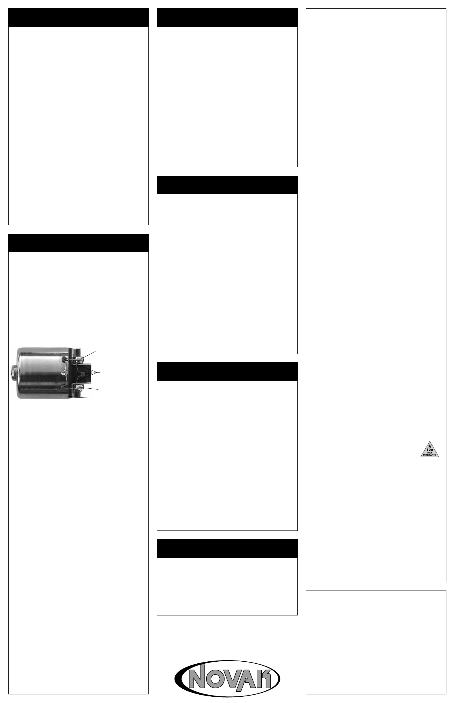
1. INSTALL MOTOR CAPACITORS
Electric motors generate radio noise that can interfere
with your receiver and cause radio problems. Included
in the ESC accessory kit are six 0.1µF (50V) nonpolarized, ceramic capacitors. Three capacitors must
be installed on each motor to help reduce the noise
generated by the motor and to prevent ESC damage.
Solder 0.1µF (50V) capacitors between:
• POSITIVE (+) motor tab & NEGATIVE (
• POSITIVE (+) motor tab & GROUND tab*.
• NEGATIVE (
*If your motor does not have a ground tab, solder the capacitor
leads to the can of the motor as shown below.
-) motor tab & GROUND tab*.
Ground / motor can
Extra 0.1µF capacitors are available in Novak kit #5620
2. IMPORTANT NOTE ABOUT SCHOTTKY DIODES
NO SCHOTTKY DIODES
Schottky diodes must NOT be used with reversible
speed controls. Using a Schottky diode will damage
the speed control and will void the warranty.
3. CONNECT SPEED CONTROLS TO THE Y-HARNESS
After the proper wiring sequence has been configured
to match the receiver (Refer to Step 1), plug the input
signal harnesses from both speed
double end of the included
The brown wire on the Y-Harness is the negative (-) wire
and should connect to the black wire of the ESC.
4. CONNECT Y-HARNESS TO THE RECEIVER
Plug the single end of the
THROTTLE CHANNEL of the receiver.
CONNECT SPEED CONTROLS TO THE BA TTERY P ACKS
4.
Plug the JST/Tamiya connector from the first ESC into
one of the battery packs
Plug the second ESC into the other battery pack.
We found that connecting the left side ESC to the right
side motor & battery in the truck keeps excess wire to a
minimum, and you won’t have to tie wrap the wires to
keep them inside the truck and away from moving parts.
*Removal of JST/Tamiya connector voids warranty.
5. CONNECT SPEED CONTROLS TO THE MOTORS
Plug the bullet connector on the YELLOW wire of the
first speed control to positive of the first motor.
Plug the bullet connector on the BLUE wire of the first
speed control
to negative of the first motor.
Plug the bullet connector on the YELLOW wire of the
speed control to positive of the second motor.
second
Plug the bullet connector on the BLUE wire of the
second speed control to negative of the second motor.
Again, we found that connecting the left side ESC to the
right side motor & battery in the truck works best.
TIP: Twist BLUE & YELLOW motor wires once or twice as they go to
the motor to reduce any radio noise emitted from power wires.
MOTOR SELECTION:
mum performance. Typical motors are not tuned to operate in
reverse, and draw excessive current that can cause ESC overheating. Modified motors timed to 0
(closed end like E-Maxx stock motor) motors are recommended.
Ask a hobby dealer to help select a properly timed motor.
Use neutrally timed (0°) motors for opti-
Y-HARNESS
Y-HARNESS into the
(6-7 cell @ 1.2 volts DC/cell).
°
-) motor tab.
Negative (-) motor tab
0.1µF Capacitors
Positive (+) motor tab
controls into the
.
or Johnson/Mabuchi
STEP 4
TRANSMITTER ADJUSTMENTS
For proper speed control operation and programming
set transmitter adjustments as follows:
1. Set HIGH ATV or EPA to maximum setting.
[Amount of throw at full throttle]
2. Set LOW ATV, EPA, or ATL to maximum setting.
[Amount of throw at full brakes]
3. Set EXPONENTIAL to zero setting.
[Throttle channel linearity]
4. Set THROTTLE CHANNEL TRIM to middle setting.
[Adjusts neutral position/Increases or decreases coast brakes]
5.
Set THROTTLE CHANNEL REVERSING SWITCH to
either position.
[Do not change switch position after programming]
6. Set ELECTRONIC TRIGGER THROW ADJUSTMENT to
50% throttle and 50% brake throw (or 5:5).
[Adjusts pistol-grip transmitter’s throttle trigger throw on
electronic/digital transmitters]
7. Set MECHANICAL TRIGGER THROW ADJUSTMENT
to position with 1/2 throttle and 1/2 brake throw.
[Adjusts pistol-grip transmitter’s throttle trigger throw on
mechanical/analog transmitters]
TROUBLE-SHOOTING GUIDE
This section describes possible speed control problems,
causes, and solutions.
Steering Channel Works But Motor W ill Not Run
• Speed control has thermally shut down––Allow ESCs to
cool down––Use milder motors or smaller pinion gears.
• Check motor connections. Check motors and brushes.
• One motor wired backwards––Check wiring and reverse.
•
Make sure ESCs are plugged into Y-Harness and Y -Harness
plugged into throttle channel of
channel operation with a servo. Check wiring color
sequence of receiver signal harness.
• Possible internal damage––Refer to Service Procedures.
Receiver Glitches/Throttle Stutters During Acceleration
• Motor capacitors broken or missing––Refer to Step 3.
• Receiver or antenna too close to speed controls, power
wires, batteries, or motors––Refer to Step 2.
• Bad connections––Check wiring and connectors.
• Motor brushes worn––Replace brushes.
• Excessive current to motors––Use milder motors or smaller
pinion gears.
Motor and Steering Servo Do Not Work
•
Check wires, receiver input signal harness wiring and
sequence, radio system, crystals, battery and
color
motor
connectors, and battery packs.
• Possible internal damage––Refer to Service Procedures.
receiver. Check throttle
Model Runs Slowly / Slow Acceleration
STEP 5
SPEED CONTROL PROGRAMMING
.
Both ESCs should be connected to the Y -Harness, Y-Harness
connected to the receiver, both ESCs
connected to charged
battery packs, and the transmitter adjusted as in Step 4.
1. DISCONNECT MOTORS
2. TURN ON THE TRANSMITTER
TURN ON THE FIRST SPEED CONTROL
3.
(2nd will come on)
4. PRESS AND HOLD ESC’s ONE-TOUCH BUTTON
With transmitter throttle at neutral, press and hold
ESC’s
One-Touch
button until status
LED
turns solid r ed.
5. RELEASE ESC SET BUTTON WHEN LED IS RED
PULL TRANSMITTER THROTTLE TO FULL-ON POSITION
6.
Hold it there until the status LED turns solid green.
NOTE: The motor will not run during programming even if it
is connected to the speed control.
7. PUSH TRANSMITTER THROTTLE TO FULL-REVERSE
Hold it there until the status
LED blinks green.
8. RETURN TRANSMITTER THROTTLE TO NEUTRAL
Status
LED
will turn solid red, indicating that throttle is
at neutral and proper programming has been completed.
9. REPEAT STEPS 2-7 WITH SECOND ESC
10.
CONNECT MOTORS
Speed controls are programmed & r eady to kick-up a roost!
If transmitter settings are changed, it will be necessary to complete
the programming sequence once again. If you experience problems
during programming, turn off speed control and repeat programming.
STEP 6
REVERSE DISABLE PROGRAMMING
Both speed controls should be connected to the Y -Harness,
the Y -Harness connected to the receiver, both speed controls
connected to charged battery packs, and the transmitter
should be adjusted according to Step 4.
1. TURN ON THE TRANSMITTER
2. TURN ON THE FIRST SPEED CONTROL
3. PRESS AND HOLD ESC’s ONE-TOUCH BUTTON
Press and hold the ESC
status LED turns from solid red to solid green.
RELEASE ONE-TOUCH BUTTON WHEN LED IS GREEN
4.
5. PRESS ONE-TOUCH BUTTON TO ENABLE/DISABLE
SLOW RED FLASH = REVERSE ENABLED
FAST RED FLASH = REVERSE DISABLED
Note: You must press the One-Touch button very soon after
the LED begins flashing red (slow or fast).
6. LED WILL TURN GREEN THEN EXIT PROGRAMMING
Green LED indicates ESC is exiting programming mode.
7. REPEAT STEPS 2-6 WITH SECOND ESC
Note: Both speed controls must have reverse enabled or
disabled.
the motors will fight each other when the one ESC tries to go
into reverse and the other stays in the braking mode. This
could draw excess current and overheat the ESCs.
If one ESC has reverse enabled and one disabled,
BRAKE LIGHTS
The Rooster speed controls are equipped with Brake Light
Cicuitry that allows you to power two high-intensity LEDs
for realistic model brake lights. The brake lights get their
power from the small red and black 26G wires that exit
the front of the speed control’s case along with the input
signal harness and ON/OFF switch. The optional Brake
Light LED Kit (#5655) includes two LEDs, wire harness,
brake light mounting brackets, and detailed instructions.
One-Touch button until the
•
Check motor and battery connectors––Replace if needed.
•
Reverse not disabled/enabled in both ESCs––Refer to Step 6.
• Bad battery or motor––Check operation with another .
Incorrect transmitter/ESC adjustment––Refer to Step 4 & 5.
•
• Using stock Traxxas 14.4V motors––Use 7.2V motors.
Motor Runs Backwards
• Both motors wired backwards––Check wiring and reverse.
• Backwards motor timing––Reverse motor end bell.
ESC Is Melted Or Burnt/ESC Runs With Switch Off
• Internal damage––Refer to Service Procedures.
*For more help visit our website or contact Customer Service.
SERVICE PROCEDURES
Before sending your Rooster ESCs for service, review
T rouble-Shooting guide and the instructions. The ESCs may
appear to have failed when other problems exist.
After reviewing the instructions, if you feel that one of your
ESCs require service, please obtain the most current product
service options and pricing by one of the following methods:
WEBSITE: We have an abundance of information available
for all levels of speed controls, and all of our products. Print
a copy of the PRODUCT SERVICE FORM from the SERVICE
section of the website. Fill out the needed information on
this form and return it with the Novak product that requires servicing.
PHONE/FAX/E-MAIL: If you do not have access to the
internet, contact our customer service department by
phone, fax, or e-mail as listed in the CUSTOMER SERVICE
section below, and they will supply you with current service
options and send you a PRODUCT SERVICE FORM.
WARRANTY SERVICE:
WARRANTY on the PRODUCT SERVICE FORM and include a
valid cash register receipt with purchase date on it, or an
invoice from previous service work. If warranty provisions
have been voided there will be service charges.
ADDITIONAL NOTES:
•
Hobby dealers or distributors are not authorized to
replace Novak products thought to be defective.
• If a hobby dealer returns your speed control for service,
submit a completed PRODUCT SERVICE FORM to the
dealer and make sure it is included with the speed control.
•
Novak Electronics, Inc. does not make any electronic
components (transistors, resistors, etc.) available for sale.
For warranty work, you MUST CLAIM
the
PRODUCT WARRANTY
Each Rooster ESC is guaranteed to be free from defects in materials
or workmanship for a period of 120 days from original date of purchase
(verified by dated, itemized sales receipt)
incorrect installation, components worn by use, damage from using
fewer than 6 or more than 7 cells
short-circuiting heat sinks, cross-connection of the battery/motor,
using the same-gender connectors on ESC, removing JST/Tamiya
connector or heat sink or using motors with fewer than 14 turns with
E-Maxx, reverse voltage application, damage resulting from thermal
overload, damage from
heat sinks, not installing
splices to input or switch harnesses, damage
or
excessive force when using One-Touch
internal electronics,
rial to enter
of
input plug plastic, external receiver battery pack, or FET servo,
allowing exposed wiring to short-circuit, use of a Schottky diode, or
any damage caused by crash, flooding, or act of God.
In no case shall our liability exceed the product's original cost. We
reserve the right to modify warranty provisions without notice.
Because Novak Electronics, Inc. has no control over connection and
use of the ESC, no liability may be assumed nor will be accepted for
damage resulting from the use of this product. Every ESC is thoroughly tested and cycled before leaving our facility and is, therefore,
considered operational. By the act of
user accepts all resulting liability.
ESC or get onto PC board, incorrect installation/wiring
excessive force while installing or not using
three 0.1µF (50V) capacitors on motors,
allowing water, moisture, or other foreign mate-
. Warranty does not cover
(1.2 volts DC/cell)
connecting/operating ESC, the
input voltage,
from disassembling case
button, tampering with
CUSTOMER SERVICE
CUSTOMER SERVICE HOURS (PST)
Monday-Thursday: 8:00am-5:00pm
NOVAK ELECTRONICS, INC.
18910 Teller Avenue
Irvine, CA 92612
www.teamnovak.com
(949) 833-8873 • FAX (949) 833-1631
e-mail: cs@teamnovak.com
©2001 Novak Electronics, Inc. • All Rights Reserved
No part of these operating instructions may be reproduced without the
written permission of Novak Electronics, Inc.
All Novak speed controls are designed and manufactured in the U.S.A.
Rooster Reversible™, HYPERFET III™, Polar Drive Technology™, Radio
Priority Circuitry™, One-T ouch Set-Up™, Smart Braking Cir cuitry™, Digital
Anti-Glitch Circuitry™, and Reverse Disable Cir
of Novak Electronics, Inc.
E-Maxx™ is a trademark of Traxxas®.
Printed in the U.S.A. 2/2001 • #IM-1855-1
Friday: 8:00am-4:00pm
(closed every other Fri.)
cuitry™ are all trademarks
 Loading...