

Page 1
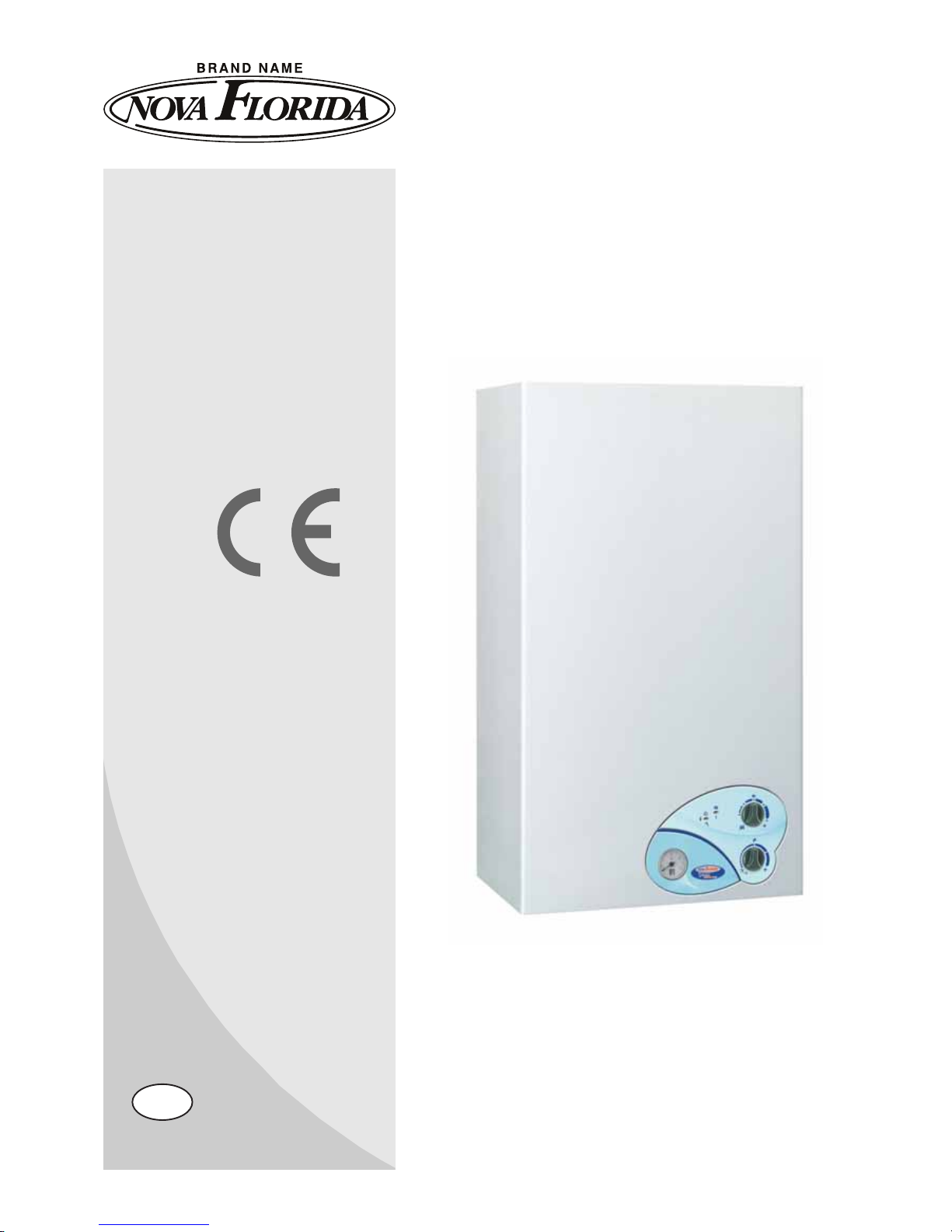
CTN 24/RTN 24 CTFS 24/RTFS 24
CTFS 28/RTFS 28
INSTALLATION
USE AND MAINTENANCE
GB
IST 04 C 167 - 02
VELA
COMPACT
Page 2

2
Dear Customer,
Thank you for choosing and buying one of our boilers. Please read these instructions carefully in order to install, operate, and
maintain this equipment properly.
Page 3

3
General information for fitters, maintenance technicians and users
T
his INSTRUCTION MANUAL, which is an integral and indispensable part of the product, must be handed over to the user by the
i
nstaller and must be kept in a safe place for future reference. The manual must accompany the boiler should it be sold or its pos
s
ession transferred. Following the boiler installation, the tter is to advise the user about boiler operation and its safety devices
T
his boiler must be used for the purposes for which it has been intended. Any other use shall be considered incorrect and
th
erefore dangerous.
T
he boiler must be installed by qualied personnel, in compliance with applicable laws and standards and according to the manu
f
acturer’s instructions given in this manual. Incorrect installation may cause injury to persons and/or animals and damage to proper
t
y. The manufacturer shall not be held liable for any such injury and/or damage.
D
amage and/or injury caused by incorrect installation or use and/or damage and/or injury due to non-observance of the manufac
t
urer’s instructions shall relieve the manufacturer from any and all contractual and extra-contractual liability.
Bef
ore installing the boiler, check that the technical data correspond to the requirements for its correct use in the system.
C
heck that the boiler is intact and it has not been damaged during transport and handling. Do not install equipment which is dama
g
ed and/or faulty.
D
o not obstruct the air suction and/or heat dissipation openings.
O
nly manufacturer approved and supplied accessories or optional kits (including electric ones) are to be installed.
P
roperly dispose of the packaging as all the materials can be recycled. The packaging must therefore be sent to specic waste
m
anagement sites.
K
eep the packaging out of the reach of children as it may represent a choking and suffocation hazard.
n the event of failure and/or faulty functioning, switch off the boiler. Do not attempt to make repairs: contact qualied technicians.
anufacturer approved and supplied parts must be used for all repairs to the boiler.
on-observance of the above requirements may affect the safety of the boilers and endanger people, animals and property.
he manufacturer, in order to guarantee efficient and correct functioning of the equipment, recommends the boiler to be
erviced and repaired by an authorized Service Centre.
outine boiler maintenance is to be performed according to the schedule indicated in the relevant section of this manual.
A
ppropriate boiler maintenance ensures efficient operation, environment preservation, and safety for people, animals and
bjects.
n the event of long periods of inactivity of the boiler, disconnect it from the power mains and close the gas tap.
arning! Should power mains be disconnected, boiler electronic anti-freeze function will not be operative.
hould there be a risk of freezing, add antifreeze: it is not advisable to empty the system as this may result in damage; use specic
nti-freeze products suitable for multi-metal heating systems.
MPORTANT
f you smell gas:
do not turn on or off electric switches and do not turn on electric appliances;
do not ignite ames and do not smoke;
close the main gas tap;
open doors and windows;
contact a Service Centre, a qualified installer or the gas supply company.
ever use flames to detect gas leaks.
he boiler is designed for installation in the country indicated on the technical data plate: installation in any other
ountry may be a source of danger for people, animals and property.
Page 4

4
CONTENTS
General information for the Installer, Maintenance Technician and User Page 3
1. Instructions for the User Page 6
1.1 Control panel Page 6
1.2 Operating the boiler Page 7
1.2.1 Switching on Page 7
1.2.2 Operation Page 7
1...3 Boiler shut-down Page 8
1.3.1 Burner shut-down Page 8
1.3.2 Shut-down due to overheating Page 8
1.3.3 Shut-down due to low water pressure Page 8
1.3.4 Shut-down due to incorrect air/ue gas system draught Page 8
1.3.5 Shut-down due to malfunction of temperature probes Page 8
1.4 Maintenance Page 9
1.5 Notes for the User Page 9
2. Technical characteristics and dimensions Page 10
2.1 Technical characteristics Page 10
2.2 Dimensions Page 11
2.3 Hydraulic layouts Page 13
2.4 Operating data Page 14
2.5 General characteristics Page 15
3. Instructions for the Installer Page 16
3.1 Installation Standards Page 16
3.2 Installation Page 16
3.2.1 Packaging Page 16
3.2.2 Choosing where to install the boiler Page 16
3.2.3 Positioning the boiler Page 17
3.2.4 Installing the boiler Page 18
3.2.5 Boiler room ventilation Page 18
3.2.6 Air intake and ue gas discharge system Page 18
3.2.6.1 Natural draught boiler Page 18
3.2.6.2 Forced draught boiler Page 20
3.2.6.2.1 Conguration of air intake and ue gas discharge ducts Page 20
3.2.6.2.2 Air intake and ue gas discharge system via 100/60 mm coaxial pipes Page 21
3.2.6.2.3 Air intake and ue gas discharge system via 80/80 mm split pipes Page 22
3.2.7 Checking combustion efciency Page 23
3.2.7.1 Coaxial pipe system Page 23
3.2.7.2 Split pipe system Page 23
3.2.8 Gas mains connection Page 24
3.2.9 Plumbing connections Page 24
3.2.10 Power mains connection Page 25
3.2.11 Room thermostat connection (optional equipment) Page 25
3.3 Loading the system Page 25
3.4 Starting the boiler Page 26
3.4.1 Preliminary checks Page 26
3.4.2 Switching on and switching off Page 26
3.5 Wiring diagram Page 26
3.6 Adaptation to other gas types and burner adjustment Page 29
4. Testing the boiler Page 30
4.1 Preliminary checks Page 30
4.2 Switching on and switching off Page 30
5. Maintenance Page 31
6. Troubleshooting Page 32
Page 5

5
PICTURE INDEX
Pic. 1 – Control panel Page 6
Pic. 2 – Loading tap Page 8
Pic. 3 – CTN model dimensions Page 11
Pic. 4 – CTFS model dimensions Page 12
Pic. 5 – CTN model hydraulic layout Page 13
Pic. 6 – CTFS model hydraulic layout Page 13
Pic. 7 – Installation template Page 17
Pic. 8 – Connection to chimney system of CTN model Page 19
Pic. 9 – Dimensions for connection of CTN model to the ue gas discharge duct Page 19
Pic. 10 – Air intake and ue gas discharge coaxial pipe system (CTFS) Page 21
Pic. 11 – Dimensions for connection to air intake and ue gas discharge coaxial pipe system (CTFS) Page 21
Pic. 12 – Air intake and ue gas discharge split pipe system (CTFS) Page 22
Pic. 13 – Dimensions for connection to air intake and ue gas discharge split pipe system (CTFS) Page 22
Pic. 14 – Split pipe system examples Page 23
Pic. 15 – Additional split pipe system examples Page 23
Pic. 16 – Sample areas for combustion efciency measurement Page 23
Pic. 17 – Gas mains connection Page 24
Pic. 18 – Electric layout Page 27
Pic. 19 – Natural gas – Lpg selection jumper Page 29
Pic. 20 – Gas valve adjustment Page 29
CHART INDEX
No. 1 chart – Led signaling – boiler operation status Page 6
No. 2 chart – CTN model adjustment rates Page 14
No. 3 chart – CTFS model adjustment rates Page 14
No. 4 chart – General specications Page 15
No. 5 chart – CTN 24 model combustion rates Page 15
No. 6 chart – CTFS 24 AF model combustion rates Page 15
No. 7 chart – “temperature – nominal resistance” chart of temperature probes Page 28
Page 6
6
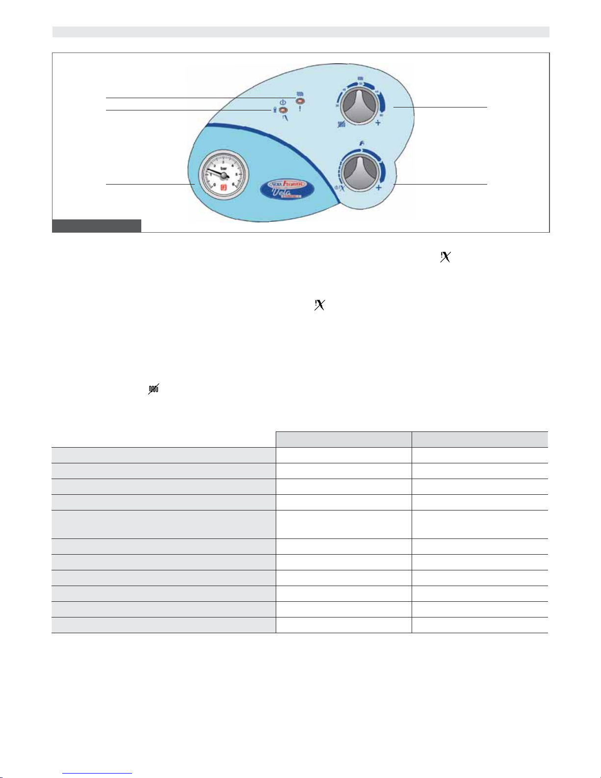
1. Boiler working mode led (multi-color)
See no. 1 chart at the bottom of the page for further details on
color displayed by led in relation to boiler working mode.
2. Boiler working mode led (multi-color)
See no. 1 chart at the bottom of the page for further details on
color displayed by led in relation to boiler working mode.
3. Water pressure gauge
The gauge shows water pressure in the CH system.
4. CH selector and adjusting knob
The knob activates or de-activates CH operation, and adjusts CH
water temperature between a minimum of 35°C and a maximum
of 78°C.
When the knob is set to
(fully turned counter-clockwise), the
boiler is set to summer mode and CH operation is de-activated.
4. DHW selector and boiler shutdown reset
The knob sets the boiler to stand-by (
position, fully turned counter-clockwise), and adjust DHW temperature between a minimum
of 35°C and a maximum of 58°C.
When the boiler has shut down is to be reset by turning the knob
to
position.
WARNING
The boiler has a special built-in regulator limiting DHW flow up to
10 liter per minute. In addition to the setting of no. 5 selector,
the temperature of the DHW supplied also depends on the flow
requested by the user and the temperature of the water mains
supply.
1. INSTRUCTIONS FOR THE USER
1.1 CONTROL PANEL
Pic. 1 – Control panel
1
2
3 5
4
No. 1 Chart – Color displayed by led in relation to boiler operation status
LED 1 LED 2
Power connected to boiler n/a GREEN
Flame presence n/a YELLOW
Active CH mode GREEN n/a
Shutdown due to flame absence OFF RED
Flue gas thermostat shutdown (CTN)
Air/flue gas pressure switch shutdown (CTFS)
YELLOW OFF
Safety thermostat shutdown RED OFF
Safety thermostat shutdown FLASHING GREEN OFF
Gas valve alarm FLASHING YELLOW OFF
Water pressure switch alarm (>85°) FLASHING RED n/a
CH flow probe alarm FLASHING YELLOW/RED OFF
DHW flow probe alarm FLASHING GREEN/RED OFF
KEY CHART TO ACHRONYMS
OFF LED off
RED LED on, displaying the color stated in the chart
FLASHING RED LED flashing, displaying the color stated in the chart
RED/GREEN LED flashing, displaying in sequence the colors stated in the chart
n/a LED status is not relevant
Page 7
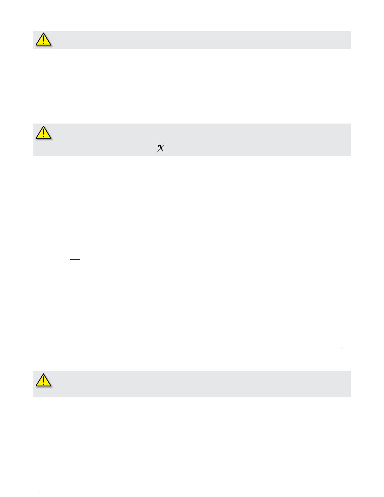
The following procedures are to be implemented only after the boiler is installed, tested and its installation is certified
a qualified fitter.
Open the gas stop cock.
connect power mains to the boiler (no.
LED turns on displaying the green color);
choose boiler mode by means of no.
selector (pic. 1);
set the desired central heating water temperature by means of no.
adjusting knob (pic. 1);
set the desired domestic hot water temperature by means of no. 5 adjusting knob (pic. 1);
set room temperature by means of room thermostat (when available).
hen CH is required, no. 1 LED turns on ( green ).
hen ame is present no.
LED turns on ( yellow ).
hould the boiler be left inactive for a long time, particularly if boiler is lpg powered, ignition might be difficult.
efore starting the boiler switch on another gas powered device (e.g. kitchen range).
eware that even by following that procedure, the boiler might still shut down once or twice.
eset the boiler by turning no. 5 knob to reset position for a few seconds.
.2.2. Operation
T
o prevent frequent ignition and switching off in the heating mode, the boiler has a waiting time of
minutes between subsequent
nitions.
hould water temperature in the system fall below
°C, the waiting time is disallowed and the boiler re-ignites.
oiler electronics always gives priority to DHW over CH supply.
Temp
erature can be adjusted within a
°C to 58°C range.
T
he boiler is tted with a ow-limiting device that allows a maximum DHW ow of 10 liter per minute.
A
vailable DHW liters per minute depend on boiler thermal output and water mains supply temperature, according to the following
ormula:
= DHW liter = 4 (CTFS model) or
3
8/∆t (for CTN model
)
∆t
here ∆t = DHW temperature – water mains supply temperature
.g. when water mains supply temperature is 8°C and DHW is required at
°C, the value of ∆t is:
=
°C – 8 °C =
°C
nd DHW liters per minute) obtainable at the required temperature of
°C are:
=
= 11.[liters per minute] (mixed water to the tap - for model CTFS).
T
he boiler is equipped with an anti-frost protection system which is not active when the boiler is in stand-by mode.
hen central heating water temperature sensor detects a water temperature of 5°C, the boiler switches on and stays on at its mini
um heating output until the temperature of central heating water reaches
°C or 15 minutes have elapsed.
hould the boiler shut down, pump operation is in any case granted.
he anti-freeze function only protects the boiler and not the central heating system.
he central heating system must be protected by using an ambient thermostat, although it is disabled when
e selector is set to stand-by.
T
he heating system can be effectively protected against icing by using specic anti-freeze products that are suitable for multi-metal
ystems. Do not use anti-freeze products for car engines, and check the effectiveness of the product used over time.
here the boiler is left inactive and still connected to power the pump is activated for
seconds every
hours to prevent seizure.
1.2 Operating the Boiler
1.2.1 Switching On
Page 8
.3. Boiler shut-down
hen any malfunction occurs, the boiler automatically shuts down.
efer to no. 1 chart (on page 6) in order to detect the boiler operation status.
n order to identify plausible malfunction origin, see no. 6 paragraph “Troubleshooting”at the end of the manual.
n relation to the type of malfunction, proceed as described hereafter.
.3.1. Burner shut-down
hen the burner shuts down, no.
LED turns on (red). Should this happen proceed as follows:
Once gas presence is veried, reset the burner by turning no. 5 selector (pic. 1) to its reset position : if the equipment does not
estart and shuts down again, after performing two attempts, contact an authorized Service Centre or qualied personnel for service.
hould the burner shut down frequently, signaling a recurrent operation malfunction contact an authorized Service Centre or qualied
ersonnel for service.
.3.2. Shut-down due to overheating
hen central heating ow overheats, no. 1 LED (pic. 1) ashes (red). Should that happen, contact an authorized Service Centre or
ualied personnel to carry out maintenance work.
.3.3. Shut-down due to low water pressure
n case of shutdown due to water pressure switch intervention, no. 1 LED ashes (yellow).
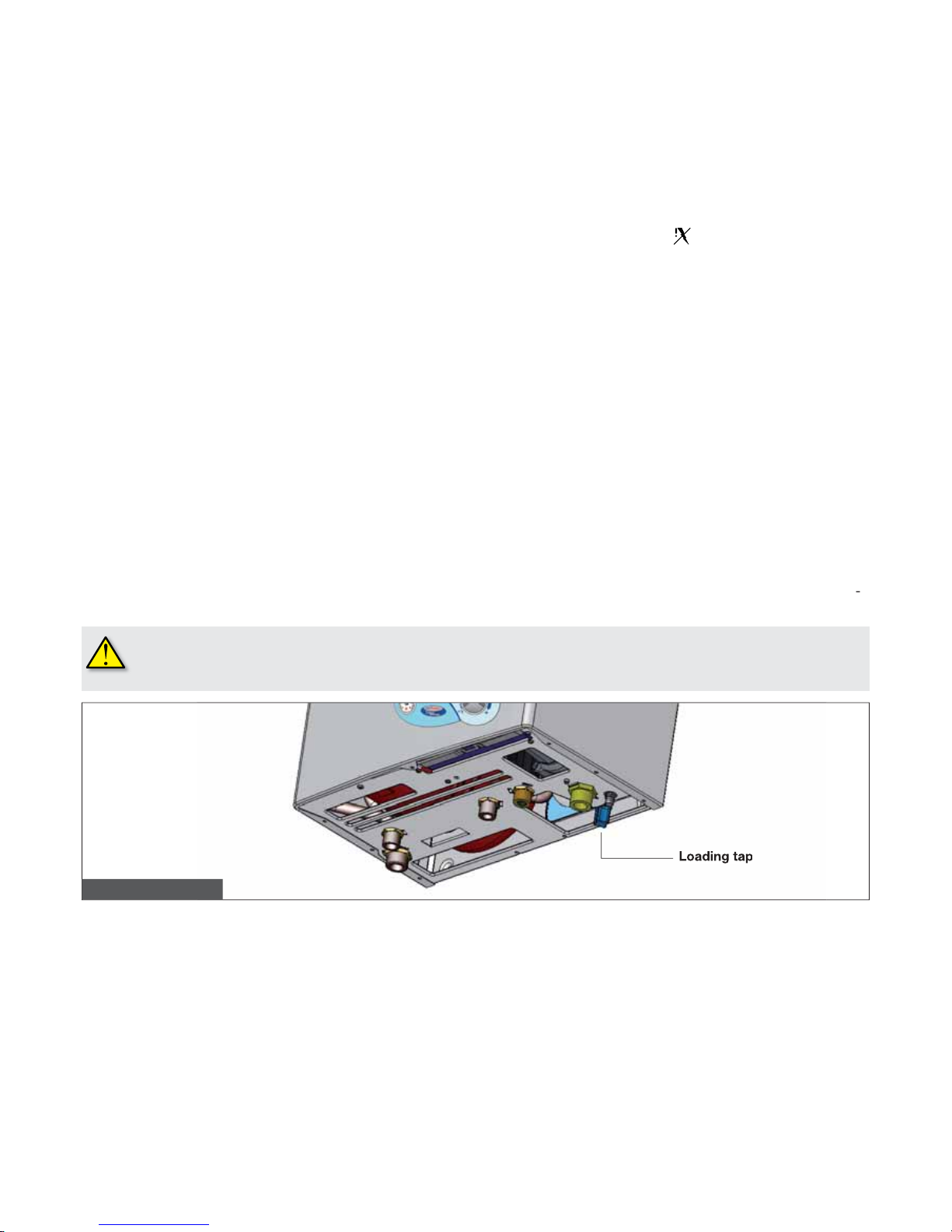
ill up the boiler by opening the loading tap A (pic. ), located in the lower area of the boiler, next to the hydraulic connections.
ater pressure must be 1-1.bars w
hil
e the boiler is cold.
n order to restore water pressure, proceed as follows:
Turn the lling tap counter-clockwise to let water into the boiler and keep it open until no. 5 pressure gauge (pic. 1) shows that a
ressure of 1-1,bars is reached; now close the tap by rotating it clockwise.
hould boiler shuts down frequently occur it means there is boiler malfunction in progress. Contact qualied personnel or an authori
ed Service Centre for maintenance.
nce the system is filled, close the tap properly. If the tap is not properly closed, as pressure increases,
oiler safety valve may open and water flow out.
.3.4 Shut-down due to flue system incorrect draught
hould the boiler shut down due to an anomaly in the air intake and/or ue gas discharge system, no. 1 LED (pic. 1) turns on ( yellow
)
. Should that occur, contact an authorized Service Centre or qualied personnel for maintenance.
.3.5 Shut-down due to malfunction of temperature probes
hould the burner shut down due to a malfunction of the temperature probes, no. 1 LED (pic. 1) ashes as follows:
yellow/red for CH probe;
red/green for DHW probe.
hen that happens, contact an authorized Service Centre or qualied personnel to carry out maintenance.
Pic. 2 - Loading tap
Page 9

.4. Maintenan
ce
Have routine boiler maintenance performed according to the schedule indicated in the relevant section of this manual
.
A
ppropriate boiler maintenance ensures efficient operation, environment preservation, and safety for people, animals and objects.
nly qualified personnel are to service the boiler.
The manufacturer recommends Customers to contact authorized Service Centers for maintenance and repairs, they are best qualified
f
or that procedure
.
he user may only clean the external casing of the boiler, employing common household products.
o not use water
!
.5. Notes for the User
T
he user may only access boiler parts which can be reached without using technical equipment and/or tools: therefore the user is not
uthorized to remove the boiler casing and act upon inside components.
obody, including qualied personnel, is authorized to modify the boiler.
T
he manufacturer shall not be held responsible for damage to people, animals, or property due to tampering or improper intervention
the boiler.
hen the boiler remained inactive and disconnected from power mains supply for a long period of time, pump unblocking procedure
ay be necessary.
T
he above mentioned procedure involves boiler casing removal in order to access the inside of the boiler and must therefore be
mplemented by qualied personnel.
ump blockage may be prevented by adding to the water in the CH system, specic protective, lm-producing products, suitable for
ulti-metal CH systems.
Page 10

10
2. Technical Characteristics and Dimensions
2.1. Technical Characteristics
The boiler is equipped with an integrated gas atmospheric burner and the following versions are available:
- CTN 24 AF: open chamber, natural draught boiler with electronic ignition and instantaneous DHW supply;
- CTFS 24 AF: sealed chamber, forced draught boiler with electronic ignition and instantaneous DHW supply;
Both models are equipped with ionization ame detection device.
The boilers meet applicable requirements of laws enforced in the country of destination and shown in their data plate
Installation in a country other than specied might be source of hazard to people, animals and objects.
The principal technical characteristics of the boilers are listed below:
Construction Characteristics
- Bi-thermal, high performance, copper heat exchanger.
- CH pump with integrated air purging device.
- 6-litre expansion vessel.
- Safety pressure switch, preventing low water pressure operation.
- DHW priority ow switch.
- 10 liter/min DHW ow limiting device.
- Boiler loading and unloading taps.
- DHW and CH temperature probes.
- Safety limit thermostat.
- IPX4D electrically protected control panel.
- Integrated safety and modulation electronic board.
- Electronic ignition and ionization ame detection device.
- Air/ue gas pressure switch (CTFS).
- Flue gas thermostat (CTN).
- Twin shutter, modulating gas valve.
User Interface
- Central heating selector/adjusting knob (35°C/78°C range).
- Boiler shutdown reset/DHW adjusting knob ( 35°C/58°C range).
- System water pressure gauge.
- Light emitting indicators for:
• Power ON;
• CH supply;
• ame detection;
• burner shut-down;
• gas valve alarm;
• burner shut-down due to overheating;
• burner shut-down due to air/ue gas pressure switch intervention (CTFS);
• burner shut-down due to faulty chimney draught (CTN);
• insufcient water pressure in the system;
• malfunction of temperature probes.
Functional characteristics
- DHW priority function.
- Electronic ame modulation in CH mode, with timed rising ramp.
- Electronic ame modulation in DHW mode.
- Boiler anti-frost function (ON: 5°C, OFF: 30°C or after 15 minutes operation).
- Flame propagation function during ignition procedure (CTFS).
- Timer controlled ambient thermostat (240 seconds with CH ow temperature > 40°C).
- Post-circulation function of pump in CH and anti-frost modes (30 seconds).
- Post-circulation function of pump in DHW (6 seconds in winter mode, 1 second in summer mode).
- Post-ventilation function in DHW mode and only when boiler is set to summer (10 seconds – CTFS).
- Post ventilation safety function after boiler shutdown of malfunction of probes (1 minute – CTFS).
- Pump anti-blocking function (30 seconds of pump operation each 24 hours of boiler inactivity).
Page 11
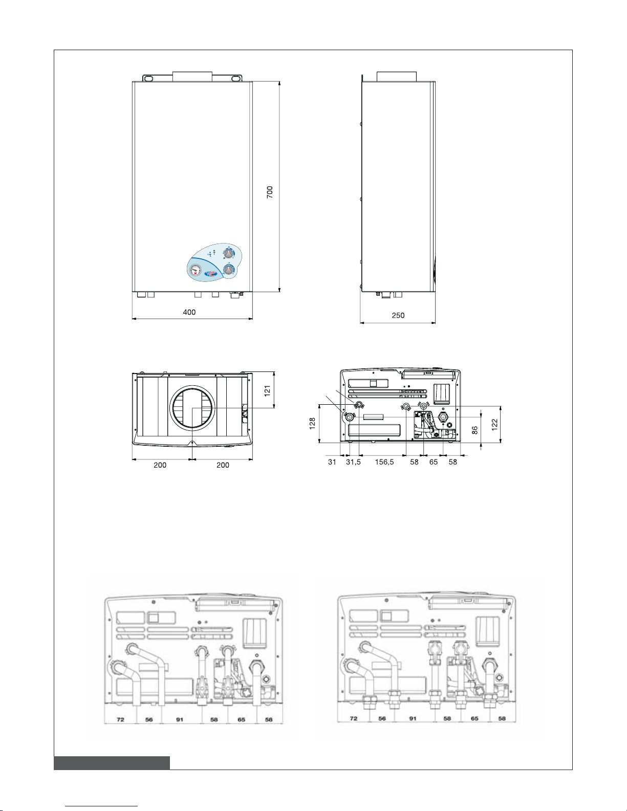
11
2.2 Dimensions
M
C
G
F
R
0
1
3
6
5
42
bar
3
42
bar
Model CTN
Pic. 3 – CTN model dimensions
bottom view
top view
G Gas inlet (1/2”)
M CH flow (3/4”)
C DHW flow (1/2”)
F Cold water inlet (1/2”)
R CH return (3/4”)
Dimensions for connection to base hydraulic kit (option)
Dimensions for connection to “plus” hydraulic kit (option)
Page 12
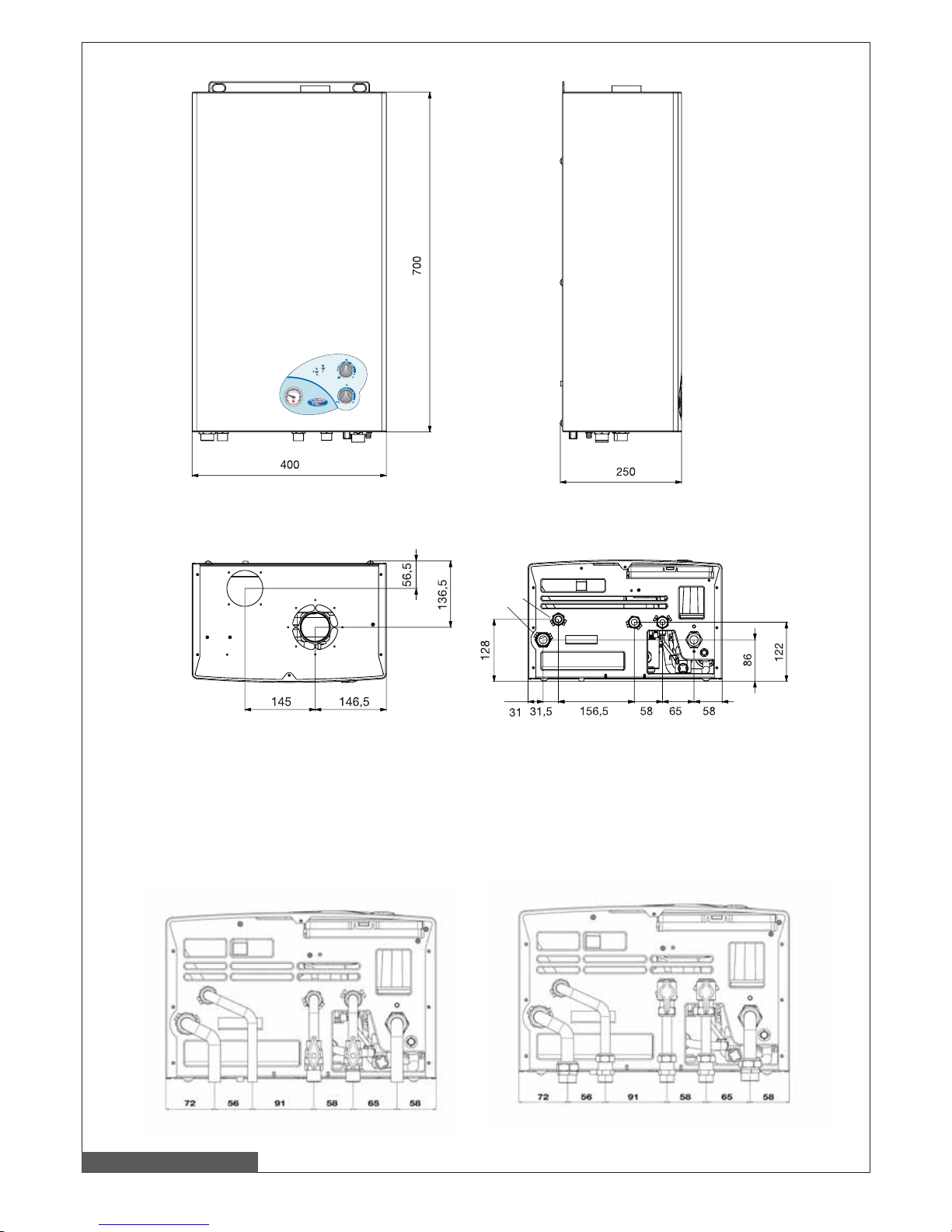
12
M
C
G
F
R
0
1
3
6
5
42
bar
3
42
bar
Model CTFS
Pic. 4 – CTFS model dimensions
top view bottom view
G Gas inlet (1/2”)
M CH flow (3/4”)
C DHW flow (1/2”)
F Cold water inlet (1/2”)
R CH return (3/4”)
Dimensions for connection to base hydraulic kit (option)
Dimensions for connection to “plus” hydraulic kit (option)
Page 13
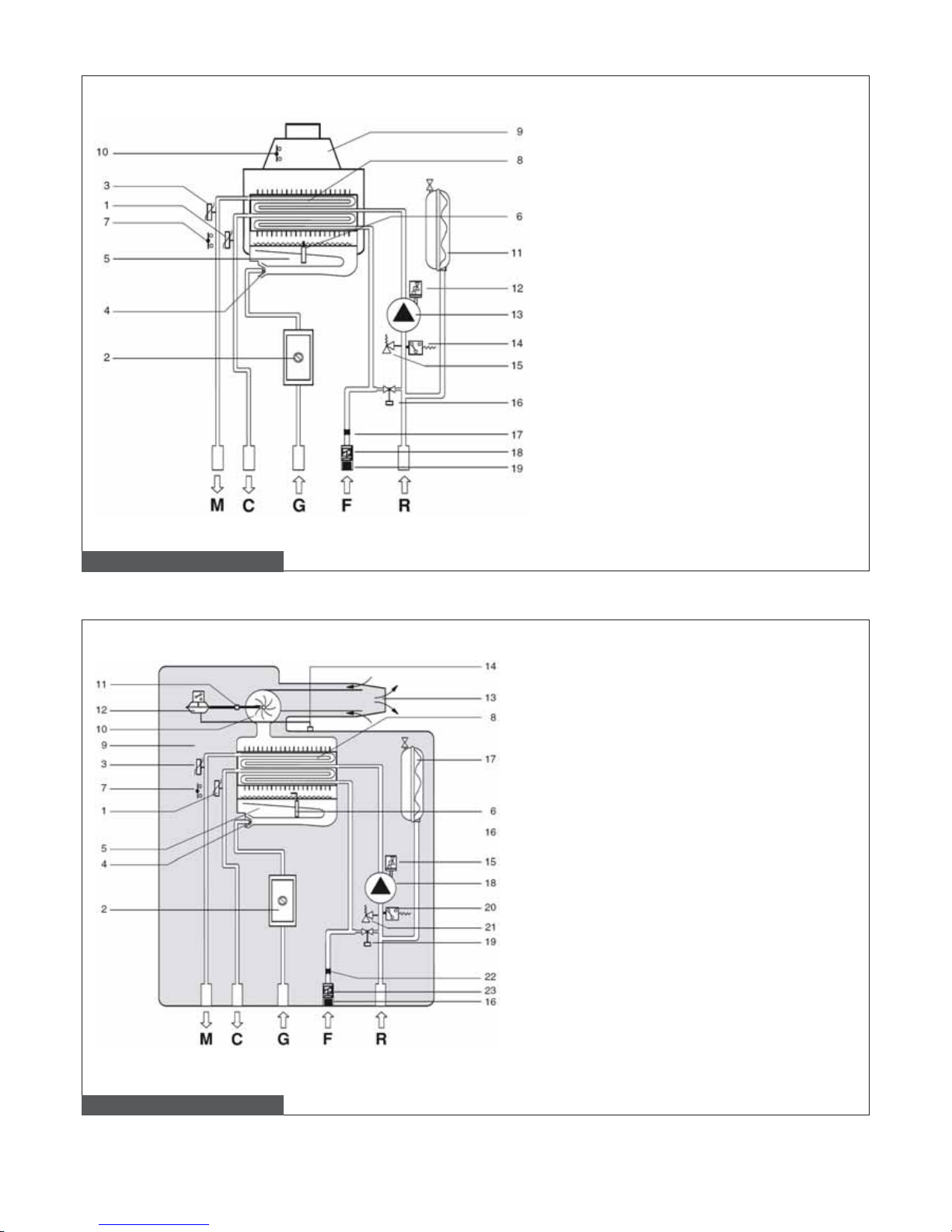
13
2.3 Hydraulic layouts
Pic. 5 – Hydraulic layout CTN model
Pic. 6 – Hydraulic layout CTFS model
1. DHW temperature probe
2. Modulating gas valve
3. CH temperature probe
4. Burner nozzles
5. Burner
6. Ignition/ame sensing electrode
7. Safety thermostat
8. Bi-thermal heat exchanger
9. Flue gas hood
10. Flue gas thermostat
11. Expansion vessel
12. Air purging device
13. Pump
14. Water pressure switch
15. 3 bar safety valve
16. Loading tap
17. DHW ow limiting device – 10 liter per
minute
18. Domestic cold water ow switch
19. Domestic cold water inlet lter
M CH ow
C DHW ow
G Gas intake
F Water mains inlet
R CH return
1. DHW temperature probe
2. Modulating gas valve
3. CH temperature probe
4. Burner nozzles
5. Burner
6. Ignition/ame sensing electrode
7. Safety thermostat
8. Bi-thermal heat exchanger
9. Sealed combustion chamber
10. Flue gas discharge fan
11. Flue gas check
12. Air/ue gas safety pressure switch
13. Air/ue gas coaxial ducts
14. Air check
15. Air purging device
16. Domestic cold water inlet lter
17. Expansion vessel
18. Pump
19. Loading tap
20. Water pressure switch
21. 3 bar safety valve
22. DHW ow limiting device – 10 liter per
minute
23. Domestic cold water inlet ow switch
M CH ow
C DHW ow
G Gas intake
F Water mains inlet
R CH return
Page 14
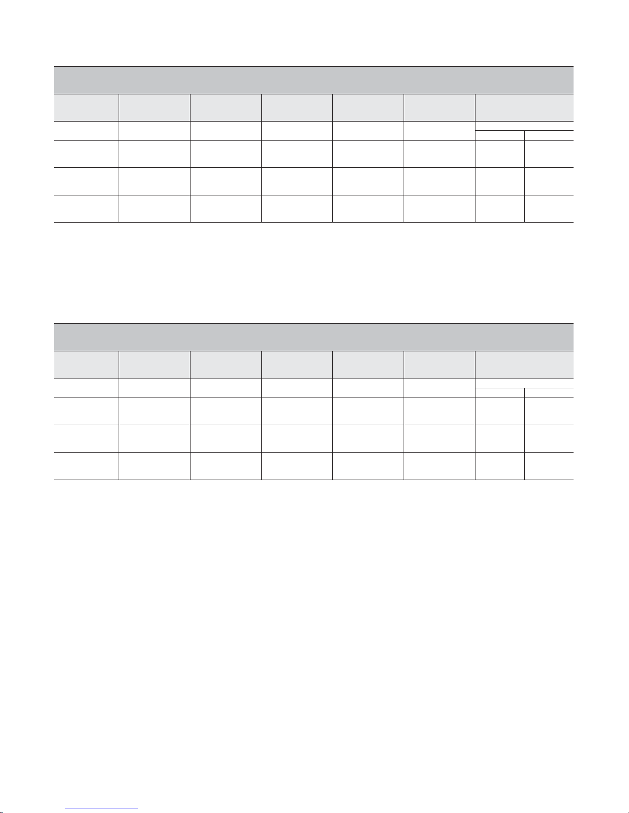
14
2.4 Operating Data
Below indicated burner pressures are to be checked after a three minute boiler operation.
CTN 24 AF
Function
Max. heat
input
Max. heat
output
Min. heat
output
Gas mains inlet
pressure
Diameter of
nozzles
Burner pressure
(kW) (kW) (kW) (mbar) (mm)
(mbar)
min max
Methane Gas
G20
24.5 22.2 10.8 20 1.30 3.2 12.5
Butane Gas
G30
24.5 22.2 10.8 29 0.78 6.6 27.5
Propane Gas
G31
24.5 22.2 10.8 37 0.78 8.5 35.5
No. 2 chart – CTN model adjustment data
Hot water supply ∆T 45°C = 7,1 l/min
Hot water supply ∆T 40°C = 8,0 l/min
Hot water supply ∆T 35°C = 9,1 l/min
Hot water supply ∆T 30°C = 10,6 l/min*
Hot water supply ∆T 25°C = 12,7 l/min*
*mixed water to the tap
CTFS 24 AF
Function
Max. heat
input
Max. heat
output
Min. heat
output
Gas mains inlet
pressure
Diameter of
nozzles
Burner pressure
(kW) (kW) (kW) (mbar) (mm)
(mbar)
min max
Methane Gas
G20
25,5 23,7 11,2 20 1,35 3,0 12,5
Butane Gas
G30
25,5 23,7 11,2 29 0,80 7,0 28,0
Propane Gas
G31
25,5 23,7 11,2 37 0,80 9,5 36,0
No. 3 chart – CTFS model adjustment data
Hot water supply ∆T 45°C = 7,5 l/min
Hot water supply ∆T 40°C = 8,5 l/min
Hot water supply ∆T 35°C = 9,7 l/min
Hot water supply ∆T 30°C = 11,3 l/min*
Hot water supply ∆T 25°C = 13,6 l/min*
*mixed water to the tap
Page 15
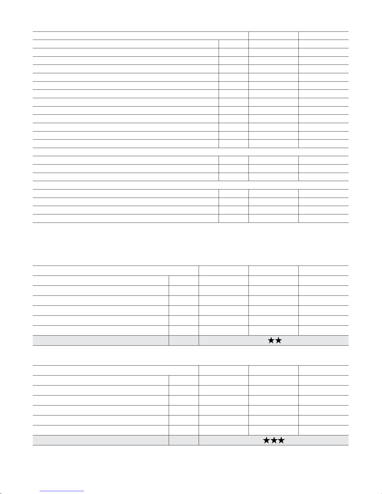
15
2.5 General Characteristics
CTN 24 AF CTFS 24 AF
Equipment category - II2H3+ II2H3+
Number of burner nozzles installed n° 11 11
Minimum CH ow rate l/h 550 550
Minimum CH pressure bar 0.5 0.5
Maximum CH pressure bar 3 3
Minimum DHW pressure bar 0.5 0.5
Maximum CH pressure bar 8 8
DHW specic capacity (∆t 30 °C) l/min 10.6 11.3
Electric power Supply – Voltage / Frequency V - Hz 230-50 230-50
Power mains supply fuse A 2 2
Maximum power consumption W 80 140
Electric protection rating IP X4D X4D
Net weight Kg 24.9 27.5
Methane gas consumption (*) m
3
/h 2.59 2.70
Butane gas consumption kg/h 1.93 2.01
Propane gas consumption kg/h 1.90 1.98
Maximum CH working temperature °C 83 83
Maximum DHW working temperature °C 58 58
Total capacity of expansion vessel l 6 6
Maximum recommended CH system capacity (**) l 100 100
No. 4 chart – General characteristics
(*) Value related to 15°C – 1013 mbar condition
(**) Maximum water temperature of 83°C, vessel preloaded at 1 bar.
CTFS 24 AF Max. heat output Min. heat output 30% load
Casing heat loss % 1.2 0.4 -
Flue system heat loss with burner on % 5.8 11.7 -
Flue system mass capacity (methane gas) g/s 16.0 16.9 -
Flue temp.– air temp. °C 107 77 -
CO
2
(methane - propane - butane) % 6.3 / 7.2 / 7.0 2.7 / 3.3 / 3.2 -
Boiler efciency rating % 93.0 90.2 90.2
92/42/CEE rating
No. 6 chart – Combustion data CTFS 24 AF model
CTN 24 AF Max. heat output Min. heat output 30% load
Casing heat loss % 3.2 2.7 -
Flue system heat loss with burner on % 6.1 9.4 -
Flue system mass capacity (methane gas) g/s 16.7 16.5 -
Flue temp.– air temp. °C 85 66 -
CO
2
(methane - propane - butane) % 5.7 / 7.4 / 7.3 2.7 / 3.8 / 3.7 -
Boiler efciency rating % 90.6 90.0 90.0
92/42/CEE rating
No. 5 chart – Combustion data CTN 24 model
Page 16

T
he boiler is designed as II
category and is to be installed in compliance with laws and standards in force in the country of instal
ation.
.2. Installation
nstallation and maintenance procedures are to be implemented employing exclusively accessories and spare parts which
re approved and supplied by the manufacturer. Correct boiler operation is not guaranteed when using accessories and
are parts which are not manufacturer approved and supplied.
.2.1. Packagin
g
T
he boiler is shipped in a sturdy cardboard box.
emove boiler from cardboard box and check its integrity.
T
he packing materials can be recycled: disposal of must be managed via specic waste collection sites.
eep packaging out of the reach of children, as it may be source of danger.
T
he manufacturer shall not be held responsible for damage to people, animals, or property due to failure in following the above men
ioned instructions.
ackaging includes one plastic bag containing:
installation, use and maintenance manual;
wall mounting template (pic. 7);
) two screws and wall plugs in order to afx the boiler to the wall;
in CTFS model: one diaphragm for ue gas discharge (diameter
5);
) in CTFS model: one sealing caps with gasket.
.2.2. Choosing where to install the boiler
T
he following must be taken into account when choosing where to install the boiler:
the indications given in … “Flue gas discharge system” paragraph;
check the wall to be adequately well-built avoiding to t the boiler on fragile walls;
after the installation, check that 1 cm to the right and 1 cm to the left of the boiler was left for casing removal;
Do not t the boiler above any equipment that may prejudice proper operation (steam and grease vapor emitting kitchen appliances,
ashing machines, etc.);
Do not install boilers with a natural draught in rooms with a corrosive or very dusty atmosphere, such as hair salons, laundries, etc.,
s that may greatly reduce boiler lifespan.
3. INSTRUCTIONS FOR THE INSTALLER
3.1 INSTALLATION STANDARDS
Page 17
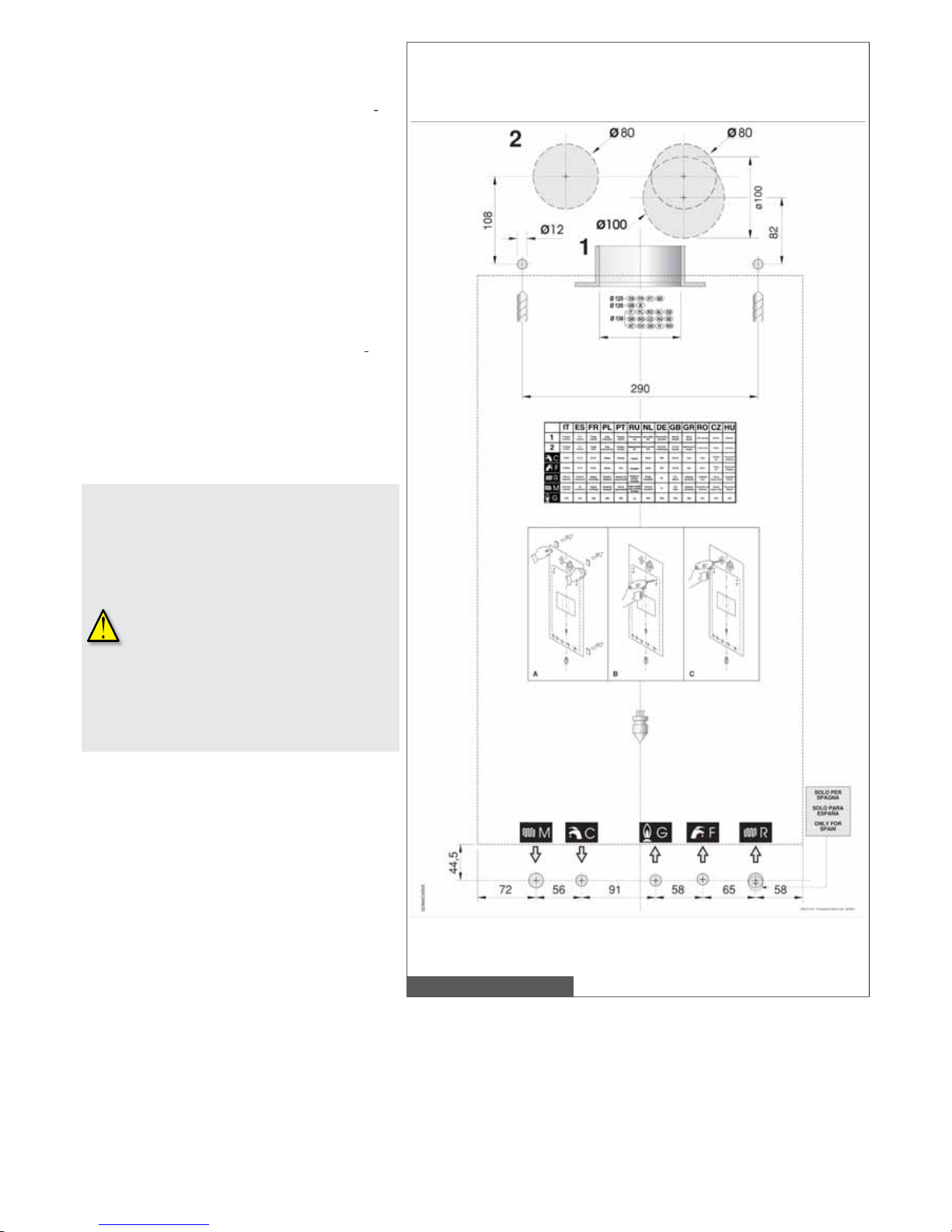
pic. 7 - Template
.2.3. Positioning the Boiler
ach unit is supplied along with a paper template, in
he package, allowing positioning the pipes connec
ing CH system, DHW system, gas supply, and air
ntake/ue gas discharge ducts to the boiler before
nstalling the boiler itself.
T
he template is made of highly resistant paper and is
be afxed to the wall on which the boiler is to be
ounted using a carpenter’s level. It provides all the
ndication required in order to drill the holes for xing
he boiler to the wall, the boiler is secured to the wall
sing two screws and wall plugs.
T
he lower part of the template shows the areas to be
arked for the couplings positioning of boiler con
ection to the gas supply pipe, water mains supply
ipe, DHW ow pipe, CH ow and return pipes.
T
he upper part of the template shows the areas to
e marked for positioning of air intake and ue gas
scharge ducts.
ince the temperature of the walls on
ch the boiler is mounted and the
emperature of coaxial flue system do
ot exceed 60°C, minimum distances
f
rom flammable walls do not need to be
rranged.
r boilers with split pipe flue system, in
resence of flammable walls and
assages through such walls, provide
nsulating layer between wall and
fl
ue pipes.
Page 18

.2.4. Insta
lling the Boil
er
efore connecting the boiler to the CH and DHW pipe systems, clean the pipes carefully and eliminate
ny metal left during manufacturing and welding process, any oil or grease that may be left and that could damage
he boiler or alter its operation if it reaches the boiler.
Do not use solvents as they could damage components
.
xclusively employ original and manufacturer supplied, air intake/flue gas discharge systems in order to ensure correct
oiler operation
e manufacturer shall not be held respons
ible i
n case of damage to people, animals, or property due to failure
n following the above mentioned information.
n order to install the boiler, proceed as follows:
fx the template to the wall;
heck that 1 cm to the right and 1 cm to the left of the boiler is left for casing removal;
rovide two 1
mm Ø holes in the wall for the boiler wall plugs, insert the wall plugs provided with the boiler and place in the screws;
hen necessary provide holes in the wall to allow air intake and/or ue gas discharge pipes to pass through it;
osition the couplings for connection to the gas supply pipe
(G)
, the cold domestic water supply pipe (F), the domestic cold water ow
ipe (C), and the central heating ow (M) and return pipes (R), as shown on the template (lower area);
ook the boiler to the previously provided screws;
onnect the boiler to the feed pipes;
onnect the boiler to the air intake and ue gas discharge system (refer to
5. and
6. paragraphs);
onnect power supply and ambient thermostat (when available).
.2.5.
Boile
r room vent
ilatio
n
TN boiler model has an open combustion chamber and is designed for connection to a chimney: combustion air
s drawn directly from the room where the boiler is installed.
T
iler m
ode
l has a
sealed combustion chamber and does no
t withdraw com
bustion a
ir from the room where the boiler is
nstalled, so specic recommendations do not need to be applied involving air intake ventilation openings, or concerning boiler room
equirements.
The Manufacturer shall not be held liable for damage resulting in incorrect installation, use, modification of the
quipment or non-observance of instructions provided by the manufacturer or applicable installation standards for
he product.
.2.6. Air intake and flue gas discharge system
n terms of the ue discharge into the atmosphere, comply with applicable laws and prescriptions in the country
f installation.
he boiler is equipped with a safety device which is oversees flue gas exhaustion.
n case of malfunction of the air intake/flue gas discharge system, the device shuts down the equipment and no. 1
ED turns on (yellow).
t is strictly for
bidd
en to tamper or de-activate the safety device.
hould the boiler repeatedly shut down, it is necessary to have the boiler air intake/flue gas discharge ducts checked,
hey could be obstructed or incorrectly sized for flue gas exhaust into the atmosphere.
.2.6.1.
atural draught boiler
onnecting to the chimney
T
he chimney is indispensable for correct boiler operation; it must therefore comply with the following requirements:
it must be made of waterproof material and be resistant to ue gas temperature and related condensate;
it must have appropriate mechanical characteristics and low thermal conductivity;
it must be perfectly sealed;
it must be as vertical as possible and the roof terminal is to have a removable cap for inspection and cleaning;
the chimney diameter is not to be less wide than the boiler ue gas outlet diameter; squared or rectangular section chimneys must
ear an internal section, 10% larger than the section connected to the boiler anti-wind gust device;
starting from the boiler, the duct connecting to the chimney is to follow a vertical direction and must be long not less than twice its
iameter before joining the chimney.
Page 19
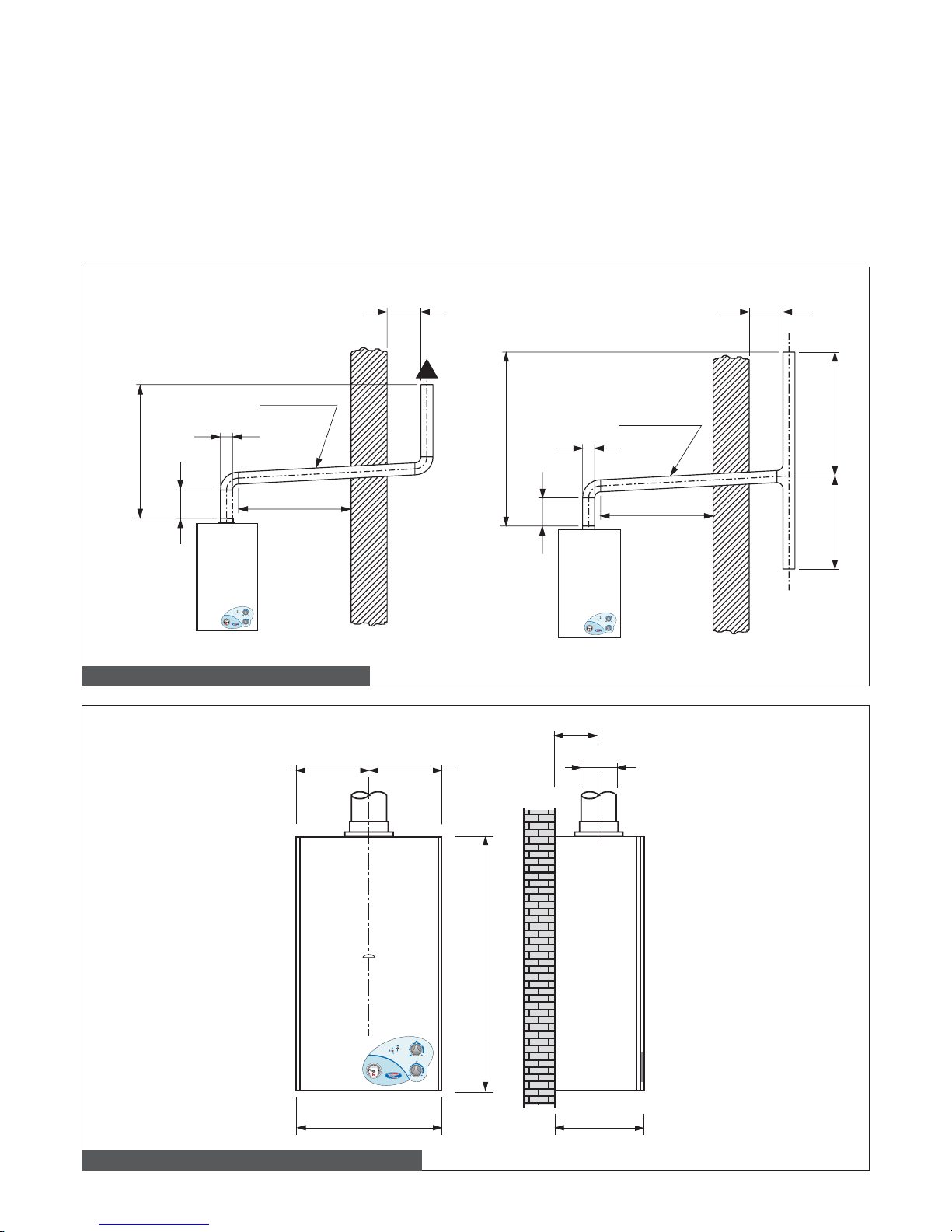
19
Direct emission into the atmosphere
Natural draught boilers can discharge ue gas directly into the atmosphere via a duct which goes through the outside walls of the building and ends with an anti-wind gust device terminal.
The ue gas exhaust duct is to comply with the following requirements:
- its sub-horizontal part inside the building must be as short as possible (not longer than 1,000 mm);
- it is not to have more than 2 direction changes;
- it can host only one single boiler ue gas exhaust system;
- its section, which is passing through the wall is to be protected by a sheath duct; the part of the sheath duct facing the inside of the
building is to be sealed, while the part facing outwards is to be left open;
- its end section, on which the terminal is to installed, is to protrude from the wall of the building for a length of a
least twice the diameter of the duct;
- the terminal is to be positioned no less than 1.5 meters higher than the ue gas exhaust duct from the boiler (see pic. 8).
2 Ø min. 2 Ø min.
1,5 m min.
1,5 m min.
Ø
Ø
2 Ø
2 Ø
1 m max.
1 m max.
Pendenza
min. 3 %
Pendenza
min. 3 %
> 3 Ø > 3 Ø
0
1
3
6
5
42
bar
3
42
bar
0
1
3
6
5
42
bar
3
42
bar
Pic. 8 – Connection to the chimney for CTN model
400
700
250
Ø 130,8
121
200 200
0
1
3
6
5
42
bar
3
42
bar
Pic. 9 – Dimensions for connection of CTN model to the chimney
Slope
Slope
Page 20
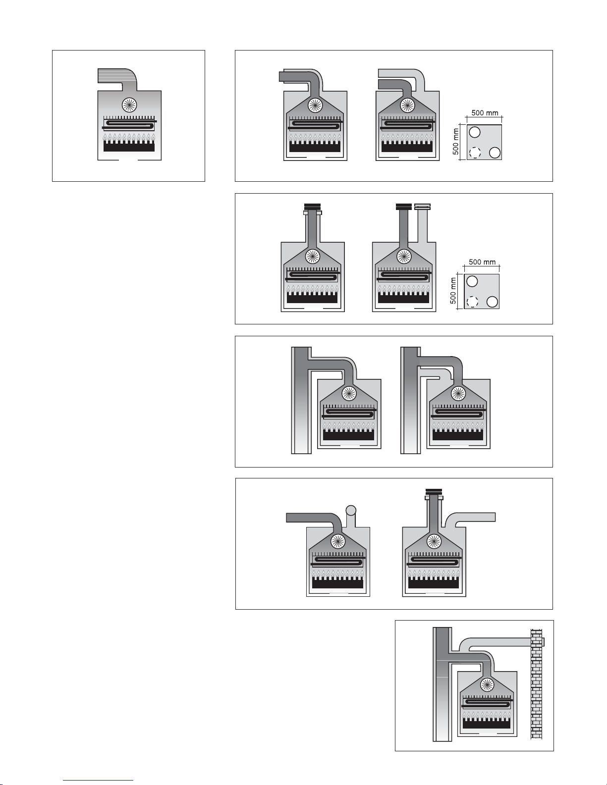
20
3.2.6.2. Forced draught boiler
3.2.6.2.1 Configuration of air intake and flue gas discharge ducts
Type
C12
Type
C32
Type
C42
Type
C52
Type
C82
Type
B22
B22 This boiler is conceived for connection
to an existing ue system either internal or
external to the boiler room. Combustion air
is taken directly from the boiler room itself
while ue gas is conveyed to the outside.
The boiler is not to be tted with an antiwind gust device, while it is to be equipped
with a fan, mounted after the combustion
chamber.
C12 This boiler is designed to be connected to horizontal outlet and intake ducts
connected to the outside by means of
coaxial or split ducts.
The distance between the air intake duct
and the ue gas outlet duct is to be a minimum of 250 mm (refer to the picture on the
lateral area of the page) and both terminals
must be positioned within a squared area
having 500 mm sides.
C32 This boiler is designed to be connected to vertical outlet and intake ducts
connected to the outside by means of coaxial or split ducts. The distance between
the air intake duct and the gas ue duct
is to be a minimum of 250 mm (refer to
the picture on the lateral area of the page)
and both ends must be positioned within a
squared area having 500 mm sides.
C42This boiler is designed to be connected to a collective chimney pipe system
that includes two ducts, one for taking in
combustion-supporting air and the other
for removing the products of combustion.
These ducts may be coaxial or split.
The ue gas chimney system must comply
with current standards.
C52 Boiler with separate pipes for the
combustion supporting air intake and for
removal of the products of combustion.
These ues may discharge in areas at a
different pressure. The terminals may not
face each other from opposed walls.
C82 This boiler is designed to be
connected to combustion air terminal
and to a single ue gas terminal or to
collective chimney.
The ue gas chimney must comply with
current standards.
Page 21
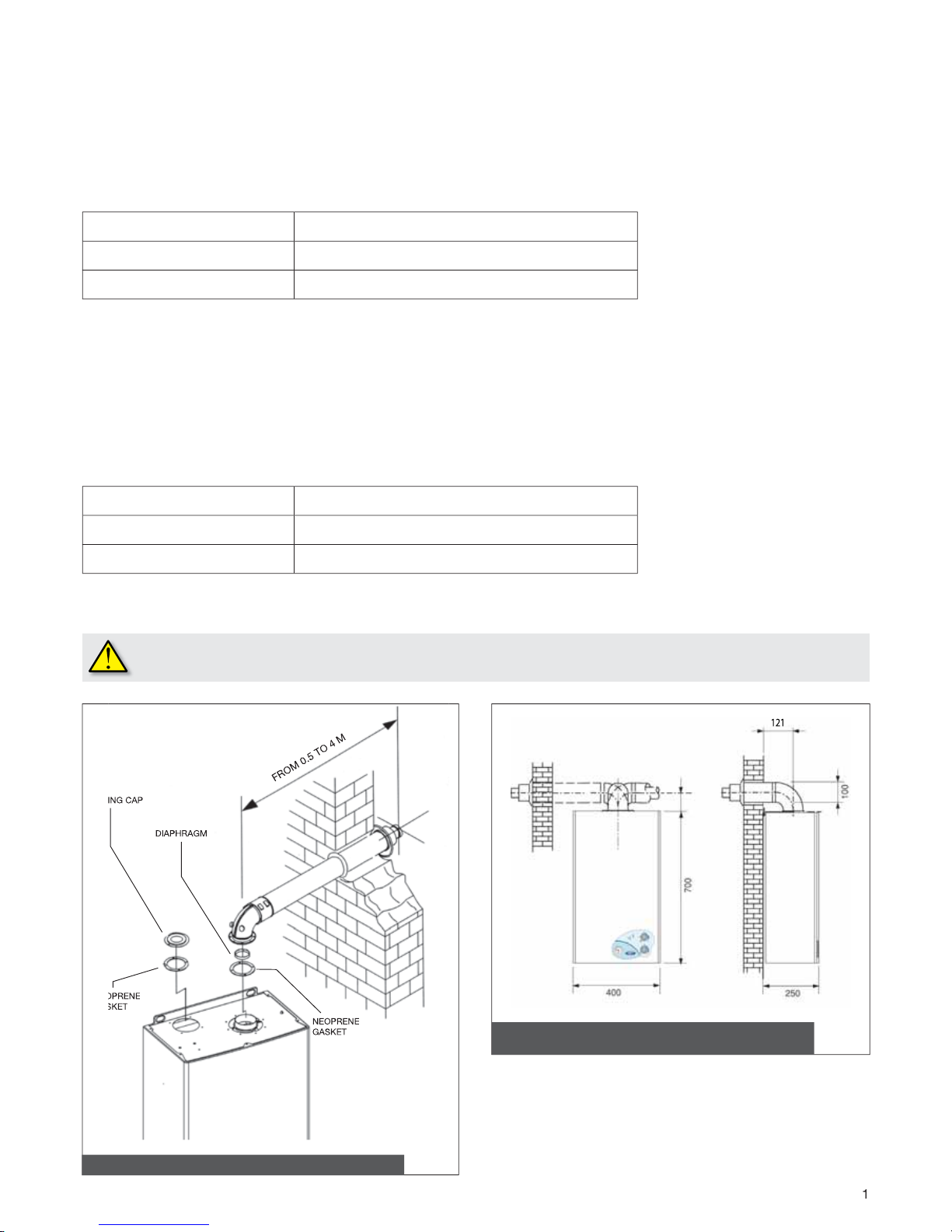
.2.6.2.2. Air intake and flue gas discharge system via 100/60 mm coaxial pipes
Type
C
12
inimum permissible length of horizontal coaxial pipes is 1 meter, not counting the very rst elbow connected to the boiler. Maximum
ermissible length of horizontal coaxial pipes is
meter, not counting the rst elbow connected to the boiler.
or each additional elbow maximum permissible length must be reduced by 1 meter. In addition to that, the duct is to have a 1%
lope toward the exit direction, in order to prevent rainwater entering it.
hoosing the applicable diaphragm supplied with the boiler (pic. 10
)
ipe length (m)
lue gas discharge diaphragm diameter (mm)
≤
≤
5
≤ L ≤
o diaphragm
the rst elbow from the boiler is not to be accounted for
ipe length (m
)
lue gas discharge diaphragm diameter (mm
)
1 ≤ L ≤
,
5
≤
≤
No diaphragm
Type
C
32
inimum permissible length for vertical coaxial pipes is 1 meter, equal to the length of the chimney.
aximum permissible length for vertical coaxial pipes is
meter, including the chimney.
or each additional elbow the maximum permissible length must be reduced by 1 meter.
hoosing the applicable diaphragm supplied with the boiler (pic. 10)
he above data are referred to air intake/flue gas exhaust systems which are implemented by means of smooth, rigid
anufacturer approved and supplied pipes.
Pic. 10 - Air intake/flue gas exhaust coaxial pipe system (CTFS)
Pic. 11 - Dimensions for connection to the air intake/flue gas
exhaust coaxial pipe system (CTFS)
EAL
NE
O
A
S
Page 22
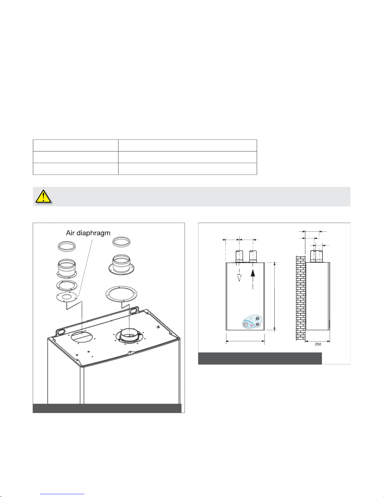
Pipe length (m
)
A
ir intake diaphragm diameter (mm)
,5 ≤ L ≤ 10
*
≤ L ≤
o diaphragm
* th
e
rst elbow from the boiler is not to be
accounted fo
r
3.2.6.2.3 Air intake and flue
g
as discharge system via 80/80 mm split pipes
C42 – C52 – C82 installation cate
g
ory
Air i
nta
ke
Minimum permissible length of air intake pipe is 1 meter.
Each wide radius 90° elbow (R=D) equals a 1 meter lon
g
pipe section.
Each narrow radius 90° elbow
(
R<D) equals a 1 meter long pipe section.
lue gas discharge
Minimum permissible length o
f
ue gas discharge pipe is 0,5 meter.
Each wide radius 90° elbow (R=D) in ue
g
as discharge equals a 1,5 meter long pipe section.
Each narrow radius 90° elbow (R<D) in ue
g
as discharge equals a
,5 meter long pipe section.
Choosin
g
the applicable diaphragm supplied with the boiler
7 diaphragm is supplied by the manufacturer in the optional air/ue gas split pipe kit
The above data are referred to air intake/flue gas exhaust systems which are implemented by means of smooth, rigid
manufacturer approved and supplied pipes
.
36,
5
6,5
80
Pic. 13 - Dimensions for connection to the air intake/flue gas
exhaust split pipe system (CTFS)
Pic. 12 - Air intake/flue gas exhaust split pipe system (CTFS)
,5
Page 23
23
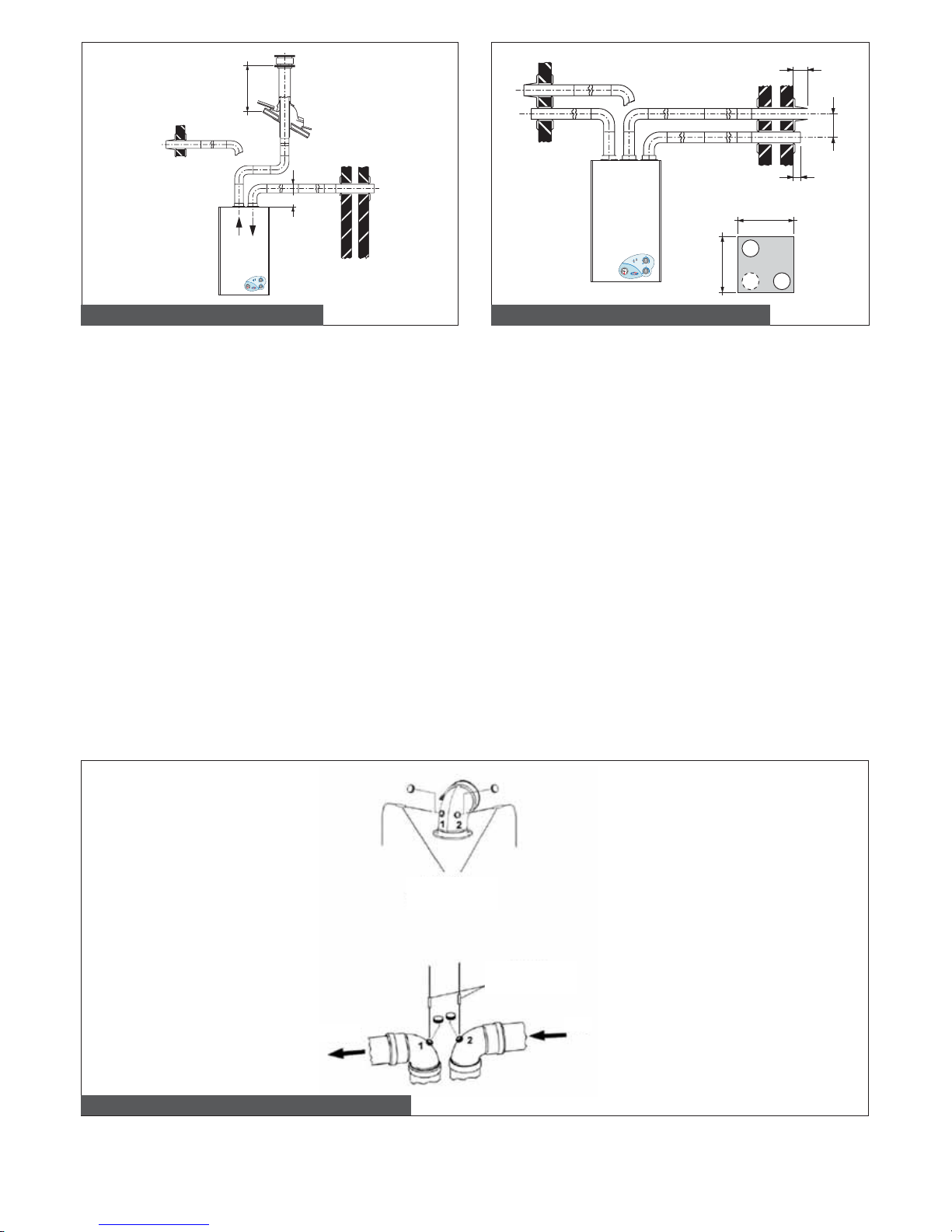
3.2.7 Checking combustion efficiency
In order to check combustion efciency, turn no. 5 knob fully clockwise and completely open one or two domestic hot water taps so
that the boiler will operate at max. output.
3.2.7.1 Coaxial pipe system
In order to verify combustion performance the following measurements must be implemented:
- Measure air temperature (from no. 1 opening shown in pic. 16A for sealed chamber boilers with prearranged openings).
- Measure ue gas temperature and CO
2
concentration (from no. 2 opening shown in pic. 16A for sealed chamber boilers with prear-
ranged openings).
Perform measurements while the boiler is operating at working temperature.
Once the above procedure is completed, close the domestic hot water taps and position no. 5 knob (pic. 1) to the desired setting.
3.2.7.2. Split pipe system
In order to determine combustion performance the following measurements must be implemented:
- Measure air temperature (from no. 2 opening shown in pic. 16B for sealed chamber boilers with prearranged openings).
- Measure ue gas temperature and CO
2
concentration (from no. 1 opening shown in pic. 16B for sealed chamber boilers with prear-
ranged openings).
Perform measurements while the boiler is operating at working temperature.
Once the above procedure is completed, close the domestic hot water taps and position no. 5 knob (pic. 1) to the desired setting.
* 500
H min. = 150 mm
0
1
3
6
5
42
bar
3
42
bar
135
250 min.
45
500 mm
500 mm
0
1
3
6
5
42
bar
3
42
bar
Pic. 14 – Split pipe installation samples
Pic. 15 - Additional split pipe installation samples
Pic. 16 - Sample areas for combustion efficiency measurements
A
B
Example no. 2
Example no. 1
Analyzer
probes
Analyzer
probes
Air
Flue gas
162 mm
Page 24
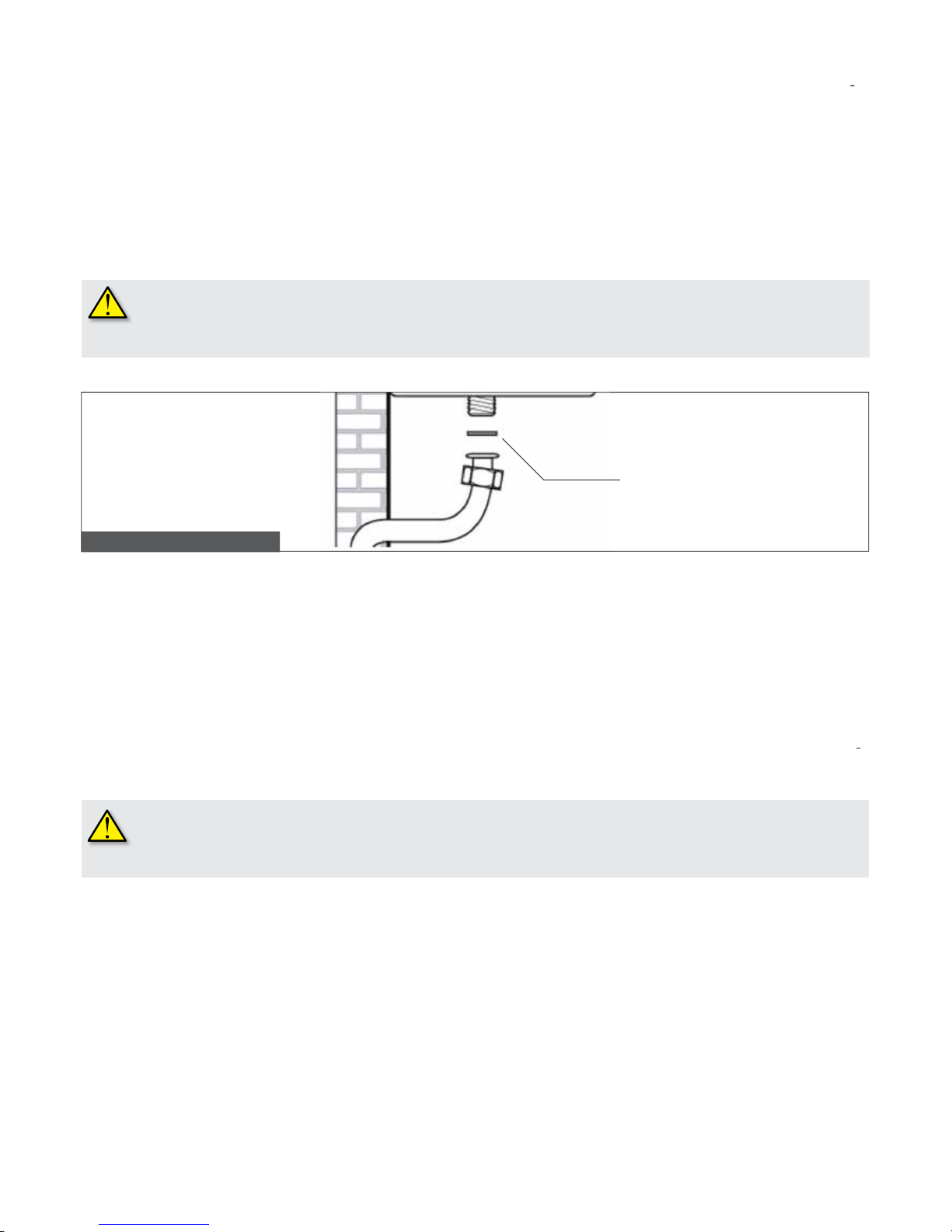
.2.8.
as mains connection
ross-section of gas supply pipe must be equal or greater than the boiler one. Cross-section size depends on its length, layout pat
ern, gas ow rate. It is therefore to be sized accordingly.
omply with installation standards enforced in the installation country. They are considered as an integral part of this booklet.
emember that before operate an internal gas distribution system and before connecting it to a meter, it must be checked for leaks.
n order to perform a leak test, operate according to the following indication:
The leak test is to be carried out before the pipes are covered. The leak test must not be carried out using ammable gas: use air
r nitrogen for this purpose.
Once gas is in the pipes, leak test by a naked ame is forbidden. Use specic products available on the market.
W
hen connecting a boiler to gas supply network the use of an appropriately sized and made gasket (pic. 17).
he boiler gas inlet thread configuration is not suitable for hemp, plastic tape or similarly made gaskets.
.2.9. Plumbing connections
rior to installing the boiler, the hydraulic system should be cleaned in order to remove impurities; they might be present in system
omponents and damage the pump or the heat exchanger.
ENTRAL HEATIN
G
H ow pipe and CH return pipe must be connected to their relevant / coupling on the boiler (see pic. 7).
hen sizing CH system pipes, bear in mind load losses caused by radiators, thermostatic valves, radiator gate valves, and the
on
uration of the system itself.
t is advisable to convey the discharge flow of boiler safety valve to the sewer system. Should that not be performed, and the
afety valve be activated, flooding of the room in which the boiler is installed may occur.
he manufacturer shall not be held responsible for any damage resulting from failure in observing the above mentioned
technical provision
.
MESTIC HOT WATER
HW ow pipe and water mains pipe must be connected to their relevant 1/ couplings C and F on the boiler (pic. 7).
ardness of water supplied to the boiler may increase heat exchanger cleaning and /or replacement frequency.
W
ARNIN
G
epending on hardness level of the water supplied, it might be necessary installing a suitable water treatment device for
omestic use and in compliance with applicable laws and standards.
W
ater treatment is always advisable when water supplied to the boiler is more than
20°
hard
.
W
ater supplied by commonly marketed water softeners, due to PH level induced in water, may not be compatible with some
omponents in system.
ASKE
T
Pic. 17 – Gas main connection
Page 25

.2.10.
wer mains connection
s
The boil
er is supplied with a three-poled power cable, already connected to the electronic board and it is provided with an anti-ruptu
e rming clamp.
The boile
r is to be connected to a
V-50Hz electric power supply.
omply with phase / neutral polarity sequence when power connecting the boiler.
nstallation standards must be complied with and they are considered as an integral part of this booklet.
A
n easily accessible two-poled switch, with a minimum
mm distance between contacts, is to be installed outside of the boiler. The
witch is to allow power supply cut-off in order to safely perform maintenance and service procedures.
ower supply to the boiler must be tted with a differential magnetic-thermal automatic switch of suitable disconnection capacity.
ectric power supply must be properly earthed.
T
he above mentioned safety measure must be veried. If in doubt, ask a qualied technician to thoroughly check the power network.
W
ARNIN
G
he manufacturer shall not be held responsible for any damage due to failure in grounding the system: gas,
ydraulic, or CH system pipes are not suitable for grounding power networks.
.2.11. Room thermostat connection (optional equipment
)
T
he boiler is designed to be connected to an ambient thermostat (not supplied with the boiler).
oom thermostat contacts must be properly sized in compliance with a load of 5 mA load at
Vdc.
A
mbient thermostat wiring must be connected to the relevant terminal board (see electric layout), after removing the
j
umper supplied as standard with the boiler.
he ambient thermostat wirings are NOT to be grouped together with power mains supply cables.
.3. Loading the system
nce all boiler connections have been completed, CH system can be lled.
T
he procedure is to be cautiously carried out, following each step:
open the air purging valves on all radiators and verify the boiler automatic valve operation;
gradually open the relevant loading tap (pic. ), checking all automatic air purging valves installed in the system properly work;
close all radiator air purging valves as soon as water starts coming out;
check boiler water pressure gauge not to exceed 1 / 1.
bars reading;
shut the loading tap and bleed any air out again, by opening the air bleeding valves on radiators;
start the boiler and bring the system to working temperature, stop the boiler and wait for the pump to stop, then repeat the air blee
ng procedures;
allow the system to cool and restore water pressure to 1 / 1.bars.
W
ARNIN
G
As f
ar as domestic heating systems treatment of water is concerned, in order to optimize performance and safety, to
reserve these conditions over time, to ensure long-lasting regular operation of aux
ili
ary equipment as well, and to minimize
nergy consumption, thereby integrating current local laws and standards it is advisable to use specific products that are
uitable for multi-metal plants.
W
ARNIN
G
he safety low water pressure switch will not give electric consensus to the burner turn on procedure when water pressure
s below 0,4/0,6 bar. CH water pressure is not to be less than 0,8/1 bar. Restore proper value as needed, via the loading tap
hich is provided as standard with the boiler (pic. 2). The procedure is to be followed while the system is cold. The pressure
auge fitted on the boiler control panel indicates the pressure in the CH system.
W
ARNIN
G
A
fter long inactivity of the boiler has its pump may be stuck. Before starting up the boiler, make sure that the pump is operati
e, by the following procedure:
remove the boiler casing;
unscrew the protective cap at the centre of the pump motor;
put a screwdriver into the hole and manually rotate the pump shaft clockwise;
once the unblocking operation is completed, screw the protective cap back on and check for water leaks.
Wh
en the protection cap is removed, some water may flow out. Before re-insta
lli
ng the boiler casing, make sure all internal
urfaces are dry.
Page 26

26
3.4 Starting the Boiler
3.4.1 Preliminary Checks
Before starting the boiler it is necessary to perform the following checks:
- ue gas discharge pipe and its terminal are installed in accordance to the instructions: when the boiler is running no products
generated by combustion are to leak from any gasket;
- power supplied to the boiler is 230 V – 50 Hz;
- the system is correctly loaded with water (water pressure gauge reading is 1 / 1,3 bars);
- all system pipes stopcocks are open;
- the gas supplied to the boiler corresponds to that for which the boiler is manufactured: convert the boiler to the available gas when
necessary ( see section 3.6 “Adaptation to other gases and burner adjustment”. The procedure is to be carried out by qualied
technical personnel;
- the gas supply stopcock is open;
- there are no gas leaks;
- the main switch external to the boiler is set to on;
- the 3 bar safety valve is not blocked;
- there are no water leaks;
- the pump is not blocked.
3.4.2. Switching on and switching off
In switching on and switching off the boiler, follow the “Instructions for the user”.
3.5. Wiring Diagram
0SCHEMOD11: Electronic pcb
M1-M10: Power Supply connector, TA
M13: Connector for tele-metering
M2-M12: Service connectors
E: Detection/ignition electrode
P: Circulation pump
V: Fan (TFS models only)
TF: Thermostat preventing ue gas overow
PV: Fan pressure switch (TFS models only)
DK: Low water pressure switch
SR: CH probe 10 Ohm A 25°C B = 3435
SS: DHW probe 10 Ohm A 25°C B = 3435
TA: Ambient thermostat (option)
CM1-CM2: Boiler type and gas type selection jumpers
FL: Flow sensor
VG: Gas valve
TL: Limit thermostat
Page 27

Pic. 18 – Wiring diagram
Page 28
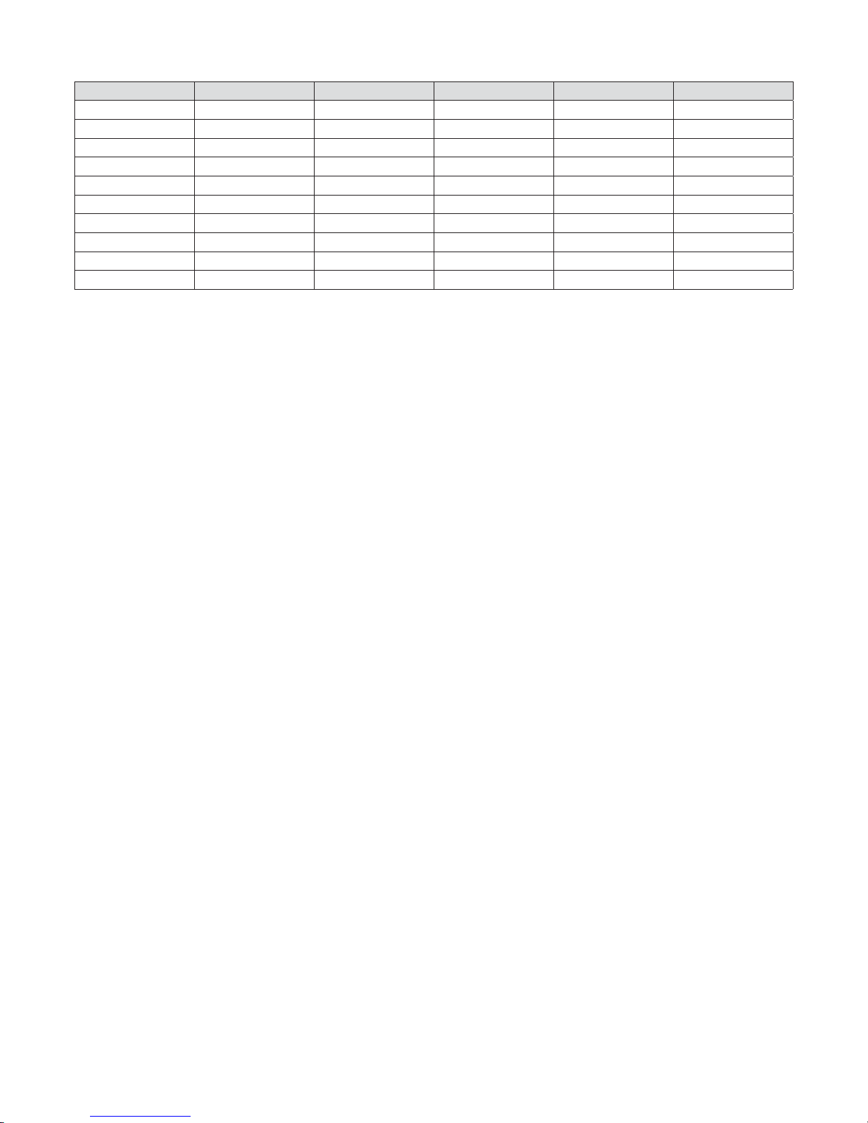
28
Relation between temperature (°C) and nominal resistance (Ohm) of CH probe SR and DHW probe SS.
T (°C) 02468
0 27203 24979 22959 21122 19451
10 17928 16539 15271 14113 13054
20 12084 11196 10382 9634 8948
30 8317 7736 7202 6709 6254
40 5835 5448 5090 4758 4452
50 4168 3904 3660 3433 3222
60 3026 2844 2674 2516 2369
70 2232 2104 1984 1872 1767
80 1670 1578 1492 1412 1336
90 1266 1199 1137 1079 1023
No. 7 chart – “Temperature - Nominal resistance” relation of temperature probes
Page 29
29
3.6 Adaptation to other gas types and burner adjustment
The boilers are manufactured for the gas specied upon order.
After sale transformation is to be exclusively implemented by qualied personnel, employing manufacturer designed accessories and
following the procedure and adjustment instructions for an accurate boiler setting-up.
Adapting the boiler from METHANE to LPG
- Remove the main burner;
- remove nozzles from main burner replacing them by new gas type correct diameter ones; WARNING! It is mandatory to install the
copper gaskets;
- re-install the main burner;
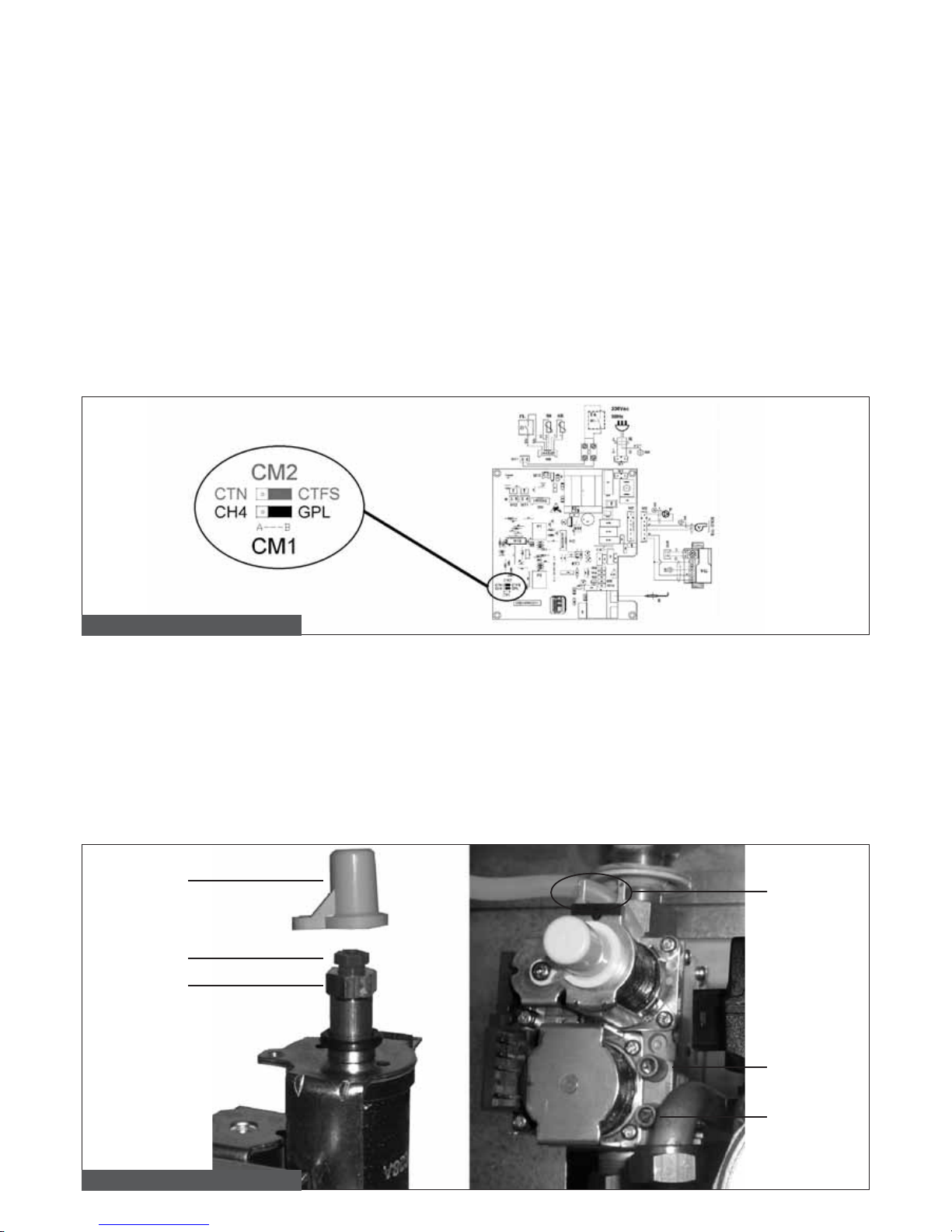
- on the electronic board, switch CM1 CH4-GPL jumper to GPL position (pic. 19).
Adapting the boiler from LPG to METHANE
- Remove the main burner;
- remove nozzles from main burner replacing them by new gas type correct diameter ones; WARNING! It is mandatory to install the
copper gaskets;
- re-install the main burner;
- on the electronic board, switch CM1 CH4-GPL jumper to CH4 position (pic. 19).
Pic. 19 – Methane – LPG selecting jumper
A) Maximum heat output adjustment
- Check gas mains supply and burner pressure (see no. 2 and no. 3 charts on page 14).
- remove plastic cap A (pic. 20), positioned on top on the coil of the modulating device, and protecting the screws of the pressure
adjusting device;
- connect a manometer to IN check (pic. 20), in order to verify the entering pressure and to the OUT check (pic. 20) in order to verify
the exiting pressure;
- fully turn clockwise no. 5 knob on the control panel (pic. 1), and open one or two domestic hot water taps for the boiler to operate at
max. output;
- turn CLOCKWISE the brass nut B for max. output adjustment (pic. 20) in order to increase nozzle pressure, and COUNTER-
CLOCKWISE in order to decrease nozzle pressure;
- for LPG operation, turn brass nut B fully CLOCKWISE.
Pic. 20 – Gas valve adjustment
D
OUT
IN
A
C
B
Page 30

Minimum heat output adjustment
Disconnect electric wiring from D modulation coil (pic.
;
turn the burner on and check minimum pressure value according to no.
and no.
charts on page 1
in order to adjust pressure, hold nut B still by means of a 100 mm tool, and turn plastic screw C CLOCKWISE to increase and
OUNTER-CLOCKWISE to decrease gas pressure;
re-connect electric wiring to modulation coil.
nal settings
Turn the boiler on and check its correct operation;
check again for correct minimum and maximum gas valve pressure of gas valve;
adjust as necessary;
install protective plastic cap A;
close gas pressure checks;
check for gas leaks.
. TTIN
G
B
ILER
.1 Preliminary checks
efore testing the boiler, it is recommended to carry out the following checks:
ue gas evacuation ducts and terminal are implemented according to instruction:
en the boiler is running
roducts generated by combustion are not to leak from gaskets;
power mains supply to boiler is
V – 50 Hz
;
the system is correctly loaded (water pressure on gauge 1 / 1,
bars);
all stopcocks in the system piping are open;
the gas type supplied to the boiler is in compliance with boiler specications In contrast, modify the boiler for the gas type available
see no.
6 section “ADAPTATION TO OTHER GAS TYPES AND BURNER ADJUSTMENT”);
the gas supply stopcock is open;
no gas leaks are detected;
the power switch, external to the boiler, is on;
the boiler
bar safety valve is not blocked;
the boiler pump is not blocked.
hould the boiler not be installed in compliance with current laws and standards, notify the system supervisor
nd do not test the boiler.
witching on and switching off
or boiler starting up and switching off procedure follow the “Instructions for the User”.
Page 31

. MAINTENANCE
outine boiler maintenance is to be scheduled according to current laws and regulations.
A
ppropriate boiler maintenance ensures efcient operation, environment preservation, and safety for people, animals and objects.
A
ll maintenance and repair procedures are to be carried out by qualied personnel.
T
he manufacturer recommends Customers to contact an authorized Service Centre for all maintenance and repair procedure as they
re best trained for the purpose.
efore implementing any maintenance procedure, involving replacement of components and/or cleaning inside
arts of boiler, disconnect electric power supply.
intenance sch
edule
outine maintenance schedule are to include the following:
check general integrity of the boiler;
check boiler and network gas supply for leakage;
check gas supply pressure to boiler;
check minimum and maximum gas pressures to boiler nozzles;
check boiler ignition sequence;
check boiler combustion parameters by way of ue gas analysis;
check ue gas system for integrity, good state of preservation, and leakage;
check draught stop device for good state of preservation (CTN);
check absence of ue gas reux in the room and correct ue gas discharge (CTN);
check operation of safety thermostat installed on the draught stop (CTN);
check air intake/ue gas pressure switch operation (CTFS);
check integrity of safety devices of the boiler in general;
check water leaks and oxidized areas on the boiler’s couplings;
check efciency of the system safety valve;
check expansion vessel loading pressure;
check water pressure switch efciency.
he following cleaning is to be done:
cleaning of boiler internal areas;
cleaning of gas nozzles;
cleaning of air intake and ue gas exhaust system (CTFS);
cleaning of draught stop device (CTN);
cleaning of ventilation grille in the boiler room (CTN);
cleaning of ue gas side of the heat exchanger.
hen checking the boiler for the very rst time, also verify:
boiler room suitability;
air vents in the boiler room (CTN);
diameter and length of ue gas system ducts;
boiler installation in accordance to this “Installation use and maintenance” manual instructions
;
hould the boiler not correctly operate, while not posing danger to people, animals or property, notify the
ystem supervisor both verbally and in writing.
Page 32
32
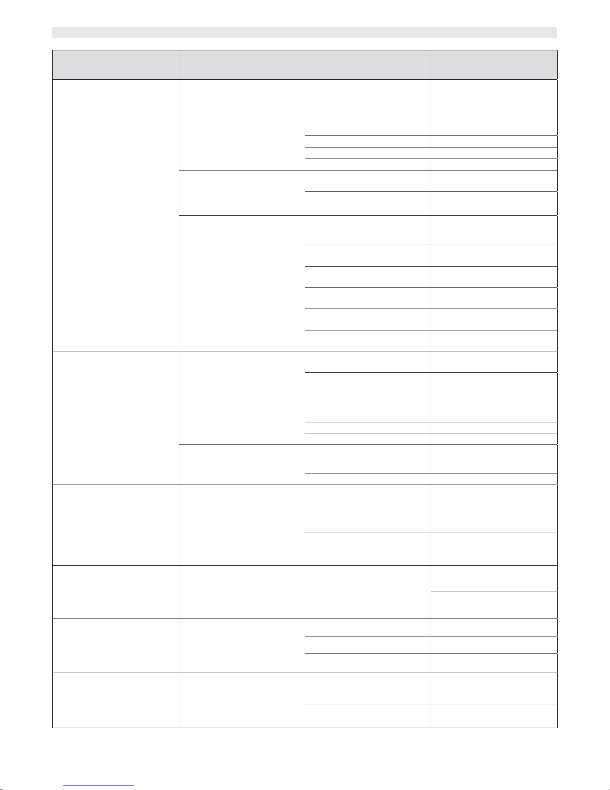
6. TROUBLESHOOTING
BOILER STATUS MALFUNCTION PROBABLE CAUSE SOLUTION
The boiler has shut down, and no. 2
led is on in red.
Turn no. 5 knob to reset position in
order to resume boiler operation.
Burner does not ignite
Gas supply failure
Check gas pressure
Check gas network stopcock or gas
network safety valve intervention
Gas valve has disconnected Reconnect it
Gas valve is faulty Replace it
PCB is faulty Replace it
Burner does not ignite: there is no
spark
Ignition/ame sensing electrode is
faulty
Replace the electrode
PCB does not ignite: it is faulty Replace PCB
Burner ignites for a few seconds
and goes off
PCB does not detect ame: inverted phase and neutral
Verify correct neutral and phase
connection sequence
Ignition/ame detection electrode
wire is interrupted
Connect ame detection electrode
wire or replace it
Ignition/ame detection electrode
is faulty
Replace electrode
PCB does not detect ame, it is
faulty
Replace PCB
Ignition heat input setting is too low Increase it
Minimum heat input in not set
correctly
Check burner setting
The boiler has shut down and no. 1
led is on in yellow.
Turn no. 5 knob to reset position in
order to resume boiler operation.
Air intake/ue gas exhaust pressure
switch is not operating (CTFS)
Air intake/ue gas exhaust pressure
switch is faulty
Check Air intake/ue gas pressure
switch: replace it if faulty
The silicone pipes of switch are
disconnected or damaged
Connect or replace silicone pipes
Air intake or ue gas discharge ow
is nor correct
Check air intake or ue gas
discharge
Fan is faulty Replace it
PCB is faulty Replace it
Flue gas thermostat has shut the
boiler down ( CTN )
Air intake or ue gas discharge
system is weak
Check air intake or ue gas discharge system and vent grilles in the
boiler room
Flue gas thermostat is faulty Replace it
The boiler has shut down and no. 1
led is on in red.
The boiler will automatically resume
operation after 10 seconds or turning no. 5 knob to reset position.
The safety thermostat has shut
boiler down
CH water does not ow in the
system: pipes might be clogged,
thermostatic valves might have
shut, system stopcocks might be
closed
Check CH system
Pump is blocked or faulty Check the pump
No. 1 led is on in red.
The boiler will resume operation
as soon as the malfunction is
corrected.
CH water ow temperature exceeded 85°C
Water ow in the system is not
adequate
Check the pump
Check CH system
No. 1 led is on in yellow.
The boiler will automatically resume
operation as soon as the malfunction is corrected.
CH system water pressure is low
The system is leaking Check CH system
Water pressure switch is disconnected
Reconnect it
Water pressure switch is not operating: it is faulty
Replace it
No. 1 led is ashing yellow and red.
The boiler will automatically resume
operation as soon as the malfunction is corrected.
CH ow is not working
CH probe is disconnected Reconnect it
CH probe is faulty Replace it
Page 33

33
BOILER STATUS MALFUNCTION PROBABLE CAUSE SOLUTION
No. 1 led is ashing green and red.
The boiler will automatically resume
operation as soon as the malfunction is corrected.
DHW probe is not working
DHW probe is disconnected Reconnect it
DHW probe is faulty Replace it
Boiler is not supplying DHW
DHW ow meter is not working
System insufcient pressure or
ow rate
Check DHW system
Check DHW ow meter lter
DHW ow meter sensor is faulty or
disconnected
Replace or reconnect it
DHW ow meter sensor is blocked Replace it
No. 1 led is ashing green.
The boiler will automatically resume
operation as soon as the malfunction is corrected.
Gas valve modulation coil is not
working
PCB and gas valve link is disconnected or faulty
Check connection to the gas valve
Gas valve modulation coil is faulty Replace gas valve modulation coil
Page 34

34
Page 35

35
Page 36

0LIBMUEN09
Uff. Pubblicità Fondital IST 04 C 167 - 02 Novembre 2006 (11/2006)
The manufacturer reserves the right to implement any necessary and/or useful
variation to products, without modifying fundamental characteristics.
Fondital S.p.A.
Via Mocenigo, 123
25078 VESTONE (Brescia) Italy
Tel. +39 0365 878.31 - Fax +39 0365 596.257
e mail: [email protected]
www.fondital.it
 Loading...