

Page 1
The Trolley™ E-Class
Personal Monitor Arm System
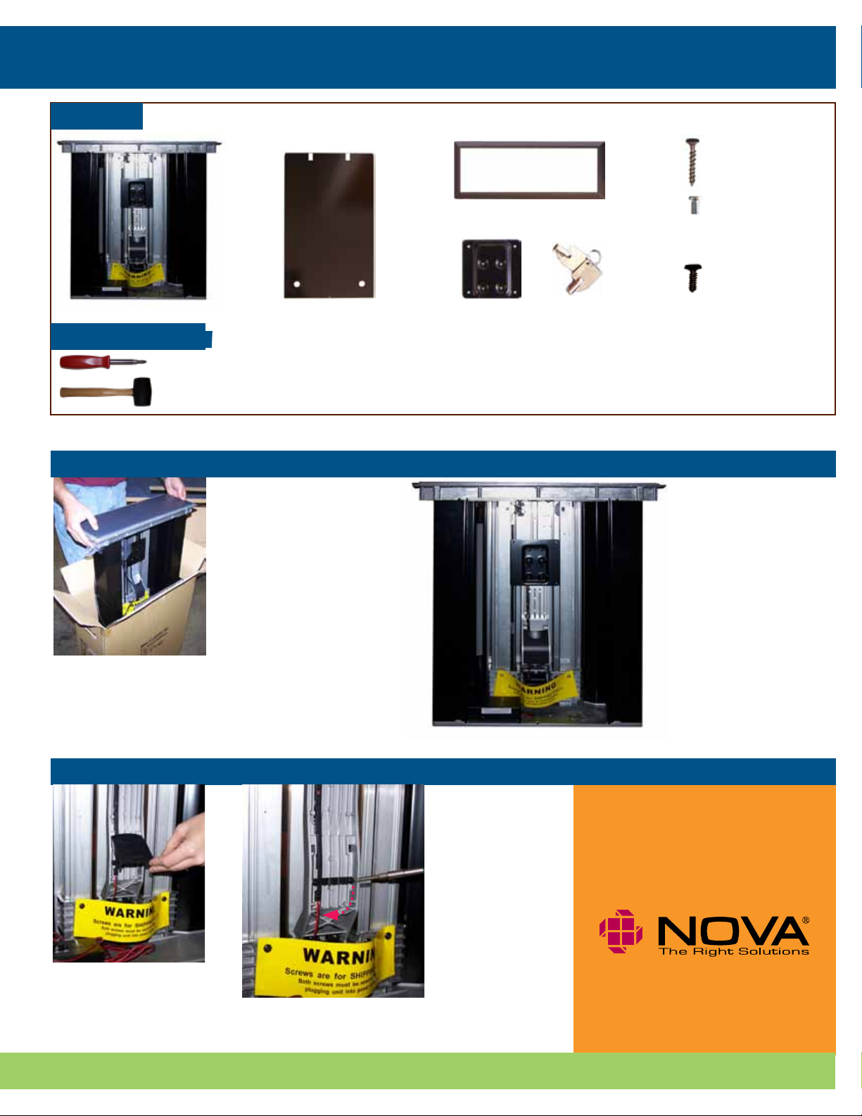
Parts List
Installation & Operating Instructions
Qty. 9
#6 x 3/4” screws
Qty. 4
Monitor screws
Phillips pan head
M4, length: 6mm
Qty. 2
Wire management
grommet screws
Phillips pan head
3mm, self-threading
screw, length: 10mm
The Trolley™ E-Class Removable Metal
Front Cover
Tools (not included)
Phillips Screwdriver
Power screwdriver may also be used,
if desired.
Rubber Mallet
(Ships with Flush Mount or Surface Mount)
75mm VESA
Trim Ring
Keys
Plate
(100mm
VESA Plate
Installed)
Note: Do NOT connect the Trolley E-Class to power source until Step 4.
Step 1:
1b. Place Trolley E-Class
in its upright, vertical
position with the open
interior side facing
you.
a.
1a. Remove Trolley E-Class
and parts from shipping
box.
Step 2:
a.
2a. With arm in down
position, remove black
cable management
cover.
b.
2b. Remove right
screw from cable
retention
clip on cable management channel. Then
loosen left screw
and rotate clip
downward.
b.
Need assistance? Call 1-800-730-6682 for NOVA Solutions Customer Support Page 1 of 4
Page 2
The Trolley
5c. If 75mm VESA plate required,
Personal Monitor Arm System
Step 3:
™
E-Class
Installation & Operating Instructions
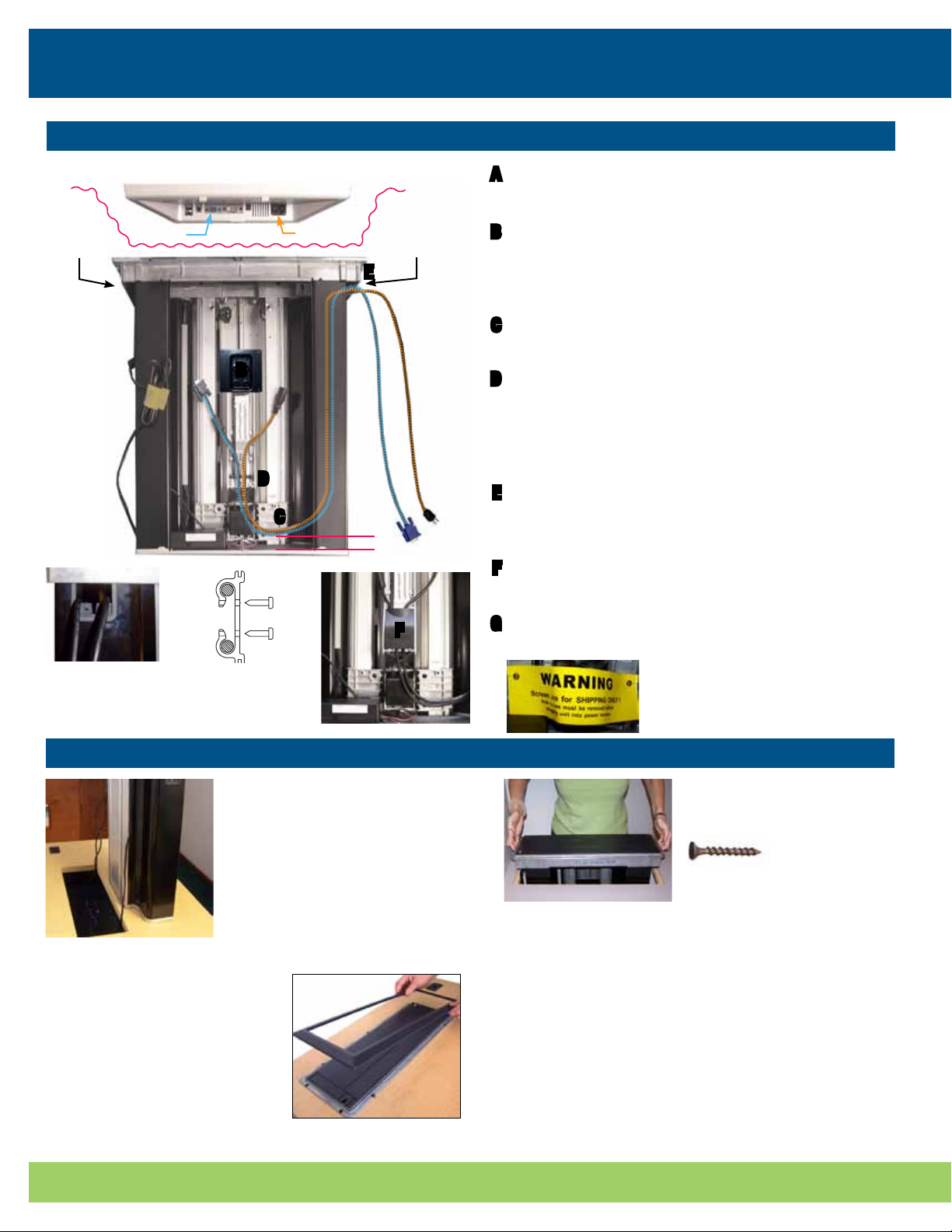
Flat panel monitor (bottom view. Dell monitor pictured here. Other brands may vary.
Video Port Power Port
Side Grommet
A
B
D
C
Side Grommet
E
1”
A
B
C
Step 7:
D
E
F
Feed monitor video and power cables through the
grommets on either side of The Trolley.
Align other end of video and power cables with ports on
monitor. Position the end of the cables even with the
center of the VESA plate on monitor arm. These cords
may need adjustment in Step 6a.
Leave about 1” of clearance between the video/power
cables and the bottom of The Trolley E-Class.
Place video/power cables in two center wire
management channels on monitor arm. Bring wire
clip (rotated downward in Step 3) back up over wires,
aligning right side over screw hole. Tighten left screw,
then reinstall and tighten right screw.
Place video and power cables in wire retention clamps
on side grommet. Secure screws in grommet. Make
sure all wires are clear of screw hole. See figs. 1 & 2.
Reinstall black cable management cover that was
removed in Step 2.
fig. 1 - Side grommet
with wire retention
clamps
fig. 2 - Top view
of wire retention
clamps
Step 4:
4a. With the open side of
The Trolley facing the user
side of the desk, place Trolley
on work surface adjacent to
work surface cutout.
Feed video and power cables
a.
through cutout.
4c. Using the palm of your hand
or a soft rubber mallet and a
block of wood, push or gently
tap the trim ring into place.
Start at one end and work your
way to the other. The NOVA logo
should be facing the user.
G
F
Completely remove two shipping screws indicated
by the yellow warning label.
Warning: After screws are removed and
before monitor is installed, arm may move
upward. If this happens, it should be
stopped by holding it with your hand.
4b. Lower Trolley into the
cutout and secure with nine
(#6 x 3/4”) screws provided.
Note: At this point, you can plug-in power
b.
and activate Trolley to open door and grip
the inside of unit while lowering into cutout, but unit must be in “Install Mode” to
allow door to stay open.
Make sure the PCU switch is in “Install Mode” before
completing Step 4d. Refer to Step 7a for location of PCU.
4d. Plug Trolley into power source. Insert and turn the key
to illuminate blue LED light. Wait 5 seconds to activate, then
push button and hold to open door and raise Trolley arm. The
power control module in the bottom of the Trolley housing is
normally shipped in “Install Mode.” The green LED does not
light when in “Install Mode.”
c.
Note: “Install Mode” only allows upward motion of arm and
access door will remain open.
Page 3

The Trolley™ E-Class
5c. If 75mm VESA plate required,
Personal Monitor Arm System
Step 5:
Installation & Operating Instructions
a.
5a. Select appropriate size VESA
plate for your monitor.
(100mm VESA plate installed)
Note: Once installed, the bottom of your
monitor should be 1 1/2” to 2” above the closed
Trolley door.
c.
remove four black screws on 100mm
VESA plate. Attach 75mm VESA plate
in correct position for monitor size.
5b. VESA plates can be detached and rotated to ensure a monitor
height clearance of 1 1/2” - 2” above closed Trolley door.
b.
5c. Depending on the depth of your monitor’s VESA plate mounting
area and/or the thickness of your monitor, different screw holes
can be used to adjust the space between the monitor and The
Trolley arm.
Using the flush screw holes
increases the space between the
monitor and the arm.
Using the indented screw holes
decreases the space between the
monitor and the arm.
Step 6:
6a. Attach the video and power cables
to your monitor. Allow enough slack in
cables for easy tilting of monitor, but do
not allow them to touch the work surface
or interfere with Trolley operation.
a. b.
Step 7:
a.
7a. Locate the power control
module at the bottom of The
Trolley E-Class and move the
switch to the right to “Operation
Mode.” The green LED will light.
Cables should allow for monitor tilt, but
should not touch work surface.
b.
7b. Push “Down” button for a few
seconds to activate unit. Once
the monitor is completely lowered
into the Trolley, the door will close
automatically.
Note: Pushing “Up” button will close door.
6b. Attach monitor
to VESA plate with
four monitor screws
provided.
Note: It may be helpful to have
another person assist in holding the monitor while attaching
it to the VESA plate.
7c. Remove the small
screw located at the bottom of Trolley (Ref. H). Slide
the top end of the removable metal front cover
into the upper front cover
slot. Note: Top of front
cover must slide inside the
groove of the top structure.
H
Slide bottom of cover into
c.
Trolley aligning with screw
hole. Reinstall the screw.
Need assistance? Call 1-800-730-6682 for NOVA Solutions Customer Support Page 3 of 4 Page 2 of 4 Need assistance? Call 1-800-730-6682 for NOVA Solutions Customer Support
Page 4

The Trolley™ E-Class
Personal Monitor Arm System
Intelligent Motion Technology
Overview
™
The Trolley
E-Class includes Intelligent Motion Technology.™ This feature reduces the risk of accidental damage and personal injury. Utilizing information from various different sensors, Intelligent Motion Technology™ continually monitors the Trolley’s operational
status and delivers information to the power control module.
If conditions create a “conflict” within The Trolley’s programming, the system will automatically take action to reduce damage or
injury. See below for some common operational conditions and how to resume normal operation.
Operational Guidelines
™
Power Failure
• In the event of a power failure during operation...
Operational Guidelines
Obstruction During Upward Motion
• If someone or something obstructs the upward
motion of the monitor (such as someone leaning
on or pushing down on the monitor)...
Monitor is Tilted During Operation
• If the monitor is moved out of vertical alignment
while Trolley is operating...
Access Door is Obstructed or Jammed
• If The Trolley senses an obstruction in the path of
the access door...
Operational StatusCondition
Unit will STOP
Unit will STOP
Unit will STOP
Unit will STOP
To Resume Operation...
Once power is restored, push the “Up” button to resume
normal operation. The Trolley will return to the “Up” position.
Once obstruction is cleared, push the “Up” button to resume
normal operation. The Trolley will return to the “Up” position.
Move monitor to fully vertical position. Push “Up” to resume
normal operation.
Note: The Trolley will not operate when the monitor is tilted.
The Trolley’s “Over-current Sensor” will stop the unit from
operating until the door obstruction is removed. Once the
path is clear, push either “Up” or “Down” buttons to resume
normal operation.
Page 4 of 4
For more information on installation and operation of The Trolley™ E-Class,
please contact Customer Support at 800-730-6682 or support@novasolutionsinc.com
© 2009, NOVA Solutions, Inc.
NOVA products are protected by various U.S. and foreign patents issued and/or pending.
INST_TR_E_01_11/10/09
 Loading...