

Page 1
The Trolley™
Monitor lift System
s
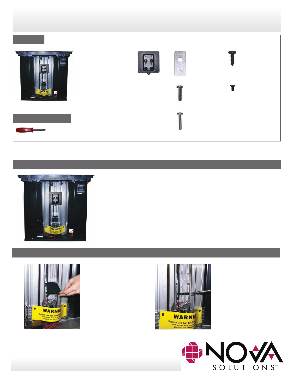
Parts List
Installation & Operating Instructions
The Trolley™ Removable Metal
Tools (not included)
Phillips Screwdriver
Power screwdriver may also be used.
Note: Do not connect the Trolley™ to power source until step 4
Step 1:
Front Cover
100mm VESA
Plate
Qty. 4
Locking Plates
Qty. 4
10-24 x 3/4
Locking Plate Screw,
Shorter
Qty. 4
8-32 x 7/8
Locking Plate Screw,
Longer
Qty. 1
Pan head #10 x 5/8
Black Screw for
front cover
Qty. 1
4mm x 0.7
Anti-tilt screw, black
(Pre-installed in
Tounge of VESA Plate
b.
Step 2:
a.
1a. Remove Trolley™ and parts from shipping box.
1b. Place Trolley™ in it’s upright, vertical position
with the open interior side facing you.
2a. With arm in down
position, remove
black cable
management
cover.
2b. Remove right
screw from cable
retention clip on
cable management
channel. Then
loosen left screw
and rotate clip
downward.
Need assistance? Call 1-800-730-6682 for NOVA Solutions Customer Support
Page 2
The Trolley™
Monitor lift System
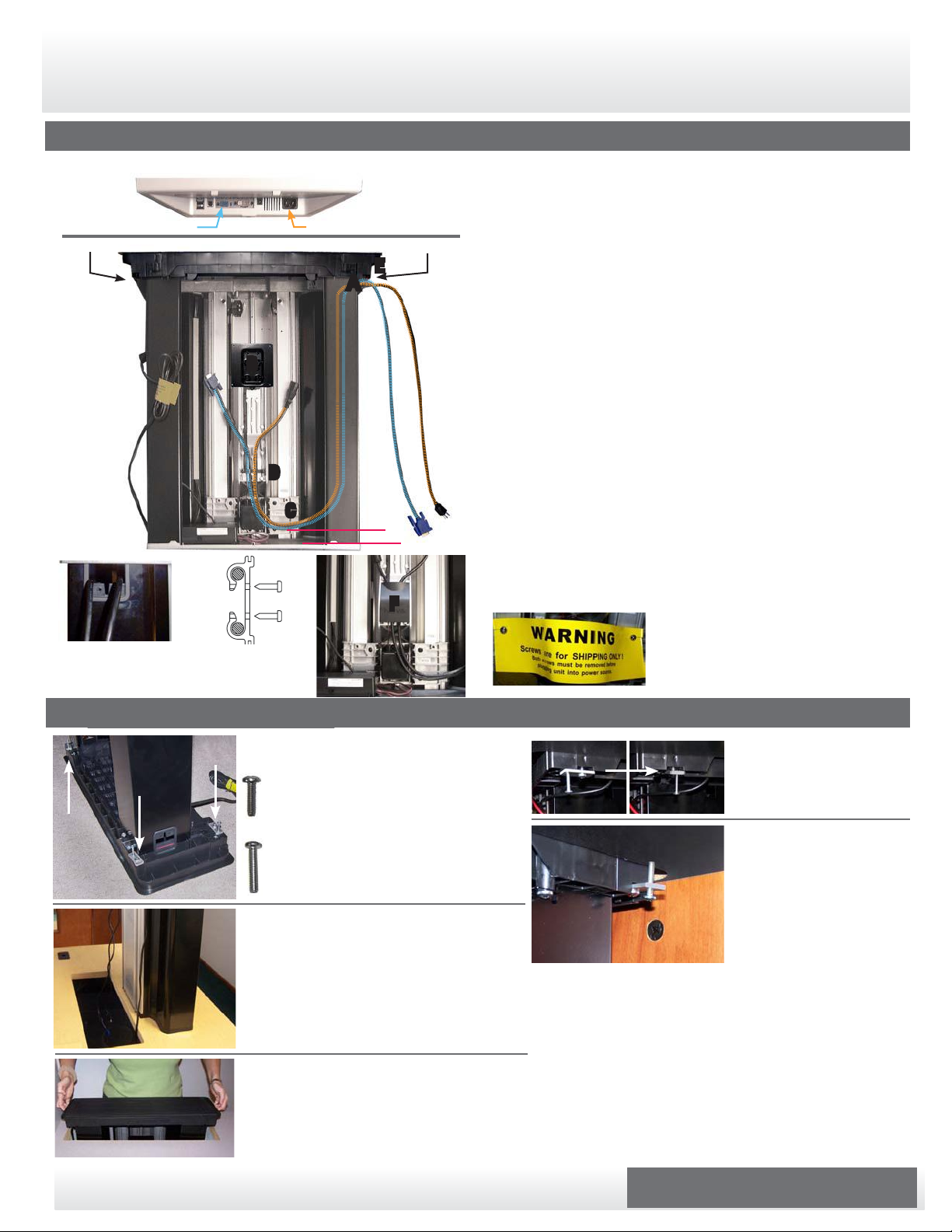
Step 3:
Installation & Operating Instructions
Flat panel monitor (bottom view). Dell monitor pictured here. Other brands may vary.
Video Port
Side Grommet
Power Port
Side Grommet
E
A
A
B
D
C
1”
F
Fig. 1 - Side grommet
with wire retention
clamps
Fig. 2 - Top view
of wire retention
clamps
A. Feed monitor video and power cables through the grommets
on either side of the Trolley™.
B. Align other end of video & power cables with ports on monitor.
Position the end of the cables even with the center of the VESA
plate on monitor arm. These cords may need adjustment in step
6b.
C. Leave about 1” of clearance between the video/power cables
and the bottom of the Trolley™.
D. Place video/power cables in two center wire management
channels on monitor arm. Bring wire clip (rotated downward
in step 2b) back up over wires, aligning right side over screw
hole. Tighten left screw, then reinstall and tighten right screw.
E. Place video and power cables in wire retention clamps on side
grommet. Secure screws in grommet. Make sure all wires are
clear of screw hole. See figures 1 & 2.
F. Reinstall black cable management cover that was removed in
step 2.
G. Completely remove two shipping screws indicated by the
yellow warning label.
WARNING: After screws are removed and
before monitor is installed, arm may move
upward. If this happens, it should be
stopped by holding it with your hand.
Step 4:
4a. Position locking plates as shown, over
four threaded hole locations in Trolley™.
Use (4) shorter 10-24 x 3/4 locking
plate screws and tighten locking plates.
Insert (4) longer locking plate screws into
second locking plate hole. Finish
tightening in Step 4e.
a.
4b. With the open side of the Trolley™
facing the user side of the desk, place
Trolley™ on work surface adjacent to
work surface cutout.
Feed video and power cables through
cutout.
b.
4c. Lower Trolley™ into the cutout.
c.
4d. Turn locking tabs 90°.
d.
4e. Tighten locking plate
screws to worksurface
tight enough to
prevent the Trolley™
from shifting.
e.
4f. Plug the Trolley™ into power source. Wait 5 seconds to
activate, then push the UP button to open door and
raise the Trolley™ arm.
Need assistance? Call 1-800-730-6682 for NOVA Solutions Customer Support
Page 2 of 4
Page 3
The Trolley™
Monitor lift System
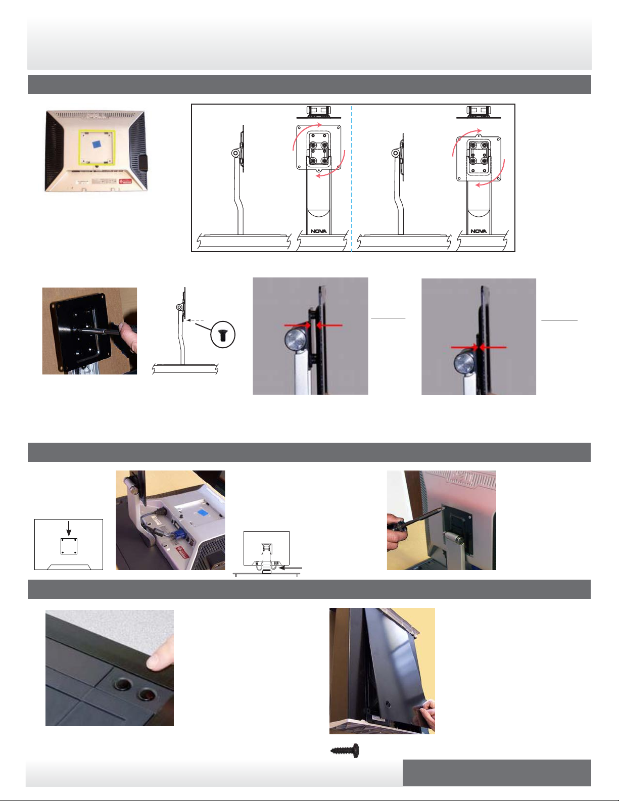
Step 5:
Installation & Operating Instructions
a.
5a. Confirm appropriate size VESA
plate for your monitor.
(100mm VESA plate installed)
Note: Once installed, the bottom of your
monitor should be 1 1/2” to 2” above the
closed Trolley™ door.
Optional: If 75mm VESA
plate is required, contact
Customer Service at
1-800-730-6682
Note: To enable the
adjustability of the
monitor, remove the
Anit-tilt Screw (G) witch
secures the VESA plate to
b.
arm.
(G)
5b. VESA plates
can be detached
and rotated to
ensure a monitor
height clearance
of 1 1/2” to 2”
above the closed
Trolley™ door.
c.
c.
5c. Depending on the depth of your monitor’s VESA plate mounting area and/or the
thickness of your monitor, different screw holes can be used to adjust the space
between the monitor and the Trolley™ arm.
Using the
flush screw
holes
increases
the space
between
the monitor
and the
arm.
Using the
indented
screw holes
decreases
the space
between
the monitor
and the
arm.
Step 6:
6a. Remove the four
screws located
on back of
monitor.
a.
Step 7:
a.
6b. Attach the video and power cables to
6b.
your monitor. Allow enough slack in
cables for easy tilting of monitor, but
do not allow them to touch the work
surface or interfere with Trolley
operation
b.
7a. Push “Down” button for a
few seconds to activate
unit. Once the monitor is
completely lowered into
the Trolley™, the door will
close automatically.
Note: Pushing the “Up” button
will close the door.
Note: cables should
allow for monitor tilt,
but should not touch
work surface
b.
(H) Pan head #10 x 5/8 Black Screw for front cover
6c. Attach monitor to
.
VESA plate using
the four removed
monitor screws.
Note: It may be helpful to
have another person assist in
holding the monitor while
c.
7b. Remove the black screw located
(H)
at the bottom of the Trolley™
(H). Slide the top end of the
removable metal front cover
into the upper front cover slot.
Note: Top of front cover must slide
inside the groove of the top structure.
Slide bottom of cover into
Trolley™ aligning with screw
hole. Reinstall the screw.
attaching it to the VESA
plate.
Need assistance? Call 1-800-730-6682 for NOVA Solutions Customer Support
Page 3 of 4
Page 4

The Trolley™
Monitor lift System
Installation & Operating Instructions
Overview
The Trolley™ EXL includes Intelligent Motion Technology™. This feature reduces the risk of accidental
damage and personal injury. Utilizing information from various different sensors, Intelligent Motion
Technology™ continually monitors the Trolley’s™ opperational status and delivers information to the
power control module.
If conditions create a “conflict” within the Trolley’s™ programming, the system will automatically take
action to reduce damage or injury. See below for some common operational conditions and how to
resume normal operation.
Operational Guidelines / Troubleshooting
Condition
Power Failure
• In the event of a power failure during operation...
Obstruction During Upward Motion
• If someone or something obstructs the upward
motion of the monitor (such as someone leaning
on or pushing down on the monitor)...
Monitor is Tilted During Operation
• If the monitor is moved out of vertical alignment
while Trolley™ is operating...
Opperational
Status
Unit will STOP
Unit will STOP
Unit will STOP
To Resume Opperation...
Once power is restored, push the “Up” button to
resume normal operation. The Trolley™ will return to
the “Up” postion.
Once obstruction is cleared, push the “Up” button to
resume normal operation. The Trolley™ will return to
the “Up” postion.
Move monitor to fully vertical position. Push “Up” to
resume normal operation.
Note: The Trolley™ will not operate when the monitor
is tilted
Access Door is Obstructed or Jammed
• If the Trolley™ senses an obstruction in the path
of the access door...
Unit will STOP
The Trolley’s™ “Over-current Sensor” will stop the unit
from operating until the door obstruction is removed.
Once the path is clear, push either “Up” or “Down”
buttons to resume normal operation.
For more information on installation and operation of the Trolley™ EXL,
please contact NOVA at 800-730-6682 or sales@novasolutionsinc.com
Need assistance? Call 1-800-730-6682 for NOVA Solutions Customer Support
Page 4 of 4
Trolley_Retro_Inst_05/19
Page 5

Retro Trolley Install Instructions - Dual Trolley Addendum
Page 6

Fig. A
Fig. A
After placing Retro Dual Trolley in worksurface cutout,
remove these two screws to install Center Locking Plates.
(See Fig. B)
Page 7

Locking Plate Screw
Locking Plate Screw
Note: Center Locking Plates are slightly
different than normal Locking Plates.
The through-hole is slightly larger and
the overall length is shorter.
Center Locking Plate
Fig. B
Attach Center Locking Plates using screws removed in Fig. A.
Tighten Locking Plate Screw to underside of worksurface to
secure Retro Dual Trolley.
Page 8

Fig. C
Once Retro Dual Trolley is secured in place,
connect the two Black USB cables on the
back side of the Retro Dual Trolley.
 Loading...