

Page 1

52920 EN
Only
Stat Prole PRIME
®
CCS Analyzer
Instructions for Use
Manual
Page 2

Page 3

Nova Prime CCS Analyzer Quick Start Guide
Conrm the analyzer is
1
Ready for analysis.
Displays Ready, desired
test menu shows no Orange
Icons.
Login if necessary. Press
2
the Login icon then enter
or scan your User ID and
Password.
Select the Sample Container and the Panel.
3
Prepare the sample for analysis then press
4
to extend the sample probe.
Position the sample
5
over the sample probe
then press to
aspirate the sample.
Enter any additional
6
patient or sample
information needed
while the analysis is
completed.
Review results.
7
Page 4

LEVEL
REP
EC
SN
NOVA BIOMEDICAL SYMBOL DIRECTORY
In vitro diagnostic
medical device
Device for near-patient testing
Caution
Consult Instructions for Use
Biological risk
Catalog number
Manufactured by
Control
Level
YYYY - MM - DD
Only
Batch code
Serial number
Temperature limitation
Use by date
Electronic Waste
Authorized representative
in the European Commission
Laser radiation:
Do not stare into beam
Prescription use only
Page 5

Prime CCS Instructions for Use Manual
Revision History
PN52920 Prime CCS Instructions for Use Manual
Rev Release Description
H 05 – 2022 Update to meet IVDR requirements
J 01 – 2023 Hazardous Waste Disposal Advisory
Page 6

Preface
Ordering Information
The Stat Prole PRIME CCS Analyzer Instructions for Use Manual
can be ordered from Nova Biomedical Order Services. Call, fax, or
write to:
Nova Biomedical Corporation Phone: 1-800-458-5813
200 Prospect Street FAX: 1-781-893-6998
Waltham, MA 02454 (in the USA)
USA
The Stat Prole Prime CCS analyzer is manufactured in the USA
by Nova Biomedical Corporation.
REP
EC
Nova Biomedical GmbH Phone: + 49 (0) 61054505-0
Hessenring 13A, Geb. G FAX: + 49 (0) 61054505-37
64546 Mörfelden-Walldorf
Germany
Authorized Representative
+1-781-891-9718
(outside the USA)
Web: www.novabiomedical.com
Trademark
Stat Prole is a registered Trademark of Nova Biomedical
Corporation.
Stat Prole Prime is a registered Trademark of Nova Biomedical
Corporation.
®
®
Copyright
Printed in the U.S.A. Copyright 2023, Nova Biomedical Corporation,
Waltham, MA 02454.
i
Page 7

Prime CCS Instructions for Use Manual
T echnical Assistance
For technical assistance inside the United States, call Nova Biomedical
Technical Services:
1-800-545-NOVA (6682)
1-781-894-0800
FAX: 1-781-894-0585
For technical assistance outside the United States, call your local Nova
subsidiary or authorized distributor.
Nova Biomedical recommends users report any serious incidents/
adverse events to Nova Biomedical or Nova Biomedical’s Authorized
Representative, as well as to local Competent Authorities as required.
Nova Biomedical Canada Ltd.
17-2900 Argentia Road
Mississauga, Ontario L5N 7X9
Canada
Tel: 1 905 567 7700
Toll Free: 800 263 5999
Fax: 1 905 567 5496
ca-info@novabio.com
Nova Biomedical France
Parc Technopolis
Bât. Sigma 3 Avenue du Canada
91940 Les Ulis Courtaboeuf
France
Tel: (33) 1-64 86 11 74
Fax: (33) 1-64 46 24 03
Nova Biomedical UK
Innovation House
Aston Lane South
Runcorn, Cheshire,
WA7 3FY, UK
Tel: + 44 1928 704040
Fax: + 44 1928 796792
uk-info@novabio.com
Nova Biomedical Iberia, S.L.
c/Vic 17, Planta 3A
08173 Sant Cugat del Vallès
Barcelona
Spain
Tel: +34 935531173
es-info@novabio.com
or pt-info@novabio.com
Nova Biomedical Italia Srl
Via Como 19
20045 Lainate Milano
Italy
Tel: +39 02 87070041
Fax: +39 02 87071482
it-info@novabio.com
Nova Biomedical GmbH
Hessenring 13A, Geb. G
64546 Mörfelden-Walldorf
Germany
Tel: + 49 6105 4505-0
Fax: + 49 6105 4505-37
de-info@novabio.com
Nova Biomedical Benelux BV
Europalaan 4
5232 BC Den Bosch
The Netherlands
Tel: +31 (0) 733032701
NL-info@novabio.com
or BE-info@novabio.com
Nova Biomedical Switzerland
GmbH
Herostrasse 7
8048 Zürich
Switzerland
Tel: +41-41-521-6655
Fax: +41-41-521-6656
e-mail: ch-info@novabio.com
Nova Biomedical Brasil
Rua Massena, 107
Jardim Canadá
Nova Lima – MG Cep: 34007-746
Brasil
Tel: (55) 31 3360-2500
E-mail: sac@novabiomedical.com.br
Nova Biomedical KK
Harumi Island
Triton Square Ofce Tower X 7F
1-8-10 Harumi, Chuo-ku
Tokyo 104-6007
Japan
Tel: 03-5144-4144
Fax: 03-5144-4177
jp-info@novabio.com
ii
Page 8

Contents
1 Introduction 1-1
1.1 About This Manual .....................................................................1-1
1.2 Safety .........................................................................................1-2
1.3 Installation and Use ...................................................................1-5
1.4 Requirements ............................................................................1-5
1.5 Cleaning the Analyzer ................................................................1-6
1.6 Intended Use, Tests Performed, and Clinical Utility ...................1-6
1.7 The Sample ...............................................................................1-8
1.7.1 Handling Requirements..................................................1-8
1.7.2 Acceptable Anticoagulants .............................................1-9
2 Getting Started 2-1
2.1 Power Up Procedure .................................................................2-3
2.2 The Home Screen: Ready ........................................................2-4
2.2.1 Header Bar .....................................................................2-4
2.2.2 Selection Area ................................................................2-5
2.2.3 Sensor Status Screen ....................................................2-6
2.2.4 Menu Bar .......................................................................2-7
2.3 Login to the Analyzer .................................................................2-8
2.4 Automatic Calibrations ...............................................................2-8
2.4.1 Manual Calibrations
2.4.2 Air Detector Calibration
3 Sample Analysis 3-1
..........................................................2-9
.....................................................2-9
3.1 Analyzing Patient Samples ........................................................3-1
3.1.1 Analyzing Syringe Samples ...........................................3-1
3.1.2 Utilizing the Safety Sample Port ....................................3-3
3.1.3
Analyzing Sample from a Blood Collection Tube
3.1.4 Analyzing Sample from a Capillary Tube .......................3-6
3.2 The Sample Results Display ......................................................3-7
3.2.1 Sample Result Printout ..................................................3-8
3.3 Analyzing QC and Prociency Samples ...................................3-9
3.3.1 Analyzing Internal QC Samples ...................................3-10
3.3.2 Analyzing External QC Samples ..................................3-11
3.3.3 Analyzing Prociency Samples ....................................3-12
52920J EN 2023 – 01
.................3-5
iii
Page 9

Prime CCS Instructions for Use Manual
4 Reviewing Patient and QC Data 4-1
4.1 Reviewing Patient Data .............................................................4-1
4.2 Reviewing QC Data ...................................................................4-3
4.3 QC Statistics ..............................................................................4-4
4.4 Levey Jennings Graphs .............................................................4-4
5 Consumables Replacement 5-1
5.1
Calibrator Cartridge/Auto QC Cartridge Replacement
5.1.1 Replace the Calibrator Cartridge....................................5-3
5.1.2 Replace the Auto QC Cartridge......................................5-5
5.2 Replace the MicroSensor Card ..................................................5-6
5.3 Prime MicroSensor Card Warranty Process ..............................5-8
6 Periodic Replacements 6-1
6.1 Pump Tubing Harness Replacement .........................................6-1
6.1.1 Install the Pump Tubing .................................................6-3
6.2 Probe Replacement ...................................................................6-4
6.3 Reference Cartridge Replacement ............................................6-6
6.3.1 Install the Reference Cartridge .........................................6-7
6.4 Printer Paper Replacement .......................................................6-8
6.5 Safety Sample Port Replacement ..............................................6-9
7 Troubleshooting 7-1
.....................5-2
7.1 Event Log ...................................................................................7-2
7.2 Resolving Event Codes .............................................................7-2
7.2.1 Flow Event Codes .............................................................7-3
7.2.2 Printer Event Codes ..........................................................7-7
7.2.3 MicroSensor Card Event Codes .......................................7-8
7.3 Troubleshooting Flow Problems ..............................................7-14
7.3.1 The Flow Path Flush Tool ...............................................7-14
7.3.2 Flushing the Flow Path ...................................................7-15
7.3.3 Flushing the Sample Probe/S-Line .................................7-17
7.3.4 Flow T est ......................................................................7-18
7.4 Long-Term Shutdown ............................................................... 7-19
iv
Page 10

Contents
A Appendix A-1
A.1 Specications .............................................................................A-1
A.2 Quality Control and Calibration ..................................................A-3
A.2.1 Traceability of Calibrators, Controls, and Standards .......A-3
A.2.2 Quality Control ................................................................. A-3
A.2.3 Calibrator Cartridge ......................................................... A-4
A.3 Analytical Specicity, Human Whole Blood....................................A-4
A.4 Healthcare Professional Analytical Performance Studies ...........................
A.4.1 Method Comparison Study .............................................. A-8
A.4.2 Analytical Precision or Repeatability .............................A-16
A.4.3 Run-to-Run or Total Imprecision .................................... A-22
A.5 Point-of-Care/Near Patient Testing Performance Studies .......A-28
A.5.1 Within-Run Precision or Reproducibility ........................ A-29
A.5.2 Quality Control Total Imprecision ................................... A-34
A.5.3 Syringe Mode Method Comparison ............................... A-35
A.5.4 Capillary Mode Method Comparison ............................. A-36
A.6 Reference Values ....................................................................A-38
A.7 Cybersecurity ...........................................................................A-39
A.7.1 Cybersecurity Protection Overview .............................A-39
A.7.2 Software Updates .......................................................A-39
A.7.3 Operating System Patches .........................................A-39
A.7.4 Malware Control ..........................................................A-39
A.7.5 Creation of Software for Release ................................A-40
A.7.6 Security Related to the USB Port ................................A-40
A.8 Ordering Information ................................................................A-41
A.9 Warranty ..................................................................................A-42
A-8
B Principles of Measurement B-1
B.1 Measured Values .......................................................................B-1
B.1.1 Sodium, Potassium, Chloride, and Ionized Calcium .....B-1
B.1.2 pH Sensor .....................................................................B-2
B.1.3 Partial Pressure of Carbon Dioxide ...............................B-3
B.1.4 Partial Pressure of Oxygen ...........................................B-4
B.1.5 Hematocrit ..................................................................... B-4
B.1.6 Glucose ......................................................................... B-4
B.1.7 Lactate .......................................................................... B-5
B.2 Calculated Values ......................................................................B-6
B.2.1 Temperature Correction for Measured Values ..............B-6
B.2.2 Bicarbonate Concentration ...........................................B-7
B.2.3 Total Carbon Dioxide Content ....................................... B-7
B.2.4 Hemoglobin ................................................................... B-7
v
Page 11

Prime CCS Instructions for Use Manual
B.2.5 Base Excess of Blood ...................................................B-8
B.2.6 Standard Bicarbonate Concentration ............................B-8
B.2.7 Base Excess Extracellular Fluid ....................................B-9
B.2.8 Oxygen Content ............................................................B-9
B.2.9 Oxygen Saturation ......................................................B-10
B.2.10 Alveolar Oxygen .......................................................... B-10
B.2.11 Arterial Alveolar Oxygen Tension Gradient
B.2.12 Arterial Alveolar Oxygen Tension Ratio ........................B-11
B.2.13 P50 or PO2 (0.5) ......................................................... B-12
B.2.14 Ionized Calcium Normalized to pH 7.4 ........................ B-13
B.2.15 Anion Gap ................................................................... B-14
B.2.16 Oxygen Capacity of Hemoglobin (O2Cap) .................. B-14
B.2.17 PO2/FIO2 Oxygenation Index (PO2/FI) ....................... B-14
B.2.18 Respiratory Index (RI) ................................................. B-15
References
........................................................................................B-17
...................B-11
vi
Page 12
1 Introduction
1 Introduction
This manual provides all necessary instructions for the
routine operation and upkeep of the Stat Prole Prime
CCS Analyzer. Please read this manual carefully. It has
been prepared to help you attain optimum performance
from your Analyzer.
Throughout this manual: NOTE indicates especially
important information; CAUTION indicates information
that is critical to avoid instrument damage or incorrect
results; WARNING indicates possible hazard to the
operator.
WARNING: Blood samples and blood products
are potential sources of infectious agents.
Handle all blood products, ow path
components, and accessories (waste-line,
capillary adaptor, probe, MicroSensor Card,
clot catchers, ush tools/xtures, safety
sample port, etc.) with care. Gloves and
protective clothing are recommended. When
performing maintenance and troubleshooting
procedures, also use protective eyewear.
1.1 About This Manual
This manual is for the Stat Prole Prime CCS Analyzer.
This section introduces the Prime CCS Analyzer and
covers requirements, tests performed, procedural
limitations, clinical utility, and sample handling.
1. Intro.
1-1
Page 13

Prime CCS Instructions for Use Manual
1.2 Safety
Personnel operating this analyzer must be procient
in the operating and replacement procedures of the
analyzer. The following safety procedures must be
followed.
General Safety
1. Read the safety and operating instructions before
operating the analyzer.
2. Retain the safety and operating instructions for
future reference.
3. Observe all warnings on the analyzer and in the
operating instructions.
4. Follow all operating and use instructions.
5. Do not use the analyzer near water, for example
near a sink, etc.
6. Use only with a cart or stand that is
recommended by the manufacturer.
The analyzer and cart combination should be
used with care. Quick stops, excessive force, and
uneven surfaces may cause the analyzer and
cart combination to overturn.
7. Place the analyzer so that its location or position
does not interfere with its proper ventilation.
8. Place the analyzer away from heat sources.
9. Connect the analyzer to a power supply only of
the type described in the operating instructions or
marked on the analyzer.
10. Do not defeat the safety purpose of the polarized
or grounding type plug.
11. Route power cords so that they are not likely to
be walked on or pinched by items placed upon or
against them, paying particular attention to cords
at plugs, power sockets, and at the point where
they exit from the analyzer.
1-2
Page 14

1 Introduction
12. The analyzer should be cleaned only as
recommended by the manufacturer.
13. Take care not to let objects or liquids fall into the
analyzer.
14. The analyzer should be serviced by qualied
service personnel.
15. Do not attempt to service the analyzer beyond
that described in the operating instructions. All
other servicing should be referred to qualied
service personnel.
Electrical Safety
1. To reduce risk of electric shock, do not remove
the cover.
2. There are no user serviceable parts inside the
analyzer.
3. Servicing must be done by qualied service
personnel.
4. To reduce the risk of re or electric shock, do not
expose the analyzer to water.
5. Use Nova Part Number 52413 external power
supply to power up the analyzer.
6. Ensure that the wall outlet receptacle is properly
wired and earth grounded.
7. DO NOT use a 3-to-2 wire plug adaptor.
8. DO NOT use a 2-wire extension cord or a 2-wire
multiple-outlet power strip.
Chemical and Biological Safety
1. Observe all precautionary information printed on
the original solution containers.
2. Operate the analyzer in the appropriate
environment.
1. Intro.
1-3
Page 15

Prime CCS Instructions for Use Manual
3. Take all necessary precautions when using
pathologic or toxic materials to prevent the
generation of aerosols.
4. Wear appropriate laboratory attire, e.g., safety
glasses, gloves, lab coat, and breathing
apparatus, when working with hazardous
materials.
5. Dispose of all waste solutions according to
standard hospital procedures.
Barcode Scanner Safety
A Class 2 laser is incorporated into the bar code scanner.
WARNING: Do not stare into the laser beam.
Laser Specications:
• Wavelength: 650 nm
• Max Output: 1.9 mW
EN 60825-1: 2014
The laser complies with 21 CFR 1040.10 and
1040.11, except for deviations pursuant to Laser
Notice No. 50, dated June 24, 2007.
Disposal of Electronic Waste
This symbol ( ) on the product label indicates that the
product should not be treated as household waste.
Devices/Accessories: To ensure the product is disposed
properly, decontaminate the product according to the
instructions provided in section 1.5 of this manual and
hand over the product to the applicable collection point
for the recycling of electrical and electronic equipment.
1-4
Page 16

1 Introduction
1.3 Installation and Use
This section covers the installation requirements and
assembly procedures for the Stat Prole Prime CCS
Analyzer.
Prior to use of the analyzer, operators should be familiar
with Chapter 2 Operation and Chapter 3 Operating
Procedures.
NOTE: Under the Warranty, a Nova service
representative will install this equipment for you.
1.4 Requirements
Working Area Requirements (Environmental):
Keep the working area around the system free of dirt,
corrosive fumes, vibration, and excessive temperature
changes.
Table 1-1 Prime CCS Requirements
Electrical Requirements
Operating Voltage Range 100 – 240 VAC
Operating Frequency 50 – 60 Hz
Power Consumption Less than 100 W
Ambient Operating Temperature 15 °C – 32 °C (59°F – 89.6°F)
Operate at Humidity 20 to 85% without condensation
Operate at Altitude ≤ 12,000 feet (3650 meters)
Dimensions
Height 15.4 in (39.1 cm)
Width 12.0 in (30.5 cm)
Depth 14.4 in (36.2 cm)
Weight
17.5 lb (8.164 kg) without reagent pack
23 lb (10.45 kg) with full reagent pack
1. Intro.
1-5
Page 17

Prime CCS Instructions for Use Manual
Lifting the Analyzer:
1. One person is needed to lift the analyzer.
CAUTION: Never use the door (open or closed) to
assist you in lifting the analyzer. The door
cannot support the weight of the analyzer.
2. From the front of the analyzer, place your hands
under each side of the analyzer.
3. Lift the analyzer. Remember to bend your knees
and lift with your legs and not your back.
4. Place the analyzer onto a clean and at surface.
1.5 Cleaning the Analyzer
Nova Biomedical recommends using 70% Reagent
Alcohol (V/V) or Isopropyl Alcohol (IPA) for cleaning the
various analyzer surfaces or components when required.
Use a lint-free cloth lightly dampened with the cleaning
reagent to wipe down analyzer surfac es. Never spray
or pour reagent directly onto or into the analyzer. Once
wiped down, all residual uid should be dried with a lintfree cloth.
1.6 Intended Use, Tests Performed, and Clinical Utility
Intended Use
The Stat Prole Prime CCS Analyzer System is intended
for in vitro diagnostic use by health care professionals
in clinical laboratory settings and in Point-of-Care/NearPatient Testing settings for the quantitative determination
of pH, PCO2, PO
and Lac (Lactate) in heparinized whole blood.
Measured Parameters
Stat Prole Prime CCS Analyzer: pH, PCO2, PO
Na+, K+, Cl-, iCa, Glu (Glucose), and Lac (Lactate).
, Hct, Na+, K+, Cl-, iCa, Glu (Glucose),
2
, Hct,
2
1-6
Page 18

1 Introduction
Calculated Parameters
From the directly measured results, the calculated
results are shown in Table 1-2.
Table 1-2 Calculated Parameters
pH, PCO2, PO2
(corrected to patient temperature)
Bicarbonate level (HCO
Total Carbon Dioxide (TCO2)
Base Excess of the blood (BE-b)
Base Excess of extracellular uid
(BE-ecf)
Standard Bicarbonate Concentration
(SBC)
Oxygen Content (O2Ct)
Oxygen Capacity (O2Cap)
Alveolar Oxygen (A)
Clinical Utility
3
1
-
)
Arterial Alveolar Oxygen Tension
Gradient (AaDO
Arterial Alveolar Oxygen Tension
Ratio (a/A)
Respiratory Index (RI)
P50
PO2/FIO2 ratio
Oxygen Saturation (SO2%)
Hemoglobin (Hb)
Anion Gap
Normalized Calcium (nCa)
)
2
Table 1-3 provides the clinical utility information for each
of the analytes measured on the Stat Prole Prime CCS
Analyzer.
Table 1-3 Prime CCS Analyzer Clinical Utility
1. Intro.
pH
PCO
PO
Whole blood measurement of certain gases in Whole blood, or
pH of whole blood, is used in the Diagnosis and treatment of
2
life-threatening acid-base disturbances.
2
Whole blood measurements of the packed red cell volume of
Hct
a blood sample are used to distinguish normal from abnormal
states, such as anemia and erythrocytosis (an increase in the
number of red cells).
Na
+
Sodium measurement is used in the diagnosis and treatment of
electrolyte imbalance.
1-7
Page 19

Prime CCS Instructions for Use Manual
Table 1-3 Prime CCS Analyzer Clinical Utility
Potassium measurement is used to monitor electrolyte balance
in the diagnosis and treatment of disease conditions characterized by low or high potassium levels.
Chloride measurement is used in the diagnosis and treatment
of electrolyte and metabolic disorders.
Calcium measurements are used in the diagnosis and treatment of parathyroid disease, a variety of bone diseases, chronic
renal disease and tetany (intermittent muscular contractions or
spasms).
Glucose measurement is used in the diagnosis and treatment
of carbohydrate metabolism disturbances including diabetes
mellitus and hypoglycemia.
Lactate (lactic acid) measurement is used to evaluate the acidbase status of animals suspected of having lactic acidosis.
K
Cl
iCa
Glu
Lac
+
-
1.7 The Sample
Lithium heparin whole blood samples from syringes, open
tubes, small cups, and capillary tubes can be used on the
Stat Prole Prime CCS Analyzer. The minimum sample
size for analysis is 100 µL.
1.7.1 Handling Requirements
pH, PCO2, PO
Correct sample handling is critical to ensure that the
blood gas values obtained accurately reect the in vivo
state. Ensure that all samples have been obtained and
stored following consistent, clinically accepted protocols.
It is particularly important to ensure that samples are
well mixed before introduction into the analyzer. Nova
Biomedical recommends that you analyze the sample
within 15 minutes for blood gases. Storing samples on
ice is not recommended. Using iced samples may elevate
the PO
2
2
result.2
1-8
Page 20

1 Introduction
Potassium
Correct sample handling is critical to ensure whole
blood potassium values obtained accurately reect the
in vivo state. For example, a hemolyzed specimen of
50 mg/dL hemoglobin will increase the potassium blood
concentration by 3%.3
1.7.2 Acceptable Anticoagulants
• Lithium heparin is the acceptable anticoagulant
for use with the analyzer.
• EDTA, citrate, oxalate, sodium heparin, and
sodium uoride ARE NOT acceptable for use.
• Depending on the amount of heparin used in
the collection syringe and whether it is lled to
capacity with blood, heparin concentrations of 20
I.U. per mL to over 100 I.U. per mL may result.
• Liquid or dry heparin when present in excess
may cause errors. Ensure blood collection
devices are lled per manufacturer instructions.
• Ensure blood collection devices are lled per
manufacturer instructions.
• Our experience suggests that lyophilized lithium
heparin giving a nal concentration in blood of
not more than 20 I.U. per mL is acceptable.
1. Intro.
CAUTION:
1-9
Stat Prole Prime CCS Analyzer
users should take careful note of these
considerations when establishing reference
intervals and interpreting results.
Page 21

2 Getting Started
2 Getting Started
The Stat Prole Prime CCS Analyzer is pictured below.
1
4
1. Touch-screen Display
2. Printer
3. Sampler
4. Door/Front Panel
Figure 2.1 Nova Stat Prole Prime CCS
2
3
2. Started
2-1
Page 22

Prime CCS Instructions for Use Manual
1
3
8
9
7
4 5
1. Waste Line
2. Reference Line
3. Pump and Pump Tubing Cartridge
4. Calibrator Cartridge Opening
5. Control Cartridge Opening
6. Sampler
7. Air Detector
8. MicroSensor Card (under cover)
9. Reference Cartridge (under cover)
2
6
2-2
Figure 2.2 Analytical Compartment
Page 23

2 Getting Started
2.1 Power Up Procedure
When the analyzer is powered on, it displays the
Stat Prole Prime CCS logo. During this time, an
internal Power On Self Test (POST) is run. Any errors
encountered during the POST will display on the
analyzer's screen.
After successfully completing the POST, the Home
screen displays with Initializing. During initialization,
an internal diagnostic sequence is run: the MicroSensor
Card use life; the calibrator cartridge uid level; and the
internal auto QC cartridge uid level are checked.
Figure 2.3 Initializing Screen
2. Started
The Prime CCS performs a prime cycle. After completion,
the screen displays Not Ready.
Figure 2.4 Not Ready Screen
2-3
Page 24

Prime CCS Instructions for Use Manual
2.2 The Home Screen: Ready
The screen of the Prime CCS Analyzer is a Touch-screen.
The touch-screen display provides prompts, menus, status
information, sensor status, sample container and panel
selection, and date and time.
2.2.1 Header Bar
The Header Bar is the top section of the display. This
is where Ready or Not Ready, Date and Time, Login,
and MicroSensor Card, Calibrator Cartridge, and Control
Cartridge status are displayed.
Header Bar
Selection Area
Menu Bar
Figure 2.5 Home Screen: Ready
2-4
The current Date and Time is displayed.
When a timed operation is in process, the Date
and Time is replaced by a countdown timer.
Login using the Lock icon displayed in the
Header Bar. Press the Lock and proceed to
login with your Operator ID and password.
Only one person can be logged into the
analyzer at a time. When logged onto the
analyzer, an open lock is shown with the
logged in operator ID displayed under it.
Page 25

2 Getting Started
The analyzer can also be run with the login featured
turned off.
The upper right corner of the Home screen
(Header Bar) has the Status Graph which
when touched will display the status of the
MicroSensor Card, calibrator cartridge, and
QC cartridge.
2.2.2 Selection Area
The Selection Area is the middle of the display. Panel
selection, Sample container selection, and information
about sensor availability are found here.
Figure 2.6 Selection Area
• Analytes displayed in Orange are unavailable
for analysis. If you press the icon of the Orange
Analyte, the Sensor Status Screen with additional
information will display.
• Analytes displayed in Blue are available and
selected for analysis. If you press the icon of
a Blue Analyte, it turns Grey indicating it is not
selected for analysis.
• Analytes displayed in Grey are available but
not selected for analysis. If you press the icon
of a Grey Analyte, it turns blue, indicating it is
selected for analysis.
Use the Container button to select thetype
of conatiner and sample to be analyzed.
Use the Panel button to select from a
predened list of test panels.
2. Started
2-5
Page 26

Prime CCS Instructions for Use Manual
2.2.3 Sensor Status Screen
Analytes displayed in Orange are unavailable for
analysis. Press an orange analyte button to see the
Sensor Status Screen, which displays the status of that
analyte. Detected sensor errors or QC Lockout conditions
display on the screen.
• Touching the Calibrate button starts a Calibration
sequence then returns to the Home Screen.
• Touching the QC button displays the Analyze QC
Screen if more than one Internal QC is locked
out or an External QC is locked out for all the
sensors.
• Touching the QC button starts the QC Level
sequence for the QC Lockout, then returns to
the Home Screen if there is only 1 Internal QC
Locked out for all the sensors.
• Touching the Fix button starts a Calibration
sequence, then returns to the Home Screen.
• If all sensors pass Calibration from a Fix, all
Internal QCs that failed QC Lockout will be
executed.
• Touching the Right Arrow button displays the
status of the next sensor that is unavailable.
• Touching the Left Arrow button displays the
status of the prior sensor that is unavailable.
2-6
Figure 2.7 Sensor Status Screen
Page 27

2 Getting Started
2.2.4 Menu Bar
The Menu Bar is the bottom section of the screen. The
Tool Box icon (System Menu screens), Find Results icon,
QC icon (to run QC and QC Menu Screens), and the
Start (Run Test) or Calibrate icon.
The Home icon returns the analyzer to the Home
screen by touching this icon. This icon does not
display on the Home screen.
The Tool Box icon is located at the Menu Bar.
Press this icon to display Screen one of the
System Menus. The up/down arrow key is
pressed to display screen two. From the System
Menu, you can also navigate to the Setup Menu.
The recall results icon of the Menu Bar will
display all the patient results stored on the
analyzer.
The QC icon will display the QC Menu screen:
Run QC, Setup QC Levels, View QC Data, and
Setup QC Operations.
The Calibrate icon is displayed when all analytes
are not calibrated. Press Calibrate to initiate a
system calibration.
If one or more analytes are calibrated, the Start
icon displays. Press Start to begin an analysis.
The Prime icon is displayed in the footer after an
Auto QC Cartridge, a Control Cartridge, or tubing
is replaced. Press Prime to initiate a system
prime.
Pressing the Enter button moves the analyzer to
the next screen in the procedure.
Screens may contain other navigational icons including:
Press the Back icon to return to the previous
screen.
The Page Up and Page Down icons scroll
through the menus that have multiple pages.
2. Started
2-7
Page 28

Prime CCS Instructions for Use Manual
2.3 Login to the Analyzer
From the Home screen, login if you are prompted to login.
1. Press the Login icon to log into the analyzer.
2. Enter or scan your Operator ID then press the
Enter button.
3. If required, enter or scan your Password, then
press the Enter button.
2.4 Automatic Calibrations
The Stat Prole Prime CCS analyzer performs a 2-point
calibration 30 minutes after being powered on and
regularly thereafter to maintain optimal MicroSensor Card
and air detector performance.
Figure 2.8 Operator ID Screen and Operator Password Screen
A 1-point calibration is performed at regular intervals to
monitor MicroSensor Card performance between each
2-point calibration. If a calibration error occurs, an alert
is shown to notify the operator and the test button of the
affected analyte is displayed with an orange background
to indicate it is unavailable for testing.
Scheduled 2-point calibrations can be delayed once
for 10 minutes by pressing the Cancel button. After 10
minutes the rescheduled calibration begins and cannot
be cancelled.
2-8
Page 29

2 Getting Started
2.4.1 Manual Calibrations
A manually initiated 2-point calibration can be performed
whenever the analyzer displays Ready or Not Ready on
the header bar.
A Not Ready (Not Calibrated) status is displayed
after powering the analyzer on, after replacing some
consumable items or as a result of a system error. When
the analyzer displays Not Ready, samples cannot be run
until a 2-point calibration is performed that successfully
calibrates the air detectors and at least one analyte. To
initiate a calibration from the Not Ready state, press the
Calibrate button
A Ready status indicates the air detectors and one or
more analytes are calibrated and ready for analysis.
To manually calibrate the analyzer from the Ready
state select the Toolbox icon and then select the
Calibrate button .
Analytes that display an orange button may be
uncalibrated. Press the orange button and then select
the Calibrate button, if displayed, to initiate a 2-point
calibration.
CalibrateCalibrate
on the Menu Bar.
2. Started
Figure 2.9 Not Ready Screen and Ready Screen
2.4.2 Air Detector Calibration
The Air Detectors are automatically calibrated once a day.
An Air Detector calibration can be initiated manually, if
needed, as follows:
> > > .
2-9
Page 30

3 Sample Analysis
3 Sample Analysis
WARNING: While the probe is extended, do not open
or close the door.
When Ready is displayed on the Home screen the analyzer
is ready to analyze samples for any analyte not displaying an
Orange test button. The analyzer can measure whole blood
samples from capillary tubes, syringes, test tubes, and open
containers as well as external Quality Control material from
ampules and internal Quality Control material from an internal
auto QC cartridge.
3.1 Analyzing Patient Samples
Before running a patient sample verify the analyzer is
Ready to perform the analysis and that all the desired
analytes are available for selection. If necessary, refer to
Chapter 2 for additional information.
INTERFERENCE WARNING: Do not perform glucose
and lactate testing on patients taking the
drug hydroxyurea. Refer to section A.3 for
additional interference information.
3.1.1 Analyzing Syringe Samples
From the Home screen, log in if necessary.
1. Select the syringe button from the
container drop-down list.
2.
Select the desired Test Panel from the drop-down list
or select analytes to create a Custom Panel.
3. Analysis
Figure 3.1 Ready Screen: Container and Panel Drop-down Lists
3-1
Page 31

Prime CCS Instructions for Use Manual
3. Press the Start button to begin the
analysis.
4. If prompted, enter all Required Information and press
Start again to begin the analysis.
Figure 3.2
Sample Information Screen
5. Prepare the sample for analysis (mix well) then
position the sample over the probe and press the
Aspirate
The sample probe retracts automatically once sufcient sample
has been aspirated into the analyzer.
6. Enter any Required or Optional information while the
analysis is running.
button.
NOTE:
The Sample Information remains disabled until all
Required elds have been entered. The analysis can
be cancelled by pressing the X icon but results
will not be printed or transmitted.
Figure 3.3 Syringe Sample
3-2
Figure 3.4
Sample Information Screen
Page 32

3 Sample Analysis
3.1.2 Using the Safety Sample Port
The Safety Sample Port provides a means of attaching
a syringe to the analyzer instead of manually positioning
the sample probe in the sample.
When using the Safety Sample Port, Nova recommends
using the Nova Syringe Clot Catcher to ensure that
the sample is positioned correctly for aspiration and to
prevent clots from entering the ow path. If a clot catcher
is not used, syringes must be lled with sufcient sample
for the probe to travel approximately 1-inch (26 mm) into
the syringe.
Figure 3.5 Safety Sample Port
From the Home screen:
1. Select the appropriate syringe button
from the container drop-down list.
2. Select the desired Test Panel from the drop-down
list or select one or more analytes to create a
Custom Panel.
3. Analysis
Figure 3.6 Ready Screen: Container and Panel Drop-down List
3-3
Page 33

Prime CCS Instructions for Use Manual
3. Prepare the sample for analysis (mix well) then
attach the syringe to the Safety Sample Port.
4. Press the Start button to begin the
analysis.
5. If prompted, enter all Required Information and
press the Start button once more to begin the
analysis.
6. Press the Aspirate button to aspirate
sample into the analyzer. The sample probe
retracts automatically once sufcient sample has
been aspirated into the analyzer.
7.
Remove the syringe from the Safety Sample Port.
8. Enter any Required or Optional information while
the analysis is running.
NOTE: The
Required elds have been entered. The analysis can
be cancelled by pressing the X icon but results
will not be printed or transmitted.
Figure 3.7
Sample Information Screen
3-4
Sample Information screen will remain until all
Figure 3.8 Position Sample Screen:
Safety Sample Port
Page 34

3 Sample Analysis
3.1.3 Analyzing Sample from a Blood Collection Tube
From the Home screen:
1. Select the blood collection tube icon
from the container drop-down list.
2. Select the desired Test Panel from the dropdown list or select one or more analytes to
create a Custom Panel.
Figure 3.9 Ready Screen: Container and Panel Drop-down List
3. Press the button to begin the analysis.
4. If prompted, enter all Required Information
and press Start once more to begin the
analysis.
5. Prepare the sample for analysis (mix well)
then position the sample over the probe and
press Aspirate . The sample probe will
retract automatically once sufcient sample
has been aspirated into the analyzer.
6. Enter any Required or Optional information
while the analysis is running.
3. Analysis
Figure 3.10 Sample Information Screen
3-5
Figure 3.11 Position Sample Screen:
Page 35

Prime CCS Instructions for Use Manual
NOTE:
The Sample Information screen will remain until all
Required elds have been entered. The analysis can be
cancelled by pressing the X icon but results will
not be printed or transmitted.
3.1.4 Analyzing Sample from a Capillary Tube
From the Home screen:
1. Select the capillary icon from the
container drop-down list.
2. Select the desired Test Panel from the drop-down
list or select one or more analytes to create a
Custom Panel.
3. Press Start to begin the analysis.
4. If prompted, enter all Required Information and
press the Start button again to begin the analysis.
5. Prepare the sample for analysis (mix well).
Then position the capillary tube into the capillary
adaptor and press Aspirate .
6. When prompted, remove the capillary tube and
press .
7. Enter any Required or Optional information while
the analysis is running.
NOTE: The
3-6
Sample Information screen will remain until all
Required elds have been entered. The analysis can be
canceled by pressing the X icon but results will
not be printed or transmitted.
Figure 3.12 Ready Screen: Container and Panel Drop-down Lists
Page 36

3 Sample Analysis
Figure 3.13 Sample Information Screen
Figure 3.14 Position Sample Screen:
3.2 The Sample Results Display
Once the sample analysis is complete, results for the
selected and calculated analytes display (Figure 3.16).
Each analyte is shown with its measured value, the
unit of measure, and a 3-segment bar that provides a
visual indication of the sample concentration: Green
for normal results, Orange exceeds normal limits, and
Red exceeds panic limits. Sample results displayed as
-- were determined to be outside the analyzer's analytical
measurement range.
NOTE: Results can be displayed 2 different ways
(setup congurable).
The color bar consists of 3 segments:
1. The rst (left hand) segment indicates the
sample result is lower than the entered normal
range.
• The segment is displayed with a Orange
background if a sample result is between the
low Normal and low Alert range.
• The segment is displayed with a Red back-
ground when a sample exceeds the low Alert
range.
2. The middle segment indicates the sample result
is within the entered normal range.
• The segment is displayed with a Green
background when the sample result is within
the entered normal range.
3. Analysis
3-7
Page 37

Prime CCS Instructions for Use Manual
Figure 3.15
Blood Results Screens: Displayed in 1 Column (left) or 2 Columns
3. The last (right hand) segment indicates the
sample result is higher than the entered normal
range.
• The segment is Orange when a sample result is
between the high Normal and high Alert range.
• The segment is Red when a sample exceeds the
high Alert range.
Use the Page Up and Page Down buttons
to scroll through additional pages of result screens. The
number of pages is shown in the upper left corner of the
display, e.g., 1 of 3.
Press the Print button to print the results on the
analyzer’s thermal printer.
Press the Transmit button to transmit the results to
the LIS/HIS system.
Press the Home Button to return to Home screen.
3.2.1 Sample Results Printout
The Sample Results printout contains a customizable
header followed by the measured and calculated test
results. Each test result contains the test name, the
measured value and the unit of measure. A result
ag consisting of one or more up () or down () arrows
may also be displayed. Some event codes prevent a test
3-8
Page 38

3 Sample Analysis
result from being printed. Should this occur the event
code is printed in place of the test result. Results printed
as - - were determined to be outside the analyzer's
measurement range.
Flags
• A single up arrow is printed if the measured
value is above the upper end of the normal
range.
• A double up arrow is printed if the measured
value is above than the upper end of the critical
range.
• A triple up arrow
value is above than the upper end of the
measurement range.
• A single down arrow is printed if the measured
value is below the lower end of the normal
range.
• A double down arrow is printed if the
measured value is below the lower end of the
critical range.
• A triple down arrow
measured value is below the lower end of the
measurement range.
is printed if the measured
is printed if the
3. Analysis
3.3 AnalyzingQCandProciencySamples
Before running a QC sample, verify the analyzer is
Ready to perform the analysis and that all the desired
analytes are available for selection. If necessary, refer to
Chapter 2 for additional information.
3-9
Page 39

Prime CCS Instructions for Use Manual
3.3.1 Analyzing Internal QC Samples
From the Home screen:
1.
From the Home Screen, press the QC button .
2. Press the Analyze QC button .
3. Press the Select QC Level button.
Figure 3.16 Quality Control Screens
4. From the drop-down list, select the Internal
Control Level to be analyzed.
5. Enter a QC comment if desired.
6. Press Start to begin the analysis.
7. Wait until probe is fully extended.
8. Position the well-mixed sample over the probe.
Select the Aspirate button. The sample probe
retracts automatically when sufcient sample
has been aspirated. Tests are performed and the
QC results are displayed on the screen.
9. Once the analysis is complete press the Save
button to keep the QC results or press Delete to
discard the QC results.
3-10
Figure 3.17 Quality Control Results Screen
Page 40

3 Sample Analysis
3.3.2 Analyzing External QC Samples
From the Home screen:
1.
From the Home Screen, press the QC button
2. Press the Analyze QC button .
Figure 3.18 Quality Control Screens
3. From the drop-down list, select the External
Control Level to be analyzed.
4. Select the lot number to be analyzed.
5. Enter a QC Comment if desired.
6. Press Start to begin the analysis.
7. Wait for the Sample Probe to fully extend.
8. Prepare the sample for analysis (mix well), then
position the sample over the probe and press
the Aspirate button. The sample probe will
retract automatically once sufcient sample has
been aspirated into the analyzer.
9. Once the analysis is complete, press Save to
keep the QC results or press Delete to discard
the QC results.
3. Analysis
Figure 3.19 Position External QC Screen
3-11
Page 41

Prime CCS Instructions for Use Manual
3.3.3 AnalyzingProciencySamples
1.
From the Home Screen, press the QC button
2. Press the Analyze QC button .
3. From the drop-down list, press Select QC Level
to Analyze.
4. From the drop-down list select Prociency.
5. Press Start to begin the analysis.
6. Wait for the Sample Probe to fully extend.
Figure 3.20 Quality Control Screens
7. Prepare the sample for analysis (mix well) then
position the sample over the probe and press
Aspirate . The sample probe will retract
automatically once sufcient sample has been
aspirated into the analyzer.
8. Once the analysis is complete press Save to keep
the QC results or press Delete to discard them.
3-12
Figure 3.21 Prociency Sample Positioned on Probe
Page 42

4 Reviewing Patient and QC Data
4 Reviewing Patient and QC Data
Patient and QC Data are stored on the analyzer and
can be reviewed at any time. The following section will
demonstrate how to nd your data.
4.1 Reviewing Patient Data
To recall patient data, proceed as follows:
1. Press the Recall Results icon on the Menu
Bar to display the current date's patient results
2.
Select the patient result to review.(Figure 4.1)
3.
Then press to display
results (Figure 4.2).
the selected sample
4. Data
Figure 4.1 Results Screen
Figure 4.2 Patient Result Selected Data
4-1
Page 43

Prime CCS Instructions for Use Manual
4. If there is more than one page of data, up and
down arrow buttons will appear on the footer to
display all screens.
5. To view additional sample results, press the
"Start Date End Date" button.
6. Press the drop down menu for "Today, Yesterday,
Week, Month, Year, or All" for patient data; or
select the start and end dates on the screen.
7. Press the back button to display patient results
for the selected date range.
8. Select the desired patient result, then press
to display
9. To print the data, press the print icon on the
footer of the screen.
results.
4-2
Drop Down
Menu
Start and
End Date
Selection
Figure 4.3 Results Screens
Page 44

4 Reviewing Patient and QC Data
4.2 Reviewing QC Data
To recall any QC data on the analyzer, proceed as
follows:
1. Press the QC button on the Home screen
located in the footer of the screen.
2. The Quality Control screen displays: press the
"View QC Data" button.
3. The View QC Data screen displays. From this
screen, press the Start Date End Date button.
4. Press the drop down menu for "Today,
Yesterday, Week, Month, Year, or All" for QC
data; or select the start and end dates on the
screen.
5. Press the back button to display QC results.
6. A Level button is also available to select a QC
level from a drop down list.
7. A Lot button is available for choosing a QC lot.
8. Select a QC data date and press the to
display the data screen.
9. To print the data, press the print icon on the
footer of the screen.
4. Data
Figure 4.5 QC Results Screen
4-3
Figure 4.4 View QC Data Screen
Page 45

Prime CCS Instructions for Use Manual
4.3 QC Statistics
To view QC Statistics on the analyzer, proceed as
follows:
1. Press the QC button on the Home screen.
The Quality Control Screen displays.
2. Press the QC Statistics button to display the QC
Statistics screen.
Figure 4.6 Quality Control Screen
3. On this screen, press the Start Date End Date
button.
4. Press the drop down menu for "Today,
Yesterday, Week, Month, Year, or All" for patient
data; or select the start and end dates on the
screen.
5. Press the back button to display all the QC
Statistics for these selected dates.
6. To print the QC Statistics, press the print icon on
the footer of the screen.
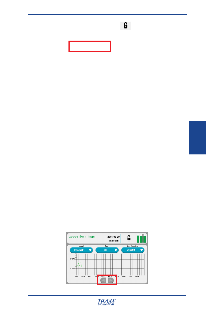
4.4 Levey Jennings Graphs
To generate a Levey Jennings graph on the analyzer,
proceed as follows:
1. Press the QC button on the Home screen.
The Quality Control Screen displays.
3. Press the Levey Jennings button to display the
Levey Jennings Graph screen.
4-4
Page 46
4 Reviewing Patient and QC Data
Figure 4.7 Quality Control Screen
4. Select the QC Level with the Level button for the
QC data. This displays a list of the levels that
have QC data.
5. Select the Test with the Test button. This
displays a list of the tests congured for the
analyzer.
6. Select the Lot Number with the Lot Number
button. This displays a list of the available lots
for the QC Level.
7. A graph dispays showing a Y-axis for the test
result and an X-axis for each day of a selected
level,lot, test, and month.
8. Touch the Right Arrow button to graph the QC
data of the next month that is available. Touch
the Left Arrow button to graph the QC data of
the prior month that is available.
9. To print the Levey Jennings Graph, press the
print icon on the footer of the screen.
4. Data
Figure 4.8 Levey Jennings Graph
4-5
Page 47
5 Consumables Replacement
5 Consumables Replacement
The following sections provide directions to operate and
maintain the Stat Prole Prime CCS Analyzer at peak
efciency. From the Home screen, press the Tool box icon
to display the System Menu screens (Figure 5.1). From
these screens, press the appropriate button to replace the
following consumables:
• MicroSensor Card
• Calibrator Cartridge
• Auto QC Cartridge
WARNING: Blood samples and blood products are
potential sources of infectious agents. Handle
all blood products, ow path components, and
accessories (waste-line, probe, MicroSensor
Card, clot catchers, ush tools/xtures, safety
sample port, etc.) with care. Gloves and
protective clothing are recommended. When
performing replacement and troubleshooting
procedures, also use protective eyewear.
5. Con Repl
Figure 5.1 System Menu Screens
The Cartridge Required screen (Figure 5.2) displays
when a new MicroSensor Card, Calibrator Cartridge, Auto
QC Cartridge, or Reference Cartridge has been removed
or requires replacement.
• The Sensor Card button displays if the
MicroSensor Card is not present, has zero
remaining life, or has not completed hydration.
5-1
Page 48

Prime CCS Instructions for Use Manual
Figure 5.2 Cartridge Required Screen
• The Calibrator Cartridge and/or Auto QC
Cartridge buttons display if the cartridge is not
present or has zero remaining life.
• The Reference Sensor button displays if the
Reference Sensor is not present.
Touching the button will bring you to the screen for
replacing this item.
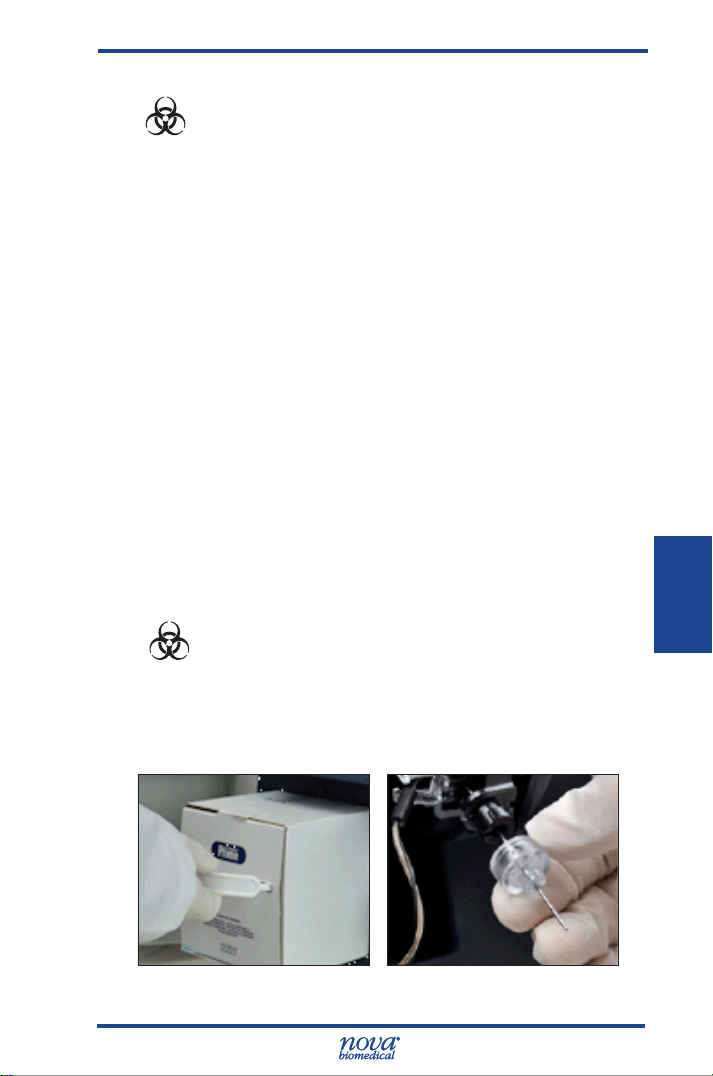
5.1 Calibrator Cartridge and Auto QC Cartridge Replacement
The Calibrator Cartridge and/or Auto QC Cartridge should
be changed when the system indicates the cartridge
is empty. From the Home screen, press the Tool Box
icon . Then press Replace Calibrator Cartridge or
Replace Auto QC, as needed.
Mix the cartridge thoroughly by gentle inversions.
Then follow the directions on the screen to replace the
cartridge and the Capillary Adaptor.
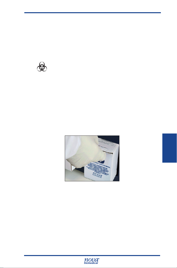
WARNING: When the Calibrator Cartridge or Auto QC
Cartridge is removed, keep your ngers and
hands away from the back of the cartridge
compartment. Sharp needles can cause
injury, and the waste needle is a biohazard.
5-2
Page 49
5 Consumables Replacement
WARNING: Exposure to Blood Borne Pathogens.
Follow laboratory procedures.
NOTE: The Calibrator Cartridge and the Auto QC
Cartridge must be replaced through the Tool
Box screens. If you remove and replace a
cartridge (even if it is the same one) outside of
these screens, you will not be able to prime the
analyzer, and you will not be able to calibrate or
to analyze samples (Calibrator Cartridge) or to
analyze internal controls (Auto QC Cartridge).
If you have removed and replaced a cartridge
outside of these screens, go to the appropriate
screen and press Prime.
NOTE: The Capillary Adaptor comes in the Calibrator
Cartridge box. It is very important for the proper
operation of the analyzer that the Capillary
Adaptor be changed with every Calibrator
Cartridge change.
5.1.1 Replace the Calibrator Cartridge
WARNING: Exposure to Blood Borne Pathogens.
Follow laboratory procedures.
5. Con Repl
1. Press the Tool Box icon.
2. From the System Menu, press the Replace
Calibrator Cartridge button.
Figure 5.3 Remove Calibrator Cartridge and Capillary Adaptor
5-3
Page 50

Prime CCS Instructions for Use Manual
3. Open the door and remove the cartridge.
4. Slide in a new cartridge past the front
retaining lip.
CAUTION: Probe will move when Enter is pressed.
5. To replace the Capillary Adaptor, press the Enter
button. Slide off the used capillary adaptor.
Slide on the adaptor provided with Calibrator
Cartridge.
6. Close the analyzer door. Press the Prime button.
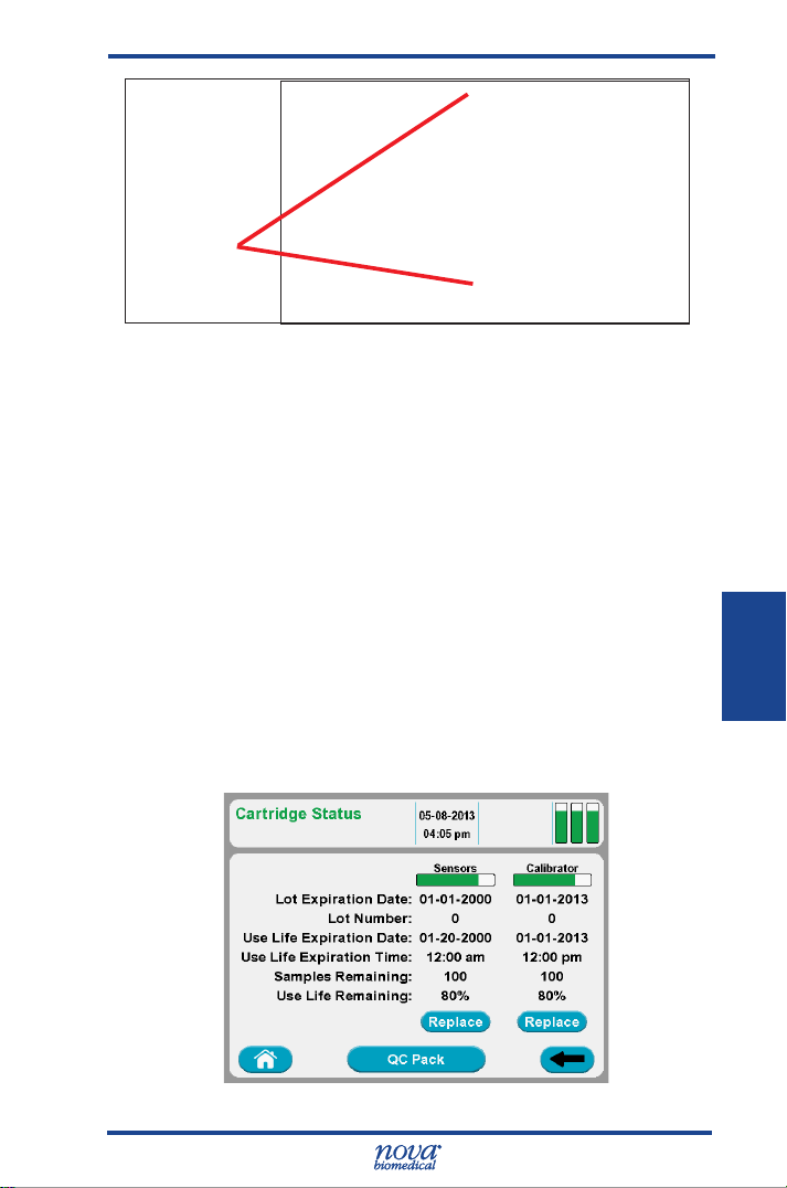
Calibrator Cartridge status can be viewed at any time by
pressing the Cartridge Status indicator icon at upper
right of the header bar.
5-4
Figure 5.4 MicroSensor Card Status
• The Calibrator status bar is empty (white) when
no Calibrator Cartridge is installed.
• The status bar is green and indicates the with
the remaining use life of the Calibrator Cartridge
when the use life remaining percentage is > 5%.
• The Calibrator status bar is orange when the
remaining use life is ≤ 5%.
• The screen displays the lot expiration date,
lot number, use life expiration date and time,
number of samples remaining, and percentage
use life remaining.
Page 51
5 Consumables Replacement
• When no cartridge is installed, all of the above
are blank.
• Press as appropriate the Install button or Replace
button.
5.1.2 Replace the Auto QC Cartridge
WARNING: Exposure to Blood Borne Pathogens.
Follow laboratory procedures.
1. Press the Tool Box icon.
2. From the System Menu, press the Replace
Auto QC button.
3. Open the analyzer door. Remove the Auto
QC Cartridge, if present.
4 Slide in a new cartridge, past the front
retaining lip.
5. Close the door. Press the Prime button.
5. Con Repl
Figure 5.5 Remove Auto QC Cartridge
Auto QC Cartridge status can be viewed at any time by
pressing the Status icon at upper right of the screen.
• The Auto QC status bar is empty (white) when
the Auto QC Cartridge is not installed.
• The Auto QC status bar is green when the
percentage remaining use life is > 5%.
5-5
Page 52

Prime CCS Instructions for Use Manual
Figure 5.6 Auto QC Cartridge Status
• The Auto QC bar is orange with the percentage
remaining use life of the Auto QC Cartridge if the
use life remaining percentage is ≤ 5%.
• The screen displays the lot expiration date,
lot number, use life expiration date, use life
expiration time, number of samples remaining,
and percentage use life remaining.
• If no pack is installed, all above is blank.
• There is either an install button to Install an Auto
QC Cartridge or a Replace button to replace an
Auto QC Cartridge.
5.2 Replace the MicroSensor Card
WARNING: Exposure to Blood Borne Pathogens.
Follow laboratory procedures.
1. Press the Tool Box icon.
2. From the System Menu, press the Replace
Sensor Card button. Wait for the pump to stop.
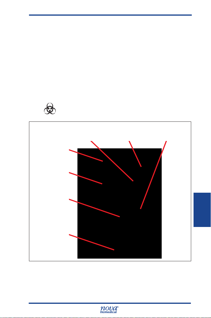
3. Open the analyzer door. Then open the
MicroSensor Card door. Remove the card.
NOTE: Hold the MicroSensor Card as indicated in
Figure 5.7.
5-6
Page 53
5 Consumables Replacement
Hold by
Edges
Figure 5.7 MicroSensor Card
4 Insert the new card. Close the MicroSensor Card
door.
5. Close the analyzer door. Press the Prime button.
MicroSensor Card status can be viewed at any time by
pressing the Status icon on the upper right corner of
the screen.
• The sensor status bar is empty (white) when no
MicroSensor Card is installed.
• The bar is green and indicates the remaining use
life of the MicroSensor Card if the remaining use
life is greater than 5%.
• The status
remaining use life
use life
bar is orange
and indicates the
of the MicroSensor Card if the
remaining is less than or equal to 5%.
5. Con Repl
Figure 5.8 MicroSensor Card Status
5-7
Page 54

Prime CCS Instructions for Use Manual
• The screen displays the lot expiration date,
the lot number, the use life expiration date, the
use life expiration time, the number of samples
remaining, the percentage use life remaining.
• If no MicroSensor Card is installed, all above is
blank.
• There is either an Install button to install a
MicroSensor Card or a Replace button to replace
the Card.
5.3 Prime MicroSensor Card Warranty Process
If one or more analytes are unable to calibrate within the
MicroSensor Card warrantied use life, the analyzer will
generate a 16-digit warranty code that can be submitted
for credit towards a new MicroSensor card.
The scenarios described in Table 5-1 generate a warranty
code.
Warranty code generation depends upon the answers
to a series of questions the user is prompted to answer.
Following is a description of the screens and choices
presented to the user.
1. If a MicroSensor Card fails prior to its stated
warranty, the user is presented with the
following screen.
5-8
Figure 5.9 Warranty Screen
2. The user must select one of three options:
• Option 1: “Claim Sensor Card”. This option
provides the user with a warranty code which will
reimburse them for all of the available parameters
remaining on the MicroSensor Card to the end of
Page 55

5 Consumables Replacement
Table 5-1 Failures that Generate Warranty Codes
Failure Mode Action
Hydration Failure –
PCO
channel
2
Hydration Failure –
All other parameters
PCO
channel failure
2
during normal use
Any other channel
in normal use
the warranty period. If this option is selected, the
software will permanently deactivate the card.
• Option 2: “Claim Sensor”. This option
provides the user with a credit for only the failed
parameter but does not disable the remaining
parameters. The user is allowed to continue
using the remaining parameters on the card for
patient testing.
• Option 3: Choose to defer the choice
by selecting the cancel button . This only
defers the choice until the next time the failure is
detected.
The entire card is disabled. A single warranty
code is generated. The customer must install a
new card.
The sensor is automatically disabled and
a warranty code is generated and printed
automatically. The customer can continue using
the card or disable the remaining channels. To
disable the remaining channels and generate
a code for the rest of the card, the user must
select the disabled sensor – and follow the
prompts.
The PCO
a warranty code is generated and printed
automatically. The customer can continue using
the card or disable the remaining channels. To
disable the remaining channels and generate
a code for the rest of the card, the user must
select the white PCO
prompts.
The customer is presented with a popup that
allows disabling of the sensor or card.
is automatically disabled and
2
icon and follow the
2
5. Con Repl
5-9
Page 56

Prime CCS Instructions for Use Manual
3. Once the user has made a selection, the
appropriate conrmation dialogues are
presented.
Figure 5.10 Conrmation Dialogs
4. After conrmation, the Stat Prole Prime
analyzer will automatically print and save the
16-digit code. The code is stored in the analyzer
for future retrieval and is not lost.
5. The warranty codes can be retrieved at a later
time by pressing Menu > Service > Credits. The
codes are searchable by date range or printed
status. Note that the “Printed” status (right hand
column) refers to a reprint initiated from this
screen. It does not refer to the automatic printing
that occurs. This allows for easy identication of
any unclaimed codes.
6. Once the code is generated, the user must
provide it to customer support for a warranty
credit. Customers in the USA should contact
Nova Technical Support at 800-545–6682, In
Canada contact Nova Technical Support at
1-800-263-5999. Outside the USA or Canada
contact your local distributor.
5-10
Figure 5.11 Warranty Credits Screen
Page 57
6 Periodic Replacements
6 Periodic Replacements
Periodically the Pump Tubing Harness, Reference
Cartridge
replaced. This section gives procedures on replacements of
these consumable Items.
6.1 Pump Tubing Harness Replacement
The Pump Tubing Harness should be replaced at
intervals prescribed in the maintenance log. Replace the
tubing that goes around the pump as follows.
WARNING: Exposure to Blood Borne Pathogens.
, Sample Probe, or printer paper may need to be
Follow laboratory procedures.
Waste (W)
Line
Pressure
Plate
Tab of Tubing
Clip
Pump Tubing
Manifold; to
Reference
Cartridge
Pressure Plate
Release Button
Figure 6.1 Pump Tubing
Reference (R)
Line
Tubing Clip
6. Periodic
6-1
Page 58

Prime CCS Instructions for Use Manual
Figure 6.2 Replace and Install Pump Tubing Screens
1. From the Home screen, press the Tool Box icon.
2. From the System Menu, select Replace Pump
Tubing. Wait for the pump to stop.
3. Open the analyzer door. Then open the
MicroSensor Card door. Remove the
MicroSensor Card, if present.
4. Push the white button to release the Pump
Tubing Pressure Plate.
6-2
Figure 6.3 Release Pump Tubing Pressure Plate
5. Disconnect the W
and R tubes from the
analyzer.
6. Disconnect the tubing
connector from the
Reference Cartridge.
7. Remove the tubing
harness and discard.
8. Press the Enter
button to continue.
Figure 6.4
Disconnect Pump Manifold
Page 59

6 Periodic Replacements
Figure 6.5 Disonnect Tubing Connector from Reference Cartridge
6.1.1 Install the Pump Tubing
1. Install the tubing over the pump rollers.
2. Slide the tubing bracket under the locating tabs.
3. Connect the tubing connector to the Reference
Cartridge.
4. Connect the W and R tubes to the analyzer.
5. Close and latch the Pump Tubing Pressure
Plate.
6. Insert the MicroSensor Card.
7. Close the MicroSensor Card door.
8. Close the analyzer door.
9. Press the Prime button to continue.
6. Periodic
6-3
Page 60

Prime CCS Instructions for Use Manual
6.2 Probe Replacement
WARNING: Exposure to Blood Borne Pathogens.
Follow laboratory procedures.
If the Probe or Sample/Air Detector line become
damaged, replace the assembly. Use the following
procedure:
1.
From the Home screen, press the Tool Box
icon. From the System Menu select Replace S-Line
Probe and wait for the pump to stop.
2. Remove the capillary adaptor from the front of the
probe by gently pulling (Figure 6.6).
3. Disconnect the Air Detector Tube (Figure 6.7).
4. Disconnect the Air Detector Sample Line from the
Reference Cartridge module using the removal
Air Detector Tube
Connector
Figure 6.6
Remove Capillary Adaptor
6-4
Figure 6.7 Disconnect
Air Detector Tube
Page 61
6 Periodic Replacements
Removal Tool
Sample (S)-Line (connects to
Reference Cartridge)
Figure 6.8 Remove the S-line from the Reference Cartridge
tool (Figure 6.8).
5. Squeeze the white pinch clamp (Figure 6.9).
Remove the Probe, S-line, and Air Detector tube
Pinch
Clamp
S-Line (clear)
with Connection
to Reference
Cartridge
Air Detector
Line (gray) to
Analyzer
Figure 6.9 Remove Probe, S-line, and Air Detector Line
and discard.
6. Insert the new Probe assembly until it clicks into
place.
7. Install the Capillary Adaptor onto the probe.
8. Reconnect the S-line to the Reference Cartridge
9. Reconnect the Air Detector line into the analyzer.
10. Close the door.
11. Press the Calibrate button.
6-5
6. Periodic
Page 62

Prime CCS Instructions for Use Manual
6.3 Reference Cartridge Replacement
WARNING: Exposure to Blood Borne Pathogens.
Follow laboratory procedures.
1. From the Home screen, press the Tool Box icon.
2. From the System Menu, select the Replace Reference
button.
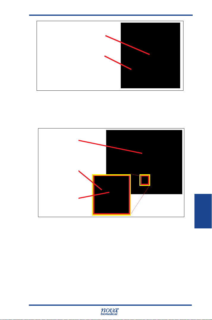
3. Open the door. Open the MicroSensor Card door.
4 Remove the MicroSensor Card, if present.
5. Disconnect the Sample (S)-line from the bottom of the
Reference Cartridge (Figure 6.10).
Pump Tubing
Manifold
Reference
Cartridge
MicroSensor
Card
6-6
S-Line
Figure 6.10 Reference Cartridge
6. Disconnect the Pump Tubing from the top of the
Reference Cartridge.
7. Slide the Reference Cartridge right to remove (Figure
6.11)..
8. Press the Enter button to continue.
Page 63

6 Periodic Replacements
Figure 6.11 Slide the Reference Cartridge Right to Remove
6.3.1 Install the Reference Cartridge
1. Position the new Reference Cartridge to the right of its
installed position.
2. Slide the Reference Cartridge left and into place.
3. Attach the S-Line to the bottom and Pump Tubing to
the top.
4. Insert the MicroSensor Card.
5. Close the MicroSensor Card door.
6. Close the analyzer door.
7. Press the Prime button to continue.
6. Periodic
6-7
Page 64

Prime CCS Instructions for Use Manual
6.4 Printer Paper Replacement
1. Open the printer cover.
2. Remove the depleted roll of paper.
3. Insert a new roll of paper. The loose end of the paper
should feed from the bottom of the roll.
4. Feed paper past the cover. Then close the printer
cover.
6-8
Figure 6.12 Replace the Printer Paper
Page 65

6 Periodic Replacements
6.5 Safety Sample Port Replacement
WARNING: Exposure to Blood Borne Pathogens.
Follow laboratory procedures.
1. Open the door.
2. Slide out the old Safety Sample Port.
3. Slide in a new Safety Sample Port.
4. Close the door.
Squeeze Pinch
Clamp to Remove
Safety Sample
Port
Figure 6.13 Replace the Safety Sample Port
6-9
6. Periodic
Page 66

Prime CCS Instructions for Use Manual
6-10
Page 67

7 Troubleshooting
7 Troubleshooting
This section describes the recommended troubleshooting
procedures for use with the Stat Prole Prime CCS
analyzer. The procedures use the most logical and
direct steps to resolve each problem and are written to
minimize the replacement of any unnecessary parts. If
the recommended solutions do not resolve the problem
please contact Nova Biomedical Technical Support for
troubleshooting assistance.
FOR TECHNICAL ASSISTANCE, CALL TOLL FREE:
USA 1-800-545-NOVA
Canada 1-800-263-5999
Other Countries Contact the local Nova
Biomedical Sales Ofce or
Authorized Nova Biomedical
Distributor
WARNING: Blood samples and blood products
are potential sources of infectious agents.
Handle all blood products, accessories,
and ow path components (waste-line,
capillary adaptor, probe, sensor cartridge,
etc.) with care. Gloves and protective
clothing are recommended. When
performing maintenance and troubleshooting
procedures, also use protective eyewear.
7. Trshoot.
7-1
Page 68

Prime CCS Instructions for Use Manual
7.1 Event Log
The Event Log displays a list of events that have
occurred during a selected time frame. To access the
Event Log: from the Home Screen, press:
> > >
The Event Log initially displays events that occurred on
the current date but may be changed to show events that
occurred during a specied time frame or that contain a
specic Event ID. Events are displayed chronologically,
with the most recent event at the top of the page.
Each event is shown with the date and time the event
occurred, the event ID and a description of the event.
To view additional details of a specic event, select
(highlight) the event of interest then press the Details
button . To print the Event Log press .
Figure 7.1 Event Screen
7.2 Resolving Event Codes
Event Codes are grouped into one of 5 categories,
Cartridge errors, Flow errors, Printer errors, MicroSensor
Card errors, and Hardware/Software errors. Use the
following troubleshooting steps to resolve the listed
codes.
If a displayed code is not listed, please contact Nova
Biomedical Technical Support for assistance.
7-2
Page 69

7 Troubleshooting
7.2.1 Flow Event Codes
Event
Code
Description and Corrective Action
602 Insufcient Sample – During the last sample
analysis, the leading edge of the sample was
not detected at the reference air detector when
expected.
Recommended Solution
1. Rerun the sample and insure the sample probe
is not being obstructed by the sample container.
2. Flush the ow path with deionized water and
recalibrate the analyzer. Refer to Section 7.3,
Flushing the Flow Path.
3. Replace the W/R Pump Harness.
4. Contact Nova Biomedical Technical Support.
604 No Flush When Required – During the last
calibration or sample analysis, Flush solution
was not detected when expected.
Recommended Solution
1. Verify the % remaining in the Calibrator
Cartridge. If the pack indicates less than 10%
remaining, replace the Calibrator Cartridge.
2. Flush the ow path with deionized water and
recalibrate the analyzer. Refer to Section 7.3,
Flushing the Flow Path.
3. Calibrate the Air Detector.
4. Contact Nova Biomedical Technical Support.
7. Trshoot.
7-3
Page 70

Prime CCS Instructions for Use Manual
605 No Air When Required - During the last
calibration or sample analysis, Air was not
detected when expected.
Recommended Solution
1. Flush the ow path with deionized water and
recalibrate the analyzer. Refer to Section 7.3,
Flushing the Prime Flow Path.
2. Calibrate the Air Detector.
3. Contact Nova Biomedical Technical Support.
606 No Standard A When Required - During the
last calibration or sample analysis, calibrator
standard A solution was not detected when
expected.
Recommended Solution
1. Verify the % remaining in the Calibrator
Cartridge. If the pack indicates less than 10%
remaining, replace the Calibrator Cartridge.
2. Flush the ow path with deionized water and
recalibrate the analyzer. Refer to Section 7.3,
Flushing the Flow Path.
3. Calibrate the Air Detector.
4. Contact Nova Biomedical Technical Support.
607 No Standard B When Required - During the
last calibration, calibrator standard B solution
was not detected when expected.
Recommended Solution
1. Verify the % remaining in the Calibrator
Cartridge. If the pack indicates less than 10%
remaining, replace the Calibrator Cartridge.
2. Flush the ow path with deionized water and
recalibrate the analyzer. Refer to Section 7.3,
Flushing the Flow Path.
3. Calibrate the Air Detector.
4. Contact Nova Biomedical Technical Support.
7-4
Page 71

7 Troubleshooting
608 No Internal QC When Required – During the
last Internal QC analysis, QC solution was not
detected when expected.
Recommended Solution
1. Verify the % remaining in the Internal QC
Cartridge. If the pack indicates less than 10%
remaining, replace the QC Cartridge.
2. Flush the ow path with deionized water and
recalibrate the analyzer. Refer to Section 7.3,
Flushing the Flow Path.
3. Calibrate the Air Detector.
4. Contact Nova Biomedical Technical Support.
609 No Sample When Required – During the last
sample analysis, no sample was detected by
the analyzer.
Recommended Solutions
1. If analyzing a whole blood sample, verify that
the sample is not clotted. If the sample is clotted,
Nova Biomedical recommends that the sample
be redrawn or that a clot catcher be utilized prior
to repeating the analysis.
2. If analyzing an external QC sample, repeat the
analysis. If the problem recurs, proceed to step
3.
3. Flush the ow path with deionized water and
recalibrate the analyzer. Refer to Section 7.3,
Flushing the Flow Path.
4. Calibrate the Air Detector.
5. Contact Nova Biomedical Technical Support.
7. Trshoot.
7-5
Page 72

Prime CCS Instructions for Use Manual
611 Sample Position Not Conrmed – During the
last analysis, the sample was not detected at
one of the air detectors.
Recommended Solutions
1. If analyzing a whole blood sample, verify that
the sample is not clotted. If the sample is clotted,
Nova Biomedical recommends that the sample
be redrawn or that a clot catcher be utilized prior
to repeating the analysis.
2. If analyzing an external QC sample, repeat the
analysis. If the problem recurs, proceed to step
3.
3. Flush the ow path with deionized water and
recalibrate the analyzer. Refer to Section 7.3,
Flushing the Flow Path.
4. Contact Nova Biomedical Technical Support.
7-6
Page 73

7 Troubleshooting
7.2.2 Printer Event Codes
Event
Code
Description and Corrective Action
904 Printer Paper Out – No paper was detected in
the thermal printer.
Recommended Solution
1. Check and or replace printer paper supply.
2. Contact Nova Biomedical Technical Support if
printer paper is not recognized.
905 Printer Cover Open – The printer cover is not
completely closed.
Recommended Solution
1. Insure the printer cover is fully closed.
2. Contact Nova Biomedical Technical Support if
unable to resolve.
906 Printer – A printer error has occurred.
Recommended Solution
1. Check the printer paper supply. Clear any paper
jam that may have occurred.
2. Contact Nova Biomedical Technical Support if
unable to resolve.
7. Trshoot.
7-7
Page 74

Prime CCS Instructions for Use Manual
7.2.3 MicroSensor Card Event Codes
Event
Code
1201
1209
1217
1225
1233
1241
1249
1257
1265
1289
1297
Description and Corrective Action
Slope
pH Slope
PO2 Slope
PCO2 Slope
K Slope
Na Slope
The measured difference
between the indicated
analytes’ calibration
standards did not meet the
minimum specications
for a properly performing
sensor during the last
2-point calibration.
Cl Slope
Ca Slope
Hct Slope
Glucose Slope
Lactate Slope
Recommended Solution
1. Recalibrate the analyzer.
2. Flush the ow path and recalibrate the analyzer.
Refer to Section 7.3.2, Flushing the Flow Path.
3. Replace the MicroSensor Card.
4. Replace the Calibrator Cartridge.
5. Replace the Reference Cartridge.
6. Call Nova Biomedical Technical Support.
7-8
Page 75

7 Troubleshooting
1202
1210
1218
1226
1234
1242
1250
1258
1266
1290
1298
Overload
pH Overload
PO2 Overload
PCO2 Overload
During the last calibration
or analysis sequence, the
indicated analytes’ sensor
reading exceeded the
software limits.
K Overload
Na Overload
Cl Overload
Ca Overload
Hct Overload
Glu Overload
Lac Overload
Recommended Solution
1. Recalibrate the analyzer.
2. Flush the ow path and recalibrate the analyzer.
Refer to Section 7.3.2 Flushing the Flow Path.
3. Replace the MicroSensor Card.
4. Call Nova Biomedical Technical Support.
7-9
7. Trshoot.
Page 76

Prime CCS Instructions for Use Manual
1205
1213
1221
1229
1237
1245
1253
1261
1269
1293
1301
Stability
pH Stability
PO2 Stability
PCO2 Stability
During the last calibration
or analysis sequence, the
indicated analytes’ sensor
did not reach a stable
endpoint.
K Stability
Na Stability
Cl Stability
Ca Stability
Hct Stability
Glu Stability
Lac Stability
Recommended Solution
1. Recalibrate the analyzer.
2. Flush the ow path and recalibrate the analyzer.
Refer to Section 7.3.2 Flushing the Flow Path.
3. Replace the MicroSensor Card.
4. Replace the Reference Cartridge.
5. Call Nova Biomedical Technical Support.
7-10
Page 77

7 Troubleshooting
1206
1214
1222
1230
1238
1246
1254
1262
1270
1294
1302
E-Zero Drift
pH E-Zero Drift
PO2 E-Zero Drift
P
CO2 E-Zero Drift
K E-Zero Drift
During the last analysis
sequence, the indicated
analytes’ performance
changed signicantly since
the last successful 2-point
calibration.
Na E-Zero Drift
Cl E-Zero Drift
Ca E-Zero Drift
Hct E-Zero Drift
Glu E-Zero Drift
Lac E-Zero Drift
Recommended Solution
1. Recalibrate the analyzer.
2. If the problem persists, ush the ow path and
recalibrate the analyzer. Refer to Section 7.3.2,
Flushing the Flow Path.
3. Replace the MicroSensor Card.
4. Call Nova Biomedical Technical Support.
7-11
7. Trshoot.
Page 78

Prime CCS Instructions for Use Manual
1207
1215
1223
1231
1239
1247
1255
1263
1271
1295
1303
A to A Drift
pH A to A Drift
During the last analysis
sequence, the indicated
analytes’ performance
PO2 A to A Drift
PCO2 A to A
changed signicantly from
the previous analysis.
Drift
K A to A Drift
Na A to A Drift
Cl A to A Drift
Ca A to A Drift
Hct A to A Drift
Glu A to A Drift
Lac A to A Drift
Recommended Solution
1. Recalibrate the analyzer.
2. If the problem persists, ush the ow path and
recalibrate the analyzer. Refer to Section 7.3.2
Flushing the Flow Path.
3. Replace the MicroSensor Card.
4. Call Nova Biomedical Technical Support.
7-12
Page 79

7 Troubleshooting
1208
1216
1224
1232
1240
1248
1256
1264
1272
1296
1304
Slope Drift
pH Slope Drift
PO2 Slope Drift
P
CO2 Slope
Drift
K Slope Drift
Na Slope Drift
Cl Slope Drift
Ca Slope Drift
Hct Slope Drift
Glu Slope Drift
Lac Slope Drift
Recommended Solution
1. Recalibrate the analyzer.
2. If the problem persists, ush the ow path
and recalibrate the analyzer.
3. Replace the MicroSensor Card.
4. Call Nova Biomedical Technical Support.
During the last calibration,
the indicated analytes’
performance changed
signicantly from the
previous calibration.
7-13
7. Trshoot.
Page 80

Prime CCS Instructions for Use Manual
7.3 Troubleshooting Flow Problems
The analyzer may experience ow problems as a result
of aspirating clots from poorly heparinized whole blood
samples. If this should occur operators can use the
following procedures to clear the analyzer ow path
and verify the analyzer is capable of aspirating from the
sample probe.
NOTE: Nova Biomedical recommends but does not
require the use of clot catchers as an effective
means of preventing the aspiration of clots into
the analyzer’s ow path.
7.3.1 The Flow Path Flush Tool
The Flow Path Flush Tool (Figure 7.2) consists of a 30
mL syringe and a special adaptor to safely clear the ow
path in the event it becomes obstructed.
The tool can be used with or without the adaptor to ush
individual ow path components. The adaptor is keyed to
connect to the Reference Cartridge in only one direction
(Figure 7.3). The tubing connected to the adaptor
should point up to ensure it is not pinched shut when the
MicroSensor Card door is closed.
7-14
Figure 7.2 Flow Path Flush Tool
Page 81

7 Troubleshooting
Figure 7.3 Tubing Connected to the Adaptor Points Up
7.3.2 Flushing the Flow Path
The analyzer’s ow path can be ushed to remove clots
or other debris that may have been aspirated into the
system. Use of a device other than the Flush Tool may
damage the MicroSensor Card and is not recommended.
Following is the recommended procedure for clearing the
ow path when needed.
1. From the Home screen, press >
2. When the pump stops turning, open the analyzer
door then open the MicroSensor Card door.
3. Aspirate a small amount of deionized water into
the Flow Path Flush Tool.
4. Disconnect the W/R Pump Harness from the
Reference Cartridge.
Figure 7.4 Flush Flow Path Screens
7-15
7. Trshoot.
Page 82

Prime CCS Instructions for Use Manual
5. Connect the Flush Tool to the Reference
Cartridge and close the MicroSensor Card door.
6. Using moderate pressure, carefully ush the
ow path with 1-2 ml of deionized water into a
container placed in front of the sample probe.
7. Rell the Flush Tool with air and ush the ow
path to remove any remaining liquid.
8. Disconnect the Flushing Tool and reattach the
W/R tubing harness to the Reference Cartridge.
9. Close the MicroSensor Card door; press Done.
10. Recalibrate the analyzer 3 times.
7-16
Figure 7.5
Flushing the Flow Path into Gauze
Page 83

7 Troubleshooting
7.3.3 Flushing the Sample Probe/S-Line
The Sample Probe is designed to prevent large clots and
other debris from advancing into the analyzer’s ow path
if possible. As a result, the sample probe may become
obstructed and require manual ushing to remove an
obstruction. Following is the recommended procedure for
clearing obstructions from the sample probe and S-line.
1. From the Home screen, press >
2. When the pump stops turning, open the
analyzer door.
3. Draw a small amount of deionized water into the
Flow Path Flush Tool.
4. Carefully disconnect the Sample probe/Sline tubing from the bottom of the Reference
Cartridge using the removal tool.
5. Slide the ush tool tubing over the extended
sample probe.
6. Using moderate pressure, ush water through
the sample probe and S-line into a container or
gauze placed in front of the S-line.
7. Rell the Flush Tool with air and ush the
sample probe to remove any remaining liquid.
8. Press Done when nished.
9. Recalibrate the analyzer as needed.
Figure 7.6 Flushing the S-Line
7-17
7. Trshoot.
Page 84

Prime CCS Instructions for Use Manual
7.3.4 Flow Test
The following procedure can be used to verify the
analyzer is able to aspirate from the sample probe. Use
this procedure in tandem with the ushing procedures to
clear obstructions and verify ow.
1. From the Home Screen, press
2. Once the pump stops and the sample probe has
been extended, press to scroll to page 2.
3. Fill a small container with de-ionized water and
immerse the sample probe into the water.
4. Press on the display to start the
peristaltic pump.
The water level in the container should drop quickly if the
analyzer is aspirating correctly.
5. Press Done when nished.
6. Recalibrate the analyzer as needed.
>
7-18
Figure 7.7 Flow Test
Page 85

7 Troubleshooting
7.4 Long Term Shutdown
The Prime ABG analyzer can be safely shut down for
several hours without taking any special precautions.
However, if the analyzer is to be shut down for a longer
period, the following shutdown procedure is strongly
recommended.
1. Remove the Calibrator Cartridge and Internal QC
Cartridge from the analyzer.
2. Insert the Calibrator Flush Fixture into the Calibrator
Cartridge bay. Insert the Control Flush Fixture into
the Internal QC Cartridge bay.
3. Place the Waste (W) line into an empty container.
Place the remaining tubing lines into a container of
deionized water.
4. From the Home screen, press Toolbox > Service >
Diagnostics.
5. Press the Pump Speed button. Select Very Fast.
6. Press the Rotary Valve and select Flush.
7. Press Run Pump. Allow the pump to run long enough
to ensure that water has passed through the entire
owpath and into the waste container.
8. Repeat Steps 6 and 7, selecting Standard A,
Standard B, and OBC (On Board Control) 1, 2 and 3.
9. Remove the tubing lines from the container of
deionized water. Repeat Steps 6, 7, and 8 until all
water has been ushed from the system.
10. Remove the Flush Fixtures. Remove the pump tubing
harness from the pump. Power off the analyzer.
7. Trshoot.
7-19
Page 86

Appendix A
A Appendix
Appendix A includes analyzer specications, performance
data, solutions and reagents, consumables lists,
reference information, and warranty terms for the Stat
Prole Prime CCS Analyzer.
A.1Specications
Analyte Measurement Ranges
Analyte
pH
PCO2
PO2 5.0 - 765.0 mmHg 0.66 - 102.00 kPa
Hct 12% - 70%
Na+ 80.0 - 200.0 mmol/L
K+ 1.0 - 20.0 mmol/L
Cl- 50.0 - 200.0 mmol/L
iCa 0.20 - 2.70 mmol/L 0.8 - 10.8 mg/dL
Glu 15 - 500 mg/dL 0.8 - 28.0 mmol/L
Lac 0.4 - 20.0 mmol/L 4 - 178 mg/dL
Default Alternate
6.500 - 8.000 (pH units) 316.2 - 10.0 nmol/L (H+ units)
3.0 - 200.0 mmHg 0.40 - 26.70 kPa
Units of Measure
Appendix A
A-1
Page 87
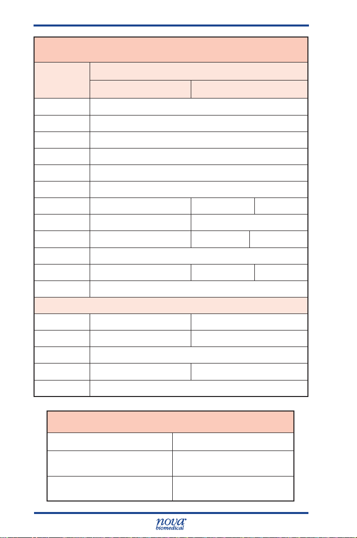
Prime CCS Instructions for Use Manual
Calculated Result Resolution
Parameter
Units of Measure
Default Alternate
-
HCO
TCO
3
2
0.1 mmol/L
0.1 mmol/L
nCa 0.1 mmol/L
BE-ecf 0.1 mmol/L
BE-B 0.1 mmol/L
SBC 0.1 mmol/L
O2Ct 0.1 mL/dL 1 mL/L 0.1 mmol/L
P50 0.1 mmHg 0.1 kPa
O2Cap 0.1 mL/dL 1 mL/L 0.1 mmol/L
SO2% 0.1
Hb 0.1 g/dL 0.1 mmol/L 1 g/L
Anion Gap 0.1 mmol/L
With Entered FiO
2
A 0.1 mmHg 0.01 kPa
AaDO
2
0.1 mmHg 0.01 kPa
a/A 0.1
PO2/FiO
2
0.1 mmHg 0.01 kPa
RI 0.1
Acceptable Sample
Sample Volume,
Capillary or Syringe
Barometer
A-2
Sample
Whole Blood (heparinized)
100 µL
400 – 800 ±1 mmHg,
accurate to 1.5%
Page 88

Appendix A
A.2 Quality Control and Calibration
A.2.1 Traceability of Calibrators, Controls, and Standards
Chemistry analytes are traceable to the Standard
Reference Materials of the National Institute of Standards
and Technology (NIST). SO
A.2.2 Quality Control
Healthcare facilities should follow federal, state, and
local guidelines for testing quality control materials.
At a minimum, Nova Biomedical recommends that
each laboratory performs the following minimum QC
procedures (Auto-Cartridge QC or External Ampule QC)
on each analyzer:
• During each 8 hours of testing, analyze one level
of Control.
• Analyze all 3 levels during each day of operation.
• After performing system maintenance, follow
good laboratory practice guidelines for
performing quality control analysis.
CAUTION: Sensor performance may be affected
by use of controls other than Stat Prole
Prime Controls. Contact Nova Biomedical for
additional information.
When a new lot number of Auto-Cartridge QC is installed,
the previous lot number becomes inactive. Thus, you are
unable to run lots in parallel to validate the new lot to the
old by alternating packs on the same unit.
Nova Recommendation: All Nova controls ship with a product
insert sheet. This product insert sheet contains the target
value ranges for each level of QC contained in the pack.
Nova’s recommendation for conversion to a new lot
number is to use the product insert sheet range levels
for the rst 30 days or until sufcient data is collected
to establish the new target values. After sufcient data
is collected, the established values and ranges can be
entered into the analyzer.
is traceable to tonometry.
2
Appendix A
A-3
Page 89

Prime CCS Instructions for Use Manual
Alternate Method: If this method is inadequate, Nova
recommends the use of the external controls run in
parallel and overlapping with the on-board product
change over. This method offers continuity in monitoring
performance during the change over period. The external
QC monitoring can be done using the QC program on the
analyzer.
A.2.3 Calibrator Cartridge
In addition to the calibrators and solutions, the Calibrator
Cartridge has a self-contained waste bag for safe
disposal of waste. For information on Automatic and
Manual Calibrations, see Section 2.4
A.3AnalyticalSpecicity,HumanWholeBlood
An interference study was performed according to CLSI
guideline EP7-A2. The study used spiked and diluted
human specimens containing potential interfering
substances for pH, PO2, PCO
and lactate at normal physiological levels. Each sample
containing the interfering substance was evaluated
against a reference specimen without the interfering
substance.
Potential interfering substances were selected for test
based upon a known potential to interfere with the test
methodology. The following table represents substances
that were tested without demonstrating a clinically
signicant effect on test results:
, Na, K, iCa, Cl, glucose
2
A-4
Page 90

Appendix A
Interfering
Substance
Highest
Concentration
Tested
Analytes Tested
Acetaminophen 20.0 mg/dL Glu, Lac
Acetoacetate 2.0 mmol/L
pH, Na, K, iCa, Cl, Glu,
Lac
Acetylsalicylic acid 3.62 mmol/L Na, K, Cl, Glu, Lac
Albumin 15 g/dL Hct
Ammonium Chloride 107.0 µmol/L Na, K, Cl, iCa, Glu, Lac
Ascorbic Acid 50 mg/dL Cl, Glu, Lac
Benzylkonium Chloride
BetaHydroxybutyrate
Bilirubin
10.0 mg/L
2.0 mmol.L Glu, Lac
20.0 mg/dL
Calcium Chloride 2.0 mmol/L pH,PCO
pH, Na, K, Cl, iCa, Glu,
Lac
Hct, pH, PCO
, PO2,
2
Na,K,Cl,iCa,Glu,Lac
,PO2,Na,K
2
D-Galactose 1.0 mmol/L Glu, Lac
Dobutamine 2.0 mg/dL pH,Na,K,iCa,Glu, Lac
Dopamine Hydrochloride
5.87 µmol/L Glu, Lac
EDTA 3.4 umol/L Glu, Lac
Ethanol 86.8 mmol/L Glu,Lac,pH,PCO
Fluorescein 1.0 mmol/L PCO2, PO
, PO
2
2
Fluoride 105 µmol/L Glu, Lac
Glucose 1,000 mg/dL Lac
Glycolic Acid 1 mmol/L Glu, Lac
Glucosamine 30.0 µmol/L Glu, Lac
Hemoglobin 2.0 g/L
Hct, pH, PCO
Na,K,Cl iCa, Glu, Lac
, PO2,
2
Heparin 100 IU/mL Glu, Lac, Hct
Ibuprofen 2.4 mmol/L Na, K, iCa, Cl, Glu, Lac
2
Appendix A
Continued on next page
A-5
Page 91

Prime CCS Instructions for Use Manual
Continued from previous page
Interfering
Substance
Intralipid 10.0 mg/mL
Lithium Lactate 6.6 mmol/L Na, K, iCa, Glu
Magnesium Chloride 15.0 mmol/L Na, Cl
Maltose 13.0 mmol/L Glu, Lac
Mannose 1.0 mmol/L Glu, Lac
Perchlorate 1.0 mmol/L iCa
Potassium Chloride 5.0 mmol/L pH, PCO
Pyruvate 309 µmol/L Glu, Lac
Salicylic Acid 4.34 mmol/L Na, K, Cl, Glu, Lac
Sodium Bromide 37.5 mmol/L pH, K, iCa, Lac
Sodium Chloride 10.0 mmol/L pH, PCO2, PO2, iCa
Sodium Citrate 12.0 mmol/L Cl, Glu, Lac
Sodium Oxalate 500 mg/dL Cl, Glu, Lac
Thiocyanate 6.8 mmol/L Cl, Glu, Lac
Urea 40.0 mg/dL Lac
Uric Acid 1.4 mmol/L Lac
Xylose 25.0 mg/dL Glu, Lac
Zinc Chloride 1.3 mg/dL Na, K, iCa
Highest
Concentration
Tested
Analytes Tested
Hct, pH, PCO
Na,K,Cl iCa, Glu, Lac
, PO2,
2
, PO2, iCa
2
A-6
Page 92
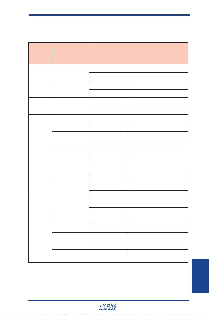
Appendix A
The following table represents substances that were
tested that demonstrated a clinically signicant effect on
test results.
Analyte
Chloride
Ionized
Calcium
Glucose
Lactate
Hct
Interfering
Substance
Bromide
Thiocyanate
MgCl
2
Hydroxyurea 0.2 mg/dL No interference observed
Oxalate
Thiocyanate
Glycolic acid 0.0 mmol/L No interference observed
Hydroxyurea 0.0 mg/dL No interference observed
Albumin
Hemolysis
Triglycerides
White Blood
Count (WBC)
Concentration Interference
2.5 mmol/L No interference observed
5.0 mmol/L Bias of 12.7%
3.4 mmol/L No interference observed
5.1 mmol/L Bias of 15.2%
3.75 mmol/L No interference observed
7.50 mmol/L Bias of 13.5%
0.4 mg/dL Bias of 19.2%
125 mg/dL No interference observed
250 mg/dL Bias of -10.9%
1.7 mmol/L No interference observed
3.4 mmol/L Bias of 10.0%
0.25 mmol/L Bias of 11.7%
0.2 mg/dL Bias of 20.1%
2.8 g/dL No interference observed
5.7 g/dL Bias of 12.7%
5% No interference observed
10% Bias of -10.7%
986.4 mg/dL No interference observed
1233 mg/dL Bias of 12.9%
>50,000 WBC/µL May increase the Hct Value
Appendix A
NOTE: Elevated White Blood Count (WBC) >50,000
WBC/μL may increase the Hct Value.
A-7
18
Page 93

Prime CCS Instructions for Use Manual
A.4 Healthcare Professional Analytical Performance
Studies
Three Stat Prole Prime CCS analyzers were
compared to 2 Stat Prole pHOx Ultra Analyzers in
a laboratory setting by healthcare professionals. The
protocol consisted of within run precision runs, dayto-day precision runs, linearity validation, and method
comparison studies comparing the performance of the
Stat Prole Prime CCS Analyzers to the Stat Prole
pHOx Ultra Analyzers.
A.4.1 Method Comparison Study
Lithium Heparin arterial whole blood discarded
specimens from hospital patients were analyzed in
duplicate on the 3 Stat Prole Prime CCS Analyzers
and 2 Stat Prole pHOx Ultra reference analyzers. The
number of samples per run and the total number of
runs each day depended upon the availability of blood
specimens on any given test day. Some additional
whole blood specimens from consenting donors were
tonometered, spiked, or diluted with saline to cover
the analytical measurement range for all analytes. The
number of data points (N) varies for each parameter
due to error, instrument calibration status, or insufcient
sample volume.
A minimum of 150 whole blood specimens were analyzed
for each parameter in syringe collection devices. The
samples were analyzed on each of the Stat Prole Prime
CCS analyzers and on each of the pHOx Ultra analyzers.
The Stat Prole Prime CCS results for each analyzer
were compared to the average of the 2 results from the
pHOx Ultra comparative method.
A minimum of 100 whole blood specimens were analyzed
for each parameter in capillary collection tubes. Each
specimen was analyzed one time from a capillary
container on each Stat Prole Prime CCS analyzer and
then immediately run as a syringe specimen on the
same Stat Prole Prime CCS analyzer. The capillary test
result was compared to the syringe result from each test
system.
A-8
Page 94

Appendix A
Bias Chart Results
The method comparison bias estimate was analyzed
using CLSI Standard EP09-A2 as a reference document.
The bias plots for each parameter are summarized and
include boundary lines that represent the 95% condence
interval across the measurement range based upon
each parameter’s between analyzer day-to-day (+/-2SD)
performance specication or CV% (whichever is greater).
Each bias plot represents 3 Stat Prole Prime CCS
analyzers compared to the average result from 2 Stat
Prole pHOx Ultra analyzers. Medically relevant low and
high concentrations are annotated.
A-9
Appendix A
Page 95

Prime CCS Instructions for Use Manual
A-10
Page 96

Appendix A
A-11
Appendix A
Page 97

Prime CCS Instructions for Use Manual
A-12
Page 98

Appendix A
iCa Bias Plot
A-13
Appendix A
Page 99

Prime CCS Instructions for Use Manual
Syringe Method Comparison Study Results
vs. Stat Prole pHOx Ultra
Test
Parameter
pH
PCO
2
PO
2
Hct
Na
K
iCa
Cl
Glu
Lac
Analyzer
#1 172 40
#2 170 38
#3 168 41
#1 179 34 3.4 - 200.0 0.9854 0.9344 0.9977
#2 181 29 3.1 - 192.6 1.0091 0.1547 0.9920
#3 176 32 3.3 - 199.10 1.0019 1.1679 0.9980
#1 177 43 26.9 - 586.3 1.0046 -1.2710 0.9986
#2 167 43 29.5 - 593.2 0.9897 1.4508 0.9988
#3 180 42 31.3 - 587.6 1.0035 0.5961 0.9990
#1 174 22 12 - 70 1.0445 -1.9271 0.9889
#2 170 24 12 - 68 1.0007 -0.6236 0.9871
#3 164 19 13 - 70 1.0207 -0.9936 0.9895
#1 180 30 85.5 - 195.7 1.0189 -2.2841 0.9955
#2 186 29 85.1 - 196.7 1.0109 -2.0438 0.9960
#3 181 31 85.0 - 198.2 1.0278 -3.5873 0.9961
#1 179 26 1.11 - 19.75 1.0163 -0.0371 0.9996
#2 182 25 1.11 - 19.54 1.0138 -0.0619 0.9995
#3 183 25 1.12 - 19.79 1.0272 -0.0769 0.9995
#1 181 25 0.25 - 2.48 0.9880 0.0457 0.9974
#2 180 25 0.25 - 2.42 0.9752 0.0432 0.9958
#3 179 25 0.25 - 2.52 1.0059 0.0345 0.9962
#1 186 39 52.8 - 189.3 1.0003 1.0158 0.9955
#2 183 40 54.1 - 190.6 0.9952 0.6980 0.9787
#3 180 37 51.0 - 179.5 0.9569 4.4537 0.9944
#1 181 22 35 - 432 0.9987 1.1978 0.9960
#2 184 22 39 - 466 1.0005 0.6501 0.9940
#3 185 24 39 - 474 1.0007 -2.6844 0.9892
#1 182 25 0.4 - 17.8 0.9841 0.0937 0.9974
#2 182 26 0.5 - 20.0 1.0463 -0.0577 0.9959
#3 182 26 0.4 - 18.7 1.0101 -0.0342 0.9946
Total
specimens
Altered
specimens
Specimen
range
6.523 - 7.862
6.519 - 7.875
6.520 - 7.953
Slope
Intercept
0.9976 0.0099 0.9985
0.9977 0.0106 0.9990
1.0018 -0.0225 0.9989
r
A-14
Page 100

Appendix A
Syringe Method Comparison Study Results
vs. Capillary Results
Individual Analyzer Performance Data
Capillary vs. Syringe Comparison
Parameter Analyzer
pH
pH units
PCO
mmHg
PO
mmHg
Hct
%
Na
mmol/L
K
mmol/L
iCa
mmol/L
Cl
mmol/L
Glu
mg/dL
Lac
mmol/L
#1 100 6.787 - 7.683 1.0094 -0.0721 0.9988
#2 100 6.820 - 7.669 1.0157 -0.1176 0.9986
#3 100 6.806 - 7.668 1.0097 -0.0714 0.9989
#1 100 17.7 - 111.0 1.0026 -0.4347 0.9989
2
#2 100 19.6 - 103.7 0.9939 -0.1404 0.9981
#3 100 18.0 - 123.2 0.9897 -0.1897 0.9991
#1 100 25.5 - 435.2 0.9942 2.1791 0.9996
2
#2 100 25.1 - 399.1 1.0082 0.3311 0.9994
#3 100 25.6 - 442.7 0.9944 2.2551 0.9994
#1 100 14 - 69 1.0013 0.0485 0.9963
#2 100 14 - 66 0.9863 0.6676 0.9960
#3 100 13 - 67 1.0161 -0.4917 0.9950
#1 100 85.0 - 198.1 0.9995 -0.1711 0.9978
#2 100 85.0 - 192.0 1.0016 -0.4681 0.9988
#3 100 85.0 - 194.7 0.9926 0.9061 0.9987
#1 100 2.70 - 19.37 0.9966 0.0934 0.9996
#2 100 2.63 - 19.36 0.9933 0.0872 0.9996
#3 100 2.64 - 19.48 1.0042
#1 98 0.33 - 2.76 1.0228 -0.0603 0.9855
#2 98 0.32 - 2.70 0.9995 -0.0140 0.9826
#3 99 0.34 - 2.52 1.0308 -0.0542 0.9803
#1 100 55.8 - 197.1 0.9897 0.1776 0.9997
#2 100 51.0 - 184.1 0.9921 -0.0870 0.9988
#3 100 54.1 - 199.3 0.9905 0.9342 0.9978
#1 100 17 - 488 0.9855 -0.4734 0.9998
#2 100 19 - 491 0.9919 -0.5176 0.9998
#3 100 21 - 489 0.9813 0.2346 0.9999
#1 100 1.1 - 18.1 1.0034 0.0120 0.9994
#2 100 1.2 - 19.9 1.0030 -0.0057 0.9995
#3 100 1.2 - 19.5 0.9911 -0.0010 0.9994
Total #
specimens
Specimen
range
Slope Intercept r
0.0375 0.9995
Appendix A
A-15
 Loading...