

Page 1
Training Manual
Page 2

Page 3
Stat Profile pHOx Training Record
Instructor's Name: ___________________________________
Trainee's Name: ___________________________________
12
3
4
5
6
7
8
9
0
Date Completed/Initials
DWG #10-1016A
Handling and Running Patient Samples .............................................. ___________________
Handling and Running Controls ......................................................... ___________________
Replacing the Reagent Pack and Paper ............................................. ___________________
Identifying Flow Path and System Components .................................. ___________________
Calibrating the Analyzer ................................................................... ___________________
Daily Maintenance ........................................................................... ___________________
Troubleshooting ............................................................................... ___________________
Page 4

Page 5

Table of Contents Stat Profile pHOx Training Manual
QUICK REFERENCE
Key Facts (pHOx) ............................................................................. QR-1
Maintenance Planner ......................................................................... QR-2
Resolving Results Problems.............................................................. QR-3
Key Facts (BioProfile pHOx)............................................................ QR-4
Preface
Stat Profile pHOx Customer Training Programs ...................................... i
Learning Objectives .................................................................................ii
1 System Identification ............................................................ 1-1
1.1 System Overview .....................................................................1-1
1.2 Flow Overview......................................................................... 1-3
1.2.1 Reagents ......................................................................1-3
1.3 Flow Components ....................................................................1-3
1.3.1 Reagent Pack............................................................... 1-3
1.3.2 Reagent Harness..........................................................1-4
1.3.3 Pinch Valves................................................................1-4
1.3.4 Peristaltic Pump ..........................................................1-4
1.3.5 Sampler Assembly — Sample Probe.......................... 1-4
1.3.6 Sensor Module ............................................................1-5
1.3.7 Sensors ........................................................................1-5
1.3.8 Reference Electrode ....................................................1-6
1.3.9 Sensor Blanks..............................................................1-6
1.3.10 Interconnect Tubing ....................................................1-6
1.3.11 Barometric Pressure Module.......................................1-6
1.3.12 Pump Tubing............................................................... 1-7
2 Running an Analysis ...................................................................... 2-1
2.1 Is the Instrument Ready for Analysis?.....................................2-1
2.1.1 Home Screen ...............................................................2-1
2.2 Patient Samples — Acceptable Samples/Sample Handling ....2-1
2.2.1 Acceptable Samples ....................................................2-1
2.2.2 Acceptable Anticoagulants .........................................2-2
2.2.3 Syringe Handling Tips ................................................2-2
2.2.4 Capillary Handling Tips..............................................2-3
2.2.5 Sample is Presented and Analysis Occurs ..................2-3
2.3 Sample Information..................................................................2-4
2.4 Results Screen and Printout .....................................................2-4
2.5 Running an Analysis Exercise .................................................2-4
2.6 Standby Mode ..........................................................................2-4
PN 24302 Rev. B 7/2001 TOC-1
Page 6

Table of Contents Stat Profile pHOx Training Manual
3 Operational Status ............................................................... 3-1
3.1 Home Screen - Ready for Analysis..........................................3-1
3.2 Questionable Results................................................................ 3-1
3.3 System Status Screen ...............................................................3-1
4 Calibrating the Analyzer ....................................................... 4-1
4.1 Full 2-Point Calibration - all except Hb and SO
4.2 Calibration Timing ...................................................................4-1
4.3 Other Types of Calibration ......................................................4-2
4.3.1 SO2 and Hb Calibration ..............................................4-2
4.3.2 Single Point Calibration for Non-Gas Sensors ...........4-2
5 Using and Handling Controls ................................................. 5-1
5.1 Controls ....................................................................................5-1
5.1.1 Stat Profile pHOx Controls .........................................5-1
5.2 Handling Controls ....................................................................5-1
5.2.1 Storage Temperature ...................................................5-1
5.2.2 Stability of Opened Ampules......................................5-2
5.2.3 Altitude and Barometric Pressure Effects...................5-2
5.3 When to Use .............................................................................5-2
5.4 Using the Stat Profile pHOx's On-Board QC Features...........5-2
5.4.1 The QC Soft key .........................................................5-3
5.4.2 Automatic QC Analysis (Internal) ..............................5-3
5.4.3 Manual QC Analysis (External)..................................5-3
5.5 QC Data....................................................................................5-7
5.5.1 View Today's Data ......................................................5-7
5.5.2 View Daily Statistics...................................................5-7
5.5.3 View Monthly Statistics..............................................5-8
5.5.4 Printing Levey-Jennings Charts.................................. 5-9
.......................
2
4-1
6 Replacing Reagents and Paper .............................................. 6-1
6.1 When to Replace ......................................................................6-1
6.2 How to Replace ........................................................................6-1
6.3 Replacing the Reagent Pack.....................................................6-1
6.4 Replacing the Control Pack......................................................6-1
6.5 Replacing the Printer Paper......................................................6-1
7 Troubleshooting ................................................................... 7-1
7.1 Sensor Screens .........................................................................7-1
7.2 System Test .............................................................................. 7-1
7.3 Error Log ..................................................................................7-2
7.4 Flow Related Problems ............................................................ 7-2
7.5 Sensor Problems.......................................................................7-3
7.6 Results Related Problems.........................................................7-3
7.7 Miscellaneous Problems - Operational ....................................7-3
7.8 Call Nova..................................................................................7-3
TOC-2 PN 24302 Rev. B 7/2001
Page 7

Table of Contents Stat Profile pHOx Training Manual
8 Flow Test and Flushing ......................................................... 8-1
8.1 Manual Flow Test Lab ............................................................. 8-1
8.1.1 Water (Flow) Test .......................................................8-4
8.1.2 Pump Test....................................................................8-5
8.1.3 Flushing Sensor Module, Air Detector, and Probe.....8-7
8.1.4 Flushing the Reference Electrode ...............................8-8
8.2 Flushing the Entire Flow Path..................................................8-9
8.3 Reference Solution Test .........................................................8-12
9 Maintenance ........................................................................ 9-1
9.1 Logging Maintenance...............................................................9-1
9.1.1 Maintenance Log Sheets .............................................9-1
10 Routine Maintenance .......................................................... 10-1
10.1 Overview ................................................................................10-1
10.2 General Maintenance Procedures...........................................10-1
10.2.1 Suggested Daily Start-up Procedure .........................10-2
10.2.2 Flowpath Cleaning/Deproteinizing...........................10-2
10.2.3 Flow Cell Conditioning.............................................10-5
11 Maintaining Sensors ........................................................... 11-1
11.1 Overview ................................................................................11-1
12 Periodic Maintenance.......................................................... 12-1
12.1 Replacement of Pump Tubing, R-Line, and W-Line.............12-1
12.1.1 Pump Tubing Replacement.......................................12-2
12.1.2 Waste Line Replacement ..........................................12-3
12.1.3 Reference Line Replacement ....................................12-4
12.2 Probe and Air Detector Replacement ....................................12-5
13 Setup ................................................................................ 13-1
13.1 Adapting the Analyzer to Meet Your Requirements ............. 13-1
13.1.1 Data Input Display Options ......................................13-1
13.1.2 General Operating Options .......................................13-2
13.2 Inputting Selections................................................................13-2
13.3 Setup Menu Checklist ............................................................ 13-3
13.3.1 Results Configuration Menu Checklist.....................13-4
13.3.1.1 Reference & Alert Limits Setup Checklist 13-5
13.3.1.2 Electrode Offsets Setup Checklist............. 13-6
13.3.1.3 Results Units Setup Checklist ...................13-7
13.3.1.4 Results Suppression Checklist...................13-8
13.3.1.5 Remote Review..........................................13-9
13.3.1.6 Patient Name..............................................13-9
13.3.1.7 Mandatory Patient ID ................................13-9
PN 24302 Rev. B 7/2001 TOC-3
Page 8

Table of Contents Stat Profile pHOx Training Manual
13.3.2 Operation Configuration Checklist .........................13-10
13.3.2.1 Analysis Configuration Checklist ...........13-11
13.3.2.2 Calibration Configuration Checklist .......13-12
13.3.2.3 System Configuration Checklist..............13-13
13.3.2.4 Analysis Mode Checklist.........................13-15
13.3.2.5 Hb Type Checklist ...................................13-15
13.3.2.6 Stat Mode.................................................13-15
13.3.3 Communication Menu Checklist ............................13-16
13.3.4 Printer Checklist......................................................13-17
13.3.5 System Password Checklist ....................................13-18
13.3.6 Operator Password Checklist ..................................13-18
13.3.7 Language Checklist.................................................13-19
14 QC Setup ........................................................................... 14-1
14.1 QC Setup Checklist ................................................................14-1
14.1.1 Control Lot Checklist................................................14-3
14.1.2 Expiration Date Checklist .........................................14-3
14.1.3 Daily Analysis Time Checklist .................................14-4
14.1.4 QC Lockout Checklist...............................................14-5
14.1.5 Set Ranges Checklist.................................................14-5
15 Troubleshooting Lab ........................................................... 15-1
15.1 Troubleshooting Exercises .....................................................15-1
Problem #1 .............................................................................15-2
Problem #2 .............................................................................15-2
Problem #3 .............................................................................15-3
Problem #4 .............................................................................15-3
Problem #5 .............................................................................15-4
Problem #6 .............................................................................15-4
16 Examination/Evaluation ..................................................... 16-1
16.1 Certificate and C.E.U. Credits ...............................................16-1
Training Examination.............................................................16-3
Training Evaluation................................................................16-7
A Appendix ............................................................................. A-1
A.1 Technical Assistance............................................................... A-1
A.1.1 Telephone Technical Support (Hot Line) ..................A-1
A.1.2 Field Service Support .................................................A-2
A.2 Ordering Parts ......................................................................... A-3
A.2.1 Recommended Spare Parts......................................... A-3
A.3 Warranty Replacements .......................................................... A-4
A.4 Emergency (After Hours) Parts Shipments.............................A-4
A.5 Reaching your Nova Sales Representative ............................. A-4
TOC-4 PN 24302 Rev. B 7/2001
Page 9

Quick Reference Stat Profile pHOx Training Manual
Key Facts (pHOx and pHOx Basic)
NOTE:
The pHOx Basic Analyzer measures only pH, PCO2, and PO2.
Sample Volume: 45 microliters whole blood (Micro sample)
70 microliters whole blood (Normal sample)
Slope Limits:
pH 9.1 - 11.6
PCO
PO
2
SO
2
+
Na
2
(-15.0) - ( -1.6)
7.9 - 12.6
6.9 - 18.2
8.8 - 11.5
Hct 12.0 - 50.0
Measurement Range:
pH 6.50 - 8.00 pH units H+ 316.23 - 10.00 nmol/L
PCO
PO
2
SO
2
2
3.0 - 200 mmHg 0.4 - 26.7 kPa
0 - 800 mmHg 0.0 - 106.7 kPa
0.0 - 100 % 0.0 - 1.0
Hb 4.0 - 24.0 g/dL 40.0 - 240.0 g/L 2.5 - 14.9 mmol/L
Hct 12 - 70 %
Dependency Rule and Information:
Hct Requires Na+ calibrated for calibration/results.
PCO
SO
2
2
Requires pH calibrated for results. (pH is checked on standards to assure bicarb is correct.)
Requires Hct and PO2 calibrated for results (uses calculated SO2 if measured SO2 is not
available).
Hgb Requires Hct and SO2 for reporting.
Priority:
1. If linked with the CO-Ox, then CO-Ox Hgb is reported.
2. If no CO-Ox or measured result, calculated result from Hct reading (Hct/3) is reported.
3. If no CO-Ox, no measured, and no Hct, analyzer reports Default Value (Hgb).
P50 Measured reported only with PO
between 30 and 75 mmHg.
2
P50c is reported when PO2 is outside above limits.
Also P50 requires calibrated SO2% and Hgb/Hct for reporting.
Qsp Qt Requires 2 separate blood samples for determination: mixed venous and arterial.
RI Utilizes input or default FIO2% for calculation.
Calculated Results Requires calibrated and proper results by measured tests used in calculation.
Suppression (Hgb) Only Hgb can be suppressed. Your option is to turn Hgb from measured to calculated (one
or the other will always appear). Option is done in the Setup Menu.
Update to PN 24302 Rev. B 3/2002
QR-1
Page 10

Page 11
Quick Reference Stat Profile pHOx Training Manual
Maintenance Planner
Weekly
Monthly
Quarterly
NOTE:
For the BioProfile pHOx, SO2 is not applicable.
Reposition Tubing in Pinch Valves
Record Slopes
Calibrate SO2
Clean SO2 Sensor and Cuvette
Replace Pump Tubing
Replace W-line
Replace R-line
As Needed
Deproteinize Probe/Sensor Module Replace Probe Replace Reagent Pack
Replace PO2 Cap Condition pH Sensor Replace Control Pack
Replace PCO2 Cap Replace Sensors Replace Printer Paper
QR-2
Page 12

Page 13

Quick Reference Stat Profile pHOx Training Manual
Resolving Results Problems
Flow problems are often accompanied by sensor related problems. Do not change sensors or membranes until flow problems have been resolved first.
NOTE:
For the BioProfile pHOx, use protein solution instead of whole blood;
blood gases are just gases; SO2 is not applicable.
Blood Gases SO2
PO2/PCO2
Results High Verify controls are at room temperature
or Low
Check for low slope
Change membrane
Change sensor Results High Verify controls are at room temperature
Debubble sensor or Low Check for low sensor slope (<9.5)
Condition sensor module w/whole blood Condition w/pH Conditioning Solution
Calibrate
Check for air leak in system
Clean probe and preheater
Check waste line for restrictions Change reference electrode
Results High Recalibrate, clean cuvette and sensor,
or Low inspect or replace washer
pH
Condition sensor module w/whole blood
Verify reference solution delivery
Change pH sensor
QR-3
Page 14

Page 15

Quick Reference Stat Profile pHOx Training Manual
Key Facts (BioProfile pHOx)
Sample Volume: 300 microliters sample size for full panel
Slope Limits:
pH 9.1 - 11.6
PCO
2
PO
(-15.0) - (-1.6)
2
Measurement Range:
pH 5.00 - 8.00 pH units
PCO
2
PO
2
BarP 400.0 - 800.0 mmHg 53.3 - 106.7 kPa 15.7 - 31.5 inHg
7.9 - 12.6
3.0 - 200 mmHg 0.4 - 26.7 kPa
0 - 800 mmHg 0.0 - 106.7 kPa
Dependency Rule and Information:
PCO
2
Requires pH calibrated for results. (pH is checked on standards to assure bicarb is correct.)
Calculated Results Requires calibrated and proper results by measured tests used in calculation.
QR-4
Page 16

Page 17

Preface Stat Profile pHOx Training Manual
Stat Profile
Stat Profile® and pHOx® are registered trademarks of Nova
Biomedical.
Training on the Stat Profile pHOx Analyzer is intended to be carried
out by a Nova training specialist utilizing this training guide, the
reference manual shipped with the analyzer, training aids, and supplemental hands-on exercises as appropriate.
Training has been designed to be carried out in several stages
corresponding to the operator’s involvement level. When carried out
at your location, the time you make available per training session will
determine how much material can be covered.
Basic operator training requires approximately 1-2 hours, based on
analyzer features and the participants' prior experience. Key or
principal operator training requires an additional 2 hours of training.
See the following page for topics generally covered.
®
pHOx® Customer Training Programs
NOTES:
For additional information on training programs and materials, contact the Nova customer training department at:
(800) 545-NOVA ext. 571
i
Page 18

Preface Stat Profile pHOx Training Manual
NOTES:
Learning Objectives
Basic Operator Training is designed to provide a new (first line) operator
with skills to:
• Perform analyses of patient and QC samples
• Locate and use selected software screens and functions
• Identify major components
• Perform routine maintenance procedures
• Identify error conditions
• Carry out simple corrective procedures
• Use the reference manual or the Nova Hot Line as necessary
Key Operator Training adds those skills and information to:
• Perform all routine maintenance procedures
• Locate and utilize all necessary software screens and
functions
• Identify performance trends and patterns
• Introduction to Nova support service
• Customize maintenance schedules
• Apply advanced troubleshooting techniques to resolve
fluidic, calibration, and results-related problems
• Identify pre-analytical and other sources of sample handling
error
• Use troubleshooting guides to resolve results-related
problems
• Train additional operators in the workplace
Management Options will be discussed with the medical and/or
technical director. They include the following:
• Adapting the analyzer to the facility’s needs (setup options)
• Guidelines for analyzer performance verification
(See
Getting Your Nova Analyzer On Line
- Linearity
- Precision
- Correlation
• QA Program options
• CLIA compliance
ii
, PN 17361.)
Page 19

1 System Identification Stat Profile pHOx Training Manual
NOTES:
1 System Identification
1.1 System Overview
• The display is a backlit liquid crystal display (LCD) for
menus and messages. Menus allow use of operating options
and features.
• The keypad is the primary input device.
• The internal printer prints patient results, QC, setup information, error log, etc.
• The analytical compartment is where all calibration reagents enter and the sensor measurements take place.
• Reagents enter from the reagent pack. Waste materials
(samples and reagents) are expelled into the reagent pack
waste bottle.
• Sensors and air detectors are automatically calibrated periodically to insure accuracy.
1-1
Page 20
1 System Identification Stat Profile pHOx Training Manual
NOTES:
11
1
10
2
9
3
4
8
7
DWG #10-1017A
5
1-2
6
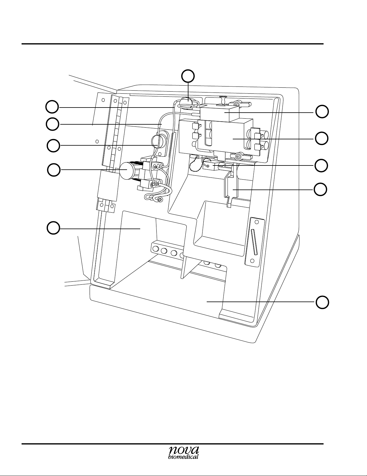
Figure 1.1 Analytical Compartment
1. Waste Line 7. Sampler
2. Reference Line 8. Air Detector
3. Pinch Valve (Reference) 9. Sensor Module with Sensors
4. Pump and Pump Tubing 10. Reference Electrode
5. Reagent Pack Opening 11. Pinch Valve (Waste)
6. Control Pack Opening
Page 21

1 System Identification Stat Profile pHOx Training Manual
NOTES:
1.2 Flow Overview
1.2.1 Reagents
Reagents are drawn from the reagent pack, through the reagent harness,
through the rotary valve, to the fluid fountain by way of the sample
tubing, where they are aspirated by the sample probe.
The sample probe can aspirate different reagents depending upon the
position of the rotary valve.
Aspirated fluids are drawn through the probe, the air detector, the
sensor module with sensors, reference electrode, around the pump and out
through the waste line to the waste container in the reagent pack.
1.3 Flow Components
1.3.1 Reagent Pack
The reagent pack contains 6 flexible bags in a cardboard carton. One
of these is a waste bag to collect the used reagents, controls, and
samples. The other 5 bags contain standard reagents: A, B, C, D, and
R. Each bag includes a polyethylene fitment with a septa seal. The
waste bag has a hydrophobic air vent.
Septa are arranged in a line along the rear of the pack. The septa are
pierced during insertion of the pack. The lot number and expiration
date are at the front of the pack.
The Reagent Management System (RMS) of the reagent pack automatically enters the calibration values, the lot number, the fluid
volumes, and the expiration date to the analyzer's computer after
insertion of the reagent pack.
Instructor shows all
these parts as they
are described.
Instructor points out
that the reagent pack
can be inserted and
removed a few times.
1-3
Page 22

1 System Identification Stat Profile pHOx Training Manual
NOTES:
1.3.2 Reagent Harness
The Reagent Harness transports reagents from the reagent pack to the
rotary valve. It is replaced as part of annual maintenance by Nova
Service.
1.3.3 Pinch Valves
There are 2 pinch valves: one is used to control the flow of the
reference fluid and the other one is used to control the flow of fluids
through the flow cell.
1.3.4 Peristaltic Pump
The pump is a 6-roller peristaltic pump driven by a stepper motor.
1.3.5 Sampler Assembly — Sample Probe
The sampler allows for the aspiration of the sample. The sampler has
2 sampling positions: horizontal for the aspiration of a sample from a
capillary tube and inclined for the aspiration of the sample from a
syringe. A capillary adapter automatically moves to the end of the
probe when the Capillary Analyze key is pressed. No special adapters
are required to aspirate a sample from a capillary tube. The capillary
or syringe positions are selected by pressing the Black Capillary key
or the White Syringe key.
1-4
Page 23

1 System Identification Stat Profile pHOx Training Manual
NOTES:
1.3.6 Sensor Module
The sensor module includes the preheater and flow cell. The preheater
preheats samples and controls to 37°C. In addition, it contains the
hematocrit impedance sensor and 2 air detectors. The sensor module
geometry is an interlaced configuration with the reference electrode
at the top of the sensor module, 3 sensors on the left side, 2 sensors on
the right side. In addition to the Hct sensor located in the preheater,
there are 6 sensors: Reference Electrode, Na+, PCO2, SO2 (optic), pH,
and PO2. A window in the door allows flow path visibility and is
augmented by a backlight.
1.3.7 Sensors
The Sensors housed in the sensor module are the core of the Stat
Profile pHOx Analyzer. The methodology used by each sensor are
Sensor Methodology
+
Na
Sodium ion-selective electrode
pH Hydrogen ion-selective glass electrode
PCO
PO
2
2
Severinghaus-type electrode
Polarographic Clark-type electrode
Hct Impedance electrode
Hb Impedance electrode/photometry
SO
2
Reflectance photometry (fiber optics)
The sensors clip into the sensor module, and an electrical contact is
automatically made.
1-5
Page 24
1 System Identification Stat Profile pHOx Training Manual
NOTES:
1.3.8 Reference Electrode
The Reference Electrode is mounted above the sensor module. It is a
solid-state Ag/AgCl electrode and provides the reference voltage for
comparison to sample voltages. The exit port of the flow path is
located on this electrode.
1.3.9 Sensor Blanks (PN 22507)
Sensor Blanks (see Figure 1.2) are used in place of sensors that are not
present on the analyzer or that are removed for certain maintenance and
troubleshooting procedures. Periodically (as needed) remove blanks
and clean the flow cell and tip of the blank with a cotton-tipped
applicator that is moistened with bleach.
DWG #7-0-039A
Figure 1.2 Sensor Blank
1.3.10Interconnect Tubing (PN 07161)
Interconnect Tubing is installed between the reference electrode and
the sensor module.
Required for the proper sealing of these components.
1.3.11Barometric Pressure Module
The Barometric Pressure Module, located on a printed circuit board,
continuously monitors the barometric pressure. This barometer can
be calibrated against an external barometer, if desired, through the
software.
1-6
Page 25
1 System Identification Stat Profile pHOx Training Manual
NOTES:
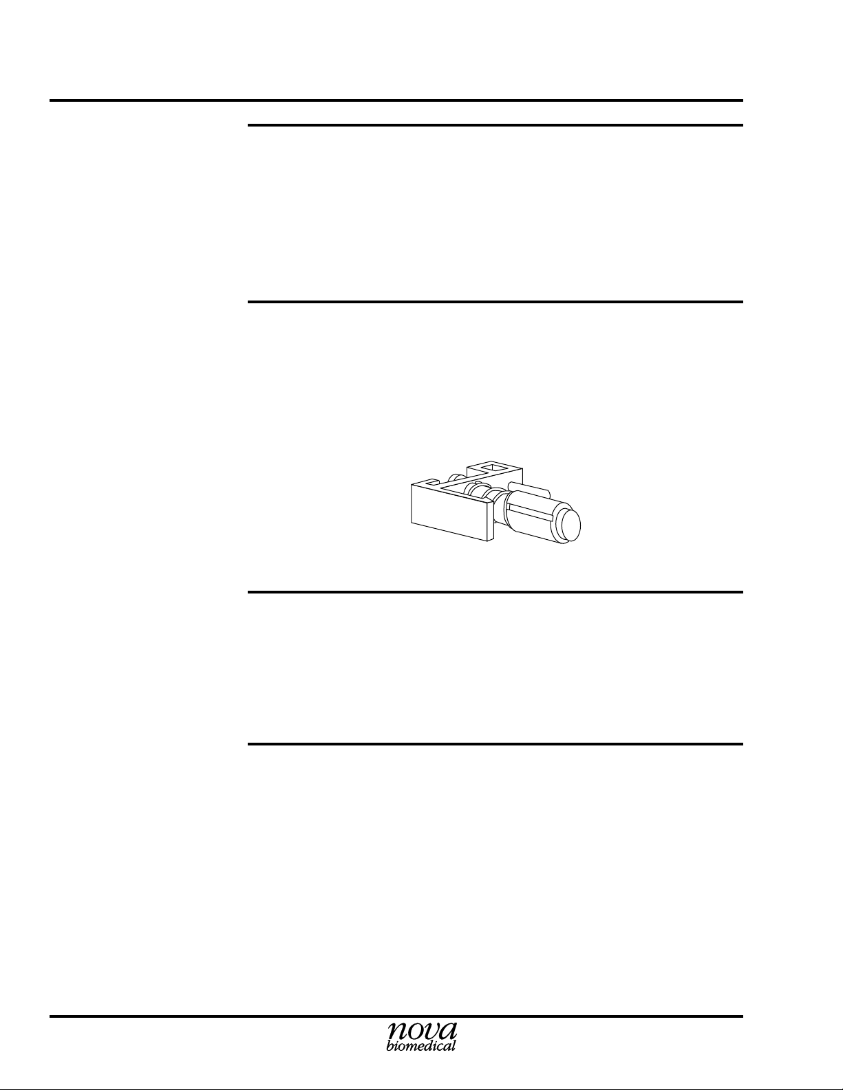
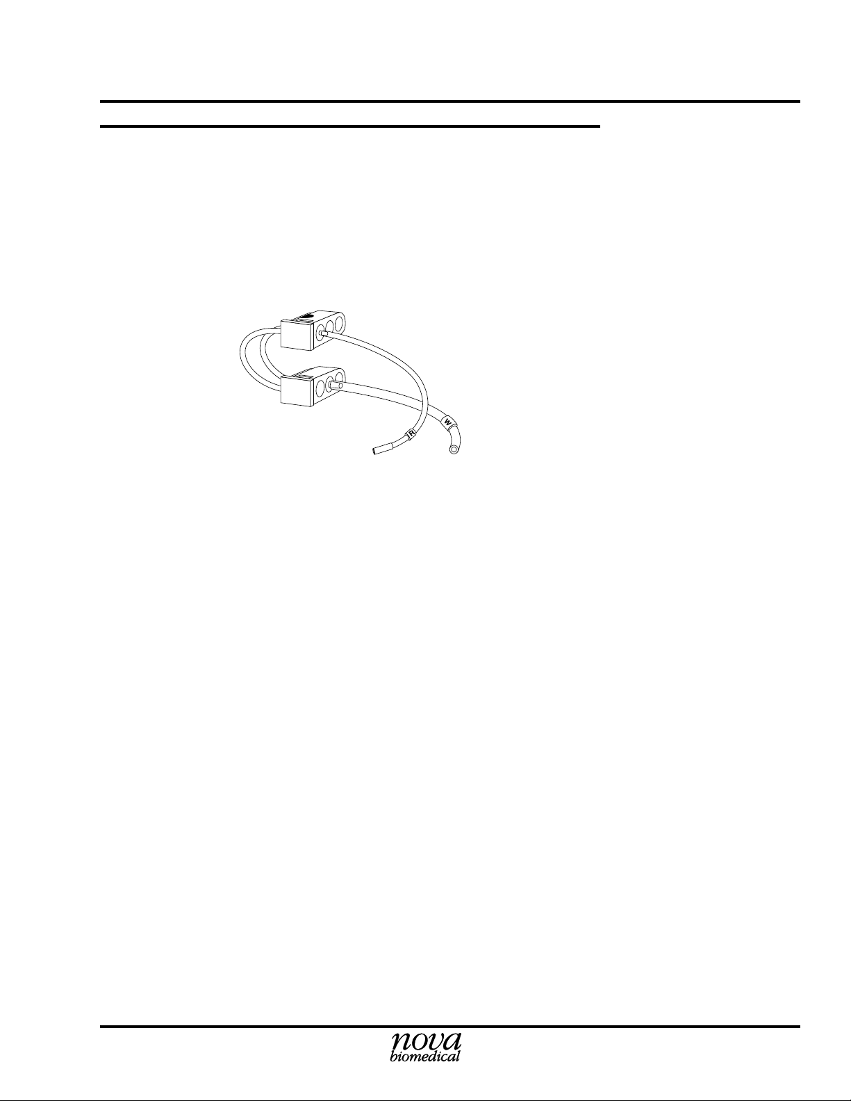
1.3.12Pump Tubing
The pump tubing has 2 manifolds (a top and bottom) and reference and
waste tubing, labelled R and W. The top manifold can be identified by
the half circle (right-sided). The R and W-pump tubing are connected
to the corresponding labeled outlets below the pump.
G #10-1007A
DW
Figure 1.3 Pump Manifolds and Tubing
1-7
Page 26

1 System Identification Stat Profile pHOx Training Manual
NOTES:
1-8
Page 27

2 Running an Analysis Stat Profile pHOx Training Manual
NOTES:
2 Running an Analysis
2.1 Is the Instrument Ready for Analysis?
2.1.1 Home Screen
Check the Home screen for Ready to analyze. The screen displays all
analytes with the uncalibrated ones x'd out. Also, the next QC and
Calibration times are displayed. A bar graph for the amount of
reagents and controls shows the approximate percent remaining.
For whole blood
2.2 Patient Samples — Acceptable Samples/Sample Handling
analysis only.
2.2.1 Acceptable Samples
The acceptable sample is heparinized whole blood.
Nova instruments are designed for clinical environments to analyze
actual patient specimens, not modified blood samples. Specimens
removed from the patient, anticoagulated appropriately, and promptly
analyzed are the only type of sample where the measurement results
will be reliable. Matrix effects/interferences can occur when patient
specimens are removed from the body, modified and then measured
on a Nova instrument. For example, matrix effects have been seen on
Nova analyzers when attempting to analyze samples collected from
cell savers used in various surgical procedures. Also, evaluation
laboratories run specimens from patients with a wide variety of
pathologies and from patients who are being treated with a broad
spectrum of therapeutic and pharmacological agents. Despite extensive clinical trials, it is not possible to anticipate every possible
combination of transfused blood products, crystalloids, and drugs (or
their metabolites) that may be present in a blood sample. As a result,
some users have found that their particular patient mix has necessitated making adjustments to maintenance. For example, a high
number of cardiopulmonary bypass pump or ECMO (extracorporeal
membrane oxygenation) samples result in a need for increased analyzer maintenance. If you are experiencing excessive downtime, you
may need to modify your own maintenance schedules. Nova’s Clinical Applications Group will assist you in tailoring a maintenance
program to meet these needs.
No serum or plasma
unless operator has
validated the system
for that purpose.
No urine, CSF,
cardioplegia solution,
or other body fluids.
Update to PN 24302 Rev. B 3/2002
2-1
Page 28

2 Running an Analysis Stat Profile pHOx Training Manual
NOTES:
This means no EDTA
(purple tops), NaF
(gray tops), or
uncentrifuged red
tops.
A general rule of thumb
for blood gas and
electrolyte analysis is
to run the sample
within 15 minutes of
the time it was
collected.
P
O2.... may increase in a
blood sample collected
into a plastic syringe
and stored on ice. The
NCCLS document
C32-P discusses
these increases.
2.2.2 Acceptable Anticoagulants
Sodium and lithium heparin resulting in a final concentration of not more
than 20 I.U. per mL in blood are the only acceptable anticoagulants.
2.2.3 Syringe Handling Tips
1. Remove air at time of collection.
2. Mix sample thoroughly by rolling between hands.
3. Run as soon as possible after collection. Do not ice plastic
syringes.*
4. Check for clots by expelling a drop of blood onto a gauze
pad.
5. For repeat samples, expel any air left in syringe.
6. Position sample so that probe tip stays deep in the syringe
but not touching the syringe plunger.
* NCCLS. Nov., 1993. Considerations in the simultaneous measurement of blood gases,
electrolytes and related analytes in whole blood., NCCLS document C32-P. Vol. 13, No. 17.
2-2
Page 29
2 Running an Analysis Stat Profile pHOx Training Manual
NOTES:
2.2.4 Capillary Handling Tips
• Collect in heparinized capillary tubes only.
• Place metal “flea” (stirring bar) in capillary prior to collecting sample.
• Sample must be collected without air spaces or gaps in
capillary.
• Using magnet, mix well after collection.
• Cover tube ends with removable caps (not clay seal) for
transportation to lab.
• See additional notes in Chapter 1 of the Reference Manual.
2.2.5 Sample is Presented and Analysis Occurs
Press the White Button (Syringe) or the Black Button (Capillary) to
run an analysis. The Aspirate screen displays. Wait until the sample
probe is in position. Present the sample to the probe.
Instructor
demonstrates
analysis.
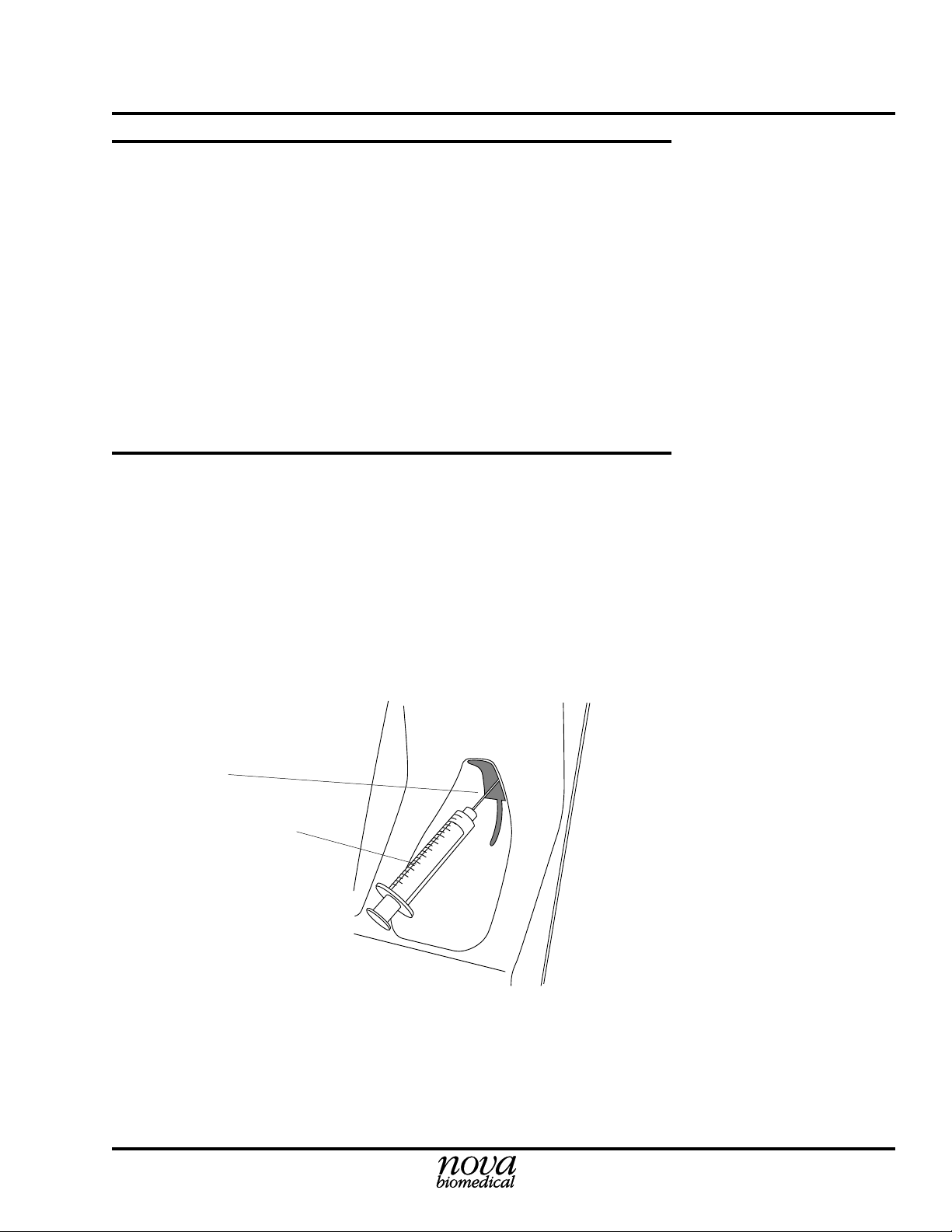
Samples can be presented in a syringe, opened vacuum tube, sample
cup, or capillary.
Probe
Syringe
G #10-1024A
DW
Figure 2.1 Syringe Sample Presentation
2-3
Page 30

2 Running an Analysis Stat Profile pHOx Training Manual
NOTES:
After the sample is positioned, press Continue (soft Key). (If not
pressed within 45 seconds, the analyzer returns to the Ready screen.)
In STAT Mode
Analysis, the Sample
Information screen is
not displayed. The
ABG ResultsMeasured screen is
displayed after
aspiration is
completed.
If the view results soft
key is not selected the
analysis will not go to
completion. No results
will be displayed or
printed out.
NOTE:
If you attach an
external key board,
alpha keys are
available.
2.3 Sample Information
2.4 Results Screen and Printout
The pump turns, pulling the sample through the probe, air detector
tubing, and sensor module. A pop-up screen appears. Remove the
sample from the probe. Press Analyze. (If Analyze -soft key- is not
pressed within 30 seconds, the probe will automatically move downward.) The probe moves downward.
The analyzer displays the Sample Information screen with a bar graph
until completion.
Input sample information, then press View Results to see the completed results.
The Sample information screen is displayed after aspiration has been
completed. This screen allows you to enter Accession number,
Operator ID, Patient ID number, Combine with CO-Oximeter, combine with last sample for A/V & Shunt results, Patient temperature,
and Sample Type. Use arrow keys to move to next option; Use the
number keys or the Enter key to toggle or get pop-up selection.
2-4
The ABG Results -Measured screen is displayed and results fill in the
table as they become available. The results on the screen can be
printed by pressing Print (soft key). Press Next Page (soft key) to go
to the next results screen, etc.
2.5 Running an Analysis Exercise
See Running an Analysis Checklist to perform the lab.
2.6 Standby Mode
See Standby Mode Checklist to perform the lab.
Page 31

2 Running an Analysis Stat Profile pHOx Training Manual
Running a Syringe Analysis Checklist
NOTES:
Step 1 Check the instrument for readiness.
• Check the display for the Home (Ready) screen.
Step 2 Present sample and begin analysis.
(Procedure for syringes)
• Press the White Syringe Button.
• Probe positions for sample aspiration.
Slide the syringe tip over the extended probe.
CAUTION:
the base of the syringe plunger or the bottom of the
sample cup or tube.
Do not allow the sample probe to touch
Step 3 Analysis begins.
• Press Aspirate Normal (soft key) to start the sampling. (Or,
press Aspirate Micro (soft key) for a smaller sample: 45µL
instead of 70µL.)
NOTE:
5 minutes of the time the probe extends, the probe
automatically starts to move down.
• When the system signals by an audible alarm, withdraw the
sample.
• Press Analyze. The probe moves down.
NOTE:
after the sample has been aspirated, the probe
automatically starts to move down.
If one of these soft keys is not pressed within
If Analyze is not pressed within 30 seconds
• The analysis begins.
• The Sample information screen is displayed.
Update to PN 24302 Rev. B 3/2002
2-5
Page 32

2 Running an Analysis Stat Profile pHOx Training ManualRunning a Syringe Analysis Checklist
NOTES:
Step 4 Enter patient information.
• The Sample information screen is displayed. (If in STAT
Mode, this screen does not display. Go to next step.)
• Enter patient data.
NOTE:
Press arrow keys to move through options.
Press number keys or Enter key to toggle or get
pop-up screen.
If the View Results
(soft key) is not
pressed, the analysis
will not go to
completion and will not
print out the results.
Step 5 Results are displayed and printed.
• Press View Results (soft key) to view the results.
• Measured results are displayed on the ABG Results Measured screen as they become available.
Selected calculated results can be viewed by pressing
Next Page (soft key) from the Results screen.
• To print the results, press Print (soft key).
• Results are transmitted to an optional external printer or
computer, if enabled.
• After transmission and/or printout, all patient information
becomes READ ONLY. They no longer can be changed or
combined.
• Press Home (soft key) to return to the Home (Ready) screen.
2-6
Page 33

2 Running an Analysis Stat Profile pHOx Training Manual
Running a Capillary Analysis Checklist
NOTES:
Step 1 Check the instrument for readiness.
• Check the display for the Home (Ready) screen.
Step 2 Prepare capillary.
(See Section 2.2.4, Capillary Handling Tips)
• Mix sample again by drawing magnet back and forth along
the length of the capillary.
• Keeping capillary level, remove cap (or caps) from the ends.
• Remove mixing flea by pulling it out one of the free ends
with the magnet.
Step 3 Present sample.
• Press the Black Capillary Button and wait for probe to
position.
• Holding one gloved finger over the open end of the capillary, carefully slide the tip of the capillary into the adapter
until it just touches the probe.
• The capillary should be in line with probe, not tilted horizontally.
Demo this before
trainees attempt it.
Skip this section if
they do not run
capillaries.
CAUTION: Do not
end of the capillary yet.
Step 4 Begin analysis.
• Press Aspirate Normal (soft key) to start the sampling. (Or,
press Aspirate Micro (soft key) for a smaller sample: 45µL
instead of 70µL.)
NOTE:
5 minutes of the time the probe extends, the probe
automatically starts to move down.
• As soon as the pump starts to turn, remove your finger from the
open end of the capillary, allowing the sample to be drawn up.
Update to PN 24302 Rev. B 3/2002
If one of these soft keys is not pressed within
remove your finger from the open
2-7
Page 34

2 Running an Analysis Stat Profile pHOx Training Manual
NOTES:
Running a Capillary Analysis Checklist
• When the system signals by an audible alarm, remove the
capillary from the probe and adapter.
• Press Analyze. The probe moves down.
NOTE:
after the sample has been aspirated, the probe
automatically starts to move down.
• The analysis begins.
• The Sample information screen is displayed.
If Analyze is not pressed within 30 seconds
Step 5 Enter patient information.
• The Sample information screen is displayed. (If in STAT
Mode, this screen does not display. Go to next step.)
• Enter patient data.
NOTE:
Press arrow keys to move through options.
Press number keys or Enter key to toggle or get
pop-up screen.
Step 6 Results are displayed and printed.
If the View Results
(soft key) is not
pressed, the analysis
will not go to
completion and will not
print out the results.
• Press View Results (soft key) to view the results.
• Measured results are displayed on the ABG Results Measured screen as they become available.
Selected calculated results can be viewed by pressing
Next Page (soft key) from the Results screen.
• To print the results, press Print (soft key).
• Results are transmitted to an optional external printer or
computer, if enabled.
• After transmission and/or printout, all patient information
becomes READ ONLY. They no longer can be changed or
combined.
• Press Home (soft key) to return to the Home (Ready) screen.
2-8
Page 35

2 Running an Analysis Stat Profile pHOx Training Manual
Running an AV Shunt Analysis Checklist
NOTES:
Step 1 Check the instruments for readiness.
NOTE:
This checklist can only be performed if a
Nova CO-Oximeter is in communication with the
pHOx Analyzer, so that the results can be combined. This checklist may be removed if not needed.
• Check the pHOx display for the Home (Ready) screen.
• Check the CO-Oximeter for readiness.
(See the Nova CO-Oximeter Reference Manual.)
Step 2 Present sample and begin analysis.
• Press the White Syringe Button.
Probe positions for sample aspiration.
• Press the AV Shunt (soft key).
• Position the mixed venous sample over the extended probe.
You must press soft
CAUTION:
the base of the syringe plunger or the bottom of the
sample cup or tube.
Do not allow the sample probe to touch
keys within 45
seconds or the cycle
will abort
automatically.
Step 3 Analysis begins.
• Press Aspirate (soft key).
• When the system signals by an audible alarm, withdraw the
sample.
• Press Analyze (soft key). The probe moves down.
• The analysis begins.
• The Sample information screen is displayed; enter patient
data.
NOTE:
Press arrow keys to move through options.
Press number keys or Enter key to toggle or get
pop-up screen.
If Analyze is not
pressed within 30
seconds after the
sample has been
aspirated, the probe
automatically starts
to move down.
2-9
Page 36

2 Running an Analysis Stat Profile pHOx Training Manual
NOTES:
Running an AV Shunt Analysis Checklist
Step 4 Continue Analysis on CO-Oximeter.
• Analyze the mixed venous sample on the CO-Oximeter.
Step 5 Run the Arterial Sample.
• When the message, Mixed Venous sample complete, position the arterial sample over the extended probe.
• Press Aspirate (soft key).
• After aspiration, remove arterial sample and press Analyze
(soft key).
Step 6 Continue Analysis on CO-Oximeter.
If the View Results
(soft key) is not
pressed, the analysis
will not go to
completion and will not
print out the results.
• Analyze the arterial sample on the CO-Oximeter.
Step 7 Results are displayed and printed.
• Press View Results (soft key) to view the results.
• Measured results are displayed on the ABG Results Measured screen as they become available.
Selected calculated results can be viewed by pressing
Next Page (soft key) from the Results screen.
• To print the results, press Print (soft key).
• Results are transmitted to an optional external printer or
computer, if enabled.
• After transmission and/or printout, all patient information
becomes READ ONLY. They no longer can be changed or
combined.
• Press Home (soft key) to return to the Home (Ready) screen.
2-10
Page 37

2 Running an Analysis Stat Profile pHOx Training Manual
Standby Mode Checklist
NOTES:
Step 1 Start the procedure.
NOTE:
This option allows you to place the analyzer
into a standby mode and allows you to reactivate
the analyzer out of the mode at a programmed time
and date. The standby mode will use less reagents
and controls because the analyzer will not run its
automatic calibration cycles. Calibration is lost
SO
except for
set time is elapsed, if you initiate a calibration, or if
you turn Standby off.
• From the Operational Menu, scroll down to the Standby
Mode.
• Press ENTER (once if mode is OFF or twice if Mode is ON).
and Hb. Standby mode ends after the
2
Step 2 Set the date.
• Press ENTER (again) - the date becomes blank.
• Key in the date that you want the analyzer to come out of
Standby Mode.
• Press ENTER to set the date. (DO NOT press OK.)
Step 3 Set the time.
• Press any Arrow key to go to the time field.
• Press ENTER - the time becomes blank.
• Key in the time that you want the analyzer to come out of
Standby Mode.
• Press ENTER to set the time. (DO NOT press OK.)
2-11
Page 38

2 Running an Analysis Stat Profile pHOx Training Manual
NOTES:
Standby Mode Checklist
Step 4a Start the Standby Mode.
• Now press OK (soft key) to initiate the Standby Mode.
• Another pop-up screen appears to verify that you want to go
into Standby Mode. Press OK (soft key) again and the
Standby Mode is officially ON.
Step 4b Cancel the Standby Mode.
• Press Cancel (soft key) to cancel the Standby Mode.
• The date and time fields revert to the previous settings.
• The Standby Mode is now OFF.
2-12
Page 39

3 Operational Status Stat Profile pHOx Training Manual
NOTES:
3 Operational Status
3.1 Home Screen - Ready for Analysis
Indicates readiness of the analyzer.
• All analytes are shown. Uncalibrated analytes are x'd out and
a — (a line through an analyte prefix) when the channel did
not pass QC and QC lockout is enable.
• The Next Cal and if programmed the Next QC is displayed.
• Two fluid gauges display the approximate remaining solutions for the reagent cartridge and control cartridge.
3.2 Questionable Results
Results with a problem display a symbol in the Alert column. There
are a number of symbols that can appear after the results. The symbols
have the following meanings:
• ↑ (single up arrow), ↓ (single down arrow) - The result is higher or
lower than the defined reference range for the parameter.
• ↑↑ (double up arrow), ↓↓ (double down arrow) - The result is higher
or lower than the defined alert range for the parameter.
• ↑↑↑ (triple up arrow), ↓↓↓ (triple down arrow) - The result is out of
the analyzer's operating range.
• X (an X through an analyte prefix) - The channel is uncalibrated.
• ? (question mark) - Insufficient sample is detected during sample
reading.
• * (asterisk) - The result is calculated using a default sodium
concentration.
• — (a line through an analyte prefix) - The channel did not pass QC and
QC lockout is enabled; or the results have been suppressed.
3.3 System Status Screen
This screen only appears if there are operational messages or status
codes.
3-1
Page 40

3 Operational Status Stat Profile pHOx Training Manual
NOTES:
3-2
Page 41

4 Calibrating the Analyzer Stat Profile pHOx Training Manual
NOTES:
4 Calibrating the Analyzer
4.1 Full 2-Point Calibration - all except Hb and
• Uses internal calibrators (standards)
• Calculates slopes for sensors and air detectors
• Occurs at regular intervals or can be manually initiated by
pressing Calibrate (soft key)
• Included as part of most maintenance routines
• Resets calibration timers
• Can generally be stopped by pressing Exit (soft key)
• Can be manually run by pressing the Calibration (soft key)
from the Ready (or Not Ready) screen.
1. The 2 pt. Calibration screen will display.
2. Select option 1: pH, PCO2, PO2, Hct Calibration (ABG).
3. Press Enter.
4.2 Calibration Timing
Auto calibration takes place at intervals of 2, 4, or 6 hours depending
on analyzer activity. See Chapter 3 of the Reference Manual for more
details.
S
O
2
4-1
Page 42

4 Calibrating the Analyzer Stat Profile pHOx Training Manual
NOTES:
4.3 Other Types of Calibration
4.3.1SO2 and Hb Calibration
• Uses external calibrators (2 levels)
• Initiated by the operator monthly or as needed
• Access from Ready screen: Calibrate (soft key)
Instructor shows
Calibration
Configuration screen
for calibration options.
Access the Setup
Menu (Password),
select Operation
Configuration Menu
(press Enter). Select
the Calibration
Configuration option
(press Enter). Discuss
the options.
CLIA regs. require 30
minutes.
4.3.2 Single Point Calibration for Non-Gas Sensors
• Values for calibration (standards) are lot specific and must
be verified or reentered at time of calibration.
S
O
See Calibrating
• Occurs with each gas Cal I (30-45 min. intervals) if Mode A
is selected
• Occurs with each analysis if Mode B is selected
• Uses a calibration standard (either C or A) and increases
time to appearance of results
• Checks for sensor drift
• Printing of drift is operator selected.
and Hb Checklist.
2
Mode A: One point
fluid & Gas Cal done
every 30-45 minutes.
Mode B: One point fluid
& Gas Cal done with
EACH analysis.
4-2
Page 43

4 Calibrating the Analyzer Stat Profile pHOx Training Manual
Calibrating SO2 Checklist
NOTES:
Step 1 Begin calibration.
• From the Home (Ready) screen, press Calibrate (soft key).
• Then select option 2: External two standard Hb,
Calibration then press ENTER.
• The External Standard Hb, SO2% Calibration screen appears.
SO
%
2
Step 2 Verify calibrator (standard) values.
• Consult insert sheet for this lot and compare to values on the
screen.
• Key in the assay value for Std. #1, if necessary.
Step 3 Prepare calibrator #1.
• Mix gently by inversion.
• Open the ampule carefully to avoid injury (glass edges).
• Position Calibrator #1 so that the extended probe tip is well
covered by the solution.
• Press Continue (soft key).
• When system signals by audible alarm, remove the ampule,
• Press Analyze (soft key).
Step 4 Prepare calibrator #2.
• Repeat procedure for calibrator #2.
• Enter/verify assay value for Std. #2. (Press ENTER after
entering the assay value.)
• Mix gently by inversion.
• Open the ampule carefully to avoid injury (glass edges).
• Position Calibrator #2 so that the extended probe tip is well
covered by the solution.
• Press Continue (soft key).
• When system signals by audible alarm, remove the ampule,
• Press Analyze (soft key).
4-3
Page 44

4 Calibrating the Analyzer Stat Profile pHOx Training Manual
NOTES:
4-4
Page 45

5 Using and Handling Controls Stat Profile pHOx Training Manual
NOTES:
5 Using and Handling Controls
5.1 Controls
CAUTION:
of controls other than Nova controls and will void warranty on
components that come into contact with them.
The Stat Profile pHOx Analyzer has on board QC and on board
controls. Controls can be analyzed either with the internal control
pack or with external Nova control ampules.
Performance of the analyzer may be affected by the use
5.1.1 Stat Profile pHOx Controls
• Monitor performance of all blood gases and electrolytes
• Contain no preservatives, dyes, or surfactants that can
damage sensors or other flow components
• Formulated at 3 clinically significant levels:
L1 Acidosis, with low pH, high PCO2, low PO2, low SO2,
low normal Hct and low normal Hb values
L2 Normal, with normal pH, PCO2 and PO2 values
L3 Alkalosis, with high pH, low PCO2, high PO2 high
SO
, and normal high Hct/Hb values
2
• Internal in a self-containing control pack (Auto- Cartridge
QC) or external in individual ampules
The Auto- Cartridge
QC has a use-life of 35
days.
5.2 Handling Controls
5.2.1 Storage Temperature
Store at 25°C (77°F). Warmer or colder controls affect gases and pH.
Hold vial between thumb and fingertip when shaking to avoid
changing temperature. For every 1°C
1%. The opposite effect is seen at temperatures
CAUTION:
sill or near a heating or air-conditioned duct.
Do not refrigerate. Avoid storing controls on a window
above
25°C, PO2 recovery drops
below
25°C.
5-1
Page 46

5 Using and Handling Controls Stat Profile pHOx Training Manual
NOTES:
5.2.2 Stability of Opened Ampules
Shake and analyze within 30 seconds of opening. Contamination with
room air will begin to affect PO2, PCO2, and pH results after that time.
PO
Room air has a
Exposure of controls to room air causes:
PCO
to decrease.
2
5.2.3 Altitude and Barometric Pressure Effects
Aqueous controls are assayed at sea level. Changes in altitude will affect
gas recovery. For every 1000 ft above sea level, PO2 recovery drops by
approximately 0.5%. An incorrect barometric pressure will also affect
gas recovery. System barometric pressure is displayed on the printout,
barometric pressure, or Status screen. If significantly different from a
known, accurate measurement, enter an offset by selecting Setup, enter
password, select Operations Configuration, press Enter, select System
Configuration Menu (use arrow keys to go to corrected Barometric
Pressure), enter mmHg, Press Home to exit to Home (Ready) screen.
of about 150 mmHg and a PCO2 of ~0 mmHg.
2
PO
and pH to increase,
2
5.3 When to Use
As of the date of publication of this guide, a minimum of one blood
gas control must be analyzed every 8 hour shift of lab operation. Also,
after maintenance or troubleshooting or as required by the laboratory’s
quality control program. All levels must be analyzed within a 24 hour
period.
5.4 Using the Stat Profile pHOx's On-Board QC Features
The analyzer's QC features allow you to:
• Set ranges and units for acceptable results.
• Store statistics.
• Program for internal or external control source.
• Display or print QC statistics in the form of reports.
• Remind or require operators to run QC at specific intervals.
• Analyze other forms of QC such as proficiency surveys or
linearity standards without “offsets”.
5-2
Page 47

5 Using and Handling Controls Stat Profile pHOx Training Manual
NOTES:
These features must be enabled or setup before they can be used. See
Quality Control Setup in the analyzer’s reference manual for details. If
you will be using them, the installer will have done at least a partial
setup so that you can learn how they work.
5.4.1 The QC Soft key
This key has more than one function:
• To run a QC analysis either internal or external
• To view or to print QC data
• To set up QC levels
• To turn automatic QC analysis on or off
5.4.2 Automatic QC Analysis (Internal)
To use the Automatic QC Analysis feature properly, the QC analysis
times need to be programmed under the Daily Analysis Times screen
during the QC Setup and the Automatic QC Analysis needs to be
turned on. QC is automatically performed at these programed times
with the controls from the Auto-Cartridge QC.
NOTE:
Internal QC can also be run manually: see the checklist.
5.4.3 Manual QC Analysis (External)
To use the Manual QC Analysis feature properly, the QC analysis
times need to be programmed under the Daily Analysis Times screen
during the QC Setup and the Automatic QC Analysis needs to be
turned on. When QC analysis is needed, a Pop up screen will appear
prompting you to run the required QC. Press OK (soft key). Then go
to the Analyze QC screen and select the appropriate QC.
GO TO CHECKLIST.
5-3
Page 48

5 Using and Handling Controls Stat Profile pHOx Training Manual
DWG #6010A
NOTES:
Analyzing Controls Checklist
Step 1 Preparing for Analysis
• Hold QC ampule between thumb
and forefinger and agitate vigorously for several seconds.
NOTE:
Do not warm ampule in hands.
Step 2 Initiating the QC Analysis
• Press QC (soft key) on the Home screen.
• With Analyze QC Highlighted, press ENTER.
• Select the QC to be analyzed, i.e., QC Level #1 External.
• Change if necessary by pressing Previous Control (soft key)
or Next Control (soft key).
• Press the White Button (Syringe) or Analyze (soft key).
Step 3 Completing the Cycle
Figure 5.1 Agitating the Ampule
5-4
• Once probe has extended, open the ampule while protecting
yourself from the sharp glass edges.
• Fully immerse the probe into the fluid of the ampule. Do not
allow the probe to touch the bottom of the ampule.
• Press Continue (soft key).
• When the system signals by an audible alarm, remove the
ampule and press Analyze (soft key). The probe moves
downward.
• Discard the ampule.
NOTE:
cause the system to
to the Quality Control screen.
Failure to press Continue (soft key) within 45 seconds will
time-out
canceling the cycle and returning you
Page 49

5 Using and Handling Controls Stat Profile pHOx Training Manual
Analyzing Controls Checklist
NOTES:
Step 4 Accepting or Rejecting Results
When results are ready, they appear on the screen along with
an indication of whether they have passed or failed the QC
range check. If one or more tests are out of range, the QC
Results screen flashes Exceed Limits.
• To save all data, press QC (soft key).
• To reject the data, press Delete (soft key). Then press
Continue to discard all the data.
• All data is either accepted or rejected.
Step 5 Repeat for next level
5-5
Page 50

5 Using and Handling Controls Stat Profile pHOx Training Manual
NOTES:
Analyzing Internal Controls Checklist
Step 1 Preparing for Analysis
• From the Ready screen, press QC (soft key) on the Home
screen.
Step 2 Initiating the QC Analysis
• With Analyze QC Highlighted, press ENTER.
• Select the QC to be analyzed, i.e., QC Select Internal L1.
• Change if necessary by pressing Previous Control (soft key)
or Next Control (soft key).
• Press Analyze (soft key).
Step 3 Accepting or Rejecting Results
When results are ready, they appear on the screen along with
an indication of whether they have passed or failed the QC
range check. If one or more tests are out of range, the QC
Results screen flashes Exceed Limits.
• To save all data, press QC (soft key).
• To reject the data, press Delete (soft key). A pop-up screen
appears: enter your password. Then press Continue to discard all the data.
• All data is either accepted or rejected.
Step 4 Repeat for next level
5-6
Page 51

5 Using and Handling Controls Stat Profile pHOx Training Manual
NOTES:
5.5 QC Data
To view QC data, select View or Print QC Data on the Quality Control
(QC) screen then press Enter. The QC Data screen for the selected
level is displayed. From this screen, you can view today's data, daily
statistics, monthly statistics, cumulative, or Levey-Jennings.
5.5.1 View Today's Data
From the QC Data screen, select View Today's Data then press Enter.
The QC Results screen is displayed. To view the next result, press
Next Page (soft key). For options, press Options (soft key). A pop-up
window appears. One option is for deleting this result. You can also
print or view other statistics.
5.5.2 View Daily Statistics
From the QC Data screen, select View Daily Statistics then press
Enter. This screen is the QC Daily Statistics for the selected level.
From this screen, you can view the next level, and/or print the
statistics.
5-7
Page 52

5 Using and Handling Controls Stat Profile pHOx Training Manual
NOTES:
5.5.3 View Monthly Statistics
The Monthly Statistics is a record of all QC accepted for the past month.
Print this record for your files at the end of each calendar month.
1. From the Quality Control screen, select View or Print QC Data.
2. From the QC Data screen select View monthly statistics.
3. Press Print (soft key).
=======Stat profile QC Statistics======
Date 6-23-98 Time 10:54
Analyzer ID 0 Operator ID 1
Lot#1234567890 Exp 7-31-98
----------------------------------------------------
DAILY (n=6)
Test Mean ±Range SD CV
pH 7.595 0.050 2.3 2.3
pCO223.0 10.0 2.3 2.3
pO
SO
Hb 7.5 10.0 3.5 3.5
Hct 18 10.0 2.3 2.3
----------------------------------------------------
Test Mean ±Range SD CV
pH 7.595 0.050 2.3 2.3
pCO223.0 10.0 2.3 2.3
pO
SO
Hb 7.5 10.0 3.5 3.5
Hct 18 10.0 2.3 2.3
----------------------------------------------------
QC CUMULATIVE (n=1,498 during163 days)
Test Mean ±Range SD CV
pH 7.595 0.050 2.3 2.3
pCO223.0 10.0 2.3 2.3
pO
SO
Hb 7.5 10.0 3.5 3.5
Hct 18 10.0 2.3 2.3
----------------------------------------------------
155 12.0 1.0 1.0
2
.... .... .... ....
2
MONTHLY (n=97 during 30 days)
155 12.0 1.0 1.0
2
.... .... .... ....
2
155 12.0 1.0 1.0
2
.... .... .... ....
2
5-8
Figure 5.2 QC Statistics Printout
Page 53

5 Using and Handling Controls Stat Profile pHOx Training Manual
NOTES:
5.5.4 Printing Levey-Jennings Charts
The Levey-Jennings data graph is displayed on screen. When printing, each graph will be rotated 90° with the date appearing on the long
axis of the chart.
1. From the Quality Control screen, select View or Print QC Data.
2. From the QC Data screen, select View Levey-Jennings.
3. Highlight the analyte using the arrow key.
4. Press enter to view data on the screen.
5. Press Print (soft key).
=======Stat profile QC Statistics======
LEVEY-JENNINGS CHARTS
Analyzer ID 0 Operator ID ...
Lot # 1234567890 Exp Date 07-31-98
Date Lower Limit Upper Limit
----------------------------------------------------
7.585 7.600 7.635
---------------------------------------------------11-23 *
11-24 *
11-25 *
11-26 *
11-27 *
11-28 *
11-29 *
11-30 *
12-01 *
12-02 *
Figure 5.3 Levey-Jennings Graphs Printout
5-9
Page 54

5 Using and Handling Controls Stat Profile pHOx Training Manual
NOTES:
5-10
Page 55

6 Replacing Reagents & Paper Stat Profile pHOx Training Manual
NOTES:
6 Replacing Reagents and Paper
6.1 When to Replace
Replace the fluid pack and/or the control pack when it has reached its
expiration date or when the graphic appears empty on the Home
screen. Also, replace the capillary adapter found in the reagent pack.
6.2 How to Replace
To install a new reagent pack and/or control pack, you will be using one
of the automated Operational Menu procedures: Change Reagent Pack
or Change Control Pack. These procedures come up as screens with
the steps necessary to carry out the changing of the pack. Because the
reminders are brief, you should refer to the complete illustrated procedures located in the maintenance section of the analyzer's reference
manual if you need additional details. To stop automated maintenance
procedures, press Cancel (soft key).
The on-board Reagent
Cartridge has a use-
life of 45 days.
The on-board QC
Cartridge has a use-
life of 35 days.
6.3 Replacing the Reagent Pack
See Replacing the Reagent Pack Checklist to perform the lab.
6.4 Replacing the Control Pack
See Replacing the Control Pack Checklist to perform the lab.
6.5 Replacing the Printer Paper
See Replacing the Printer Paper Checklist.
6-1
Page 56

6 Replacing Reagents & Paper Stat Profile pHOx Training Manual
NOTES:
Replacing the Reagent Pack/Capillary Adapter Checklist
WARNING: Blood samples and blood products are potential sources of
hepatitis and other infectious agents. Handle all blood products and
flow path components (waste-line, septum assembly, probe, flow cell,
etc.) with care. Gloves and protective clothing are recommended.
Dispose of the reagent waste bottle according to your laboratory's
biohazardous waste policies.
Step 1 Replace the capillary adapter.
• From the Home (Ready) screen, press Menu.
• Select Change Pack.
• Press Enter. A pop-up screen appears.
Change Reagent Pack
Change Control Pack
Exit
• Highlight Reagent Pack.
• Press Enter.
• Press Move Probe (soft key).
• Open the door.
• Remove the capillary adapter from the front of the probe by
pulling it off.
• Replace the adapter with a new one found in the reagent
pack. As you put on the adapter, make sure the probe goes
into the center hole of the adapter.
• Press Move Probe (soft key) when finished.
• Press Cancel then press Cancel again to return to the Home
screen.
6-2
Step 2 Remove old cartridge.
• Open the door.
• Remove the old cartridge - lift the cartridge up slightly to
clear the lip.
• Mix the new cartridge by gently inverting for several seconds.
DO NOT SHAKE THE PACK.
• Slide in the new cartridge.
• Close the door.
Update to PN 24302 Rev. B 3/2002
Page 57

6 Replacing Reagents & Paper Stat Profile pHOx Training ManualReplacing the Reagent Pack/Capillary Adapter Checklist
Step 3 Prime the analyzer.
• Press Prime (soft key): this primes and validates the cartridge.
Step 4 Calibrate the analyzer.
• After priming, a pop-up screen appears with a question, "Do
you want to recalibrate? Yes or No." Press Yes (soft key).
• Calibration takes place.
Step 5 Validate performance with QC.
• Run QC.
• Document the results.
NOTES:
6-3
Page 58

6 Replacing Reagents & Paper Stat Profile pHOx Training Manual
NOTES:
Replacing the Control Pack Checklist
WARNING: Blood samples and blood products are potential sources of
hepatitis and other infectious agents. Handle all blood products and
flow path components (waste-line, septum assembly, probe, flow cell,
etc.) with care. Gloves and protective clothing are recommended.
Dispose of the reagent waste bottle according to your laboratory's
biohazardous waste policies.
Step 1 Initiate the procedure
• From the Home (Ready) screen, press Menu.
• Select Change Pack.
• Press enter. A pop-up screen appears.
Change Reagent Pack
Change Control Pack
Exit
• Highlight Control Pack by using the down arrow key.
• Press Enter.
Step 2 Follow the screen directions.
• Open the cover.
• Remove the old cartridge - lift the cartridge up slightly to
clear the lip.
• Mix the new cartridge by gently inverting for several seconds.
DO NOT SHAKE THE PACK.
• Slide in the new cartridge.
• Close the door.
Step 3 Prime the analyzer.
• Press Prime (soft key).
Step 4 Calibrate the analyzer.
• After priming, a pop-up screen appears with a question, "Do
you want to recalibrate? Yes or No." Press Yes (soft key).
• Calibration takes place.
6-4
Step 5 Validate performance with QC.
• Run QC.
• Document the results.
Update to PN 24302 Rev. B 3/2002
Page 59

6 Replacing Reagents & Paper Stat Profile pHOx Training Manual
Replacement of the Printer Paper Checklist
NOTES:
Step 1 Open the printer cover.
Step 2 Lift print head.
• Open the printer platen.
• Gently pull the lever near the paper advance knob forward.
• Remove the depleted roll of paper.
Step 3 Remove paper holder from the old roll of paper.
Step 4 Install new roll of paper.
• Insert the paper holder into
a new roll of paper. The
loose end of the paper
should feed from the bottom of the roll.
• Install the paper holder with
paper into the support collars.
• Push the paper through the
back of the roller.
Step 5 Reposition print head.
DWG #10-1002B
Platen
Paper Advance
Knob
Figure 6.1 Paper Installation
• Center the paper and close the printer platen by moving the
lever back to the original position.
• Advance the paper by using the paper advance knob.
• Feed the paper through the cover. Then close the cover.
6-5
Page 60

6 Replacing Reagents & Paper Stat Profile pHOx Training Manual
Replacement of the Printer Paper Checklist
NOTES:
Step 6 Test printer (Optional).
• From the Home screen, press Menu (soft key); press Service
(soft key); use the down arrow key to select Printer Menu:
press ENTER; use the down arrow key to select Character
Set Test; finally press ENTER to obtain a character printout
to verify proper operation (see Figure 6.2).
• After the self test is completed, a pop-up screen appears.
Press OK.
• Press Home (soft key) to return to the Home screen
** TEST PRINT **
!”#$%&’()*+,-./01234567
89:;<=>?@ABCDEFGHIJKLMNO
PQRSTUVWXYZ[\]
hijklmnopqrstuvwxyz{|}~
^
‘abcdefg
—
ЗьйвдаезклипомДЕ
ЙжЖфцтыщяЦЬ¢£¥ ƒбнуъсСao
1
¿
αβΓπΣσµτΦθΩδ∞φ∈
≡±≥≤ ÷≈°.−
DWG #9-1000A
1
〈〈 〉〉
/
/
2
4
n2
§ßØø °
Figure 6.2 Sample Test Printout
¨
6-6
Page 61

7 Troubleshooting Stat Profile pHOx Training Manual
NOTES:
7 Troubleshooting
Instructor: Show
these screens as they
7.1 Sensor Screens
For a full description of these screens, turn to Chapter 6 of the Reference
Manual.
From the Home screen, press Menu (soft key). Then press Service
(soft key). Using the down arrow key, select Sensor Subsystem. Then
press ENTER.
Calibration and analysis data for each sensor, the SO2 LEDs, and the
air detectors are contained on the following screens.
7.2 System Test
For a full description of this screen, turn to Chapter 6 of the Reference
Manual.
From the Home screen, press Menu (soft key). Then press Service
(soft key). Using the down arrow key, select System Test then press
ENTER.
The System Test screen displays millivolt readings for all sensors.
From this screen, you can manipulate the pHOx Plus to perform many
actions, i.e., priming. It also allows you to check the sampler, rotary
valve, pump, waste valve, reference valve, ADTs, and SO2 LEDs.
Turn to Chapter 6 of the Reference Manual for procedures on how to
perform these tests.
The operator flow test is performed from the System Test screen by
pressing Operator Flow Test (soft key). The pump turns on, the probe
moves to the syringe position, and the waste valve opens. This allows
the user to present a cup of water to the probe and observe the flow of
water.
are discussed.
7-1
Page 62

7 Troubleshooting Stat Profile pHOx Training Manual
NOTES:
7.3 Error Log
From the Home screen, press Menu (soft key). Then press Service
(soft key). Using the down arrow key, select Error Log and press
ENTER.
This screen shows all errors displayed in chronological order followed by a short explanatory message - holds 96 errors.
For more detailed information, refer to the Reference Manual (Chapter 5,
Troubleshooting).
An index lists all the status messages by code with a symptom and
corrective action.
7.4 Flow Related Problems
The cause of flow problems are clots, hidden blockages, leaks, and
pumping problems.
The errors show up as flow status codes. Resolve by referring to
solutions described in the Reference Manual, Troubleshooting chapter, for
that status code.
NOTE:
Always fix flow problems first.
Flow problems are often accompanied by sensor related problems. Do
not change sensors or membranes until flow problems have been
resolved. Once flow problems are resolved, sensor problems often
disappear.
Diagnose with flow tests: Water Test, Pump Test, and Reference
Solution Test.
Water Test — Checks to verify that water can be pulled
through the system from the probe. If water cannot be
aspirated through the probe, a clog, leak, or a mechanical
pump problem exists in the system.
Pump Test — Checks to verify that the pump and waste valve
are functioning properly. Also verifies if the W-line from
the reference electrode to the waste bottle is free of blockages.
Reference Solution Test — Verifies reference solution is getting to the reference electrode.
7-2
Page 63

7 Troubleshooting Stat Profile pHOx Training Manual
NOTES:
7.5 Sensor Problems
Problems may be uncalibrated, overload, instability, slope, drift, out
of range, and dependency status codes.
Resolve by referring to solutions described in the Chapter 5, Trouble-
shooting, in the Reference Manual for that status code.
7.6 Results Related Problems
Problems may occur because sample results are either too high or too
low. Can be combination of two or more results problems.
See Resolving Results Problems in the Quick Reference section.
Resolve by referring to solutions described in the Chapter 5, Trouble-
shooting, in the Reference Manual for that error code.
7.7 Miscellaneous Problems - Operational
Problems may be related to lab temperature, incorrect barometric
pressure, open door, or reagent pack problems.
Resolve problems by lowering/raising temperature, correcting barometric pressure in the analyzer, closing door, and reinstalling/installing a new reagent pack.
7.8 Call Nova
For problems involving hardware, electronics, printer, or software
error messages.
Problems that cannot be resolved by you or at your site.
Resolve problems by calling Nova Technical Services at
1-800-545-NOVA. Have the serial number and the closest phone
extension to the instrument ready.
7-3
Page 64

7 Troubleshooting Stat Profile pHOx Training Manual
NOTES:
7-4
Page 65

8 Flow Test & Flushing Stat Profile pHOx Training Manual
NOTES:
8 Flow Test and Flushing
8.1 Manual Flow Test Lab
WARNING: Use appropriate protective face shield, gloves, etc., when
attempting to flush, clean or handle any components of the analyzer which
come in contact with blood specimens.
The Stat Profile pHOx flow tests are used to troubleshoot fluidic
problems that might give the following status codes:
• 71 Flow - No Std A
• 72 Flow - No Std B
• 73 Flow - No Std C
• 74 Flow - No Std D
• 75 Flow - Flow long/short
• 76 Flow - No sample
• 77 Flow - No air
The fluid system can be isolated into 3 large sections:
• Fluid Pack to fluid fountain
• Sampler/sensor module
• W/R-lines to waste tubing
Performing the flow test limits the search to one of the fluid sections.
What you will need to do this test:
1. A sample cup, 25 mL medicine cup, or 25 mL beaker
2. Deionized water
3. Syringe with blunt needle and silicone tubing (probe cleaning
kit or equivalent)
4. Lint-free tissue or gauze
8-1
Page 66

8 Flow Test & Flushing Stat Profile pHOx Training Manual
NOTES:
From Ready→Service→System Test→Customer Flow Test
Operator Flow Test
1. - Lift the tubing out of the Waste solenoid.
1
- If tubing remains pinched, roll it between fingers to loosen.
- Place the sample probe in a cup of water.
1
2
Is fluid flow noticed in the waste line tubing?
A. IF YES, call your Nova Service Representative.
B. IF NO, go to Step 2.
2. - Disconnect the Waste (W) from the Reference Electrode.
2
- Place this end of the W tubing into a cup of water.
Is fluid flow seen in the Waste line tubing?
A. IF YES, press “PUMP” to turn off the pump motor.
Go to the next page,
“Sensor Module Back Flush” procedure.
B. IF NO, go to Step 3.
3. - Disconnect the Waste line tubing from the front panel port.
3
- Place this end of the tubing over a gauze to prevent spilling.
- Aspirate water from the same location as in Step 2 above.
Is fluid seen exiting the Waste tubing end you just disconnected?
A. IF YES, go to Step 4.
B. IF NO, Replace the W/R Tubing Harness ( P/N 23023)
4. - Press the “PUMP” key to stop the Pump Motor
4
- Remove the Reagents Cartridge from the unit.
- Install the flush adapter.
- Place the flush adapter tubes into an empty beaker.
- Inject water to the front panel Waste port.
- Water should flow through the adapter waste tube.
(Adapter waste line is last to the right)
* Loss of Reference flow will change the flow rate.
Reference solution will flow at a rate of 1 -2 drops/second
during a pumping cycle.
** If this tubing cannot be flushed call your Nova Service
Representative. If tubing flushes easily, change the Reagents
Cartridge. In a small number of cases the original problem
may have been poor alignment of the Reagents Cartridge.
8-2
4
3
Page 67

8 Flow Test & Flushing Stat Profile pHOx Training Manual
NOTES:
Sensor Module Back Flush Procedure
5. If you are starting from the Operator Flow Test
5
-Turn the Pump OFF by pressing the “PUMP” key.
6. If you are starting from the Ready Screen
7
8
6
- Press Service, System Test and select the Operator Flow Test.
- Turn the pump OFF as in Step 5.
7. Connect a syringe filled with water to the Reference
7
electrode waste port.
8
4. Back flush the flow path by injecting the water.
Caution: Place a gauze or towel at the sample probe tip to
receive the obstruction or water.
9. If the water easily flushes through the sensor module,
9
you may have an air leak into the flowpath. This will be
from an interconnect tubing, failed membrane, or poorly
seated electrode. Go t o Step 15.
10
6. If water does NOT exit the sample probe.
10
- Lift the Reference electrode off the sensor module.
- Flush the Reference electrode.
11
If it flows freely, confirm that the interconnect tubing is
properly positioned and reinstall the Reference Electrode.
13
14
7. Disconnect the Air Detector from the bottom of Sensor
11
Module.
8. Inject water into the W port of the Reference Electrode.
12
Does water flow through the sensor module?
IF YES, go to Step 13.
IF NO, go to Step 14.
9. - Connect the syringe to the Sample Probe tip.
13
- Inject water through the Probe
Water should exit the Air Detector (ADT) tubing.
IF NO flow is noted, flush the ADT and probe separately.
IF the water flows easily, the seal between the ADT and
probe may be leaking. Replace the Air Detector.
(NO from Step 12) The obstruction lies in the flowcell.
14
While continuing to inject, remove one electrode at a time.
Starting with the bottom electrode. When water starts to
flow either the obstruction flushed into the flowcell or the
electrode just removed was the cause. Re-membrane if
needed. Dry the flowcell before re-inserting the electrode.
( From Step 9) Connect the syringe with water to the
15
sample probe tip. Reconnect the Reference electrode
Waste line. Apply a slight pressure to the syringe. Look
for water entering a flowcell, electrode cap, or leaking
from the interconnect tubing. Replace the membrane, or
tubing as required.
15
If the above does not identify the problem,
please contact your Nova Service Representative.
8-3
Page 68

8 Flow Test & Flushing Stat Profile pHOx Training Manual
NOTES:
8.1.1 Water (Flow) Test
The water (flow) test verifies that fluid can be pulled through the
system from the probe. If water cannot be pulled through the system,
a clog, leak, or mechanical pump problem exists.
1. From the Home screen, press Menu (soft key)
2. Press Service (soft key).
3. From the Service screen, select System Test. Then press
Enter.
4. Move the sampler to the syringe position by using the arrow
keys at the bottom right corner of the key pad.
a. Select Sampler.
b. Press Enter.
c. Select Syringe.
d. Press Enter.
5. Open the waste valve by using the arrow keys at the bottom
right corner of the keypad.
a. Select waste valve
b. Press Enter. (Valve toggles to open position if
closed.)
6. Turn the pump on to fast speed by using the arrow keys at the
bottom right corner of the key pad.
a. Select Pump.
b. Press Enter.
c. Select Fast.
d. Press Enter.
7. Fill a 2 mL sample cup with water.
8. Open the door.
9. Insert the probe into the cup of water and observe for water
being aspirated.
8-4
If water is NOT aspirated from the cup, then go to the Pump Test to
check waste aspiration.
If water is aspirated from the cup, then the sample probe, sensor
module, external tubing, and waste line are functioning with no
blockage. The problem exists between the reagent pack and fluid
fountain. Call Nova Service.
Page 69

8 Flow Test & Flushing Stat Profile pHOx Training Manual
NOTES:
8.1.2 Pump Test
The pump test verifies that the pump is working properly and is
capable of providing suction to the sensor module and probe.
If already on the System Test screen, skip to Step 4., otherwise, start
with Step 1 below.
1. From the Home Screen, press Menu (soft Key)
2. Press Service (soft key).
3. From the Service screen, select System Test. Then press
Enter.
4. Move the sampler to the syringe position by using the arrow
keys at the bottom right corner of the keypad.
a. Select Sampler.
b. Press Enter.
c. Select Syringe.
d. Press Enter.
5. Open the waste valve by using the arrow keys at the bottom
right corner of the keypad.
a. Select Waste Valve.
b. Press Enter. (Valve toggles to open position if
closed.)
6. Turn pump to fast speed by using the arrow keys at the
bottom right corner of the key pad.
a. Select Pump.
b. Press Enter.
c. Select Fast.
d. Press Enter.
7. To check the W-line for aspiration, fill a 2 mL sample cup
with water.
8. Remove the tubing from the waste port of the reference
electrode and place the waste tubing in the cup of water.
9. Observe for water being aspirated.
If water is aspirated during the pump test and not in the water (flow)
test, there is a blockage or leak between the reference electrode, the
sensor module, air detector, and probe. Proceed to the Flow Path
Flush Procedure.
If water is not aspirated during the pump test, the problem is with the
W-line, waste valve, pump, or waste bag. Proceed to Step 10 below.
8-5
Page 70

8 Flow Test & Flushing Stat Profile pHOx Training Manual
NOTES:
10. If water is not aspirated, lift the waste tubing out of the waste
valve. If flow starts, the tubing may have been collapsed or
pinched, or the waste valve may be dirty or not working.
Correct the problem. (Clean, if necessary, or call Nova
service)
11. If flow does not start, remove the waste line from the front
panel connection below the pump. Be ready to catch any
water that is expelled from the tubing.
If water flows from this tube there is a plug in the internal
waste tubing or waste bag of the reagent pack.
12. Turn off the pump by using the arrow keys at the bottom
right corner of the keypad.
a. Select the Pump.
b. Press Enter.
c. Select Stop.
d. Press Enter.
13. Connect a syringe (Probe Cleaning Syringe PN 02702)
filled with water, that has a length of tubing attached, to the
waste port on the front panel. Attempt to inject water
through the line to clear the plug.
14. If there is not flow, remove the reagent pack to ensure the
problem is not a poorly seated or damaged waste connection. Should the problem continue call Nova Service.
15. If the problem is resolved, reconnect the correct ends of the
W-line to the waste port on the front panel and on the waste
port of the reference electrode.
Also position the tubing back into the waste valve.
16. Rerun the water test to verify proper flow.
8-6
Page 71

8 Flow Test & Flushing Stat Profile pHOx Training Manual
NOTES:
8.1.3 Flushing Sensor Module, Air Detector, and Probe
If already on the system test screen, skip to Step 4, otherwise, start
with Step 1 Below.
1. From the Home Screen, press menu (soft Key)
2. Press Service (soft key).
3. From the Service screen, select System Test. Then press
Enter.
4. Move the sampler to the syringe position, if not already
there, by using the arrow keys at the bottom right corner of
the keypad.
a. Select Sampler.
b. Press Enter.
c. Select Syringe.
d. Press Enter.
5. Remove the W-line tubing from the waste port of the
reference electrode.
6. Connect a syringe (Probe Cleaning Kit PN 02702) filled
with water, that has a length of tubing attached, to the waste
port of the reference electrode (see Figure 8.1).
NOTE:
The probe should still be in the syringe position.
WARNING:
Water may spray out of the probe.
7. Gently push the water through the reference electrode, sensor
module, air detector, and probe. If the flow path is clear, the
plunger can be depressed with no resistance, otherwise, resistance will be felt. The blockage may be dislodged by pushing
the water through the flow path. If not, flush the suspected
individual components by proceeding to the Flushing the
Reference Electrode procedure (Section 5.5.4).
8. When the blockage is cleared, a nice steady stream of water
should be seen coming out of the probe.
9. Rerun the water test to verify proper flow. The Sampler
should be in the syringe position.
a. Turn pump to fast speed.
b. Open waste valve.
c. Insert the probe into a cup of water and observe for
water being aspirated.
If water flowed freely during the flush procedure but still
does not pass the water test, then air is entering the system
preventing aspiration.
8-7
Page 72

8 Flow Test & Flushing Stat Profile pHOx Training Manual
NOTES:
a. Verify interconnect tubing is properly connected.
Reseat if necessary.
b. Inspect the seal between the reference electrode
and sensor module. Replace interconnect tubing,
if necessary.
c. Inspect each sensor to assure internal fill solution
is at the proper level. If not replace cap.
d. Inspect pH sensor to assure glass tip is not broken.
Replace sensor, if necessary
10. Rerun the water test.
11. Once proper flow has been established, turn the pump off.
Use the arrow keys at the bottom right corner of the keypad.
a. Select pump.
b. Press Enter.
c. Select Stop.
d. Press Enter.
12. Move the sampler back to the Home position. Use the arrow
keys at the bottom right corner of the keypad.
a. Select Sampler.
b. Press Enter.
c. Select Home.
d. Press Enter.
13. Close the waste valve by using the arrow keys at the bottom
right corner of the keypad.
a. Select waste valve.
b. Press Enter (valve toggles to closed position if
open).
14. Press Home (soft key).
8-8
8.1.4 Flushing the Reference Electrode
1. Remove the W-line and R-line from the reference electrode.
2. Lift the reference electrode off the sensor module by pulling
up on the locking pin that is on the top of the reference
electrode.
3. Connect a syringe (Probe Cleaning Syringe PN 02702)
filled with water, that has a length of tubing attached to it, to
the W-port of the reference electrode. While covering the Rport with your finger, push water through the electrode so
that the water flows out of the flow cell port. Repeat by
attaching the syringe to the R-port and covering the W-port
while pushing water through the electrode.
4. Reinstall the reference electrode.
Page 73

8 Flow Test & Flushing Stat Profile pHOx Training Manual
NOTES:
8.2 Flushing the Entire Flow Path
Flush flow path when a flow problem has been detected. Typical flow
problem error codes are Insufficient Sample, No Std A, B, C, or D
Fluid.
Flush individual components only if the problem is not cleared by a
flow path flush.
WARNING:
Use appropriate protective face
shields, gloves, etc.,
when attempting to
flush, clean, or handle
any components of the
analyzer which come
in contact with blood
specimens.
DWG #10-1025A
Figure 8.1 Flow Path Air Flush
8-9
Page 74

8 Flow Test & Flushing Stat Profile pHOx Training ManualFlushing the Flow Path Checklist
NOTES:
WARNING:
when attempting to flush, clean, or handle any components of
the analyzer which come in contact with blood specimens.
Step 1 Initiate Flowpath maintenance.
• Press Menu (soft key) on the Home screen.
• The Operational Menu screen appears.
• Select Service Menu (soft key); enter password, if enabled.
• Select System Test. Press Enter.
• Select Sampler by moving the cursor with the arrow keys.
• Select syringe by moving the cursor with the arrow keys.
• Open the door.
Use appropriate protective face shields, gloves, etc.,
Then press Enter.
Then press Enter.
Step 2 Prepare syringe.
• Disconnect the W-line from the side of the reference electrode.
• Attach a length of tubing to the end of the Probe Cleaning
Syringe (PN 02702).
• Pull back the plunger of the syringe to fill it with air.
• Attach the syringe tubing to the W-line port. (Refer to Figure
8.1, if necessary.)
Step 3 Flush air through flow path.
• Press syringe plunger in slowly. If flow path is clear, the
plunger can be depressed with no resistance. If a clot or other
obstruction is present, resistance will be felt. If necessary,
repeat the procedure using deionized or distilled water.
8-10
Page 75

8 Flow Test & Flushing Stat Profile pHOx Training Manual
Flushing the Flow Path Checklist
NOTES:
Step 4 Determine results.
• Continue to Step 5 if the obstruction has been flushed free.
• If not, repeat flush procedure using deionized or distilled
water or contact key operator of lab for assistance.
Step 5 End flush procedure if no other components need
flushing.
• Remove syringe.
• Reattach the W-line to the reference electrode.
• Press Exit (soft key) to return to the home position.
• Close the door.
• Press Home (soft key) twice to return to Home screen.
Step 6 Prime the flow path.
• From the Home screen, press Menu (soft key).
• Select Flowpath/Probe maintenance. Then press Enter.
• Press Continue (soft key) to prime the flow path.
Step 7 Calibrate.
• A pop-up screen appears to question - Do you want to
recalibrate? Yes or No.
• Press Yes; calibration takes place.
NOTE:
screen, press Calibrate (soft key) to recalibrate analyzer.
If No is pressed, you can still recalibrate. From the Home
• Contact key operator (or lab) for assistance if problem is not
resolved.
8-11
Page 76

8 Flow Test & Flushing Stat Profile pHOx Training Manual
NOTES:
8.3 Reference Solution Test
1. Press Menu (soft key) on the Home screen.
2. The Operational Menu screen appears.
3. Select Service Menu (soft key); enter password, if enabled.
4. Select System Test. Press Enter.
5. Using the arrow keys, highlight Ref Valve.
6. Press Enter to toggle from Closed to Open.
7. Using the arrow keys, highlight Pump.
8. Press Enter and select Fast using the arrow keys.
9. Press Enter.
10. Open the door and disconnect the R-tubing from the reference electrode.
11. Hold the R-tubing over a piece of gauze or sample cup to
catch any solution that may flow out of the tubing.
12. Reference solution should flow at a minimum of 1 drop per
second.
13. If there is flow, turn off the pump.
If there is no reference solution dripping out of the tubing,
verify there is reference solution or a blockage. Check for
blockage in the reference tubing or the pump harness tubing.
If necessary, replace the reagent pack.
8-12
Page 77

9 Maintenance Stat Profile pHOx Training Manual
NOTES:
9 Maintenance
9.1 Logging Maintenance
The Stat Profile pHOx Maintenance Log (PN 22362) contains each of
the following types of log sheets — maintenance, quality control, and
service record.
9.1.1 Maintenance Log Sheets
Allows the operator to record the daily and preventive maintenance
procedures. A sample is shown.
9-1
Page 78

9 Maintenance Stat Profile pHOx Training Manual
GOLECNANETNIAM
_____________________#rezylanA____________raeY/htnoM
123456789 01112131415161
dedeensa)40721NP(retaeherPelpmaSezinietorpeD
ylkeeWsevlaVhcniPnignibuTnoitisopeR
rehtO
GOLATADECNAMROFREP
123456789 01112131415161
:ylkeeWsepolSedortcelEdroceR
Hp
P
OC
2
P
O
2
aN
+
S
O
2
tcH
MAINTENANCE LOG
Month/Year____________ Analyzer #_______________________
17 18 19 20 21 22 23 24 25 26 27 28 29 30 31
Deproteinize Probe/Sensor Module (Use PN 12704) as needed
Reposition Tubing in Pinch Valves Weekly
Clean the
S
O
2
Sensor Every 3 Months
Initial and Date When Done. Tech's Initial's_______ Date_______
Change the Pump Tubing Every 3 Months
Initial and Date When Done. Tech's Initial's_______ Date_______
Change the R-Line and W-Line Every 3 Months
Initial and Date When Done. Tech's Initial's_______ Date_______
Other
PERFORMANCE DATA LOG
17 18 19 20 21 22 23 24 25 26 27 28 29 30 31
Record Electrode Slopes Weekly:
pH
P
CO
2
P
O
2
Na
+
S
O
2
(LED1)
Hct
NOTES:
Figure 9.1 Maintenance Schedule and Performance Data Log
9-2
Page 79

9 Maintenance Stat Profile pHOx Training Manual
GOLLORTNOCYTILAUQ
slortnoC
egnaRyassAyaD 123456789 01112131415161
woLnaeMhgiH
Hp
06722NP1leveL
P
OC
2
_____________#toL
P
O
2
_________etaD.pxE
S
O
2
tcH
bH
16722NP2leveL
Hp
_____________#toL
P
OC
2
_________etaD.pxE
P
O
2
Hp
26722NP3leveL
P
OC
2
_____________#toL
P
O
2
_________etaD.pxE
S
O
2
tcH
bH
SLAITINIS'NAICINHCET
NOTES:
Figure 9.2 Quality Control Log
9-3
Page 80

9 Maintenance Stat Profile pHOx Training Manual
NOTES:
SERVICE RECORD
NOTE: Record serial/lot number of components
Date Nature of Problem Resolution/Comments
9-4
Figure 9.3 Service Record
Page 81

10 Routine Maintenance Stat Profile pHOx Training Manual
NOTES:
10 Routine Maintenance
10.1 Overview
How often maintenance procedures are done is in part dependent on
how much the instrument is in use.
Each schedule includes daily, weekly, monthly, every 3 months, and
annual procedures.
The Stat Profile pHOx Maintenance Log helps you remember when to do
each procedure. It contains the daily and preventative maintenance
log sheets, quality control log sheets, and service record log sheets.
NOTE:
Make sure to use the correct maintenance log sheet. The
maintenance log sheets list procedures due for each month.
10.2 General Maintenance Procedures
See the Maintenance Planner (Quick Reference) for daily, weekly,
monthly, quarterly, and annual procedures.
Changes in the timing of these procedures should be made according
to the number of samples per day, the quality of the samples, and the
lab circumstances encountered. Consult with the Nova Hot Line at
1-800-545-NOVA if you have any questions.
10-1
Page 82

10 Routine Maintenance Stat Profile pHOx Training Manual
NOTES:
10.2.1 Suggested Daily Start-up Procedure
✔ “Housekeeping” Procedures
Discuss modifying this
to meet lab situation.
Verify reagent and control levels.
Review Maintenance Logs for procedures due.
✔ Analyze Controls (Level 1, 2, and 3).
✔ Document QC.
10.2.2Flowpath Cleaning/Deproteinizing
1. Deproteinizing Solution (PN 12704) - used for routine cleaning)
is packaged in ampules. Use this solution when routine cleaning is required.
The cleaning cycle:
• Removes protein buildup
• Frequency depends on the number of samples or the condition of those samples
• Should be performed when the hematocrit sensor is
uncalibrated
• Must be followed by a full calibration
• Takes 5 minutes
• Can be run at the end of a shift or when most convenient
• Remove the sodium sensor and install a blank.
10-2
See Flowpath Cleaning Procedure Checklists.
Page 83

10 Routine Maintenance Stat Profile pHOx Training Manual
Flowpath Cleaning Procedure Checklist
NOTES:
Step 1 Remove the Na+ sensor.
• Select Flowpath/Probe Maintenance; wait until system is
finished removing fluid from the flow path.
• Open the door and remove the Na+ sensor. (Squeeze the
front and rear of the black body {sensor clip} and gently pull
it out of the sensor module.)
• Replace it with a blank sensor.
• Press Cancel.
• At pop-up screen, press Cancel again.
Step 2 Begin sample preheater cleaning procedure.
• Press Menu (soft key on the Home screen) to display
Operational Menu.
• Select Flowpath Cleaning.
• Probe extends for aspiration.
Step 3 Prepare solution.
• Open an ampule of Deproteinizing Solution (PN 12704).
Step 4 Present sample and begin cycle.
• Position the ampule over the extended probe.
• Press Continue (soft key) to aspirate the solution.
CAUTION:
the ampule.
Do not allow the sample probe to touch the bottom of
• When the system signals by an audible alarm, remove the
ampule of deproteinizing solution.
• A pop-up screen appears when the aspiration is completed.
10-3
Page 84

10 Routine Maintenance Stat Profile pHOx Training Manual
NOTES:
Flowpath Cleaning Procedure Checklist
Step 5 Sequence begins.
• Press Analyze.
• Discard any unused solution. Do not save it for use later.
• At the completion of the cycle, a pop-up screen appears
questioning to recalibrate. Press NO.
Step 6 Replace the Na+ sensor.
• Press Menu.
• Select Flowpath/Probe Maintenance.
• Remove blank sensor.
• Install the Na+ sensor.
• Press Continue.
Step 7 Calibrate.
• At the completion of the Flowpath Priming Cycle, a pop-up
screen appears questioning to Recalibrate.
Press Yes.
NOTE:
Menu screen. Press Home (soft key). To calibrate on this screen,
press Calibrate (soft key).
If no is pressed, the analyzer returns to the Operational
10-4
Page 85

10 Routine Maintenance Stat Profile pHOx Training Manual
NOTES:
10.2.3Flow Cell Conditioning
• Decreases bubble hang-up in the flow cell and at the sensor
tips by wetting the flow cell.
• Coats the sensor membranes with protein to improve their
performance.
• Perform during periods of infrequent sampling and after
flow cell replacement, PO2 or PCO2 sensor maintenance,
and troubleshooting.
Takes 5.5 minutes.
See Flow Cell Conditioning Cycle Checklist.
10-5
Page 86

10 Routine Maintenance Stat Profile pHOx Training Manual
NOTES:
Flow Cell Conditioning Checklist
Step 1 Prepare sample.
• Fill a 2 mL sample cup 1/2-full with heparinized whole
blood (or serum) or select a syringe containing at least 1 mL
of heparinized whole blood.
Step 2 Begin flow cell conditioning cycle.
• Press Menu (soft key on the Home screen) to display the
Operational Menu screen.
• Select Sensor Conditioning.
• Press Enter
Step 3 Present sample and begin sequence.
• Pour whole blood (or serum) into a cup.
• Position the cup over the extended probe.
CAUTION:
cup.
Do not allow the sample probe to touch the bottom of the
• Press Continue (soft key).
• After the audible alarm, remove the cup.
• Press Analyze. The probe moves downward.
• The sequence begins. Whole blood fills the entire flow path.
• Conditions for 5 minutes. Then flushes the flow cell.
Step 5 Calibrate.
• At the completion of the cycle, a pop-up screen appears
questioning to recalibrate. Press Yes to recalibrate.
NOTE:
Menu screen. Press Home (soft key). To calibrate on this screen,
press Calibrate (soft key).
If no is pressed, the analyzer returns to the Operational
10-6
Page 87

11 Maintaining Sensors Stat Profile pHOx Training Manual
NOTES:
11 Maintaining Sensors
11.1 Overview
• Correctly functioning sensors are key to obtaining accurate
results.
• Maintenance is essential for sensors to function correctly.
• Frequency of conditioning or replacement is dependent on
the number of samples per day and will vary from lab to lab.
• Monitoring trends and shifts or both in control values and
sensor slope values using your logbook is the best way to
determine an appropriate maintenance interval for your
laboratory.
• Use the maintenance checklists to do preventive maintenance or to correct problems.
Before replacing sensors, membranes, etc.:
• Press Menu (soft key) from the Home screen. Then select
Flowpath/Probe Maintenance. Press Enter.
• Remove sensor and shake down.
• Dry sensor and flow cell chamber.
• Reseat sensor.
• Perform calibration.
Table of Contents This section contains maintenance procedures for the
Manual Stat Profile pHOx Analyzer sensors. These procedures
are done as part of a preventive maintenance program or
when a problem occurs. The procedures can be used
during training or for reviewing on your own.
Maintaining Sodium (Na+).................................... 11-3
pH Sensors............................................................ 11-5
Maintaining PCO2 Sensor ....................................11-8
Maintaining PO2 Sensor..................................... 11-12
Maintaining SO2................................................11-17
WARNING
Use appropriate protective face shields, gloves, etc.,
when attempting to flush, clean, or handle any components of the analyzer which come in contact with blood
specimens.
11-1
Page 88

11 Maintaining Sensors Stat Profile pHOx Training Manual
NOTES:
Na+ Maintenance Checklist
When Change the Sodium (Na+ ) sensor when it has problems
with slope, instability, overload, or drift.
What You Need Sodium sensor (PN 21523)
Stat Profile pHOx Controls
Stat Profile pHOx Maintenance Log (PN 22362)
Cotton swabs
Step 1 Record slope for comparison purposes.
• Press Menu (soft key on the Home screen) to display the
Operational Menu screen.
• Press Service (soft key) and enter your password to display
the Service Menu screen.
• Select Sensor Subsystem, press Enter, and press Next Page
(soft key) until the Na Calibration & Analysis Data is
displayed.
• Press Print (soft key) to print the slope information.
Save for comparison in Step 7.
• Press Exit (soft key) twice to return to the Operational Menu
screen.
11-2
Step 2 Begin Na+ maintenance.
• Select Flowpath/Probe Maintenance.
• Wait until system is finished removing fluid from the flow
path.
• Open the door.
• Remove the Na+ sensor by squeezing the front and rear of the
black body (sensor clip) and gently pulling it out of the
sensor module.
CAUTION: Do Not condition the Na
+
sensor; you will destroy the sensor.
Page 89

11 Maintaining Sensors Stat Profile pHOx Training Manual
Na+ Maintenance Checklist
NOTES:
Step 3 Clean and dry the sensor module cuvette with a cotton
swab.
Step 4 Replace with a new sensor.
• Insert a new Sodium Sensor (PN 21523).
STOP
TRAINING CLASS ONLY — Continue with the next sensor.
ø
Step 5 Prime the flow path.
• Close the door.
• Press Continue (soft key) to prime the flow path.
Step 6 Calibrate.
• At the completion of the cycle, a pop-up screen appears
questioning to recalibrate. Press Yes to recalibrate.
• Calibration begins.
NOTE:
Menu screen. Press Home (soft key). To calibrate on this screen,
press Calibrate (soft key).
If no is pressed, the analyzer returns to the Operational
11-3
Page 90

11 Maintaining Sensors Stat Profile pHOx Training ManualNa+ Maintenance Checklist
NOTES:
Step 7 Review calibration status and slope performance
number.
• Press Menu (soft key on the Home screen) to display the
Operational Menu screen.
• Press Service (soft key) and enter your password to display
the Service Menu screen.
• Select Sensor Subsystem, press Enter, and press Next Page
(soft key) until the Na+ Calibration & Analysis Data is
displayed.
Compare current versus previous slope performance numbers saved from Step 1.
If higher and within range, continue with Step 8.
or
If not, replace sensor.
Step 8 Verify sensor performance by running controls.
• Run QC samples, 3 levels.
CAUTION:
Controls should be stored at approximately 25°C.
• Verify controls are in range by comparing with data insert
sheet or within lab criteria.
• Record procedure and document quality control results.
11-4
Page 91

11 Maintaining Sensors Stat Profile pHOx Training Manual
When Condition the pH sensor when the sensor fails to cali-
brate because of low slope or when pH control results are
high.
What You Need pH Sensor Conditioning Solution (PN 23397)
Sensor Conditioning Holder (PN 09458)
Stat Profile pHOx Controls Multipack (PN 22763)
Stat Profile pHOx Maintenance Log (PN 22362)
Lint-free tissues
Cotton swabs
Deionized or distilled water
pH Maintenance Checklist
NOTES:
Step 1 Record slope for comparison purposes.
• Press Menu (soft key on the Home screen) to display the
Operational Menu screen.
• Press Service (soft key) and enter your password to display
the Service Menu screen.
• Select Sensor Subsystem, press Enter, and press Next Page
(soft key) until the pH Calibration & Analysis Data is
displayed.
• Press Print (soft key) to print the slope information.
Save for comparison in Step 7.
• Press Exit (soft key) twice to return to the Operational Menu
screen.
Step 2 Begin pH maintenance.
• Select Flowpath/Probe Maintenance.
• Wait until system is finished removing fluid from the flow
path.
• Open the door.
• Remove the pH sensor by squeezing the front and rear of the
black body (sensor clip) and gently pulling it out of the
sensor module.
11-5
Page 92

11 Maintaining Sensors Stat Profile pHOx Training ManualpH Maintenance Checklist
NOTES:
Step 3 Condition glass tip, replace, and reconnect sensor.
(Troubleshooting Only)
• Fill bottom chamber of sensor conditioning holder (PN
09458) with pH conditioning solution (PN 23397).
Immerse sensor tip in conditioning solution to soak. The pH
sensor is conditioned for 15 minutes.
• Remove sensor.
Rinse tip with deionized water.
• Dry tip with lint-free tissue.
Dry flow cell with cotton swab covered with lint-free tissue.
• Reinsert sensor.
STOP
TRAINING CLASS ONLY — Continue with the next sensor.
ø
Step 4 Prime the flow path.
• Close the door.
• Press Continue (soft key) to prime the flow path.
• When the priming is completed, a pop-up screen appears to
question for recalibration. Press No.
Step 5 Condition the flow cell.
• From the Operational Menu, select Sensor Conditioning.
NOTE:
Conditioning cycle.
All sensors must be in the flow cell during a Flow Cell
• Fill a 2 mL sample cup 1/2-full with whole blood.
• Insert the probe into the blood.
• Press Continue (soft key) to aspirate the blood.
• After the audible alarm, remove the cup.
• Press Analyze on the pop-up screen. The probe moves
downward. The sequence begins. Whole blood fills the
entire flow path. Conditioning is a 5.5 minute cycle. Then
the system flushes the flow cell.
11-6
Page 93

11 Maintaining Sensors Stat Profile pHOx Training Manual
pH Maintenance Checklist
NOTES:
Step 6 Calibrate.
• At the completion of the cycle, a pop-up screen appears
questioning to recalibrate. Press Yes to recalibrate.
• Calibration begins.
NOTE:
Menu screen. Press Home (soft key). To calibrate on this screen,
press Calibrate (soft key).
If no is pressed, the analyzer returns to the Operational
Step 7 Review calibration status and slope performance
number.
• Press Menu (soft key on the Home screen) to display the
Operational Menu screen.
• Press Service (soft key) and enter your password to display
the Service Menu screen.
• Select Sensor Subsystem, press Enter, and press Next Page
(soft key) until the pH Calibration & Analysis Data is
displayed.
Compare current versus previous slope performance numbers saved from Step 1.
If higher and within range, continue with Step 8.
or
If not, replace sensor.
Step 8 Verify sensor performance by running controls.
• Run QC samples, 3 levels.
CAUTION:
Controls should be stored at approximately 25°C.
• Verify controls are in range by comparing with data insert
sheet or within lab criteria.
• Record procedure and document quality control results.
11-7
Page 94

11 Maintaining Sensors Stat Profile pHOx Training Manual
NOTES:
P
CO2 Maintenance Checklist
When Change the membrane for low slope, controls out of
range, and PCO2 instability, drift, or overload error
codes.
What You Need PCO
Membraned Cap Kit (PN 25048)
2
Stat Profile pHOx Controls Multipack (PN 22763)
Stat Profile pHOx Maintenance Log (PN 22362)
Lint-free tissues
Cotton swabs
Deionized or distilled water
Heparinized whole blood
Step 1 Record slope for comparison purposes.
• Press Menu (soft key on the Home screen) to display the
Operational Menu screen.
• Press Service (soft key) and enter your password to display
the Service Menu screen.
• Select Sensor Subsystem, press Enter, and press Next Page
(soft key) until the PCO2 Calibration & Analysis Data is
displayed.
• Press Print (soft key) to print the slope information.
Save for comparison in Step 12.
• Press Exit (soft key) twice to return to the Operational Menu
screen.
11-8
Step 2 Begin PCO2 Sensor Membraning and Replacement
• Select Flowpath/Probe Maintenance.
• Wait until system is finished removing fluid from the flow
path.
• Open the door.
• Remove the PCO2 Sensor by squeezing the front and rear of
the black body (sensor clip) and gently pulling it out of the
sensor module.
Page 95

11 Maintaining Sensors Stat Profile pHOx Training Manual
P
CO2 Maintenance Checklist
NOTES:
Step 3 Separate cap and membrane from sensor.
• Unscrew the used membrane cap from the sensor body and
discard it. Dispose of the plastic cap as a biohazard.
CAUTION:
If installing a new sensor, carefully remove the shipping
cap before installing a new membrane cap. Do not touch the
electrical contacts of the sensor.
Step 4 Replace membrane cap on sensor.
NOTE:
filling solution. Do not add or remove any Internal Filling Solution. The prefilled level of solution is all that is needed to operate
the analyzer successfully. Adding or subtracting from the prefilled
level will effect the biosensor's performance.
The prefilled PCO2 cap does not require any additional
• Open foil pouch by tearing at score mark on the bottom of
the package.
• Take a new PCO2 Membrane Cap (PN 25048) that is
prefilled with internal filling solution. Hold the shipping
plug end of the membrane cap and shake it gently, as if
shaking down a thermometer, to ensure that the air bubble
is at the threaded end of the membrane cap.
• Unscrew the black shipping plug from the cap. Screw the
cap onto the sensor. Discard the black shipping plug. Do not
tilt the membrane cap when installing onto the sensor; the
internal filling solution may drip out.
DWG #10-1066A
Figure 11.1 Shaking Down
Membrane Cap
Shipping Plug
See air gap
after shaking
Internal filling solution
DWG #10-1067A
CAUTION:
Do not touch the surface of the membrane.
Step 5 Check for air bubbles at the tip of sensor.
• If new sensor, remove from the foil pack.
• Hold the sensor with the cap downward. With a wristsnapping motion, shake the sensor down to move air bubbles
to the back of the sensor.
• With the sensor tip still downward, observe the tip for
bubbles. If bubbles are present, tap the sensor with a finger
to loosen the bubbles and again shake the sensor down.
Repeat if necessary.
CAUTION:
Do not point sensor tip upward.
Figure 11.2 Membrane Cap
11-9
Page 96

11 Maintaining Sensors Stat Profile pHOx Training Manual
NOTES:
123456
P
CO2 Maintenance Checklist
Step 6 Dry the sensor and membrane.
Sensor
Vent Hole
Vent Cover
Figure 11.3 PCO2 sensor
with vent hole covered
• Wipe the sensor body and cap dry.
DWG #10-1068A
• Remove a single vent cover from the blue backing and place
over the vent hole.
• Press firmly to ensure a good seal.
Step 7 Clean the sensor module cuvette with a cotton swab.
Step 8 Replace and reconnect sensor.
• Insert the sensor into the sensor module by sliding the sensor
body into the sensor module until the sensor clips into place.
TRAINING CLASS ONLY —Continue with the next sensor.
STOP
ø
Step 9 Prime the flow path.
• Close the door.
• Press Continue (soft key) to prime the flow path.
• When the priming is completed, a pop-up screen appears to
question for recalibration. Press No. The analyzer returns to
the Operational Menu.
Step 10 Condition the sensor module.
NOTE:
All sensors must be in the sensor module during a Sensor
Conditioning cycle.
• Fill a 2 mL sample cup 1/2-full of whole blood.
• Select Sensor Conditioning from the Operation Menu and
press Enter.
• Immerse the probe in the whole blood.
• Press Continue (soft key) to aspirate the blood.
• After the audible alarm, remove the cup.
11-10
Page 97

11 Maintaining Sensors Stat Profile pHOx Training Manual
• Press Analyze on the pop-up screen. The probe moves
downward. The sequence begins. Whole blood fills the
entire flow path. Conditioning is a 5.5 minute cycle. Then
the system flushes the flow cell.
P
CO2 Maintenance Checklist
NOTES:
Step 11 Calibrate.
• At the completion of the cycle, a pop-up screen appears
questioning to recalibrate. Press Yes to recalibrate.
• Calibration begins.
NOTE:
Menu screen. Press Home (soft key). To calibrate on this screen,
press Calibrate (soft key).
If no is pressed, the analyzer returns to the Operational
Step 12 Review calibration status and slope performance number.
• Press Menu (soft key on the Home screen) to display the
Operational Menu screen.
• Press Service (soft key) and enter your password to display
the Service Menu screen.
• Select Sensor Subsystem, press Enter, and press Next Page
(soft key) until the PCO2 Calibration & Analysis Data is
displayed.
Compare current versus previous slope performance numbers saved from Step 1.
If higher and within range, continue with Step 13.
or
If not, replace sensor.
Step 13 Verify sensor performance by running controls.
• Run QC samples, 3 levels.
CAUTION:
Controls should be stored at approximately 25°C.
• Verify controls are in range by comparing with data insert
sheet or within lab criteria.
• Record procedure and document quality control results.
11-11
Page 98

11 Maintaining Sensors Stat Profile pHOx Training Manual
NOTES:
P
O2 Maintenance Checklist
When You will need to polish and remembrane the oxygen
(PO2) sensor if you are experiencing a problem such as
slope out of range, controls out of range, or drift error
codes on analysis.
What You Need PO2 Premembraned Cap Kit (PN 21795)
Stat Profile pHOx Controls Multipack (PN 22763)
Stat Profile pHOx Maintenance Log (PN 22362)
Polishing paper
Lint-free tissues
Cotton swabs
Deionized or distilled water
Heparinized whole blood
Step 1 Record slope for comparison purposes.
• Press Menu (soft key on the Home screen) to display the
Operational Menu screen.
• Press Service (soft key) and enter your password to display
the Service Menu screen.
• Select Sensor Subsystem, press Enter, and press Next Page
(soft key) until the PO2 Calibration & Analysis Data is
displayed.
• Press Print (soft key) to print the slope information.
Save for comparison in Step 13.
• Press Exit (soft key) twice to return to the Operational Menu
screen.
Step 2 Begin PO2 Sensor Polishing, Membraning, and Replace-
ment
• Select Flowpath/Probe Maintenance.
• Wait until system is finished removing fluid from the flow
path.
• Open the door.
• Remove the PO2 Sensor by squeezing the front and rear of
the black body (sensor clip) and gently pulling it out of the
sensor module.
11-12
Page 99

11 Maintaining Sensors Stat Profile pHOx Training Manual
P
O2 Maintenance Checklist
NOTES:
Step 3 Separate cap and membrane from sensor.
• Unscrew the used membrane cap from the sensor body and
discard it.
Dispose of the plastic cap as a biohazard.
Step 4 Polish the sensor (Troubleshooting only).
• If troubleshooting, polish the sensor: if not, skip to Step 5.
• Take a polishing paper and place a couple of drops of
deionized water onto it.
• Hold the PO2 polishing paper so that the tip of your index
finger provides light pressure against the back of the paper.
• Gently polish the sensor tip on the paper, move the tip in a
circular motion for about 10 seconds.
CAUTION:
bench top.
• Discard the used polishing paper.
• Wipe the sensor tip with a lint-free tissue soaked in deion-
Never polish the sensor on a hard surface such as a
ized water.
Step 5 Replace membrane cap on sensor.
• Open foil pouch by tearing at score mark on the bottom of
the package.
• Take a new PO2 Premembraned Cap (PN 21795) that is
prefilled with internal filling solution, and shake it gently to
ensure that the solution is away from the threaded end and
at the membrane end. Unscrew and discard the shipping
plug from the cap.
• Insert the sensor body straight down (vertical position only
to ensure no loss of internal filling solution) into the filled
cap and screw the cap onto the sensor body.
CAUTION:
Do not touch the surface of the membrane.
The prefilled PO2 cap
does not require any
additional filling
solution. Do not add
or remove any Internal
Filling Solution. The
prefilled level of
solution is all that is
needed to operate
the analyzer
successfully. Adding
or subtracting from
the prefilled level will
effect the biosensor's
performance.
11-13
Page 100

11 Maintaining Sensors Stat Profile pHOx Training Manual
NOTES:
P
O2 Maintenance Checklist
Step 6 Check for air bubbles at the tip of sensor.
• Hold the sensor with the cap downward. With a wristsnapping motion, shake the sensor down to move air bubbles
to the back of the sensor.
• With the sensor tip still downward, observe the tip for
bubbles. If bubbles are present, tap the sensor with a finger
to loosen the bubbles and again shake the sensor down.
Repeat if necessary.
CAUTION:
Do not point sensor tip upward.
Step 7 Dry the sensor and membrane.
• Dry the sensor with a lint-free tissue.
• Do not touch the membrane.
Step 8 Clean the sensor module cuvette with a cotton swab.
Step 9 Check for air bubbles, replace and reconnect sensor.
• Remove air bubbles by repeating Step 6.
• Insert the sensor into the sensor module by sliding the sensor
body into the sensor module until the sensor clips into place.
11-14
STOP
ø
TRAINING CLASS ONLY —Continue with the next sensor.
 Loading...