

Page 1
Reference Manual
Page 2

Page 3

EC Declaration of Conformity
Issued by
Nova Biomedical Corporation
200 Prospect Street
Waltham, MA 02454, U.S.A.
Equipment Description: Model - Stat Profile® pHOx® Analyzer
Laboratory Equipment
100 - 120 / 220 - 240 V, 130 W, 50/60 Hz
Protection Class I
Year of Manufacture: See serial number showing date.
Applicable Directives: 73/23/EEC, Low Voltage Directive
Laws for electrical equipment within certain voltage limits
89/336/EEC, EMC Directive
Laws relating to electrical magnetic compatibility
Applicable Standards: EN 61010-1/A2:1995, EN 61010-2-010/A1:1996
Equipment for Measurement, Control and Laboratory use
EN 50081-1:1992
Electromagnetic Compatibility. Generic Emission Standard
EN 50082-1:1992
Electromagnetic Compatibility. Generic Immunity Standard
Type Examination Certificate: GS-mark License Number AL 01 06 20747 011
TUV Product Service, Munich/Germany
Authorized by : ________________________ 3/15/99
Francis C. Manganaro Date
President
Nova Biomedical Corporation
Page 4

Page 5

Preface Stat Profile pHOx Reference Manual
Nova Stat Profile
®
pHOx® Reference Manual
Part Number and Ordering Information
The Stat Profile® pHOx® Reference Manual (PN 22363) can be ordered from Nova Biomedical
Order Services. Write or call:
Nova Biomedical
200 Prospect Street
Waltham, MA 02454-9141
U.S.A.
Telephone: 1-800-458-5813
FAX: (781) 893-6998 (in the U.S.A.) or
(781) 899-0417 (outside the U.S.A.)
Technical Assistance
For technical assistance, call Nova Biomedical Technical Services at:
Telephone: 1-800-545-NOVA or
FAX: (781) 894-0585
Trademarks and Patents
Stat Profile® and pHOx® are registered trademarks of Nova Biomedical.
The Stat Profile pHOx Analyzer is covered by the following patents:
U.S. Patent No. 4,686,479, U.S. Patent No. 5,578,194.
Copyright
(781) 894-0800
Printed in the U.S.A. Copyright 2001, Nova Biomedical, Waltham, MA 02454-9141.
i
Page 6

Preface Stat Profile pHOx Reference Manual
Note: U.S. Legislative Requirements — Nova Analyzers
The new legislative requirements for clinical laboratories have established a new regulatory
environment and have changed the responsibility that Nova Biomedical has regarding the
proper operation and control of Nova analyzers. With the advent of the requirements that the
end user specifically follows all directions for use from the manufacturer, Nova becomes a
partner with the user and becomes responsible for providing instructions that will virtually
guarantee that the analyzer is in control. This requires Nova to provide instructions on
maintenance and control which are virtually foolproof in regards to assuring that an analyzer
is in control.
In addition to asking that all operators perform the maintenance and calibration procedures
described in this manual, we also recommend that only Nova reagents, calibrators, cleaning
agents, and controls be run through the analyzers. These are the only materials that we have fully
characterized and tested. We have neither tested the performance nor determined the long term
effects of products provided by others for use on our instruments. Confirming that an analyzer
is in control by using reagents and controls not certified by Nova Biomedical can not be
guaranteed by Nova, and Nova will not be responsible for the consequences. Users who elect
to use reagents, standards and/or controls from other producers should confirm by the
appropriate testing protocols from those other manufacturers that Nova’s instrumentation is in
control and in compliance with all legislative requirements. This testing verification should
also include a means of troubleshooting when the instrument is not in control, since Nova
Biomedical cannot, in the present environment, provide that service. Since Nova Biomedical
does not know the formulations of the reagents and controls used by other manufacturers,
including the levels of surfactants, preservatives, viscosity adjusters, and other additives that
may be used, there is no way for Nova to be certain that the results obtained on controls or
patient samples will be correct when these products are used. There is also no way to tell
whether there will be long term or short term adverse effects on sensor performance, sensor
life, tubing or flow cell degradation, or on data quality/accuracy or reliability.
Nova Biomedical manufactures totally integrated systems to assure proper analyzer performance. We cannot characterize all products that might be used on Nova analyzers, nor can we
control changes that other manufacturers might choose to make to their products. Therefore,
use of these products with a Nova analyzer must be the responsibility of the individual end user
and of that manufacturer rather than Nova.
Under these new legislative requirements, user modification of an in vitro diagnostic device,
is also regulated. Modification of the product includes use of untested products or products
which have not been tested to determine substantial equivalency and safety and effectiveness
in use with Nova analyzers.
Nova Biomedical’s Reference Manuals include the specific information needed for the proper
maintenance, qualification, and operation of Nova Biomedical Analyzers. If the user follows
the directions in those manuals, they should have very few problems. In the case where they
need assistance from Nova Biomedical in troubleshooting their systems, we will stand ready
to assist them in any and all ways necessary.
ii
Page 7

NCCLS Cross-Reference Stat Profile pHOx Reference Manual
Cross-Reference Table for NCCLS Guideline
NCCLS Guideline Stat Profile pHOx Reference Manual
1. Principle of Test Appendix B: Sections B.2 to B.2.6
2. Specimen required Chapter 1, Sections 1.3, 1.3.1, 1.3.2
3. Reagents, Standards, and Controls Appendix A: Sections A.2 to A.2.3.1
4. Calibration procedures and schedule Chapter 3: Sections 3.16, 3.16.1 to 3.16.4
5. Step-by-Step Directions
Analysis Chapter 3: Sections 3.18, 3.18.1 to 1.18.4
Maintenance Chapter 4
Troubleshooting Chapter 5
6. Calculations Appendix B: Sections B.3 to B.3.2
7. Frequency, Control Tolerance Chapter 3: Sections 3.17, 3.17.1, 1.17.2
8. Expected values Appendix A: Section A.3
9. Linearity limits Appendix A: Section A.1
10. Limitations (interferences) Chapter 1, Sections 1.3.2, 1.3.3, 1.3.4
11. References Chapter 1: Page 1-3; Appendix B: Page B-9
12. Effective Date Table of Contents
13. Distribution Nova pHOx Customers
14. Author Alan J. Mannarino
NOTE:
This manual complies with the NCCLS guidelines Vol. 4, Section 2.1. As a user, you
can copy and compile these above sections into one compact NCCLS Nova pHOx Manual or
use the cross-reference to find the appropriate section in the Nova Stat Profile pHOx
Reference Manual.
Page 8

Page 9

Nova Stat Profile pHOx Reference Manual
Contents
1 Introduction . . . . . . . . . . . . . . . . . . . . . . . . . . . . . . 1-1
1.1 Installation ............................................................................................................ 1-1
1.1.1 Requirements ............................................................................................ 1-1
1.2 Intended Use, Tests Performed, and Clinical Utility ............................................ 1-2
1.3 The Sample ........................................................................................................... 1-4
1.3.1 Handling Requirements ............................................................................ 1-4
1.3.2 Acceptable Anticoagulants ....................................................................... 1-4
1.3.3 Interfering Substances .............................................................................. 1-5
1.3.4 Matrix Effects ........................................................................................... 1-5
1.4 About This Reference Manual.............................................................................. 1-5
2 Setup . . . . . . . . . . . . . . . . . . . . . . . . . . . . . . . . . . . 2-1
2.1 Installing the Stat Profile pHOx ........................................................................... 2-1
2.2 Power Up Procedure............................................................................................. 2-1
2.3 Using the Keypad and Display ............................................................................. 2-1
2.3.1 General Keypad Entry .............................................................................. 2-3
2.4 Overview of the Displays (User Interface)........................................................... 2-4
2.5 Adapting the Program to Your Clinical Requirements with the Setup Menu....... 2-4
2.6 Setup Options ....................................................................................................... 2-5
2.6.1 Password................................................................................................... 2-6
2.6.2 Results Configuration Menu..................................................................... 2-7
2.6.2.1 Remote Review............................................................................ 2-7
2.6.2.2 Results Suppression..................................................................... 2-8
2.6.2.3 Mandatory Patient ID .................................................................. 2-8
2.6.3 Operation Configuration Menu ................................................................ 2-9
2.6.4 Communications....................................................................................... 2-9
2.7 QC Setup .............................................................................................................. 2-9
2.7.1 QC Lockout .............................................................................................. 2-9
2.8 Remote Control .................................................................................................. 2-11
PN 22363 Rev. D 6/2001 TOC-1
Page 10

Table of Contents
3 Operation . . . . . . . . . . . . . . . . . . . . . . . . . . . . . . . . 3-1
3.1 Display and Door.................................................................................................. 3-3
3.2 Keypad.................................................................................................................. 3-3
3.3 Printer (Optional).................................................................................................. 3-3
3.4 Sampler................................................................................................................. 3-3
3.5 Sensor Module...................................................................................................... 3-4
3.6 Sensors.................................................................................................................. 3-4
3.7 Reference Electrode.............................................................................................. 3-4
3.8 Barometric Pressure Module ................................................................................ 3-5
3.9 Pinch Valves.......................................................................................................... 3-5
3.10 Peristaltic Pump.................................................................................................... 3-5
3.11 Reagent Pack ........................................................................................................ 3-5
3.12 Auto-Cartridge QC ............................................................................................... 3-6
3.13 Movement Of Fluids............................................................................................. 3-6
3.14 Operational Overview........................................................................................... 3-7
3.15 Ready to Analyze.................................................................................................. 3-7
3.16 Calibrating the Analyzer....................................................................................... 3-8
3.16.1 Two-Point Calibration (Automatic and Manual)...................................... 3-8
3.16.2 Manual Calibration................................................................................... 3-8
3.16.3 SO2/Hb Calibration.................................................................................. 3-8
3.16.4 One-Point Calibration............................................................................... 3-9
3.17 Quality Control ..................................................................................................... 3-9
3.17.1 Running QC Samples ............................................................................. 3-10
3.17.2 Running Linearity Solutions/Proficiency Samples................................. 3-10
3.18 Analyzing Samples ............................................................................................. 3-10
3.18.1 Analyzing from a Syringe or an Ampule................................................. 3-11
3.18.2 Analyzing from a Capillary Tube ........................................................... 3-12
3.18.3 Analyzing in AV Shunt Mode................................................................. 3-13
3.18.4 Stat Mode................................................................................................ 3-13
3.19 Results Recall ..................................................................................................... 3-14
4 Operating Procedures . . . . . . . . . . . . . . . . . . . . . . . 4-1
4.1 Sample Number Counter ...................................................................................... 4-1
4.2 Scheduled Maintenance........................................................................................ 4-1
4.2.1 Reagent Pack and Control Pack Changing ............................................... 4-2
4.2.2 Flowpath/Probe Maintenance ................................................................... 4-3
4.2.3 Standby Mode........................................................................................... 4-3
4.2.4 pH and Sodium Sensors Replacement...................................................... 4-3
4.2.5 PCO2 Sensor or Membrane Replacement................................................ 4-4
4.2.6 PO2 Sensor Polishing and Membrane Replacement................................. 4-6
4.2.7 Reference Electrode Replacement............................................................ 4-7
TOC-2 PN 22363 Rev. D 6/2001
Page 11

Nova Stat Profile pHOx Reference Manual
4.2.8 SO2 Sensor Maintenance........................................................................... 4-9
4.2.9 Pump Tubing Replacement..................................................................... 4-10
4.2.9.1 Waste Line Replacement ........................................................... 4-11
4.2.9.2 Reference Line Replacement..................................................... 4-12
4.2.10 Sensor Module Conditioning.................................................................. 4-13
4.2.11 Flowpath Cleaning/Deproteinizing......................................................... 4-13
4.2.12 Printer Paper Replacement ..................................................................... 4-14
4.2.13 Probe and Air Detector Replacement ..................................................... 4-15
4.2.14 Sensor Module Replacement.................................................................. 4-17
4.3 Display/Cabinet Cleaning................................................................................... 4-19
5 Troubleshooting . . . . . . . . . . . . . . . . . . . . . . . . . . . 5-1
5.1 Troubleshooting Procedures ................................................................................. 5-1
5.2 Stat Profile pHOx 2-Point Calibration Sequence ................................................. 5-2
5.3 Status Codes ......................................................................................................... 5-4
5.4 pH Conditioning ................................................................................................... 5-7
5.5 Troubleshooting Flow Problems........................................................................... 5-7
5.5.1 Operator Flow Test ................................................................................... 5-7
5.5.2 Flushing the Reference Electrode........................................................... 5-10
6 Service Menu . . . . . . . . . . . . . . . . . . . . . . . . . . . . . 6-1
6.1 Sensor Subsystem Screens.................................................................................... 6-1
6.1.1 Running a Flow Test and Checking the Rotary Valve Operation ............. 6-1
6.1.2 Checking the Sampler............................................................................... 6-2
6.1.3 Checking the Pump................................................................................... 6-2
6.1.4 Checking the Waste Valve......................................................................... 6-2
6.1.5 Checking the Reference Valve.................................................................. 6-2
6.1.6 Checking the SO2 LEDs........................................................................... 6-3
6.1.7 Checking the Air Detectors....................................................................... 6-3
6.2 Analog Input ......................................................................................................... 6-3
6.3 System Test ........................................................................................................... 6-3
6.4 Printer Menu ......................................................................................................... 6-4
6.5 Error Log .............................................................................................................. 6-4
6.6 Communications Test ........................................................................................... 6-4
6.7 RS-232 Serial Ports .............................................................................................. 6-5
6.7.1 CO-Oximeter Interface ............................................................................. 6-6
6.7.2 PDM/Computer Interface ......................................................................... 6-6
6.7.3 Bar Code Scanner Port ............................................................................. 6-6
6.7.4 External Keyboard.................................................................................... 6-6
PN 22363 Rev. D 6/2001 TOC-3
Page 12

Table of Contents
7 Introduction . . . . . . . . . . . . . . . . . . . . . . . . . . . . . . 7-1
7.1 High-Level Protocol ............................................................................................. 7-1
7.1.1 Header Record .......................................................................................... 7-2
7.1.2 Patient Information Record ...................................................................... 7-3
7.1.3 Test Order Record..................................................................................... 7-5
7.1.4 Result Record ........................................................................................... 7-7
7.1.5 Comment Record...................................................................................... 7-9
7.1.6 Message Terminator Record .................................................................... 7-9
7.1.7 Parameter Names.................................................................................... 7-10
7.2 Examples ............................................................................................................ 7-16
7.2.1 pHOx Only Patient Sample .................................................................... 7-16
7.2.2 pHOx Only QC Sample.......................................................................... 7-17
7.2.3 pHOx ABG Calibration .......................................................................... 7-18
7.2.4 pHOx SO2% Calibration ......................................................................... 7-19
7.2.5 Combined Patient Sample ...................................................................... 7-19
7.2.6 pHOx Only QC Sample.......................................................................... 7-21
A Appendix . . . . . . . . . . . . . . . . . . . . . . . . . . . . . . . . A-1
A.1 Stat Profile pHOx Specifications......................................................................... A-1
A.2 Reagents and Solutions........................................................................................ A-5
A.2.1 Reagents and Solutions............................................................................ A-5
A.2.2 Reagent Pack ........................................................................................... A-6
A.2.3 Verifying the Analyzer's Performance ..................................................... A-6
A.2.3.1 Nova Stat Profile pHOx Controls Levels 1, 2, 3: QC................ A-7
A.3 Reference Values ................................................................................................. A-8
A.4 Ordering Information........................................................................................... A-9
A.5 Shutdown Procedure.......................................................................................... A-11
A.5 Warranty ............................................................................................................ A-11
TOC-4 PN 22363 Rev. D 6/2001
Page 13

Nova Stat Profile pHOx Reference Manual
B Theory . . . . . . . . . . . . . . . . . . . . . . . . . . . . . . . . . . B-1
B.1 Sensor Calibration ................................................................................................B-1
B.1.1 Two-Point Calibration ..............................................................................B-1
B.1.2 One-Point Calibration ...............................................................................B-1
B.2 Parameter Definitions ...........................................................................................B-2
B.2.1 pH Sensor .................................................................................................B-2
B.2.2 Partial Pressure of Carbon Dioxide (PCO2) .............................................B-2
B.2.3 Partial Pressure of Oxygen (PO2) .............................................................B-3
B.2.4 Hematocrit ................................................................................................B-3
B.2.5 Hemoglobin (Measured) ...........................................................................B-3
B.2.6 SO2 % Concentration ................................................................................B-4
B.3 Calculated Values..................................................................................................B-4
B.3.1 Temperature Correction for Measured Values* ........................................B-4
B.3.2 Calculated Parameters ..............................................................................B-5
C Appendix . . . . . . . . . . . . . . . . . . . . . . . . . . . . . . . . C-1
C.1 pHOx Installation .................................................................................................C-2
C.1.1 Printer Paper Installation ..........................................................................C-2
C.1.2 SO2 Sensor Installation .............................................................................C-3
C.1.3 Reference Electrode Installation...............................................................C-3
C.1.4 Pump Tubing Harness Installation............................................................C-4
C.1.5 Reference Line (R-line) Installation .........................................................C-5
C.1.6 Waste Line (W-line) Installation...............................................................C-6
C.1.7 Sodium and pH Sensor Installation ..........................................................C-6
C.1.8 PO2 and PCO2 Sensor installation ............................................................C-7
C.1.9 Probe and Air Detector Installation ..........................................................C-8
C.1.10 Reagent Pack Installation .........................................................................C-9
C.1.11 Auto-Cartridge Quality Control Pack Installation....................................C-9
C.1.12 Calibration ..............................................................................................C-10
PN 22363 Rev. D 6/2001 TOC-5
Page 14

Table of Contents
TOC-6 PN 22363 Rev. D 6/2001
Page 15
1 Introduction
This manual provides all necessary instructions for the routine operation and maintenance of
the Stat Profile pHOx Analyzer. Please read this manual carefully. It has been prepared to help
you attain optimum performance from your Stat Profile pHOx Analyzer.
1 Introduction
1. Intro.
WARNING: Blood samples and blood products are potential sources of hepatitis and
other infectious agents. Handle all blood products and flow path components (wasteline, capillary adapter, probe, sensor module, etc.) with care. Gloves and protective
clothing are recommended.
!
This section introduces the Stat Profile pHOx Analyzer and covers requirements, tests
performed, procedural limitations, clinical utility, and sample handling.
1.1 Installation
This section covers the installation requirements and assembly procedures for the Stat Profile
pHOx Analyzer.
1.1.1 Requirements
Working Area Requirements:
Keep the working area around the system free of dirt, corrosive fumes, vibration, and excessive
temperature changes. Ambient operating temperature is 15 °C to 30 °C (59°F to 86 °F). Operate
at humidity of 0 to 95% without condensation.
NOTE:
Analyzer and means refer to the manual.
NOTE:
equipment for you.
This International Caution Label appears on the rear of the pHOx
Under the Warranty, a Nova service representative will install this
Electrical Requirements:
A grounded, 3-wire receptacle within 5 feet of the system is required for operation. The U.S.
models require a 120 Volt AC line at 50/60 Hz frequency. The analyzer can be operated at
100 - 120; 220 - 240 Volt AC 50/60 Hz.
Fuse requirements:
• 2 Amp Time Delay (SB 2A or T2A) at 100 - 120 Volt AC line.
• 1 Amp Time Delay (T1A) at 220 - 240 Volt AC line.
1-1
Page 16

Stat Profile pHOx Reference Manual
1.2 Intended Use, Tests Performed, and Clinical Utility
1. Intro.
Intended Use
The Stat Profile pHOx Analyzer is intended for in vitro diagnostic use by health care
professionals in the quantitative determination of pH,
hematocrit (Hct), hemoglobin (Hb) in heparinized whole blood.
Measured Parameters
pH, PCO2, PO2, SO2%, Hct, (Na+ required for Hct), Hb, and barometric pressure
Calculated Parameters
From the directly measured results, the calculated results are
• Base Excess of the blood (BE-b)
• Base Excess of extracellular fluid (BE-ecf)
• Bicarbonate level (HCO
• Standard Bicarbonate Concentration (SBC)
• Total Carbon Dioxide (TCO2)
• Oxygen Content (O2Ct)
• Oxygen Saturation (SO2%) - (If measured result not available)
• Alveolar Oxygen (A)
• Arterial Alveolar Oxygen Tension Gradient (AaDO2)
• Arterial Alveolar Oxygen Tension Ratio (a/A)
• Oxygen Capacity (O2Cap)
• Hemoglobin (Hbc) - (If selected or measured result not available)
• P50 (measure single point)
• pH, PCO2, PO2 (corrected to patient temperature)
˙
•
˙
/
Qsp Qt
(physiological shunt - requires 2 samples: mixed venous and arterial)
• Respiratory Index (RI - uses entered %FIO2 or default value of 20.9)
• PO2/FIO2 ratio
-
)
3
PCO
, PO2, oxygen saturation (SO2%),
2
1-2
With the Nova CO-OXIMETER inputs of Oxygen Capacity of hemoglobin (O2Cap) and
Oxygen Content of hemoglobin (O2Ct), the additional combined CO-Oximeter/Stat Profile
pHOx calculated results are
• CcO
• CaO
• Cv- O
• a-v- DO
2
2
2
2
• P50
Page 17

1 Introduction
Test Dependencies
• If O2Cap from the Nova CO-OXIMETER is available, that value is displayed.
• If O2Ct from the Nova CO-OXIMETER is available, that value is displayed instead
of the calculated O2Ct value.
• If SO2% from the Nova CO-OXIMETER is available, that value is displayed instead
of the SO2% measured by the reflectance method.
• If Hb from the Nova CO-OXIMETER is available, that value is displayed instead of
the Hb measured by the conductivity and photometric methods.
1. Intro.
Clinical Utility
1
The following list includes the clinical utility information for each of the analytes measured
on the Stat Profile pHOx Analyzer.
Blood Gases: Whole blood measurement of blood gases is used in the diagnosis
(PCO2, PO2, and treatment of life-threatening acid-base disturbances in critically ill
and pH) patients with numerous metabolic and pulmonary diseases.
Oxygen Used to assess the oxygenation of hemoglobin and the adequacy of tissue
Saturation oxygenation in the evaluation of pulmonary function. Also used in the
diagnosis and treatment of cyanosis.
Hematocrit Whole blood measurement of hematocrit is used to estimate that red blood
cells are present in sufficient quantity to carry oxygen and carbon dioxide.
Hemoglobin Oxygen is carried from the lungs throughout the body by hemoglobin present
in red blood cells. Measurement of hemoglobin provides the clinician with
information regarding the evaluation of chronic and acute anemias and also
with information pertaining to the potential oxygen transport capability of the
hemoglobin.
Physiologic The physiologic shunt or AV Shunt calculation relates to the small fraction
Shunt of the cardiac output which goes to the lungs that does not come into contact
with oxygen exchange units (alveoli). In health, this shunt fraction is less than
5%. Increased shunt fraction is seen in cases where there is a pathophysiologic process that reduces the number of functional gas exchange alveoli or
blood is directed away from functional alveoli.
Ref. 1.Tietz, N.W. ed. 1986. Textbook of Clinical Chemistry. W. B. Saunders Co.
1-3
Page 18

Stat Profile pHOx Reference Manual
1.3 The Sample
1. Intro.
1.3.1 Handling Requirements
Sodium or lithium heparin whole blood sample from syringes, open tubes, small cups, and
capillary tubes can be used on the Stat Profile pHOx Analyzer. The sample size is 70 µL for
normal mode and 45 µL for micro mode (blood gases only).
Correct sample handling is critical to ensure that the blood gas values obtained accurately
reflect the in vivo state. Ensure that all samples have been obtained and stored following
consistent, clinically accepted protocols. It is particularly important to ensure that samples are
well mixed before introduction into the analyzer. Nova Biomedical recommends that you
analyze the sample within 15 minutes for blood gases. Storing samples on ice is not
recommended. Using iced samples may elevate the PO2 result.
1. National Committee for Clinical Laboratory Standards. Considerations in the Simultaneous Mea-
surement of Blood Gases, Electrolytes, and Related Analytes in Whole Blood; Proposed Guideline.
NCCLS Document C32-P. Vol. 13, No. 17.
1
1.3.2 Acceptable Anticoagulants
Sodium and lithium heparin are the recommended anticoagulants for use with the Stat Profile
pHOx Analyzer. EDTA, citrate, oxalate, or sodium fluoride are not recommended for use.
Depending on the amount of heparin used in the collection syringe and whether it is filled to
capacity with blood, heparin concentrations of 20 I.U. per mL to over 100 I.U. per mL may be
obtained. Liquid heparin when present in excess may cause errors by dilution in pH, PCO2, and
PO
.
2
Our experience suggests that lyophilized lithium heparin giving a final concentration in blood
of not more than 20 I.U. per mL is acceptable in the critical care laboratory. Stat Profile pHOx
Analyzer users should take careful note of these considerations when establishing reference
intervals and interpreting results.
1-4
Update to PN 22363 Rev. D 3/2002
Page 19

1.3.3 Interfering Substances
S
O2% Interferences:
High levels of COHb and MetHb will increase the reported SO2% value.
MetHb values above 15% will interfere with the SO2% value.
10% Intralipid solutions will interfere with the
Intralipid are >500 mg/dL.
Hemolyzed samples will interfere with the SO2% value.
Hematocrit (Hct) Interference:
White Blood Count (WBC) greater than 50,000 WBC/µL may increase the hematocrit value.
1.3.4 Matrix Effects
Nova instruments are designed for clinical environments to analyze actual patient specimens,
not modified blood samples. Specimens removed from the patient, anticoagulated appropriately, and promptly analyzed are the only type of sample where the measurement results will
be reliable. Matrix effects/interferences can occur when patient specimens are removed from
the body, modified and then measured on a Nova instrument. For example, matrix effects have
been seen on Nova analyzers when attempting to analyze samples collected from cell savers
used in various surgical procedures. Also, evaluation laboratories run specimens from patients
with a wide variety of pathologies and from patients who are being treated with a broad
spectrum of therapeutic and pharmacological agents. Despite extensive clinical trials, it is not
possible to anticipate every possible combination of transfused blood products, crystalloids,
and drugs (or their metabolites) that may be present in a blood sample. As a result, some users
have found that their particular patient mix has necessitated making adjustments to maintenance. For example, a high number of cardiopulmonary bypass pump or ECMO (extracorporeal membrane oxygenation) samples result in a need for increased analyzer maintenance. If
you are experiencing excessive downtime, you may need to modify your own maintenance
schedules. Nova’s Clinical Applications Group will assist you in tailoring a maintenance
program to meet these needs.
1 Introduction
SO
% when the blood concentrations of
2
1. Intro.
1.4 About This Reference Manual
This manual is for Stat Profile pHOx Analyzer.
Throughout this manual,
information that is critical to avoid instrument damage or incorrect results, and
indicates possible hazard to the operator.
NOTE:
indicates especially important information,
CAUTION:
indicates
WARNING:
1-5
Page 20

Stat Profile pHOx Reference Manual
1. Intro.
1-6
Page 21

2 Setup
This section describes how to setup the Stat Profile pHOx Analyzer.
2.1 Installing the Stat Profile pHOx
The analyzer is initially installed by a factory authorized representative.
2 Setup
2. Setup
CAUTION:
at all times. This is necessary to prevent crystallization of salts in the fluid
lines and cuvette. If it is to be shut down indefinitely, purge all fluid lines
with distilled water and then with air. The purge sequence is selected from
the Operational Menu.
2.2 Power Up Procedure
After power up, the analyzer checks the error condition status of the instrument by the Power
On Self Test (POST). The bicolor LED on the front panel will be a solid yellow if the analyzer
has passed this test.
NOTE:
than 1 minute, the Not Ready screen will appear with the LED at solid
yellow. The analyzer will need to be calibrated.
The pHOx analyzer is designed to be left on with adequate fluids
After power up, the analyzer displays the pHOx logo screen. In less
2.3 Using the Keypad and Display
Overview The keypad, display, and status lights are located on the front panel.
Display The display provides prompts, menus, status information, error messages,
patient results, etc. The top line gives the screen's name (i.e., Setup Menu) and
in some screens the date and the time. The second line displays directions for
the screen or additional information about the displayed data. The middle of the
screen is for the menu items that you can select, detailed direction for
procedures, patient information, or electrode statuses. The bottom line defines
the soft keys.
2-1
Page 22

Stat Profile pHOx Reference Manual
Soft Keys The 4 soft keys are defined by the labels currently shown on the lower line
of the display. The keys cause system action, such as selection of menus,
initiation of maintenance procedures, and other displays.
Some common soft keys are
Home returns you back to the READY screen.
Next Screen moves you to the next screen in the sequence.
Cancel returns to the previous screen or cancels a sequence.
2. Setup
Status Lights The 2 status lights on the front panel reveal the system status as follows:
Steady Green - All air detectors and one or more channels are calibrated. The
analyzer is ready for analysis or input.
Flashing Green - All air detectors and one or more channels are calibrated, but
the analyzer is busy analyzing, priming, accepting external data, etc. The
analyzer will not allow any analytical or any other sequence to be started until
it becomes not busy.
Steady Yellow - One or more air detectors or all channels are not calibrated.
Flashing Yellow - One or more air detectors or all channels are uncalibrated and
the analyzer is busy.
Status Symbols There are a number of symbols that can appear after the results. The symbols
have the following meanings:
↑ (single up arrow), ↓ (single down arrow) - The result is higher or lower that the
defined reference range for the parameter.
↑↑ (double up arrow), ↓↓ (double down arrow) - The result is higher or lower that
the defined alert range for the parameter.
↑↑↑ (triple up arrow), ↓↓↓ (triple down arrow) - The result is out of the
analyzer's operating range.
X (an A through an analyte prefix) - The channel is uncalibrated.
? (question mark) - Insufficient sample is detected during sample reading.
* (asterisk) - The result is calculated using a default sodium concentration.
— (a line through an analyte prefix) - The channel did not pass QC and QC
lockout is enabled; or the results have been suppressed.
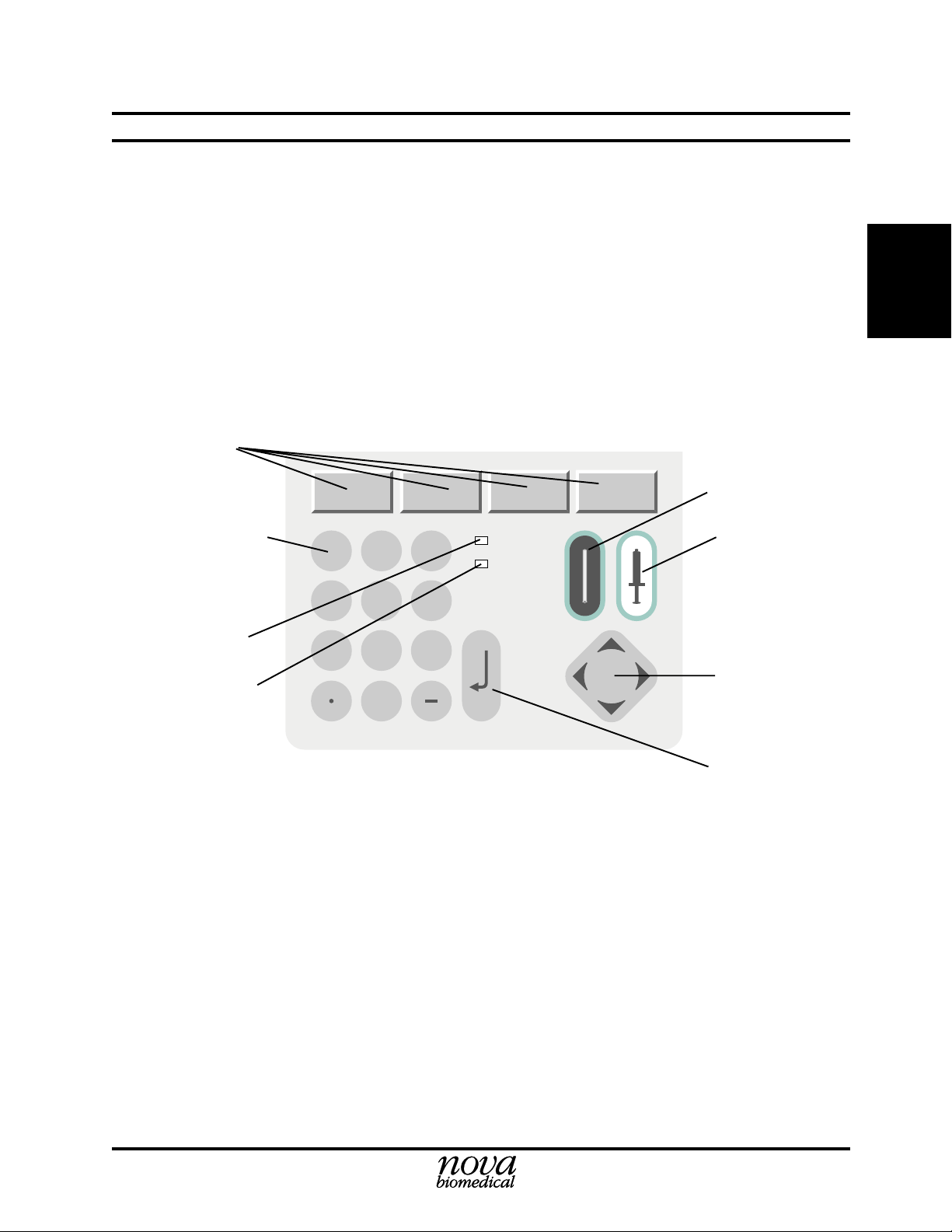
Keypad The keypad allows you to enter information into memory. It consists of 12
number keys (including a decimal point key and a dash key), up (↑), down
(↓), left (←), and right (→) arrow keys, and an ENTER (↵) key. The arrow
keys move the cursor on the display. Also, the left arrow key can be used as
a backspace when entering numerical information. The ENTER (↵) key
places data on the display into memory.
2-2
Analyze Keys There are 2 keys to initiate an analysis: one key has an icon of a capillary tube
and the other key has an icon of a syringe. To perform an analysis with a
capillary sample, press the capillary key. To perform an analysis with a
syringe sample, press the syringe key. These 2 keys are only active when the
Home screen or the Result screen are displaying.
Page 23
2.3.1 General Keypad Entry
Entering numbers:
1. In general, press the arrow keys to select a character entry field or option. Then follow
the screen instructions.
2. For numeric ID entry, press a key to add a character, and the cursor moves to the right.
Up to 20 characters are accepted. If editing an entry, press the left arrow (←) to erase
the last character.
3. After data has been entered correctly, press ENTER (
information into memory.
Soft Keys
2 Setup
↵
) as a final step to store the
Analyze Capillary
2. Setup
Number Keys
Green LED
Yellow LED
1
4
7
2
5
8
0
Figure 2-1. Stat Profile pHOx Keypad
3
6
9
ENTER
Analyze Syringe
Up, Down, Left,
Right Keys
Enter Key
2-3
Page 24

Stat Profile pHOx Reference Manual
2.4 Overview of the Displays (User Interface)
The format that allows the operator to change displays, enter data, and perform functions is
generally referred to as the user interface (controlled by software).
Here are some general rules for the user interface:
2. Setup
• To perform any operation, use the screen instructions to guide you.
• To go back to the Ready screen or the menu for a selected section (i.e., QC, Setup,
etc.), press Home.
• To move back to the previous display, press Previous Page (soft key), if applicable.
• Press Cancel (soft key) to terminate the current operation or sequence or to return to
previous display.
• Press Exit (soft key) to return to the previous display.
• Analyzing a sample and performing calculations take precedence over the user
interface. Therefore, you are temporarily locked out of accessing displays that can
interfere with an ongoing sequence or operation.
• A status message indicates an error condition.
2.5 Adapting the Program to Your Clinical Requirements with the Setup Menu
Use the Setup Menu to adapt the analyzer to your requirements.
2-4
Page 25

2.6 Setup Options
The Setup Menu has the following setup options:
• Results Configuration Menu
• Operation Configuration Menu
2 Setup
- Reference and Alert Limits Setup
PCO
pH,
- Electrode Offsets Setup
pH,
PCO
- Results Units Setup
Temperature: °C or °F
Blood Gas: mmHg or kPa
pH/H+: pH or H
Hb: g/dL or mmol/L or g/L
- Results Suppression: Suppress or not suppress
- Remote Review: ON or OFF
- Patient Name: ON or OFF
- Mandatory Patient ID: ON or OFF
- Analysis Configuration
Analysis Transmit Mode Manual/Auto
Transmit Diagnostic Data Off/ON
Analysis Print Mode Manual/Auto
Print Diagnostic Data OFF/ON
CO-Ox Data Merge Accession nbr/Patient ID
Set Analyzer ID Number:
- Calibration Configuration
Set 1 Point Calibration Frequency 30, 45 min.
Set 2 Point Calibration Frequency 2, 4, 6 hr.
Transmit Diagnostic Data OFF/ON
Print Diagnostic Data OFF/ON
Transmit Drift Data OFF/ON
Print Drift Data OFF/ON
- System Configuration
Set Date Format DD/MM/YY, MM/DD/YY, YY/MM/DD
Set Time Mode 24/12 hr. Mode
Date and Time Set
Measured Barometric Pressure 760 mmHg
Corrected Barometric Pressure 0.0 mmHg
Set Default Hb Used in Calculations: 14.3 g/dL
Set Tone Frequency (100-500Hz): 3500 Hz
- Analysis Mode: A or B
- Hb Type: Measured or Calculated
- STAT Mode: ON or OFF
, PO2, SO2%, Hct, Hb
2
, PO2, SO2%, Hct, Hb
2
+
2. Setup
2-5
Page 26

Stat Profile pHOx Reference Manual
• Communications Menu
- Baud (4800, 9600, 19200)
- Data Bits (7, 8)
- Stop (1,2)
- Parity (None, Even, Odd)
- External Keyboard: Yes or No
- Co-oximeter attached: Yes or No
2. Setup
2.6.1 Password
• Printer Installed or Not Installed
• Passwords: System or Operator
• Operator Passwords: ON or OFF
• Language: English, Chinese, French, German, Italian, Japanese, and Spanish
The first option you should call up is Set Password: either System or Operator.
The System Password, which safeguards the setup parameters, is required to enter the Setup
Menu. Set up System Passwords as follows:
1. Press Menu on the Ready screen to display the Operational Menu screen.
2. Press Setup to display the Setup Menu screen.
3. A pop-up Password screen appears. Enter the default password, 0. This is the
password until one is officially entered.
4. Scroll down with the arrow keys to the Password option and press Enter. A pop-up
screen appears: select System Password.
5 Key in a password number between 1 and 9999 (up to 4 numeric characters) then
press ENTER.
6. Proceed to the next setup option or return to the Operational Menu.
2-6
The Operator Passwords allows you the ability to enable and to enter 200 unique passwords
with privilege levels. When enabled, password entry will be required whenever any of the
home screen soft keys, syringe key, or capillary key are pressed. Entry into any one of the
protected areas depends on the privilege level assigned to the operator of the analyzer.
There are 3 privilege levels: Privilege Level 1 is the most privileged operator and Privilege
level 3 is the default level.
• Privilege Level 1 operators have access to all areas of the analyzer except those
protected by the existing System Password. Level 1 operators do not require PDM
review and may override this feature. Level 1 operators can override QC lockout.
• Privilege Level 2 operators have access to all areas of the analyzer except those
protected by the existing System Password. Level 2 operators will require PDM
review, but may override this feature. Level 2 operators cannot override QC lockout.
• Privilege Level 3 operators have access to analysis only. Level 3 operators will
require PDM review before the results are released. Level 3 operators cannot override
QC lockout.
Page 27

Set up Operator Passwords as follows:
1. Press Menu on the Ready screen to display the Operational Menu screen.
2. Press Setup to display the Setup Menu screen.
3. A pop-up Password screen appears. Enter the default password, 0. This is the
password until one is officially entered.
3. Scroll down with the arrow keys to the Password option and press Enter. A pop-up
screen appears: select Operator Password.
4. Key in a password number, up to 4 numeric characters, and press ENTER.
5. To enable Operator Passwords, scroll down to Operator Passwords then press the
Enter key: Off will turn to On.
6. Proceed to the next setup option or return to the Operational Menu.
2.6.2 Results Configuration Menu
The Results Configuration Menu screen allows you to set reference and alert limits (Low and
High) for all analytes; to adjust electrode offsets for slope and intercept for all analytes; to select
units for temperature, pH, blood gas, and hemoglobin; to turn Remote Review On or Off
(operator Password is enabled when On); Mandatory Patient ID (On or Off); Patient Name (On
or Off); Global Suppression (Test Results).
2 Setup
2. Setup
2.6.2.1 Remote Review
The operator passwords are enabled whenever Remote Review is enabled. To enable Remote
Review (password required), go to the Results Configuration screen, select Remote Review,
then press the Enter key to enable (On) - disable is Off.
Features of Remote Review are as follows:
• Send Results Data to PDM for Review: When all results and calculated parameters are
available, the pHOx Analyzer transmits all this data to the PDM. The analysis cycle
is suspended indefinitely until the PDM returns record or the review is bypassed or
cancelled.
• Suppress Results Data: The PDM will return a reviewed data record to the pHOx
Analyzer. The analyzer will suppress test results based on the information received
from PDM.
• Bypass Review: A pHOx operator with password level 1 or level 2 can bypass a remote
review session. When the session is bypassed, the results are saved, displayed, and
printed (if automatic printing is on). A reviewed data record sent by PDM is ignored
if the review session is bypassed.
2-7
Page 28

Stat Profile pHOx Reference Manual
• Cancel Review: A pHOx operator can cancel a remote review session. When the session
is cancelled, the results are saved, but the results will not be displayed or printed. A
reviewed data record sent by PDM is ignored if the review session is cancelled.
• Review Patient Name: PDM can return a patient name with the suppressed test results.
The patient name will be displayed and printed with the result data if the patient name
entry feature is ON.
• Review Accession Number: PDM can return an accession number with the suppressed
2. Setup
2.6.2.2 Results Suppression
In the Results Configuration screen, test results can be suppressed: will not be displayed,
printed, or transmitted. The suppressed results will only affect analysis results: it will still
calibrate.
Measured tests that depend on the results from a suppressed test will not be displayed. A
dependency error is displayed.
Calculated parameters that depend on suppressed results are not calculated.
Suppress results as follows:
test results. The accession number will overwrite the existing accession number. The
accession number will be displayed and printed with the result data.
1. In the Results Configuration screen, scroll down to Results Suppression.
2. Press the Enter key to get a pop-up screen of the tests.
3. Scroll to the test that you want to suppress then press the Enter key.
4. Scroll to the next test or exit from screen.
5. On the Home screen, the suppressed test will have a strike through the test;
no results will be reported on this test.
2.6.2.3 Mandatory Patient ID
In the Results Configuration screen, the Mandatory Patient ID is enabled or disabled. If
enabled, the Sample Information screen will prompt for Patient ID before the sample analysis
can continue.
A patient ID can be sent from PDM as part of a remote review session.
A patient ID can also be received from a bar code device or external keyboard through the bar
code port.
2-8
Page 29

2.6.3 Operation Configuration Menu
The Operation Configuration Menu screen allows you to setup the analysis output options, to
configure calibration frequency, and to set date, time, barometric pressure, analyzer ID
number, and to change the analysis mode (A or B); to select Hb Measured or Calculated; to
select STAT Mode.
2.6.4 Communications
The Communication screen allows you to setup the communication ports: Baud, Stop, Data, and
Parity. Also, the External Keyboard and CO-Oximeter attached (Yes or No) is selected here.
2.7 QC Setup
2 Setup
2. Setup
To access the QC Setup screen, press QC (soft key) on the Ready screen. Then use the down
arrow key to select QC Setup and press the ENTER key to display the QC Setup screen.
For External Controls, enter the Lot Number, the Expiration Date, the Daily Analysis Times
(up to 3 times per control per day), and the Ranges of each control.
For Internal Controls, the Lot Number, the Expiration Date, and the Control Ranges are
automatically read from the control pack when the QC Auto Cartridge is installed. The Daily
Analysis Times (up to 3 times per control per day) must be manually entered.
2.7.1 QC Lockout
QC Lockout can be enabled (ON) in one of 2 modes or disabled (OFF) from the QC Setup
screen (a password protected screen). When QC Lockout is selected from this screen, a popup screen appears. Lockout OFF, Mode A, and Mode B are the choices. When QC Lockout is
ON (Mode A or Mode B) and QC is due, all test that are scheduled for QC will be lock out. A
QC analysis must be done for a locked out test before an analysis can be performed.
Channel Lockout
A channel will be locked out when it does not pass a QC level. The channel appears with a
strike-through it. This channel will not report results unless a password overrides it. When all
channels become locked out, the analyzer displays the Not Ready screen.
NOTE:
track (Mode A) of the channels that would be locked out if the QC Lockout
feature was ON. If the QC Lockout feature is now turned ON, all those
channels will now become locked out.
If the QC Lockout feature is OFF, the analyzer will internally keep
2-9
Page 30

Stat Profile pHOx Reference Manual
Level Lockout
QC level lockout is enforced for both Mode A and Mode B. If a QC level is not run and QC
Lockout is enabled, all channels in that QC level will become locked out. These channels
remain locked out until the QC analysis cycle of that level is run. A message is displayed on
the Ready/Not Ready screen that a QC analysis is due for a particular level.
2. Setup
NOTE:
track of all channels in this level that would be locked out if the QC Lockout
feature was ON. If the QC Lockout feature is now turned ON, all those
channels will now become locked out.
QC Lockout is activated by selecting either Mode A or Mode B.
Mode A QC lockout locks or unlocks channels based on the last QC level run. A lockout
channel is displayed with a strike-through the channel name. Results for a locked out channel
are not calculated. If more than one QC level is run for the QC cycle, only the last QC level
that a channel is in determines whether the channel will be locked or unlocked. If 3 levels were
run and the channel passed the first 2 levels but failed the last, the channel will be locked out.
To be unlocked, this channel must pass that last level: passing the first 2 does not count. If the
reverse happened and the channel failed the first 2 levels but passed only the last level, the
channel will not be locked out.
Mode B QC lockout locks or unlocks channels based on the last QC run for all levels. A
lockout channel is displayed with a strike-through the channel name. Results for a locked out
channel are not calculated. If a channel fails any level run in a QC cycle, the channel will be
locked. To be unlocked, the channel must pass all levels that it failed.
If the QC Lockout feature is OFF, the analyzer will internally keep
2-10
QC Lockout OFF
When the QC lockout mode is set to OFF, the analyzer internally tracks the lockout state for
each channel. The tracking uses the Mode A lockout. If QC lockout is enabled by selecting
either Mode A or Mode B, any number of the tracked channel can now become locked out.
QC Lockout is password protected, and a password override (Level 1 operators only) is
provided with a pop-up screen. Analysis can be initiated for all channels in a lockout state, but
results will be displayed with the message "Scheduled QC Not Run" and printed with this error
message.
For Automatic QC mode to perform, turn Automatic QC Analysis ON in the Quality Control
screen.
Messages displayed on the Ready/Not Ready screen detail the reason for the QC lockout. These
message are only displayed if QC lockout is enabled (Mode A or Mode B). The following are
the messages and their meanings.
Page 31

2 Setup
Level Lockout Ready/Not Ready Screen Messages
Internal L(n) Not Run Internal L(n) missed a scheduled QC cycle. All channels are locked
out for that level. Results for the locked out channels will not be
reported. Internal QC level (n) must be run to unlock the channels.
External L(n) Not Run External L(n) missed a scheduled QC cycle. All channels are locked
out for that level. Results for the locked out channels will not be
reported. External QC level (n) must be run to unlock the channels.
Mode A Ready/Not Ready Screen Messages
QC Lockout All channels are locked out. Analysis cannot be run without a
password override. Any QC level that is run will unlock the
channels.
Mode B Ready/Not Ready Screen Messages
QC Lockout Internal L(n) Internal L(n) has channels that are locked out. Results for locked out
channels will not be reported. Internal QC level (n) must be run to
unlock the channels.
QC Lockout External L(n) External L(n) has channels that are locked out. Results for locked
out channels will not be reported. External QC level (n) must be run
to unlock the channels.
2. Setup
2.8 Remote Control
Remote control is enabled on the PDM side. See the PDM Manual for information. The
analyzer's system ready status information is sent to the PDM upon each change of status:
barometer, temperature, reagent pack, control pack, minimum calibration, QC test lockout, QC
level lockout, and standby mode state.
The system test status information is sent to the PDM after calibration and QC are completed.
This test status information includes the calibration status and QC lockout status of each test
and the performance status of glucose.
Remote control from the PDM can do the following:
• Initiate a 2-point calibration sequence
• Run an internal QC (any level)
• Turn global suppression on or off
• Enter or delete passwords
• Maintain a maintenance activity record that is sent to the PDM at the completion of
the maintenance. The maintenance status information includes an operator ID, an
activity ID, and the date and time of the maintenance.
2-11
Page 32

Stat Profile pHOx Reference Manual
2. Setup
2-12
Page 33

3 Operation
The Stat Profile pHOx Analyzer is pictured below with its components.
1
4
7
8
0
3 Operation
3
3. Operation
1
2
3
5
2
6
9
4
5
Figure 3.1 Nova Stat Profile pHOx Components
1. Display
2. Keypad
3. Printer
4. Sampler
5. Door/Front Panel
DWG #10-1016A
3-1
Page 34

Stat Profile pHOx Reference Manual
11
1
2
3
4
3. Operation
5
10
9
8
7
DWG #10-1017A
3-2
Figure 3.2 Analytical Compartment
1. Waste Line
2. Reference Line
3. Pinch Valve (Reference)
4. Pump and Pump Tubing
5. Reagent Pack Opening
6
6. Control Pack Opening
7. Sampler
8. Air Detector
9. Sensor Module With Sensors
10. Reference Electrode
11. Pinch Valve (Waste)
Page 35

3.1 Display and Door
The display is a liquid crystal display (LCD). To adjust the display intensity, use the right
(darker) or left (lighter) arrow key while displaying the Ready or Not Ready screen. Prompts,
menus, status information, error messages, patient results, etc. are displayed on the screen. The
default language is English. (Other languages can be selected through the setup menu.)
The door may be opened to access the analytical compartment of the system. There is an inside
latch that is easily released when you pull at the bottom right side of the door.
3.2 Keypad
The primary input device is the keypad. It has the digits (0 thru 9), a decimal point, a dash, an
ENTER key, arrow keys (up, down, left, and right), and analyze keys (syringe and capillary
icons). There are also 4 Soft Keys whose function is determined by the legend displayed just
above it on the LCD display: Print, Exit, Cancel, Menu, etc.
3 Operation
3. Operation
3.3 Printer (Optional)
The internal printer (optional) will be able to print patient results, list the analyzer's setup
information, error log, etc.
3.4 Sampler
The sampler allows for the aspiration of the sample. The sampler has 2 sampling positions:
horizontal for the aspiration of a sample from a capillary tube and inclined for the aspiration
of the sample from a syringe. No special adapters are required to aspirate a sample from a
capillary tube. The capillary or syringe positions are selected by pressing the Black Capillary
key or the White Syringe key.
3-3
Page 36

Stat Profile pHOx Reference Manual
3.5 Sensor Module
The sensor module includes the preheater and flow cell. The preheater heats samples and
controls to 37°C. In addition, it contains the hematocrit impedance electrode and 2 air detectors.
The sensor module geometry is an interlaced configuration with the reference electrode at the
top of the sensor module, 3 sensors on the left side, 2 sensors on the right side. In addition to
the Hct sensor located in the preheater, there are 6 sensors: Reference electrode, Na+, PCO2,
SO
(optic), pH, and PO2. A window in the door allows flow path visibility and is augmented
2
by a backlight.
3.6 Sensors
3. Operation
The Sensors housed in the sensor module are the core of the Stat Profile pHOx Analyzer. The
methodology used by each sensor are
Electrode Methodology
+
Na
pH Hydrogen ion-selective glass electrode
PCO
2
PO
2
Hct Impedance electrode
Hb Impedance electrode/photometry
SO
2
The sensors clip into the sensor module, and electrical contact is automatically made.
3.7 Reference Electrode
The Reference Electrode is mounted above the sensor module. It is a solid-state Ag/AgCl
electrode and provides the reference voltage for comparison to sample voltages. The exit port
of the flow path is located on this electrode.
Sodium ion-selective electrode
Severinghaus-type electrode
Polarographic Clark-type electrode
Reflectance photometry (fiber optics)
3-4
Page 37

3.8 Barometric Pressure Module
The Barometric Pressure Module, located on a printed circuit board, continuously monitors the
barometric pressure. This barometer can be calibrated against an external barometer, if desired,
through the software.
3 Operation
3.9 Pinch Valves
There are 2 pinch valves: one is used to control the flow of the reference fluid and the other one
is used to control the flow of fluids through the sensor module.
3.10 Peristaltic Pump
The pump is a 6-roller peristaltic pump driven by a stepper motor.
3.11 Reagent Pack
The reagent pack contains 6 flexible bags in a cardboard carton. One of these is a waste bag
to collect the used reagents, controls, and samples. The other 5 bags contain standard reagents:
A, B, C, D, and R. Each bag includes a fitment with a septa.
The exposed bag fitments are arranged in a line along the rear of the pack. The septa are pierced
during insertion of the pack. The lot number and expiration date are printed on the front of the
pack.
The Reagent Management System (RMS) of the reagent pack automatically enters the
calibration values, the lot number, the fluid volumes, and the expiration date to the analyzer's
computer after insertion of the reagent pack.
3. Operation
3-5
Page 38

Stat Profile pHOx Reference Manual
3.12 Auto-Cartridge QC
Nova Biomedical's Auto-Cartridge QC is a total automated control system contained within
a single on-board reagent cartridge. This system allows any level of quality control to be run
at any time: either on a programmed schedule or on demand. The Auto-Cartridge QC system
reduces costs by eliminating the time and labor required to manually perform quality control.
Each Nova Auto-Cartridge contains 3 levels of blood gas controls, 2 levels of hematocrit,
SO
%, and hemoglobin controls, plus software that automates running controls and storing
2
quality control data. When the cartridge is installed, all quality control target ranges, lot code,
and expiration date information is automatically downloaded to the analyzer. The user then
programs the pHOx Analyzer to automatically analyze up to 3 quality control levels, 3 times
3. Operation
per day (a total of 9 analyses per day). If any analyte is outside the target range, it is
automatically reanalyzed. If a control value remains out of range, the user is notified.
All quality control data is automatically stored. Daily and cumulative statistical reports and
Levey-Jennings graphs can be printed at any time. This automation assures that quality control
is always performed accurately and on schedule, thereby guaranteeing regulatory compliance.-
3.13 Movement Of Fluids
To begin an analysis, press the Capillary or Syringe key to move the sampler to either the
capillary or syringe position. Present the sample to the probe and press either Aspirate Normal
or Aspirate Micro (soft keys). The Aspirate Normal soft key allows for the aspiration of 70 µL
of sample, and the Aspirate Micro soft key allows for the aspiration of 45 µL of sample. The
sample is aspirated by the peristaltic pump until the leading edge is detected by either the 45 µL
or 70 µL air detector. After the aspiration is completed, there is an audible beep and a pop-up
display that prompts you to press Analyze after removing the syringe or capillary. The sample
is advanced until the leading edge is properly located in front of the electrodes. Once all
measurements have been completed, the sample is pumped to the waste and the flow path is
washed.
3-6
Update to PN 22363 Rev. D 3/2002
Page 39

3.14 Operational Overview
The Stat Profile pHOx Analyzer is a stand-alone, microprocessor-based instrument for
analyzing blood samples. The analyzer measures pH, PCO2, PO2, SO2%, Hct, and Hb in
heparinized blood. The analyzer additionally calculates the parameters listed in Section 1.2.
The software allows the control of the following functions:
3 Operation
• Calibration
• Sample analysis
• Quality Control
• Diagnostic and maintenance functions
• System configurations
• Communication interface with external devices
• Storage and retrieval of patient records
After the analyzer is set up and calibrated, it is ready to begin analyzing samples. Samples can
be aspirated from syringes, capillaries, open tubes, small sample cups, or ampules. After
sample acceptance, patient data can be entered. A limited number of patient records (18) is
stored in a "circular" buffer. Once the buffer is full, each new saved record overwrites the oldest
record.
3.15 Ready to Analyze
When the Ready to Analyze screen is displayed, the analyzer is ready to run samples.
The following information is displayed on the screen:
3. Operation
• All calibrated analytes - Uncalibrated analytes are X'd out.
• Next QC time (if selected in Setup)
• Next Calibration time
• Amount remaining for reagents (A bar graph is displayed for fluid volumes greater
than 10% of the original volume.)
• Soft keys
- Results - Patient
- QC - Run Quality Control Samples
- Calibrate
- Menu (Operational)
3-7
Page 40

Stat Profile pHOx Reference Manual
3.16 Calibrating the Analyzer
The analyzer uses a 2-point calibration to measure pH, PCO2, PO2, Hct, Na+ electrode slopes
and to verify electrode performance. This 2-point calibration occurs automatically at regular
intervals, or, if desired, calibration can be manually initiated. The options are listed in the
Calibration screen. If an electrode fails to calibrate for any reason, an appropriate error code
is generated. An operator can cancel a calibration in progress from the keypad to run a stat
analysis. If this is done, the previous calibration slopes are used for the analysis calculations.
3.16.1Two-Point Calibration (Automatic and Manual)
3. Operation
The analyzer performs an automatic 2-point calibration at 2, 4 or 6 hour intervals (as selected
in Setup). These Auto-Cal intervals can be extended as follows:
Auto-Cal Extension: System Busy when Auto-Cal scheduled to run
If the system is busy when an Auto-Cal is scheduled to run, the request is held in a queue until
the current sequence is completed. The system presents the operator with a pop-up that allows
the delay of a 2-point calibration sequence for an additional 10 minutes. The 2-point calibration
sequence may be delayed indefinitely.
3.16.2Manual Calibration
Manual calibrations may be initiated to calibrate any uncalibrated electrodes or calibrate the
system after maintenance. Press the soft key for Calibrate on the Home screen. The 2-point
Calibration screen is displayed with options for calibration. Use the arrow keys to go to the
desired option. Then press ENTER.
3.16.3SO2/Hb Calibration
O2 and Hb must be manually calibrated with 2 external calibrators. To calibrate SO2 and Hb,
S
press Calibrate on the Home screen. Then go to option 2 and press Enter. Follow the directions
on the screen. You will be asked to enter the assay values for each level of calibrator. These
2 values can be verified on the SO2 Sensor Subsystem screen.
3-8
Page 41

3.16.4One-Point Calibration
All analytes are checked for calibration every 30 or 45 minutes if analysis Mode A was selected in
the setup options. This check is done by exposing the electrodes to a known standard and comparing
the new value to the value obtained during the 2-point calibration. A calibration drift error is generated
if the difference exceeds the internally set limits. The flagged sensor will revert to an uncalibrated state.
3 Operation
3.17 Quality Control
The Quality Control screen is accessed from the Home screen by pressing QC (soft key). Times
for running QC can be set through the QC Setup. This menu also allows access to reports and
manipulation of daily, monthly, cumulative data, and Levy Jennings graphs.
Definitions:
Daily Statistics - All QC samples stored since the last Move Daily Data to Month-to-Date was
performed. Daily data accumulation begins at midnight of the current day.
Monthly Statistics - Cumulative statistics for the last 32 days. Monthly statistics are simply
cumulative statistics.
Cumulative Statistics - A running accumulation of mean, SD (standard deviation), and CV%
(coefficient of variance in percent) for all stored QC samples. Although these statistics are
based on the total number of samples, the n on the screen and on the printout indicates the
number of days. The Cumulative Statistics cannot be reset except by changing to a control with
a new lot number.
NOTE:
30 or 45 minutes, instead the 1-point calibration is automatically performed
with each sample analysis..
If Mode B is selected, a 1-point calibration does not take place every
3. Operation
NOTE:
that analyte, the SD result for that analyte is not displayed (blank screen).
When a new Auto-Cartridge QC with a new lot number is installed, the data from the previous
lot number is erased from the memory of the analyzer. Thus, you are unable to run lots in
parallel to validate the new lot to the old by alternating packs on the same unit.
Nova Recommendation: All Nova controls ship with a product insert sheet. This product insert sheet
contains the target value ranges for each level of QC contained in the pack. Nova’s recommendation for conversion to a new lot number is to use the product insert sheet range levels for the
first 30 days or until sufficient data is collected to establish the new target values. After sufficient
data is collected, the established values and ranges can be entered into the analyzer.
Alternate Method: If this method is inadequate, Nova recommends the use of the external
controls run in parallel and overlapping with the on-board product change over. This method
offers continuity in monitoring performance during the change over period, but it does add
cost. The external QC monitoring can be done using the QC program on the analyzer.
When the SD approaches zero and is smaller than the display range of
3-9
Page 42

Stat Profile pHOx Reference Manual
3.17.1Running QC Samples
From the Home screen, press QC (soft key) to display the Quality Control (QC) screen. Follow
the instructions on the screen.
3. Operation
NOTE:
entered) and you choose to delay or not run the QC, a message is displayed
indicating that QC was not run. If the QC lockout mode is selected and a
scheduled QC is not allowed to run, the analyzer becomes Not Ready.
If you power up without QC scheduled and QC Lockout off, the analyzer
will boot up in control.
NOTE:
Setup QC Levels screens, then turn Automatic QC Analysis ON in the
Quality Control (QC) screen.
If the mandatory QC mode is selected (i.e., QC times have been
To use the Auto QC mode, set the times for the 3 control levels in the
3.17.2Running Linearity Solutions/Proficiency Samples
From the Home screen, press QC (soft key) to display the Quality Control (QC) screen. Then
select Proficiency. Follow the instructions on the screen.
NOTE:
When a sample is run in this mode, slopes and offsets do not apply.
3.18 Analyzing Samples
Samples can be analyzed from capillaries of various sizes and glass or plastic syringes from
1 cc to 10 cc. Samples are aspirated from a horizontal position for capillary tubes through a
built-in adapter or at a 30° angle from the horizontal for syringes and ampule control samples.
1. Once the Capillary or Syringe button is pressed, the Aspirate screen is displayed.
2. Press one of the soft keys: Aspirate Micro or Aspirate Normal.
3. Then press Aspirate (soft key). The Sample Information screen is displayed.
4. The Sample Information screen is 2 screens. Screen 1 has Accession number, Patient
ID number, Patient Temperature, Combine CO-Ox Data (yes/No), Operator ID, and
Patient Name.
Screen 2 has Sample Type (Arterial, etc.), Puncture Site (Radial Artery, Brachial
Artery, Femoral Artery, Arterial Catheter, or Unspecified), Ventilator Rate/Min,
Tidal Volume, PEEP/CPAP, and Mode of Therapy (Unspecified, CMV, ACV,
SMV, PEEP, CPAP, PSV, PCV).
5. Press View Results (soft key) to display the Results - Measure screen. To view all
results (measured and calculated), continually press Next Page (soft key).
3-10
Page 43

3.18.1 Analyzing from a Syringe or an Ampule
From the Home screen (Ready for Analysis), press the syringe key (for syringe or ampule
samples) to position the probe. To aspirate the sample, press Aspirate Normal (soft key).
Follow the directions on the screen.
3 Operation
NOTE:
To run in micromode, press Aspirate Micro (soft key). The time is
typically longer than normal mode. For other functions, follow the screen
instructions.
Syringe
#10-1024A
G
DW
Figure 3.3 Analyzing from a Syringe
3. Operation
3-11
Page 44

Stat Profile pHOx Reference Manual
3.18.2Analyzing from a Capillary Tube
From the Home screen (Ready for Analysis), press the Capillary key to position the probe. To
aspirate the sample, press Aspirate Normal (soft key). Follow the directions on the screen.
3. Operation
NOTE:
typically longer than normal mode. For other functions, follow the screen
instructions.
Capillary Tube
To run in micromode, press Aspirate Micro (soft key). The time is
G #10-1070A
DW
Figure 3.4 Analyzing from a Capillary Tube
3-12
Page 45

3.18.3Analyzing in AV Shunt Mode
The AV Shunt sample analysis combines both the pHOx and the CO-Oximeter results for 2
sample types: mixed venous and arterial. The mixed venous is analyzed first on the pHOx, then
the same sample is analyzed on the CO-Oximeter. Next the arterial is analyzed: first on the
pHOx then on the CO-Oximeter. Follow this procedure with the aid of the pHOx screen
prompts:
1. From the Home screen (Ready for Analysis), press the Syringe key to position the
probe.
2. Press AV Shunt (soft key).
3. Position the mixed venous sample and press Aspirate (soft key).
4. Remove the sample and press Analyze (soft key).
5. Run the same venous mixed sample on the CO-Oximeter.
6. When message, Mixed Venous sample complete, is displayed, analyze the arterial
sample. Position arterial sample and press Aspirate (soft key).
7. After aspiration, remove sample and press Analyze (soft key).
8. Run the same arterial sample on the CO-Oximeter.
9. Press Results (soft key) to get all the results including the combined results.
3 Operation
3. Operation
3.18.4Stat Mode
Stat Mode is turned ON or OFF in the Operation Configuration Menu screen. When Stat Mode
is ON, the Sample Information screen is not displayed each time an analysis is initiated.
3-13
Page 46

Stat Profile pHOx Reference Manual
3.19 Results Recall
Previously analyzed samples can be recalled for viewing only. These records are stored in a
circular buffer. When the buffer becomes full (greater than 18 analyses), the oldest record in
the buffer is overwritten. The record is automatically saved by the analyzer when the analysis
is successfully completed. The results are cataloged by date, time, accession number, and ID
number. These results are accessed through the Ready screen.
3. Operation
NOTE:
results, follow the results recall steps, then when the results are on the
screen press the decimal (.) key, then the Print (soft Key). The results should
then retransmit.
NOTE:
1. From the Ready screen, press Results (soft key).
2. Use the arrow keys to select the desired results. (Or press Latest Results (soft key)
to view the last sample analyzed.)
3. Press ENTER to view the selected results.
4. Follow directions on the screen.
When connected to a computer and you want to retransmit the
Proficiency results are not stored.
3-14
Page 47

4 Operating Procedures
The following sections provide detailed information and directions to operate the Stat Profile
pHOx Analyzer at peak efficiency. From the Home screen, press Menu (soft key).
From the Operational Menu screen, the following options can be performed:
• Set Sample Number Counter
• Change the Reagent Pack
• Change the Control Pack
• Flowpath/Probe maintenance: change tubing, sensors, purge, etc.
• Flowpath Cleaning
• Sensor Conditioning
• Standby Mode
WARNING: Blood samples and blood products are potential sources of hepatitis and
other infectious agents. Handle all blood products and flow path components (wasteline, probe, sensor module, etc.) with care. Gloves and protective clothing are
recommended.
4 Operating Procedures
4. Op. Proc.
A Maintenance Log that includes performance records and a maintenance checklist is supplied
with your instrument. Use this log to record data for long-term performance verification and
to document maintenance.
4.1 Sample Number Counter
The screen allows you to check and/or to change the Sample Number Counter, but the Total
Samples Accepted number, the Total Internal QC Samples Accepted number, and the Total
Samples and Internal QC number are read only.
4.2 Scheduled Maintenance
It is important to perform preventive maintenance as scheduled. The Maintenance Log
(PN 22362) gives suggested schedules based on sample volume. Space is provided for
slopes and control results in the Maintenance Log.
4-1
Page 48

Stat Profile pHOx Reference Manual
DWG #10-1003A
4.2.1 Reagent Pack and Control Pack Changing
The reagent pack and/or control pack should be changed when the system indicates the pack
is empty. From the Operation Menu screen, select Change Reagent Pack or Change Control
Pack and press Enter. Mix the pack thoroughly by inverting several times. Then follow the directions
on the screen to replace the packs and the capillary adapter.
4. Op. Proc.
WARNING:
When the reagent pack or control pack is removed, keep your
fingers and hands away from the back of the pack compartment. There are
sharp needles that can cause injury, and the waste needle is also a biohazard.
NOTE:
The reagent or the control pack must be replaced through the
Operation Menu screens. If you remove and replace a pack (even if it is the
same pack) outside these screens, you will not be able to prime the analyzer, and you will not be able to calibrate or to analyze samples (Reagent
Pack) or to analyze internal controls (Control Pack). If you have removed
and replaced a pack outside these screens, go to the appropriate screen and
press Prime (soft key).
NOTE:
The capillary
adapter comes in the
reagent pack box. As you
put on the new adapter,
make sure the probe goes
through the center hole of
the adapter.
4-2
Control Pack
Reagent Pack
Figure 4.1 Replacing the Reagent Pack and the Control Pack
Page 49

4.2.2 Flowpath/Probe Maintenance
The Flowpath/Probe Maintenance option removes fluid from the flow path, so that tubing,
sensor, or probe changes, or other maintenance can be performed without fluids leaking or
pumping into the analyzer. After all replacements are made, press Continue (soft key) to prime
the flow path. The analyzer will prime and give you the option to calibrate now or later.
4.2.3 Standby Mode
This option allows you to place the analyzer into a standby mode and allows you to reactivate
the analyzer out of the mode at a programmed time and date. The standby mode will use less
reagents and controls because the analyzer will not run its automatic calibration cycles.
Calibration is lost except for SO2 and Hb. Standby mode ends after the set time is elapsed; if
you turn Standby off; or if you initiate a calibration. The analyzer automatically performs 2
calibrations or a second calibration after Standby mode ends.
The following is the procedure to set the Standby Mode:
1. From the Operational Menu, scroll down to the Standby Mode with the Down
Arrow key.
2. Press ENTER (once if OFF or twice if ON).
3. To set the date, press ENTER again - the date becomes blank.
4. Key in the date that you want the analyzer to come out of Standby Mode.
5. Press ENTER to set (DO NOT press OK).
6. Press any Arrow key to change the time. Then press ENTER - the time becomes blank.
7. Key in the time that you want the analyzer to come out of Standby Mode.
8. Press ENTER to set (DO NOT press OK).
9a. Press OK (soft key) to go into Standby Mode. Another pop-up screen appears to
verify that you want to go into Standby Mode. Press OK (soft key) again. Standby
Mode is now ON.
9b. Press Cancel (soft key) to cancel Standby Mode. The date and time reverts to the
previous settings. The Standby Mode is now OFF.
4 Operating Procedures
4. Op. Proc.
4.2.4 pH and Sodium Sensors Replacement
1. From the Operation Menu screen, select Flowpath/Probe Maintenance and press
Enter.
2. Open the door and locate the pH or sodium sensor.
3. Remove the sensor from the sensor module by pinching the front and rear of the
sensor clip.
4. Clean the sensor module cuvette with a cotton swab.
5. Insert the new sensor into the sensor module by sliding the sensor body into the
sensor module until the sensor clips into place.
6. Press the Continue key (soft key).
7. A message displays, Priming Flow Path. Please wait until the time bar completes.
8. Recalibrate.
4-3
Page 50

Stat Profile pHOx Reference Manual
4.2.5PCO2 Sensor or Membrane Replacement
The following procedure explains how to replace the PCO2 sensor and membrane.
1. From the Operation Menu screen, select Flowpath/Probe Maintenance and press
Enter.
2. Open the door.
PCO
3. Locate the
4. Remove the
sliding it out of the sensor module. Be careful not to touch the electrical contacts.
5. Unscrew the used membrane cap from the sensor body and discard it.
sensor.
2
PCO
sensor by pinching the front and rear of the sensor clip and
2
4. Op. Proc.
NOTE:
If installing a new sensor,
carefully remove the shipping cap
before installing a new membrane
cap. Do not touch the electrical
DWG #10-1066A
contacts of the sensor.
6. Take a new PCO2 Membrane Cap
(PN 25048) that is prefilled with internal
filling solution. Hold the shipping plug end
of the membrane cap and shake it gently, as
if shaking down a thermometer, to ensure
that the air bubble is at the threaded end of
the membrane cap.
Figure 4.2 Shaking Down Membrane Cap
7. Unscrew the black shipping plug from the cap. Screw the cap onto the sensor.
Discard the black shipping plug. Do not tilt the membrane cap when installing onto
the sensor; the internal filling solution may drip out.
Shipping Plug
123456
See air gap
after shaking
Sensor
Internal filling solution
4-4
DWG #10-1067A
Vent Hole
Vent Cover
Figure 4.3 The PCO2 Membrane Cap (With Shipping Plug and Attached to Sensor)
DWG #10-1068A
Page 51

4 Operating Procedures
NOTE:
The prefilled PCO2 cap does not require any additional filling
solution. Do not add or remove any Internal Filling Solution. The prefilled
level of solution is all that is needed to operate the analyzer successfully.
Adding or subtracting from the
prefilled level will effect the sensor's
performance.
8. Degas the sensor as follows:
Sensor
Body
Vent Hole
a. Hold the sensor with the cap down-
ward. With a wrist-snapping motion,
shake the sensor down to move air
Vent Cover
bubbles to the back of the sensor.
b. With the sensor tip still downward,
observe the tip for bubbles. If bubbles are present, tap the sensor with a
finger to loosen the bubbles and again shake the sensor down. Repeat if
necessary.
9. Wipe the sensor body and cap dry. Remove a single vent cover from the blue
backing and place over the vent hole (see Figure 4.4). Press firmly to ensure a good
seal.
Figure 4.4 Vent Cover on Membrane Cap
DWG #10-1069A
4. Op. Proc.
10. Clean the sensor module cuvette with a cotton swab.
11. Insert the sensor into the sensor module by sliding the sensor body into the sensor
module until the sensor clips into place.
12. Press the Continue key (soft key).
13. A message displays, Priming Flow Path. Please wait until the time bar completes.
14. Condition the sensor module.
NOTE:
All sensors must be in the sensor module during a Sensor Condition-
ing cycle.
a. Fill a 2 mL sample cup 1/2-full of whole blood.
b. Select Sensor Conditioning from the Operation Menu and press Enter.
c. Immerse the probe in the sample.
d. Press Continue to aspirate the sample. Withdraw the cup after the tone.
e. A message displays, Flow Path conditioning in progress. Please wait until
the time bar completes.
15. Return to the Home screen and calibrate the sensor 2 times.
16. If the sensor does not calibrate due to slope errors, remove air bubbles as follows:
a. Open the door, remove the sensor and shake down the sensor with a wrist-
snapping motion to move air bubbles to the back of the sensor.
b. Reinsert the sensor into the sensor module and close the door.
c. Recalibrate.
4-5
Page 52

Stat Profile pHOx Reference Manual
4.2.6PO2 Sensor Polishing and Membrane Replacement
The following procedure explains how to polish and to replace the PO2 sensor and/or to replace
the membrane cap.
4. Op. Proc.
NOTE:
The PO2 sensor should be polished during routine membrane
replacement or during troubleshooting characterized by either slope and/or
QC recovery problems.
1. From the Operation Menu screen, select Flowpath/Probe Maintenance and press
Enter.
2. Open the door and locate the PO2 sensor.
PO
3. Remove the
Sensor by pinching the front and rear of the sensor clip and sliding
2
it out of the sensor module.
4. Unscrew the used
PO
cap from the PO2 body and dispose of it.
2
5. If polishing the sensor is unnecessary, go to Step 7 to replace the PO2 cap.
6. Polish the sensor as follows:
a. Take a polishing paper from kit PN 21795 and place a couple of drops of
deionized water onto it.
b. Hold the PO2 polishing paper so that the tip of your index finger provides
light pressure against the back of the paper.
c. Gently polish the sensor tip on the paper, move the tip in a circular motion
for about 10 seconds. Discard the polishing paper.
d. Wipe the sensor tip with a lint-free tissue soaked in deionized water.
CAUTION:
Never polish the sensor tip on a hard surface such as a bench top.
4-6
7. Take a new PO2 Premembraned Cap
(PN 21795) that is prefilled with
internal filling solution, and shake it
gently to ensure that the solution is
away from the threaded end and at
the membrane end. Unscrew and discard the shipping plug from the cap.
8. Insert the sensor body straight down
(vertical position only to ensure no
loss of internal filling solution) into
the filled cap and screw the cap onto
the sensor body. (See Figure 4.5.)
NOTE:
The prefilled PO2 cap does not require any additional filling solu-
tion. Do not add or remove any Internal Filling Solution. The prefilled level
of solution is all that is needed to operate the analyzer successfully. Adding
or subtracting from the prefilled level will effect the sensor's performance.
pO2 Sensor
Shipping Plug
See air gap
after shaking
Internal
Filling Solution
Figure 4.5 Installing the PO2 Membrane Cap
DWG #10-1043A
Page 53

4 Operating Procedures
9. Degas the sensor as follows:
a. Hold the sensor with the cap downward. With a wrist-snapping motion,
shake the sensor down to move air bubbles to the back of the sensor.
b. With the sensor tip still downward, observe the tip for bubbles. If bubbles
are present, tap the sensor with a finger to loosen the bubbles and again
shake the sensor down. Repeat if necessary.
10. Dry the sensor with a lint-free tissue. Take care not to touch the tip.
11. Clean the sensor module cuvette with a cotton swab.
12. Insert the sensor into the sensor module by sliding the sensor body into the sensor
module until the sensor clips into place.
13. Close the door and press the Continue key (soft key).
14. A message displays, Priming Flow Path. Please wait until the time bar completes.
15. Condition the sensor module.
NOTE:
All sensors must be in the sensor module during a Sensor Condition-
ing cycle.
a. Fill a 2 mL sample cup 1/2-full of whole blood.
b. Select Sensor Conditioning from the Operation Menu and press Enter.
c. Immerse the probe in the sample.
d. Press Continue to aspirate the sample. Withdraw the cup after the tone.
e. A message displays, Flow Path conditioning in progress. Please wait until
the time bar completes.
16. Return to the Home screen and calibrate the sensor 2 times.
17. If the sensor does not calibrate due to slope errors, remove air bubbles as follows:
a. Open the door, remove the sensor and shake down the sensor with a wrist-
snapping motion to move air bubbles to the back of the sensor.
b. Reinsert the sensor into the sensor module and close the door.
c. Recalibrate.
4.2.7 Reference Electrode Replacement
1. From the Operation Menu screen, select Flowpath/Probe Maintenance and press
Enter.
2. Open the door.
3. Disconnect the W and R-lines from the reference electrode.
4. Pull up the retaining screw.
4. Op. Proc.
4-7
Page 54

Stat Profile pHOx Reference Manual
Retaining Screw
DWG #10-1012A
4. Op. Proc.
W-line
R-line
Figure 4.6 Disconnecting the Reference Electrode
5. Lift the used reference electrode up and out of the way of the sensor module.
6. Place the new Reference Electrode (PN 06025) on top of the sensor module, align
the electrode sides with the backplate sides. Ensure that the reference electrode
connector is seated properly on the sensor module interconnect tubing.
W
R
Reference Electrode
W
R
W
R
DWG #10-1011A
Figure 4.7 Placing New Reference Electrode onto Sensor module
Reference Electrode
7. Push down on the retaining screw.
8. Attach the W/R-lines to the reference electrode and press Continue (soft key).
9. A message displays, Priming Flow Path. Please wait until the time bar completes.
10. Recalibrate.
4-8
Page 55

4.2.8SO2 Sensor Maintenance
1. From the Operation Menu screen, select Flowpath/Probe Maintenance and press
Enter.
2. Open the door and locate the SO2 sensor.
3. To remove the sensor, unscrew the lead screw and pull out.
4. Clean the sensor surface with a lint-free tissue that is soaked with 10% Sodium
Hypochlorite Solution (bleach). Rinse with deionized water and blot dry.
5. Clean the sensor module cuvette with a cotton swab.
6. Reinstall the sensor and tighten the lead screw.
4 Operating Procedures
DW
G #10-1015A
4. Op. Proc.
Figure 4.8 Reinstalling the SO2 Sensor
7. Press Continue (soft key) to prime the flow path.
8. A message displays, Priming Flow Path. Please wait until the time bar completes.
9. From the Home screen, press Calibrate (soft key).
10. Follow the instructions on the screen.
4-9
Page 56

Stat Profile pHOx Reference Manual
0
10
4.2.9 Pump Tubing Replacement
The pump tubing should be replaced at intervals prescribed in the maintenance log. Replace
the tubing that goes around the pump as follows.
1. From the Operation Menu screen, select Flowpath/Probe Maintenance and press
Enter.
2. Open the door.
3. Disconnect the R-line and W-line (the ones that go through the pinch valves) from
the pump manifold.
4. Disconnect the R and W-pump tubing lines from the labeled outlets
that are below the pump manifold.
5. Slide the top and bottom tube manifolds out
6. Discard the used tubing and manifolds.
4. Op. Proc.
7. On the new pump tubing, Locate
the half circle on one of the manifolds. This is the top manifold.
A
7
0
0
-1
0
1
#
G
W
D
Figure 4.9 Pump Tubing
Half circle
8. Slide the top pump tubing manifold
into its slots. The top manifold's half
circle should line up with the half circle
on the slot.
9. Stretch the pump tubing around the
pump and slide the bottom manifold
into its slots.
10. Connect the R-pump tubing line to the
R-labelled outlet below the pump manifold (see Figure 4.10).
11. Connect the W-pump tubing line to the
W-labelled outlet below the pump mani-
R
W
-
DWG #1
fold (see Figure 4.10).
Figure 4.10 Connecting the Pump Tubing W and R-lines
12. Reconnect the R-line and W-line (the ones that go through the pinch valves) to the
pump manifold.
13. Close the door and press the Continue key (soft key).
14. A message displays, Priming Flow Path. Please wait., and a time bar to completion
also appears.
15. Recalibrate.
4-10
Page 57

4.2.9.1Waste Line Replacement
W
W
The waste line should be replaced at intervals prescribed in the maintenance log. The W-line
connects at the middle of the top pump manifold, travels through the waste pinch valve, and
connects to the top W-labelled outlet on the reference electrode. The W-line can be replaced
by following this procedure.
1. From the Operation Menu screen, select Flowpath/Probe Maintenance and press
Enter.
2. Open the door.
3. Disconnect the W-line from the pump manifold, pinch valve, and reference
electrode. Discard the used tubing.
4. Attach the new W-line starting with the pinch valve. At the pinch valve segment
of the W-line (elastic segment), stretch the segment and slide it into the pinch valve.
5. Connect the line to the W-labelled outlet of the reference electrode and the middle
of the top pump manifold. (See Figure 4.11.)
4 Operating Procedures
4. Op. Proc.
Pinch valve
segment
Figure 4.11 Connecting the W-line
6. Close the door and press the Continue key (soft key).
7. A message displays, Priming Flow Path. Please wait., and a time bar to completion
also appears.
8. Recalibrate.
4-11
Page 58

Stat Profile pHOx Reference Manual
4.2.9.2 Reference Line Replacement
The reference line should be replaced at intervals prescribed in the maintenance log. The Rline connects at the outside of the bottom pump manifold, travels through the reference pinch
valve, and connects to the bottom R-labelled outlet on the reference electrode. The R-line can
be replaced by following this procedure.
1. From the Operation Menu screen, select Flowpath/Probe Maintenance and press
Enter.
2. Open the door.
3. Disconnect the R-line from the pump manifold, pinch valve, and reference
electrode. Discard the used tubing.
4. Attach the new R-line starting with the pinch valve. At the pinch valve segment of
the R-line (elastic segment), stretch the segment and slide it into the pinch valve.
5. Connect the line to the R-labelled outlet of the reference electrode and the outside
of the bottom pump manifold. (See Figure 4.12.)
4. Op. Proc.
Pinch valve
segment
Figure 4.12 Connecting the R-line
6. Close the door and press the Continue key (soft key).
7. A message displays, Priming Flow Path. Please wait., and a time bar to completion
also appears.
8. Recalibrate.
4-12
Page 59

4.2.10Sensor Module Conditioning
The sensor module is conditioned with whole blood if it is a new sensor module or after
cleaning it. The instrument aspirates blood into the sensor module, holds it for 5 minutes, then
flushes the module. Condition the module as follows:
1. Fill a 2 mL sample cup 1/2-full with whole blood.
2. From the Operational Menu, select Sensor Conditioning and press Enter.
3. Immerse the probe in blood and press Continue.
4. After the tone, remove the cup from the probe, and press Analyze.
5. The message, Sensor Conditioning in Progress. Please wait for completion, is
displayed. To stop the cycle, press Cancel.
6. Recalibrate.
4.2.11Flowpath Cleaning/Deproteinizing
4 Operating Procedures
4. Op. Proc.
Nova recommends the use of Deproteinizing Solution (PN 12704) when routine cleaning is
required. Use, for example, if flow problems persist, if air detectors become uncalibrated, or
if PO2 results are consistently low. To clean the sample preheater, the analyzer aspirates
Deproteinizing Solution, a specially formulated solution, into the sample preheater, where the
solution dissolves protein buildup. The following are more detailed instructions than displayed
on the screen.
NOTE:
before the Ready For Analysis screen is displayed.
1. From the Operational Menu screen, select Flowpath Cleaning.
2. Wait for the pump to stop. Then remove the sodium sensor and replace it with a
blank.
3. Immerse the probe into an ampule of Deproteinizing Solution. Then press continue.
4. After the tone, remove the probe from the ampule. Then press Analyze.
5. Wait for the flow path cleaning cycle to complete.
6. Select Flowpath/Probe Maintenance.
7. Remove the blank and replace it with the sodium sensor.
8. Recalibrate.
Terminating a flow path cleaning will trigger a flush sequence
4-13
Page 60

Stat Profile pHOx Reference Manual
4.2.12Printer Paper Replacement
1. Open the printer cover.
2. Open the printer lever. Gently pull the lever to its opposing position and remove
the depleted roll of paper.
3. Remove the paper holder from the used roll of paper and discard the roll.
4. Insert the paper holder into a new roll of paper. The loose end of the paper should
feed from the bottom of the roll.
5. Install the roll of paper with holder into the support collars.
6. Push the paper through the back of the roller. Manually move the roller by using
the knob next to the platen.
4. Op. Proc.
DWG #10-1002B
Lever
Paper advance knob
Figure 4.13 Replacing the Printer Paper
7. Center the paper and close the printer lever by pushing the lever back to its original
position.
8. Feed paper through cover. Then close the printer cover.
4-14
Page 61

4.2.13Probe and Air Detector Replacement
If the probe or air detector becomes damaged, replace it. Use the following procedure when
to replace the probe or the air detector.
1. From the Operation Menu screen, select Flowpath/Probe Maintenance and press Enter.
4 Operating Procedures
NOTE:
If you are just changing the air detector, skip to Step 4.
2. Press Move Probe (soft key). Open the door.
3. Remove the capillary adapter from the front of the probe by gently pulling.
4. Disconnect the air detector's sample line from the sensor module.
5. Disconnect the 2-prong cable of the air detector from the analyzer.
6. If changing the probe, push the air detector down and pull the air detector with
probe out of the sampler assembly.
If changing only the air detector, push the air detector down and pull the air detector
out. Replace with new air detector and skip to Step 9. DO NOT remove the probe
if just the air detector is to be changed.
Air detector's
sample line
4. Op. Proc.
2-prong cable
7. Discard the used probe.
8. Place a new probe into the air detector and slide both into the sampler assembly.
Air detector
Figure 4.14 Removing Capillary Adapter
G #10-1005A
DW
Capillary
adapter
4-15
Page 62

Stat Profile pHOx Reference Manual
9. Push the air detector up to lock the probe and air detector into the sampler assembly.
4. Op. Proc.
Air detector
Probe
DWG #10-1004A
Figure 4.15 Replacing Probe and Air Detector
10. If changing the probe, do this step; if not skip to next step. Replace the capillary adapter
over the end of the probe. To make the operation easier, push the probe arm back
so that the probe extends (1/2 in or 12 mm) beyond the edge. The probe must go
through the center hole of the adapter to work probably.
11. Reconnect the air detector's sample line to the sensor module.
12. Reconnect the 2-prong cable back into outlet.
13. Close the door and press the Continue key (soft key).
14. A message displays, Priming Flow Path. Please wait., and a time bar to completion
also appears.
4-16
Page 63

4.2.14Sensor Module Replacement
If the sensor module becomes damaged, replace it. Use the following procedure when you need
to replace it.
1. From the Operation Menu screen, select Flowpath/Probe Maintenance and press Enter.
2. When the cycle is completed, POWER DOWN THE ANALYZER. Open the door.
3. Remove the reference electrode (see Section 4.2.7); the SO2 sensor (see Section
4.2.8); and the air detector's sample line (see Section 4.2.13).
4. Press the tab on the sensors to remove them.
4 Operating Procedures
4. Op. Proc.
5. Disconnect the air detector's sample line.
6. Push the 2 locking levers to the vertical position.
Locking Lever
DWG #10-1023A
Figure 4.16 Removing the Sensors
Locking Lever
#10-1021B
G
W
D
Shut Off
Power Before
Removing
Sensor Module
B
2
02
-1
0
1
#
G
W
D
Figure 4.17 Unlocking and Removing the Sensor Module
4-17
Page 64

Stat Profile pHOx Reference Manual
7. Remove the sensor module; pull it straight out.
8. Guide the new sensor module into place so that it fits flat.
9. Push the 2 locking levers to the horizontal position.
10. Replace sensors back into their appropriate place in the sensor module; the sensor
clicks into position.
Locking Lever
4. Op. Proc.
DWG #10-1013A
Locking Lever
Figure 4.18 Replacing and Locking the Sensor Module
DWG #10-1001A
Figure 4.19 Replacing the Sensors
DWG #10-1014A
4-18
11. Replace the reference electrode (see Section 4.2.7); the SO2 sensor
(see Section 4.2.8); and the air detector's sample line (see Section 4.2.13).
12. Close the door.
13. Power up the analyzer.
14. Calibrate the analyzer.
Page 65

4.3 Display/Cabinet Cleaning
Cleaning the Display: Clean the display screen with a damp (not wet) lint-free cloth.
Cleaning the Cabinet: Clean the cabinet with a damp (not wet) lint-free cloth. Do not
4 Operating Procedures
For a heavy buildup, use a liquid glass cleaner sprayed onto a
lint-free cloth first, never spray directly onto the display. If
available, prepackaged screen wipes can also be used.
use aerosol sprays, solvents, or abrasives that might damage the
finish.
4. Op. Proc.
4-19
Page 66

Stat Profile pHOx Reference Manual
4. Op. Proc.
4-20
Page 67

5 Troubleshooting
This section describes the status screens, error codes, and Service Menu and explains the
troubleshooting procedures for the Stat Profile pHOx Analyzer.
WARNING: Blood samples and blood products are potential sources of hepatitis and
other infectious agents. Handle all blood products and flow path components (wasteline, capillary adapter, probe, sensor module, etc.) with care. Gloves and protective
clothing are recommended.
5.1 Troubleshooting Procedures
The recommended troubleshooting procedures use the most logical and direct steps to resolve
the error code. The solutions are set up in a block format which lists groups of steps to perform
in order to restore operation. The steps are also organized to prevent unnecessary parts
replacement, such as sensors and tubing, until the more common causes for an error have been
checked.
In the case of multiple error codes, those errors which apply to flow are at the top of the
hierarchy. In most cases, when you resolve the flow error codes, the other errors will be
resolved as well.
If the recommendations given here do not resolve the problem, contact Nova Technical
Services for troubleshooting assistance. It is helpful to have printed or written down the error
codes, flow times, and slope performance numbers.
5 Troubleshooting
5. T. Shoot
FOR TECHNICAL ASSISTANCE, CALL TOLL FREE:
1-800-545-NOVA
5-1
Page 68

Stat Profile pHOx Reference Manual
5.2 Stat Profile pHOx 2-Point Calibration Sequence
The calibration sequence is outlined in Table 5.1 according to the order in which the various
calibration standards are brought into the system for slope determinations, flow checks, etc.
Table 5.1 Stat Profile pHOx 2-Point Calibration Sequence
Fluid Function
Sequence Start
Std A Standard A readings for AD1, AD2, AD3, AD4, Hct, pH, PCO2, PO2, Na
Std B Standard B readings for pH and PCO
Air Air reading for PO
Std D Standard D reading for AD1, AD2, AD3, AD4, Hct, pH, Na
Std C Standard C reading for pH
Sensor Slopes are calculated
ADT thresholds are calculated
Initialization
End Calibration
5. T. Shoot
2
+
2
+
When you troubleshoot flow problems, it is important to view the system as a whole. This
means that you must consider all of the various components that interact in order to transport
fluids throughout the system. These components include the pump, sampler probe, fluid
fountain, rotary valve, pinch valves, and tubing.
The information in this section, along with an understanding of the flow path components and
their functions, will give you the knowledge and tools you will need to resolve most of the
problems you will encounter.
5-2
Page 69

Rapid Reference Guide for Resolving Quality Control Problems
pH
Results High • Control Material not at 25°C.
• Check for lowsensor slope (<9.5)
• Condition pH sensor with pH Conditioning Solution
• Check for low fluid pack
Results Low • Condition sensor module with whole blood
• Check for low fluid pack
P
O
2
Results High • Control Material below 25°C.
• Check for air leak in system
Results Low • Control Material above 25°C.
• Clean probe/preheater
• Run deproteinizing solution
• Check waste line for restrictions
• Change membrane
P
CO
2
Results High • Control Material below 25°C.
• Check for low slope
• Change membrane
• Change sensor
Results Low • Control Material above 25°C.
• Debubble sensor
• Condition sensor module with whole blood
5 Troubleshooting
5. T. Shoot
Combination Problems
Gases low/pH high on controls • Confirm controls temp is not > 25°C
Gases high/pH low on controls • Confirm controls temp is not < 25°C
Gases consistently out • Check barometer
5-3
Page 70

Stat Profile pHOx Reference Manual
5.3 Status Codes
Table 5.3 lists the analyzer’s status codes and the corrective action.
Table 5.3 Stat Profile pHOx Status Codes
Status Code Corrective Action
01 pH Slope 1. Recalibrate.
02 pH Instability 2. Condition pH sensor. (See Section 5.4.)
03 pH Overload 3. Replace pH sensor.
04 pH Drift
11 PCO2 Slope 1. Recalibrate.
12 PCO2 Instability 2. Replace PCO2 membrane cap
13 PCO2 Overload (2 times if necessary)
14 PCO2 Drift 3. Replace PCO2 sensor.
5. T. Shoot
15 PCO2 Dependency 1. Recalibrate pH sensor.
2. Condition pH sensor.
3. Replace pH sensor.
21 PO2 Slope 1. Recalibrate.
22 PO2 Instability 2. Replace PO2 membrane cap
23 PO2 Overload (2 times if necessary).
24 PO2 Drift 3. Replace PO2 sensor.
25 PO2 Delta Millivolts 1. Recalibrate.
2. Replace Reagent Cartridge and recalibrate.
31 SO2 Slope 1. Recalibrate.
32 SO2 Instability 2. Clean SO2 sensor.
33 SO2 Overload 3. Replace SO2 sensor.
34 SO2 Drift
35 SO2 Dependency 1. Recalibrate Na+ and Hct sensors.
2. Replace Na+ sensor.
5-4
41 Hb Slope 1. Recalibrate Hct, SO2 sensors.
45 Hb Dependency
Page 71

5 Troubleshooting
Table 5.3 Stat Profile pHOx Status Codes (Cont.)
Status Code Corrective Action
For Hematocrit
51 Hct/Det Slope 1. Recalibrate.
52 Hct/Det Instability 2. Clean sensor module.
53 Hct/Det Overload 3. Replace sensor module.
54 Hct/Det Drift
55 Hct/Det Dependency 1. Recalibrate Na
+
sensor.
2. Replace Na+ sensor.
If air detector problem, check the Error Log to see which air detector has the problem.
Air detector 1 1. Run Flowpath Cleaning cycle.
2. Recalibrate.
3. Replace air detector
Air detector 2 or 3 1. Clean sensor module.
2. Replace sensor module.
Air detector 4 1. Run Flowpath Cleaning cycle.
2. Recalibrate.
3. Replace reference electrode.
61 Na+ Slope 1. Recalibrate.
62 Na+ Instability 2. Replace Na+ sensor.
63 Na+ Overload
64 Na+ Drift
5. T. Shoot
71 Std A Flow 1. Flush flow path and prime standard.
72 Std B Flow 2. Replace reagent pack.
73 Std C Flow
74 Std D Flow
75 Flowtime
76 Sample Flow
77 Air Flow 1. Check flowpath for proper operation.
78 Back Flow 1. Check waste line flowpath for proper operation.
2. Refer to Operator Flow Test. See Section 5.5.1.
5-5
Page 72

Stat Profile pHOx Reference Manual
Table 5.3 Stat Profile pHOx Status Codes (Cont.)
Status Code Corrective Action
79 Insufficient Sample 1. Verify that you are running the sample in the
2. Verify a clot has not been aspirated into the flow
81 Ctrl 1 Flow 1. Check control pack.
82 Ctrl 2 Flow
83 Ctrl 3 Flow
91 Barometer 1. Call Nova Technical Service.
92. Printer
93. Temperature
94 Communication
95 Hardware
96 Hardware
5. T. Shoot
97 Software
98 Schedule QC
correct analysis mode and that you have sufficient
sample volume.
path. If yes, flush the flowpath and rerun the
controls.
5-6
Page 73

5.4 pH Conditioning
1. From the Operation Menu screen, select Flowpath/Probe Maintenance and press
Enter.
2. Open the door and locate the pH sensor.
3. Remove the sensor from the sensor module by pinching the front and rear of the
sensor clip.
4 Fill bottom chamber of sensor conditioning holder (PN 09458) with pH condition-
ing solution (PN 23397).
5. Immerse sensor tip in conditioning solution to soak. The pH sensor is conditioned
for 15 minutes.
6. Remove sensor and rinse tip with deionized water.
7. Dry tip with lint-free tissue.
8. Dry flow cell with cotton swab covered with lint-free tissue.
9. Insert the pH sensor into the sensor module by sliding the sensor body into the
sensor module until the sensor clips into place.
10. Press the Continue key (soft key).
11. A message displays, Priming Flow Path. Please wait until the time bar completes.
12. Recalibrate.
5 Troubleshooting
5. T. Shoot
5.5 Troubleshooting Flow Problems
5.5.1 Operator Flow Test
The flow test verifies that fluid can be pulled through the system from the probe. If water cannot
be pulled through the system, a clog or leak exists. The procedure for the flow test and sensor
module back flush is diagramed on the next 2 pages.
This procedure is also used as a corrective action for Status Code 78 Back Flow.
5-7
Page 74

Stat Profile pHOx Reference Manual
5. T. Shoot
From Ready→Service→System Test→Customer Flow Test
Operator Flow Test
1. - Lift the tubing out of the Waste solenoid.
1
- If tubing remains pinched, roll it between fingers to loosen.
- Place the sample probe in a cup of water.
1
2
Is fluid flow noticed in the waste line tubing?
A. IF YES, call your Nova Service Representative.
B. IF NO, go to Step 2.
2. - Disconnect the Waste (W) from the Reference Electrode.
2
- Place this end of the W tubing into a cup of water.
Is fluid flow seen in the Waste line tubing?
A. IF YES, press “PUMP” to turn off the pump motor.
Go to the next page,
“Sensor Module Back Flush” procedure.
B. IF NO, go to Step 3.
3. - Disconnect the Waste line tubing from the front panel port.
3
- Place this end of the tubing over a gauze to prevent spilling.
- Aspirate water from the same location as in Step 2 above.
Is fluid seen exiting the Waste tubing end you just disconnected?
A. IF YES, go to Step 4.
B. IF NO, Replace the W/R Tubing Harness ( P/N 23023)
4. - Press the “PUMP” key to stop the Pump Motor
4
- Remove the Reagents Cartridge from the unit.
- Install the flush adapter.
- Place the flush adapter tubes into an empty beaker.
- Inject water to the front panel Waste port.
- Water should flow through the adapter waste tube.
(Adapter waste line is last to the right)
* Loss of Reference flow will change the flow rate.
Reference solution will flow at a rate of 1 -2 drops/second
during a pumping cycle.
** If this tubing cannot be flushed call your Nova Service
Representative. If tubing flushes easily, change the Reagents
Cartridge. In a small number of cases the original problem
may have been poor alignment of the Reagents Cartridge.
5-8
4
3
Page 75

7
5 Troubleshooting
Sensor Module Back Flush Procedure
5. If you are starting from the Operator Flow Test
5
-Turn the Pump OFF by pressing the “PUMP” key.
6. If you are starting from the Ready Screen
6
- Press Service, System Test and select the Operator Flow Test.
- Turn the pump OFF as in Step 5.
7. Connect a syringe filled with water to the Reference
7
electrode waste port.
8
4. Back flush the flow path by injecting the water.
Caution: Place a gauze or towel at the sample probe tip to
receive the obstruction or water.
9. If the water easily flushes through the sensor module,
8
9
you may have an air leak into the flowpath. This will be
from an interconnect tubing, failed membrane, or poorly
seated electrode. Go t o Step 15.
10
6. If water does NOT exit the sample probe.
10
- Lift the Reference electrode off the sensor module.
- Flush the Reference electrode.
11
If it flows freely, confirm that the interconnect tubing is
properly positioned and reinstall the Reference Electrode.
5. T. Shoot
13
14
7. Disconnect the Air Detector from the bottom of Sensor
11
Module.
8. Inject water into the W port of the Reference Electrode.
12
Does water flow through the sensor module?
IF YES, go to Step 13.
IF NO, go to Step 14.
9. - Connect the syringe to the Sample Probe tip.
13
- Inject water through the Probe
Water should exit the Air Detector (ADT) tubing.
IF NO flow is noted, flush the ADT and probe separately.
IF the water flows easily, the seal between the ADT and
probe may be leaking. Replace the Air Detector.
(NO from Step 12) The obstruction lies in the flowcell.
14
While continuing to inject, remove one electrode at a time.
Starting with the bottom electrode. When water starts to
flow either the obstruction flushed into the flowcell or the
electrode just removed was the cause. Re-membrane if
needed. Dry the flowcell before re-inserting the electrode.
( From Step 9) Connect the syringe with water to the
15
sample probe tip. Reconnect the Reference electrode
Waste line. Apply a slight pressure to the syringe. Look
for water entering a flowcell, electrode cap, or leaking
from the interconnect tubing. Replace the membrane, or
tubing as required.
15
If the above does not identify the problem,
please contact your Nova Service Representative.
5-9
Page 76

Stat Profile pHOx Reference Manual
5.5.2 Flushing the Reference Electrode
1. Remove the W-line and R-line from the reference electrode.
2. Lift the reference electrode off the sensor module by pulling up on the locking pin
that is on the top of the reference electrode.
3. Connect a syringe (Probe Cleaning Syringe PN 02702) filled with water, that has
a length of tubing attached to it, to the W-port of the reference electrode. While
covering the R-port with your finger, push water through the electrode so that the
water flows out of the flow cell port. Repeat by attaching the syringe to the R-port
and covering the W-port while pushing water through the electrode.
5. T. Shoot
5-10
Page 77

6 Service Menu
To display the Service Menu, press Service (soft key) on the Operational Menu. Then enter
your password. The Service Menu allows access to the following options:
• System Test
• Analog Input - Real time mV
• Sensor Subsystem (Calibration and Analysis data)
• Printer Menu
• Error Log
• Communications tests
• Versions List
6.1 Sensor Subsystem Screens
From the Service Menu, select Sensor Subsystem and press Enter. You can scroll through the
8 sensor screens by pressing Next Screen (soft key). The following are the 8 status screens:
6 Service
• pH Sensor
• PCO2 Sensor
• PO2 Sensor
• Na Sensor
• SO2 LED 1
• SO2 LED 2
• Hct Sensor
• Air Detectors
A printed record for each screen can be obtained by pressing Print (soft key). All the diagnostic
information on the screen is printed (standards, slope, concentrations, etc.).
6.1.1 Running a Flow Test and Checking the Rotary Valve Operation
A flow test can be run on each standard. To run a flow test, display the System Test screen and
select Service Flow Test (soft key), Run Test (soft key). When the test is completed, the Flow
Test Results screen is displayed with the flow results for all standards.
6. Service
6-1
Page 78

Stat Profile pHOx Reference Manual
6.1.2 Checking the Sampler
The sampler can be in any one of several positions: capillary, syringe, air, or home. These
positions can be manually checked by selecting the Sampler option on the System Test screen.
1. Select Sampler with arrow keys.
2. Press Enter.
3. A pop-up window is displayed over the screen. Using the arrow keys, select a
sampler position.
4. After the sampler travels to the selected position, check that the sampler is
positioned correctly.
6.1.3 Checking the Pump
There are 4 pump speeds: slow, medium slow, medium fast, and fast. These speeds can be
manually checked by selected the Pump option on the System Test screen.
1. Select Pump with arrow keys.
2. Press Enter.
3. A pop-up window is displayed over the screen. Select one of the 4 pump speeds
with the arrow keys. Then press Enter to activate the pump.
4. Check that the pump is working and pumping fluid.
5. To stop the pump, repeat steps 1 thru 3 and select the stop option with the arrow
keys, Then press Enter to stop the pump.
6. Service
6.1.4 Checking the Waste Valve
The waste valve can be checked by selected Waste valve with the arrow keys on the System
Test screen. Press Enter to open or close the valve.
6.1.5 Checking the Reference Valve
The reference valve can be checked by selected Ref. valve with the arrow keys on the System
Test screen. Press Enter to open or close the valve.
6-2
Page 79

6.1.6 Checking the SO2 LEDs
The SO2 LEDs can be checked by selected SO2 LEDs with the arrow keys on the System Test
screen. Press Enter to turn the lights on or off.
6.1.7 Checking the Air Detectors
The air detectors can be checked by setting the X-level of the air detector of interest and then
enabling the air oscillator. From the System Test screen, select X-level with the arrow keys then
press Enter. Select the desired air detector then press Enter. Select the air oscillator with the
arrow keys then press Enter to turn the detector on or off.
6.2 Analog Input
6 Service
From the Service Menu, select the Analog Input option and press Enter. The Analog Input
screen is displayed with the 25 channels and the millivolt readings.
6.3 System Test
From the Service Menu, select System Test and press Enter. The System Test screen displays
millivolt readings for all sensors. From the System Test screen, you can check the sampler,
rotary valve, pump, waste valve, reference valve, ADT's and SO2 LED's.
6. Service
6-3
Page 80

Stat Profile pHOx Reference Manual
6.4 Printer Menu
From the Service Menu, select the Printer Menu option and press Enter. The Printer Menu
screen is displayed with 4 options: Printer Enabled, Print System Error Log, Print System
Dump, or Character Set Test.
1. Select an option with the arrow keys.
2. Press Enter.
- Printer Enabled or Disabled, press enter to enable or disable the printer.
- Print System Error Log, press Enter to print the error logs for the analyzer.
- Print System Report, press Enter to print all the setup, calibration, and
analysis data.
- Character Set Test, press Enter to print all characters test pattern of the
printer.
3. Press Exit (soft key) to return to the Service Menu.
6.5 Error Log
From the Service Menu, select the Error Log option and press Enter. The Error Log screen is
displayed with errors displayed in chronological order. To go to the next or previous error log
pages, press the Page Down or Page Up (soft keys). To print the error log, select Printer Menu
from the Service Menu.
6.6 Communications Test
6. Service
From the Service Menu, select the Communications Test option and press Enter. The
Communications Tests screen is displayed with the 2 options: Loopback Tests and Send test
characters.
LoopBack Test
1. Select the Loopback Tests option on the Communications Tests screen.
2. Press Enter to display the Loopback Tests screen.
3. Use the arrow keys to select a port: Bar Code, Computer, and COOX.
4. Install the loopback plug.
5. Press Enter to start the test.
6-4
Send Test Characters
1. Select the Send Test Characters option on the Communications Tests screen.
2. Press Enter to display the Send Test Characters screen.
3. Use the arrow keys to select a port: Bar Code, Computer, and COOX.
4. Press Send Characters (soft key) to send the character packet.
Page 81

6.7 RS-232 Serial Ports
The Stat Profile pHOx Analyzer's communications interface is an asynchronous RS-232C
compatible serial interface. The analyzer can transfer analytical results to an external device (COOximeter, PDM, computer, etc.). There are 3 serial communication ports and 1 bar code reader
port located at the back of the analyzer. Each port uses a standard DB9P male connector to
connect the analyzer to external devices. Table 6.1 describes the layout of the pHOx's 9-pin
connectors, and Table 6.2 assigns the connections.
Pin Signal Circuit
Assignment Designation Source Function
1 RCD EXTERNAL Data Carrier Detect
2 RXD EXTERNAL Received data
3 TXD ANALYZER Transmitted data
4 DTR ANALYZER Data Terminal Ready
5 GND - Signal Ground
6 DSR EXTERNAL Data Set Ready
7 RTS ANALYZER Request to Send
8 CTS EXTERNAL Clear to Send
9 RI EXTERNAL Ring Indicator
6 Service
Table 6.1 External Device 9-pin Connector
6. Service
Table 6.2 Serial Port and Device Connections
Serial Port Device
Bar Code Port Bar Code Scanner
COM 1 Nova's use only
COM 2 PDM/Computer
COM 3 CO-Oximeter
The analyzer can transmit or receive data at any one of 3 bauds: 4800, 9600, and 19200. Word
length is fixed at 7 or 8 bits. Configure the ports from the Setup Menu. The following are the
setup options with the defaults in bold:
Baud 4800, 9600, 19200
Stop Bits 1 or 2
Parity None, Odd, Even
Data Bits 7, 8
6-5
Page 82

Stat Profile pHOx Reference Manual
6.7.1 CO-Oximeter Interface
The Stat Profile pHOx Analyzer can interface with the Nova CO-OXIMETER via the serial
communications port (COM 3) to receive CO-Ox results.
6.7.2 PDM/Computer Interface
The Stat Profile pHOx Analyzer can interface with the Nova PDM or an external computer via
the serial communications port (COM 2) to transmit patient results. See Section 7.0.
6.7.3 Bar Code Scanner Port
An optional bar code scanner can be connected to the Stat Profile pHOx Analyzer to input
patient data. The patient information can be programmed onto a bar code sticker that is attached
to the patient's sample. Then the patient's information can be easily inputted via the bar code
scanner into the analyzer.
Follow this procedure to set up the bar code scanner.
1. Calibrate the analyzer if it is not calibrated.
2. Plug the bar code scanner into the Bar Code Scanner Port (DB-9P) on the back of
3. Listen for a tone. This indicates that the bar code is ready.
4. Start a sample analysis (syringe only).
6. Service
5. When the Sample Information screen is displayed, scan in following as needed:
6. Continue the analysis.
6.7.4 External Keyboard
Follow the directions of the insert sheet that comes with the keyboard.
the pHOx.
• Accession number
• Patient ID number (English only, alphanumeric)
• Operator ID
• Patient Temperature
6-6
Page 83

7 Introduction
This document describes how the Nova pHOx transmits data to an external computer. Data
transmission involves a low-level protocol and a high-level protocol. The low-level protocol
is concerned with establishing communication, detecting errors, and sending and receiving
messages. It is not concerned with message content. The high-level protocol is concerned with
message content.
The protocols used are designed to conform to specifications published by the American
Society for Testing and Materials (ASTM). Copies of the specifications can be obtained by
contacting ASTM:
7 Communications
ASTM
100 Barr Harbor Drive
West Conshohocken, PA 19428-2959
USA
phone: 610-832-9585
FAX: 610-832-9555
The low-level protocol used by the Nova pHOx is designed to conform to ASTM E1381-91.
This document is concerned with the high level protocol only.
The following information pertains to pHOx only samples, pHOx only calibration, pHOx Only
QC, and Combined results.
The pHOx also transmits COOX only data. Those records are specified by the COOX ASTM
specification
7.1 High-Level Protocol
The high-level protocol used by pHOx is designed to conform to ASTM E1394-91.
The tables that follow describe the data records that are sent by pHOx. The column
“ASTM REF” lists the section of the ASTM E1394-91 specification that defines the field. The
column “ASTM NAME” lists the field name that appears in the ASTM specification.
Unless otherwise noted, any field that involves date and time conforms to section 6.6.2 of
ASTM 1394-91. Each record ends with a carriage return.
7. Comm.
7-1
Page 84

Stat Profile pHOx Reference Manual
7.1.1 Header Record
ASTM REF ASTM NAME pHOx IMPLEMENTATION
7.1.1 Record Type ID Single character: “H”
7.1.2 Delimiter Definition Standard delimiters: |\^&
7.1.3 Message Control ID Not Used
7.1.4 Access Password Not used
7.1.5 Sender Name or ID NOVA^pHOx^vv..vv^dd Where ‘vv..vv’ is the
version of pHOx software, and ‘dd’ is Analyzer
Identification # set by the pHOx operator.
7.1.6 Sender Street Address Not used
7.1.7 Reserved Field Not used
7.1.8 Sender Telephone Number Not used
7.1.9 Characteristics of Sender Not used
7.1.10 Receiver ID Not used
7.1.11 Comment or Special Instruction Not used
7.1.12 Processing ID Not used
7.1.13 Version No. Version of ASTM Spec., single char.: “1”
7. Comm.
7.1.14 Date and Time of Message Date and time at which message was transmitted. (This is not the time of the analysis or
calibration.)
7-2
Page 85

7 Communications
7.1.2 Patient Information Record
ASTM REF ASTM NAME pHOx IMPLEMENTATION
8.1.1 Record Type Single character: “P”
8.1.2 Sequence Number Single character: “1”. (This will always be “1”
because there will be only one patient record per
message.) NOTE: This is NOT the Frame Num-
ber (FN) referred to in ASTM E1381-91.
8.1.3 Practice Assigned Patient ID Not used
8.1.4 Laboratory Assigned Patient ID Patient ID # if available; otherwise, blank. For
patient samples, Patient ID # is available if and
only if it was entered by the pHOx operator. For
QC samples and for calibrations, this will be
blank. NOTE: This is the last field that is used
in this record.
8.1.5 Patient ID No. 3 Not used
8.1.6 Patient Name Last^ First^ Middle
8.1.7 Mother’s Maiden Name Not used
8.1.8 Birthdate Not used
8.1.9 Patient Sex Not used
8.1.10 Patient Race-Ethnic Origin Not used
8.1.11 Patient Address Not used
8.1.12 Reserved Field Not used
8.1.13 Patient Telephone Number Not used
8.1.14 Attending Physician ID Not used
7. Comm.
8.1.15 Special Field 1 Not used
7-3
Page 86

Stat Profile pHOx Reference Manual
8.1.16 Special Field 2 Not used
8.1.17 Patient Height Not used
8.1.18 Patient Weight Not used
8.1.19 Patient’s Known or Suspected Diagnosis Not used
8.1.20 Patient Active Medications Not used
8.1.21 Patient’s Diet Not used
8.1.22 Practice Field No. 1 Not used
8.1.23 Practice Field No. 2 Not used
8.1.24 Admission and Discharge Dates Not used
8.1.25 Admission Status Not used
8.1.26 Location Not used
8.1.27 Nature of Alternative Diagnostic Code Not used
and Classifiers
8.1.28 Alternative Diagnostic Code Not used
and Classification
8.1.29 Patient Religion Not used
8.1.30 Marital Status Not used
7. Comm.
8.1.31 Isolation Status Not used
8.1.32 Language Not used
8.1.33 Hospital Service Not used
8.1.34 Hospital Institution Not used
8.1.35 Dosage Category Not used
7-4
Page 87

7 Communications
7.1.3 Test Order Record
ASTM REF ASTM NAME pHOx IMPLEMENTATION
9.4.1 Record Type ID Single character: “O”
9.4.2 Sequence Number Single character: “1”. (This will always be “1”
because Ultra will send only one order per
message.) NOTE: This is NOT the Frame Num-
ber (FN) referred to in ASTM E1381-91.
9.4.3 Specimen ID For patient samples, accession # if available;
otherwise, blank. For QC analyses, the ID is
one of the following:
“QC0 Proficiency”
“QC1 Level 1 Internal”
“QC2 Level 2 Internal”
“QC3 Level 3 Internal”
“QC4 Level 1 External”
“QC5 Level 2 External”
“QC6 Level 3 External”
“QC7 Level 4 External”
“QC8 Level 5 External”
For calibrations, this field is blank.
9.4.4 Instrument Specimen ID Sample Number from pHOx’s Sample Number
Counter.
9.4.5 Universal Test ID Not used
9.4.6 Priority Not used
9.4.7 Requested/Ordered Date and Time Not used
9.4.8 Specimen Collection Date and Time Not used
9.4.9 Collection End Time Not used
9.4.10 Collection Volume Not used
9.4.11 Collector ID Not used
7-5
7. Comm.
Page 88

Stat Profile pHOx Reference Manual
9.4.12 Action Code Not used
9.4.13 Danger Code Not used
9.4.14 Relevant Clinical Information Not used
9.4.15 Date/Time Specimen Received Not used
9.4.16 Specimen Descriptor For patient samples, this will be the sample
type (“Arterial”, “Venous”, “Capillary”, or
“Mixed Venous”). For QC samples, this will
be “Control”. For calibrations, this will be
“Cal”.
9.4.17 Ordering Physician Not used
9.4.18 Physician’s Telephone Number Not used
9.4.19 User Field No. 1 Not used
9.4.20 User Field No. 2 Not used
9.4.21 Laboratory Filed No. 1 Not used
9.4.22 Laboratory Filed No. 2 Not used
9.4.23 Day/Time Results Reported or Not used
Last Modified
9.4.24 Instrument Charge to Computer System Not used
7. Comm.
9.4.25 Instrument Section ID Not used
9.4.26 Report Types ‘F’ - final results (Results do not require remote
review.) ‘P’ - remote review
9.4.27 Reserved Field Not used
9.4.28 Location or Ward of Specimen Collection Not used
9.4.29 Nosocomial Infection Flag Not used
7-6
Page 89

7 Communications
9.4.30 Specimen Service Not used
9.4.31 Specimen Institution Not used
7.1.4 Result Record
ASTM REF ASTM NAME pHOx IMPLEMENTATION
10.1.1 Record Type Single character: “R”
10.1.2 Sequence Number Counts the parameters sent for this order; ‘1’ for
the first parameter, ‘2’ for the second, etc.
NOTE: This is NOT the Frame Number (FN)
referred to in ASTM E1381-91.
10.1.3 Universal Test ID Four or five components; the first three are not
used (see sections 6.6.1.1-6.6.1.3 of ASTM
E1394-91). The fourth is a parameter name
assigned by NOVA. The fifth, if present, will be
the parameter type; it will be one of the following:
C - Calculated D - Default E - Entered
M - Measured T - Temperature Corrected
NOTE: Parameter names are listed elsewhere
in this document.
10.1.4 Data or Measurement Value Value of the parameter as an ASCII string.
10.1.5 Units Abbreviation of units.
10.1.6 Reference Ranges Not used
7. Comm.
7-7
Page 90

Stat Profile pHOx Reference Manual
10.1.7 Result Abnormal Flags HH - Above High Panic value
H - Above High Reference value
L -Below Low Reference value
LL - Below Low Panic value
> - Above the range of the analyzer
< - Below the range of the analyzer
When calibration data is sent, this field will be
one of the following:
A - (abnormal) channel is not calibrated
N - (normal) channel is calibrated
NOTE: When this field is blank, at least one of
the following is true:
a. A reference range has been set, and the
measurement is within the reference range.
b. A reference range has not been set, but a panic
range has been set, and the measurement is
within the panic range.
c. Neither a reference range nor a panic range
has been set.
d. The sample is a Q.C. sample.
10.1.8 Nature of Abnormality Testing Not used
10.1.9 Result Status ‘F’ - final results (Results do not require remote
review.) ‘P’ - remote review
10.1.10 Date of Change of Instrument Not used
Normative Values or Units
10.1.11 Operator Identification Operator ID#
7. Comm.
10.1.12 Date/Time Test Started Date&time at which the analysis or cal. started.
10.1.13 Date/Time Test Completed Not used
10.1.14 Instrument Identification pHOx Analyzer ID.
7-8
Page 91

7 Communications
7.1.5 Comment Record
Comment Record(s) will immediately follow a Test Order if and only if there were any errors
during sample analysis. There will be one Comment Record for each error.
ASTM REF ASTM NAME pHOx IMPLEMENTATION
11.1.1 Record Type Single character: “C”
11.1.2 Sequence Number Counts the comments sent for this order; ‘1’ for
the first comment, ‘2’ for the second, etc.
NOTE: This is NOT the Frame Number (FN)
referred to in ASTM E1381-91.
11.1.3 Comment Source Single character: “I”
11.1.4 Comment Text An error code followed by descriptive text.
(e.g., “25 Na Unstable”).
11.1.5 Comment Type Single character: “I”
7.1.6 Message Terminator Record
ASTM REF ASTM NAME pHOx IMPLEMENTATION
13.1.1 Record Type Single character: “L”
13.1.2 Sequence Number For this record type this is always “1”.
NOTE: This is NOT the Frame Number (FN)
referred to in ASTM E1381-91.
13.1.3 Termination Code One of the following:
N - normal termination
T - sender aborted
7. Comm.
7-9
Page 92

Stat Profile pHOx Reference Manual
7.1.7 Parameter Names
The parameter names listed here are used as Manufacturer’s or Local Code (see ASTM E1394-91
sec. 6.6.1.4). They are used to create the Universal Test ID field of the result record (see Result
Record above and see ASTM E1394-91 sec. 10.1.3).
In most cases only a subset of these parameters will be transmitted. For example, during setup
of the pHOx, the operator can disable transmission of any or all of the following:
• Analysis diagnostic data
• Calibration diagnostic data
• Calibration drift data
Parameter Name Units Description
Na+ mmol/L Sodium Concentration
Na+_SM mV Sodium Sample Millivolts
Na+_M1 mV Sodium Millivolts #1
Na+_M2 mV Sodium Millivolts #2
Na+_M4 mV Sodium Millivolts #4
Na+_SL None Sodium Slope
Na+_V2 None Sodium Calibration Std. Value #2
Hct % Hematocrit Concentration
Hct_SM mV Hematocrit Sample Millivolts
7. Comm.
Hct_M1 mV Hematocrit Millivolts #1
Hct_M2 mV Hematocrit Millivolts #2
Hct_M4 mV Hematocrit Millivolts #4
Hct_SL None Hematocrit Slope
pH None pH Concentration
7-10
Page 93

7 Communications
pH_SM mV pH Sample Millivolts
pHTC None pH Conc. Corrected to Patient Temperature
pH_M1 mV pH Millivolts #1
pH_M2 mV pH Millivolts #2
pH_M3 mV pH Millivolts #3
pH_M4 mV pH Millivolts #4
pH_SL None pH Slope
pH_D1 None pH Drift #1
pH_D2 None pH Drift #2
pH_V1 None pH Calibration Std. Value #1
pH_V2 None pH Calibration Std. Value #2
PO2 mmHg, kPa PO2 Concentration
PO2TC mmHg, kPa PO2 Conc. Corrected to Patient Temperature
PO2_SM mV PO2 Sample Millivolts
PO2_M1 mV PO2 Millivolts #1
PO2_M2 mV PO2 Millivolts #2
PO2_M3 mV PO2 Millivolts #3
PO2_SL None PO2 Slope
PO2_D1 None PO2 Drift #1
7. Comm.
PO2_V1 None PO2 Calibration. Gas Value #1
7-11
Page 94

Stat Profile pHOx Reference Manual
PCO2 mmHg, kPa PCO2 Concentration
PCO2_SM mV PCO2 Sample Millivolts
PCO2TC mmHg, kPa Corrected PCO2 Concentration
PCO2_M1 mV PCO2 Millivolts #1
PCO2_M2 mV PCO2 Millivolts #2
PCO2_SL None PCO2 Slope
PCO2_D1 None PCO2 Drift #1
PCO2_D2 None PCO2 Drift #2
PCO2_V1 None PCO2 Calibration. Gas Value #1
PCO2_V2 None PCO2 Calibration. Gas Value #2
SO2% None SO2 Percent
S1_SL None SO2 LED #1 Slope
S2_SL None SO2 LED #2 Slope
S1_SM mV SO2 LED #1 Sample Millivolts
S2_SM mV SO2 LED #2 Sample Millivolts
S1_M1 mV SO2 LED #1 millivolts #1
7. Comm.
S1_M2 mV SO2 LED #1 millivolts #2
S1_M3 mV SO2 LED #1 millivolts #3
S1_M4 mV SO2 LED #1 millivolts #4
S2_M1 mV SO2 LED #2 millivolts #1
S2_M2 mV SO2 LED #2 millivolts #2
7-12
Page 95

7 Communications
S2_M3 mV SO2 LED #2 millivolts #3
S2_M4 mV SO2 LED #2 millivolts #4
FIO2 % Percent Fraction Inspired Oxygen
BP mmHg Barometric Pressure
TempM deg C, deg F Measurement Temperature
TempP deg C, deg F Patient Temperature
Hb g/dL Hemoglobin
Hb_SL None Hemoglobin Slope
BE-ecf mmol/L Base Excess, Extra-Cellular Fluid
BE-b mmol/L Base Excess, Blood
SBC mmol/L Standard Bicarbonate
HCO3- mmol/L Bicarbonate Ion Concentration
TCO2 mmol/L Total CO
2
O2Ct Vol/100mL, mL/dL, mL/L Oxygen Content
A mmHg,kPa Alveolar Air PO
2
a/A None Alveolar Ratio
AaDO2 mmHg,kPa Alveolar Arterial Oxygen Gradient
P50 mmHg PO2 @ 50% SO
2
O2CAP Vol/100mL, mL/dL, mL/L Oxygen Capacity
7. Comm.
RI None Respiratory Index
THb g/dL, g/L, mmol/L Total Hemoglobin
7-13
Page 96

Stat Profile pHOx Reference Manual
O2Hb % or None Oxyhemoglobin
COHb %or None Carboxyhemoglobin
MetHb %or None Methemoglobin
HHb %or None Reduced Hemoglobin
FO2Hb % or None Fractional Hemoglobin
PO2/FIO2 mmHg, kPa
CcO2 mL/dL capillary oxygen concentration
CvO2 mL/dL venous oxygen concentration
CaO2 mL/dL arterial oxygen concentration
AvDO2 mmHg, kPa arterial-mixed venous oxygen gradient
Qsp/Qt None physiologic shunt
MTHB g/dL Measured tHb for a pHOx Calibration
TTHB g/dL Target tHb for a pHOx Calibration
DTHB g/dL tHb drift for a pHOx Calibration
puncture_site None Entered by user
ventilator_rate/min None Entered by user
tidal_volume None Entered by user
7. Comm.
peep_cpap None Entered by user
mode_of_therapy None Entered by user
The following are for CO-Ox diagnostics only and will not normally be transmitted:
NumScans_X None
SHb_X None
Turbid_X None
7-14
Page 97

Abs1_X None
Abs2_X None
Abs3_X None
Abs4_X None
Abs5_X None
Abs6_X None
Abs7_X None
Abs8_X None
WL1_X None
7 Communications
WL2_X None
WL3_X None
WL4_X None
WL5_X None
WL6_X None
WL7_X None
WL8_X None
tHbCal_X None
MO2HB_X % or None
TO2HB_X % or None
DO2HB_X % or None
7. Comm.
MHHB_X % or None
THHB_X % or None
DHHB_X % or None
7-15
Page 98

Stat Profile pHOx Reference Manual
7.2 Examples
The following examples do not include any special characters such as ENQ and STX. Also,
each line ends before the checksum.
7.2.1 pHOx Only Patient Sample
1H|\ ^&|||NOVA^pHOx^i04.07^82||||||||1|20010611125800
2P|1||123456789012345||Mannarino^Alan^J.
3O|1|123456789012345|4||||||||||||Arterial||||||||||F
4C|1|I|55 Hct/Air Det Dependenc|I
5R|1|^^^pH^M|7.484|||||F||123456789012|20010611125600||82
6R|2|^^^PCO2^M|4.9|mmHg||||F||123456789012|20010611125600||82
7R|3|^^^PO2^M|192.2|mmHg||||F||123456789012|20010611125600||82
0R|4|^^^Hb^M^D|14.9|g/dL||||F||123456789012|20010611125600||82
1R|5|^^^Hct^M^D|45|%||||F||123456789012|20010611125600||82
2R|6|^^^SO2%^M^D|99.8|||||F||123456789012|20010611125600||82
3R|7|^^^pHTC^T|7.484|||||F||123456789012|20010611125600||82
4R|8|^^^PCO2TC^T|4.9|mmHg||||F||123456789012|20010611125600||82
5R|9|^^^PO2TC^T|192.2|mmHg||||F||123456789012|20010611125600||82
6R|10|^^^HCO3-^C|3.7|mmol/L||||F||123456789012|20010611125600||82
7R|11|^^^BE-b^C^D|-14.2|mmol/L||||F||123456789012|20010611125600||82
0R|12|^^^BE-ecf^C|-19.9|mmol/L||||F||123456789012|20010611125600||82
1R|13|^^^TCO2^C|3.8|mmol/L||||F||123456789012|20010611125600||82
2R|14|^^^SBC^C^D|13.9|mmol/L||||F||123456789012|20010611125600||82
3R|15|^^^A^C|146.8|mmHg||||F||123456789012|20010611125600||82
4R|16|^^^a/A^C|1.3|||||F||123456789012|20010611125600||82
5R|17|^^^O2Ct^C^D|21.2|mL/dL||||F||123456789012|20010611125600||82
6R|18|^^^O2CAP^C^D|20.7|mL/dL||||F||123456789012|20010611125600||82
7R|19|^^^TempP^D|37.0|deg C||||F||123456789012|20010611125600||82
0R|20|^^^BP^M|760.8|mmHg||||F||123456789012|20010611125600||82
1R|21|^^^TempM^M|37.0|deg C||||F||123456789012|20010611125600||82
7. Comm.
2R|22|^^^FIO2^D|20.9|%||||F||123456789012|20010611125600||82
3R|23|^^^tidal_volume^E|0.2|||||F||123456789012|20010611125600||82
4R|24|^^^peep_cpap^E|15.0|||||F||123456789012|20010611125600||82
5R|25|^^^pH_SM^M|106.85|||||F||123456789012|20010611125600||82
6R|26|^^^PCO2_SM^M|71.33|||||F||123456789012|20010611125600||82
7R|27|^^^PO2_SM^M|-125.66|||||F||123456789012|20010611125600||82
0R|28|^^^Hct_SM^M|928.30|||||F||123456789012|20010611125600||82
1R|29|^^^pH_M1^M|108.89|||||F||123456789012|20010611125600||82
2R|30|^^^PCO2_M1^M|107.41|||||F||123456789012|20010611125600||82
3R|31|^^^PO2_M1^M|-120.28|||||F||123456789012|20010611125600||82
4R|32|^^^Hct_M1^M|2212.11|||||F||123456789012|20010611125600||82
7-16
Page 99

7 Communications
5R|33|^^^pH_SL^M|10.57|||||F||123456789012|20010611125600||82
6R|34|^^^PCO2_SL^M|9.45|||||F||123456789012|20010611125600||82
7R|35|^^^PO2_SL^M|-7.18|||||F||123456789012|20010611125600||82
0R|36|^^^Hb_SL^M|10.00|||||F||123456789012|20010611125600||82
1R|37|^^^Hct_SL^M|28.64|||||F||123456789012|20010611125600||82
2R|38|^^^S1_SM^M|513.28|||||F||123456789012|20010611125600||82
3R|39|^^^S2_SM^M|583.67|||||F||123456789012|20010611125600||82
4R|40|^^^S1_M1^M|56.57|||||F||123456789012|20010611125600||82
5R|41|^^^S2_M1^M|175.09|||||F||123456789012|20010611125600||82
6R|42|^^^S1_SL^M|8.87|||||F||123456789012|20010611125600||82
7R|43|^^^S2_SL^M|10.03|||||F||123456789012|20010611125600||82
0R|44|^^^puncture_site^E|Brachial Artery|||||F||123456789012|20010611125600||82
1R|45|^^^mode_of_therapy^E|ACV|||||F||123456789012|20010611125600||82
2R|46|^^^ventilator_rate^E|50|||||F||123456789012|20010611125600||82
3L|1|N
7.2.2 pHOx Only QC Sample
1H|\^&|||NOVA^pHOx^I00.53^123||||||||1|19980827180000
2P|1||123456
3O|1|QC4 Level 1 External|0||||||||||||Control||||||||||F
4C|1|I|35 SO2% Dependency|I
5C|2|I|45 Hb Dependency|I
6R|1|^^^H+^M|70.479|nmol/L||||F||1|19980827175800||123
7R|2|^^^PCO2^M|59.8|mmHg||||F||1|19980827175800||123
0R|3|^^^PO2^M|62.3|mmHg||||F||1|19980827175800||123
1R|4|^^^Hb^M||g/dL||||F||1|19980827175800||123
2R|5|^^^Hct^M||%||<||F||1|19980827175800||123
3R|6|^^^SO2%^M||||||F||1|19980827175800||123
4R|7|^^^Na+^M||mmol/L||||F||1|19980827175800||123
5R|8|^^^pH_SM^M|43.290|||||F||1|19980827175800||123
6R|9|^^^PCO2_SM^M|102.995|||||F||1|19980827175800||123
7R|10|^^^PO2_SM^M|-42.850|||||F||1|19980827175800||123
0R|11|^^^Hct_SM^M|2243.885|||||F||1|19980827175800||123
1R|12|^^^Na+_SM^M||||||F||1|19980827175800||123
2R|13|^^^pH_M1^M|28.478|||||F||1|19980827175800||123
3R|14|^^^PCO2_M1^M|88.510|||||F||1|19980827175800||123
4R|15|^^^PO2_M1^M|-115.677|||||F||1|19980827175800||123
5R|16|^^^Hct_M1^M|1897.903|||||F||1|19980827175800||123
6R|17|^^^Na+_M1^M|66.348|||||F||1|19980827175800||123
7R|18|^^^pH_SL^M|10.584|||||F||1|19980827175800||123
0R|19|^^^PCO2_SL^M|10.389|||||F||1|19980827175800||123
1R|20|^^^PO2_SL^M|-6.731|||||F||1|19980827175800||123
7. Comm.
7-17
Page 100

Stat Profile pHOx Reference Manual
2R|21|^^^Hb_SL^M|10.000|||||F||1|19980827175800||123
3R|22|^^^Hct_SL^M|24.293|||||F||1|19980827175800||123
4R|23|^^^Na+_SL^M|8.863|||||F||1|19980827175800||123
5R|24|^^^S1_SM^M|201.127|||||F||1|19980827175800||123
6R|25|^^^S2_SM^M|170.187|||||F||1|19980827175800||123
7R|26|^^^S1_M1^M|200.144|||||F||1|19980827175800||123
0R|27|^^^S2_M1^M|169.418|||||F||1|19980827175800||123
1R|28|^^^S1_SL^M|0.770|||||F||1|19980827175800||123
2R|29|^^^S2_SL^M|1.104|||||F||1|19980827175800||123
3L|1|N
7.2.3 pHOx ABG Calibration
1H|\^&|||NOVA^pHOx^I00.53^123||||||||1|19980827172200
2P|1||
3O|1||||||||||||||Cal||||||||||F
4R|1|^^^pH_M1^M|28.478|||N||F|||19980827172200||123
5R|2|^^^pH_M2^M|25.114|||N||F|||19980827172200||123
6R|3|^^^pH_M3^M|29.803|||N||F|||19980827172200||123
7R|4|^^^pH_M4^M|63.084|||N||F|||19980827172200||123
0R|5|^^^PCO2_M1^M|88.510|||N||F|||19980827172200||123
1R|6|^^^PCO2_M2^M|101.932|||N||F|||19980827172200||123
2R|7|^^^PO2_M1^M|-115.677|||N||F|||19980827172200||123
3R|8|^^^PO2_M2^M||||N||F|||19980827172200||123
4R|9|^^^PO2_M3^M|-100.099|||N||F|||19980827172200||123
5R|10|^^^Hct_M1^M|1897.903|||N||F|||19980827172200||123
6R|11|^^^Hct_M2^M||||N||F|||19980827172200||123
7R|12|^^^Hct_M4^M|877.612|||N||F|||19980827172200||123
0R|13|^^^Na+_M1^M|64.789|||N||F|||19980827172200||123
1R|14|^^^Na+_M2^M||||N||F|||19980827172200||123
2R|15|^^^Na+_M4^M|49.057|||N||F|||19980827172200||123
3R|16|^^^pH_SL^M|10.584|||N||F|||19980827172200||123
7. Comm.
4R|17|^^^PCO2_SL^M|10.389|||N||F|||19980827172200||123
5R|18|^^^PO2_SL^M|-6.731|||N||F|||19980827172200||123
6R|19|^^^Hb_SL^M|0.000|||A||F|||19980827172200||123
7R|20|^^^Hct_SL^M|24.293|||N||F|||19980827172200||123
0R|21|^^^Na+_SL^M|8.863|||N||F|||19980827172200||123
1L|1|N
7-18
 Loading...