

Nova SMA-1-0203-NK-28, SMA-1-0203-NK-22, SMA-1-0203-NK-33, SMA-1-0203-NK-30, SMA-1-0203-NK-34 Assembly Instructions Manual
...Page 1
Surface Mount Arm
Assembly Instructions
Model #
SMA-1-0203-NK
-22, -24, -27, -28, -30, -33 and -34
Kit Includes:
Surface Mount Arm, Grommet and
Nova Keyboard Drawer
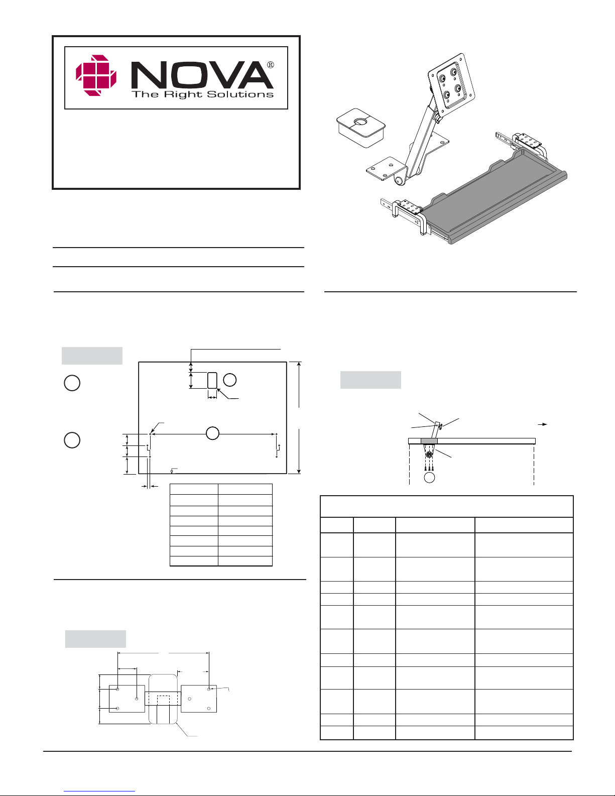
Step 1
Cut opening for grommet, (Figure 1). Note the grommet cut-out
distance from back edge of work surface. Insert grommet sleeve
(G) into cut-out.
1
1-
/16
”
(27mm) for
Figure 1
B
Grommet
Cut-Out
A
Keyboard
Drawer
Drill
Pattern
"
2
/
1
2
"
2
/
1
2
"
4
)
mm
(64
)
mm
(64
)
mm
(102
(
Offset 32mm)
1-1/4"
Typical
13
3-
”
3-¼
(82.6 mm)
3
/16" Dia.
5
/8" Deep
6 Places
(47.5 mm)
FRONT EDGE of WORK SURFACE
KB drawer size Dimension A
22"
24"
27"
28"
30"
33"
34"
/16
”
7
1
/8
A
(96.7mm) for
”
18
25
26
28
22
31
321/8" (816 mm)
18” or 24” D Surface
30” D Surface
B
5/16" R.
4 places
(8 mm)
13
/16" (478 mm)
19
/32" (574 mm)
5
/16" (643 mm)
1
/8" (664 mm)
1
/16" (713 mm)
1
/4" (794 mm)
Step 2
Using the template provided, drill holes for the Surface Mount
Arm bracket on underneath side of work surface. Holes should
be centered over grommet cut-out, (Figure 2).
Figure 2
1-1/4"
(32 mm)
1"
(25.3 mm)
1.26"
(32 mm)
1"
(25.3 mm)
P.O. Box 725 • 425 W. Industrial Avenue • Effingham, IL 62401 • Phone (800) 730-6682 • Fax (800) 940-6682 • info@novasolutionsinc.com • www.novadesk.com
IIR030_SMA-1-0203 Instructions ©Nova Solutions, Inc. 2011 Patents pending.
6"
2-1/16"
(52.4 mm)
Underneath Work
Surface Drill Holes:
3/16" Dia.
5/8" deep
6 places
Grommet
Cut-out
Step 3
With the tubing of the Surface Mount Arm through grommet
cut-out, mount the Arm bracket underneath the desk top using
six (B) sheet metal screws, Figure 3. (NOTE: You may first have
to depress the Silver Safety Pin on tubing to separate the Arm
into two pieces).
Figure 3
Tubing through
18”
Min. Surface Depth
grommet cut-out
Silver safety pin
B
Position arm so that wing nut faces
user side of work station
Arm mounting bracket
Packing List
QTY REF # ITEM # DESCRIPTION
1 A SMA-1-0203-NK FPD Surface Mount
with Nova Keyboard
10 B 1412APPBO #14x3/4
Sheet metal screw
1 C Flat Arm Plate 75 mm VESA Plate
1 D Flat Arm Plate 100 mm VESA Plate
4 E 50900219 4MMX .7x10
Machine screw
4 F 10628-03819 4MMX .7x8 FH PH
MS Black Screw
1 G 50-8-1080 Grommet
1 H 20060126 Keyboard Hanger
with Glide - Left
1 J 20060127 Keyboard Hanger with
Glide - Right
2 K 50900032 #14x1-1/2” Screw
1 L Varies by size Nova Keyboard Drawer
Page 2
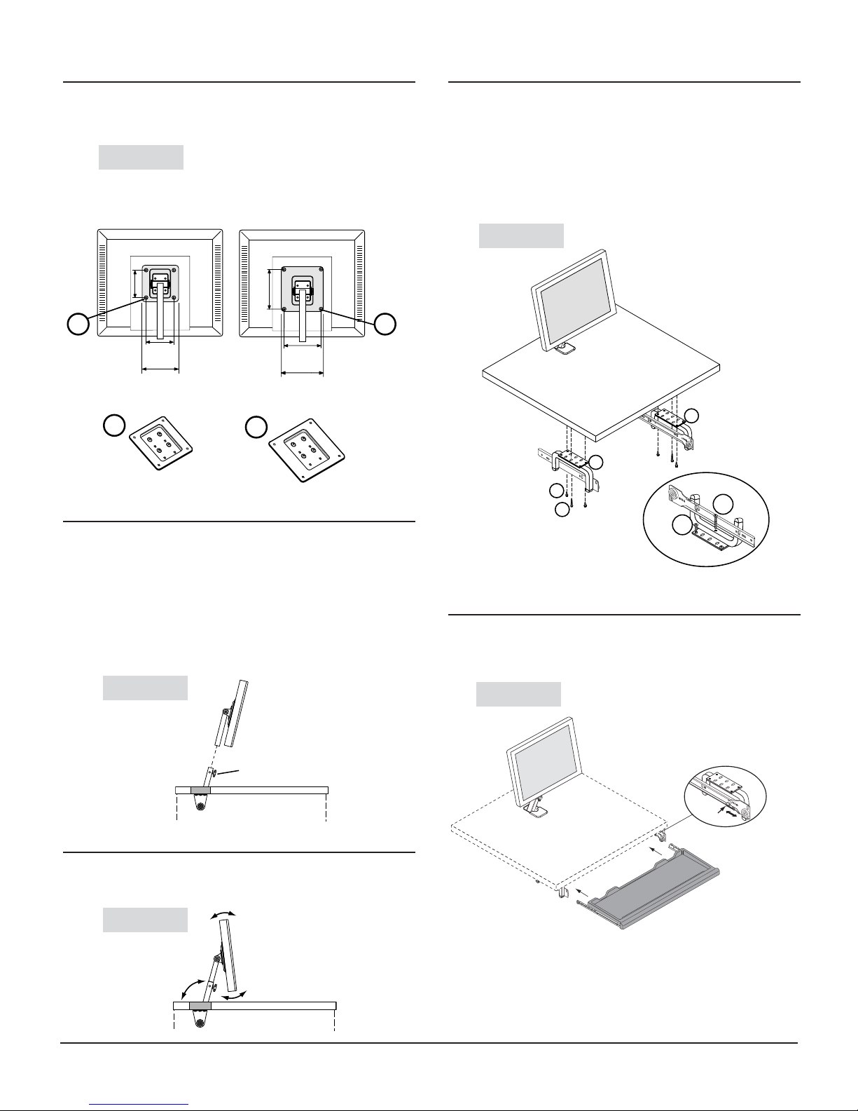
Step 4
Step 7
Remove flat panel display base. Attach flat panel
display to VESA plate (C or D) with screws (E, Figure 4).
Figure 4
Attaching VESA plate to Flat Panel Display
")
16
/
15
100 mm
(3-
100 mm
15
(3-
/
16
")
7
4-
/
16
"
100 mm VESA plate
D
E
75 mm
E
75 mm VESA plate
C
/16")
15
(2-
75 mm
15
/16")
(2-
3-3/4"
Step 5
Slide extension tube that is attached to VESA plate into
the extension tube protruding through grommet hole,
(Figure 5). After desired monitor height is reached,
tighten wing nut to ensure extension tubes do not slide.
When installing some Apple® flat panel displays, a
VESA Adapter (Model #50-8-4100) may be necessary.
Contact Customer Support for more information.
Attach keyboard hangers (H, J, Figure 7), to underside
of work surface with screws (B, K).
NOTE: The longer screws (K) pass through the tubular
section of the keyboard hanger. This allows the
assembly to be leveled by loosening or tightening the
screws.
Figure 7
J
H
B
K
K
B
Step 8
Slide keyboard drawer into glides. Pull outward locking
tab forward to lock keyboard drawer into place (Figure 8).
Figure 5
Figure 8
Outward
locking tab
Wing Nut
Step 6
Adjust flat panel angle to desired location by firmly
grasping top and bottom of monitor and tilting (Figure 6).
Figure 6
P.O. Box 725 • 425 W. Industrial Avenue • Effingham, IL 62401 • Phone (800) 730-6682 • Fax (800) 940-6682 • Email: info@novasolutionsinc.com • www.novadesk.com
IIR030_SMA-1-0203 Instructions ©Nova Solutions, Inc. 2011 Patents pending.
 Loading...