

Page 1

Copyright © 2014 Ikhwezi Solar (Pty) Ltd, Novatherm CC, Solar Assist (Pty) Ltd
Instruction Manual
for the Installation and Maintenance of
NovaSun Direct Freeze Resistant
High Pressure Solar Hot Water Systems
(October 2013)
For use by trained qualified personnel only. Applicable to the following models:
Novasun, Direct Freeze Resistant, 150l, 200l, 300l
We reserve the right to change the installation instructions.
Reproduction, even partial, is only allowed with written permission.
WE Geysers (Pty) Ltd ,7 Nelmapius Street,
Chamdor, Krugersdorp, 1754
novasun@solarassist.co.za
www.novasunsolar.co.za
Page 2

Copyright © 2014
Ikhwezi Solar (Pty) Ltd, Novatherm CC, Solar Assist (Pty) Ltd
1
Contents
1. Introduction ............................................................................................................................... 2
2. System description ..................................................................................................................... 2
2.1 Configurations .................................................................................................................. 2
3. Health and safety ....................................................................................................................... 2
3.1 General ............................................................................................................................ 2
3.2 Installation considerations ................................................................................................. 2
4. System configurations ................................................................................................................ 3
4.1 Novasun Thermosiphon System .................................................................................. 3
4.2 Novasun Split-pumped System .................................................................................... 3
5. Frost, scaling and hail resistance, stagnation................................................................................ 4
5.1 Hail resistance ............................................................................................................... 4
5.2 Freeze protection .......................................................................................................... 4
5.3 Direct systems – Freeze resistant ................................................................................ 4
5.4 Scale resistance ............................................................................................................ 4
6. System placement and orientation............................................................................................... 4
6.1 Collector orientation .......................................................................................................... 4
6.2 Shading............................................................................................................................ 4
6.3 Tilt angle .......................................................................................................................... 5
6.4 Water supply / delivery ..................................................................................................... 5
6.5 Roof structural integrity .................................................................................................... 5
7. Mounting methods ..................................................................................................................... 5
7.1 Selection of appropriate mounting method ......................................................................... 5
7.2 System mounting methods ................................................................................................ 5
8. Mounting process ....................................................................................................................... 7
8.1 Suggested mounting method 1 .......................................................................................... 7
8.2 Suggested mounting method 2 .......................................................................................... 8
9. System Installation ..................................................................................................................... 8
9.1 General installation technique ............................................................................................ 8
9.2 Cylinder and System plumbing ........................................................................................... 8
9.3 Geysers ............................................................................................................................ 9
9.4 Electrical connection ......................................................................................................... 9
9.5 Installation Diagrams ........................................................................................................ 9
Pumped System – Installation Diagram........................................................................................ 9
10. System commissioning ............................................................................................................. 11
10.1 Commissioning direct systems ......................................................................................... 11
11. Installation checklist ................................................................................................................. 11
12. System Selection and Sizing ...................................................................................................... 12
12.1 Introduction ................................................................................................................... 12
12.2 System sizing ................................................................................................................. 12
12.3 System type ................................................................................................................... 12
13. Owners operating and maintenance instructions ........................................................................ 13
13.1 Introduction ................................................................................................................... 13
13.2 Operating and efficient use ............................................................................................. 13
13.3 Over-night temperature stabilisation ................................................................................ 14
13.4 High water temperature .................................................................................................. 14
13.5 Periods of reduced usage or holidays ............................................................................... 14
13.6 Freeze protection liquid ................................................................................................... 15
13.7 Setting the time clock ..................................................................................................... 15
13.8 Owner maintenance ........................................................................................................ 17
13.9 Troubleshooting .............................................................................................................. 18
14. Warranties ............................................................................................................................... 18
15. Contacts .................................................................................................................................. 18
16. Warranty Contact Centre .......................................................................................................... 18
17. Warranty Services: (log warranty services) ................................................................................ 19
Page 3

Copyright © 2014
Ikhwezi Solar (Pty) Ltd, Novatherm CC, Solar Assist (Pty) Ltd
2
1. Introduction
All NovaSun solar hot water systems are high quality thermal solar
systems, using advanced technology to convert light into heat. This
installation manual must be read and understood before undertaking the
installation of a NovaSun solar hot water system. Should any aspect of the
installation process remain unclear a NovaSun Solar representative should
be contacted for advice prior to installation.
This manual does not seek to provide comprehensive guidance in terms of
the general plumbing and electrical connection of geysers, which is
assumed knowledge and required of any registered installer, but rather
sets out to provide guidance in terms of the correct installation of the solar
thermal components of the system.
Systems must be installed by suitably qualified and registered plumbers
and electricians, in accordance with relevant South African Norms and
Standards, National Building Regulations, Law and Regulations, Local ByLaws, including the following:
SANS 198 - Functional control valves and safety valves for domestic
hot and cold water supply.
SANS 10106 - The installation, maintenance, repair and replacement
of domestic solar water heating systems, edition three.
SANS10252 - Water supply and drainage for Buildings. Part 1 - Water
supply installations for buildings.
SANS 10254 - The installation, maintenance, replacement and repair
of fixed electric storage water heating systems.
SANS 10142 - The wiring of premises. Part 1 - Low-voltage
installations.
SANS 10400 - Parts A, B, L, XA.
Occupational Health and Safety Act (Act 85 of 1993)
National Buildings Regulations Act 103 of 1977
Water Services Act (Act N0 108 of 1977)
It is the responsibility of the installer to ensure that they and their staff
are familiar with and competent in respect of the above. Responsibility for
the safe and proper installation of a system rests with the installer.
The solar hot water systems referred to herein must be installed in
accordance with these instructions, local and national plumbing
regulations, municipal building codes and any other relevant statutory
regulations.
All intellectual property in this design and/or registrations and/or copyright
including any patent, patent application are the property of Novatherm CC
and/or WE Geysers (Pty) Ltd.
Observation of these instructions is most important and failure to do so
could void the benefits of the warranty.
The connection, attachment, integration or general association of other
equipment or parts which either directly or indirectly affect the operation
or performance of the solar system could void the warranty. Other such
equipment or parts not supplied by WE Geysers (Pty) Ltd, which may
affect its operation/performance must first be authorised by WE Geysers
(Pty) Ltd in writing if the full benefits of the warranty are to remain valid.
WE Geysers (Pty) Ltd does not accept liability or responsibility for the final
fitness of water for consumption from this water heater, as the water
quality is not affected by the system and is a function of the municipal
and/or other water supply.
This manual has been written with the intention of ensuring that the
system is correctly installed and that the owner/user is fully conversant
with the best methods of operation.
2. System description
2.1 Configurations
NovaSun solar hot water systems utilise state of the art technology and
perform with high efficiency in a wide range of weather conditions.
Collector output is directly related to the amount of incoming solar
radiation striking the collectors. This installation manual covers the
installation of the following systems:
Model Major System Components
NovaSun
150l
150 Litre Solartherm Direct Geyser
1 x 1.7sqm NovaSun Collector
NovaSun
200l
200 Litre Solartherm Direct Geyser
1 x 2 sqm NovaSun Collector
NovaSun
300l
300 Litre Solartherm Direct Geyser
2 x 2 sqm NovaSun Collectors
The models governed by this manual are pumped and thermo-siphon
systems. Thermisiphon systems may be installed in a close-coupled or split
system format whilst pumped systems are installed in split system format
and water is circulated using an applicable water circulation pump.
The NovaSun range of solar hot water systems are direct freeze resistant
systems.
System heating performance
Model Q-Factor*
Energy
Rating**
NovaSun 150l 11.8 TBA
NovaSun 200l 16.3 TBA
NovaSun 300l 27.5 TBA
*The thermal performance of the systems have been established by the South
African Bureau of Standards in terms of SANS 6211, at an incoming radiation of 16MJ
per m² per day, a temperature differential of 10°C and at an inclination of latitude
plus 10°.
**Q-factor is calculated in mega-joules whereas the energy rating is calculated in
kilo-watt hours. The energy rating is calculated by converting the q-factor into kwh.
The specific thermal capacity of the NovaSun collector is 4.39KJ/K m².
3. Health and safety
3.1 General
This appliance is not intended for use by young or infirmed persons
without supervision.
Scalding occurs at 50°C. This appliance is capable of providing hot water
over this temperature. In certain circumstances the system may expel hot
water and relieve pressure through the temperature pressure valve. Never
block this valve and always leave open to the atmosphere. Take care to
avoid contact with water when valve is in discharge.
This appliance is a water heating apparatus only and the final quality of
water and fitness for consumption is dependent on the quality of water
supplied to the system.
These systems are designed for the supply of hot water to domestic
household premises which have been constructed to the appropriate local
and national codes and regulations.
3.2 Installation considerations
All installations are to be carried out in accordance with the Occupational
Health and Safety Act (Act 85 of 1993) requirements and any relevant
local authority prescriptions. Some general points to take note of,
however, include the following:
Page 4
Copyright © 2014
Ikhwezi Solar (Pty) Ltd, Novatherm CC, Solar Assist (Pty) Ltd
3
Assess site specific risks and eliminate or reduced to an acceptable
level so as to satisfy health and safety requirements, prior to
installation.
Water temperature can reach boiling point and the collector can reach
stagnation temperatures of over 70°C. Shade collectors during
installation to prevent heating.
Take care when handling collectors to prevent breakage to glass and
injury. Safety goggles, work wear and gloves must be used to reduce
risk of injury.
Be aware of overhead power lines coming in through roofs, as well as
electrical wiring running through ceilings.
Assess weather and postpone roof work if unsafe (e.g. high winds,
rain, lightning, etc.).
Scaffolding and safety equipment must be installed by certified
personnel and signed-off accordingly. Inspect before use.
Inform home owners or building occupants of time and place of work
to be carried.
Ensure occupants are aware of site access constraints and all health
and safety implications relevant to them. Cordon off the area, if
applicable, to prevent personal injury and ensure any pets are
secured.
Ensure personnel working on installation are competent and in suitable
physical condition. Installers must be trained and conversant with the
assessment of height hazards, working at height safety procedures,
assessment of safety equipment (e.g. scaffolding, harnesses, etc.) and
the use and wearing of safety equipment (e.g. goggles, hard hats,
gloves, etc.).
All personnel working on the installation of a solar hot water system
must be issued with the appropriate safety equipment and be trained
in their use.
Failure to observe
safe practices may
result in:
scalding /
burns;
electrical
shock;
and/or falling,
which can cause
serious injury or
death.
4. System configurations
4.1 Novasun Thermosiphon System
For the purposes of the Eskom Rebate Program only thermo-siphon systems
can be installed and a rebate claimed.
A thermo-siphon system relies on the natural circulation of fluid between the
collector and the geyser. In order for the thermo-siphon process to occur
the geyser must be placed in a higher position than the solar collector. The
system operates according to the laws of thermal dynamics (i.e. a liquid,
when heated, becomes less dense and rises above the denser cooler liquid).
Heated water rises up through the collector and into the geyser, displacing
colder water therein, which sinks to the header pipe of the Novasun
collector. The process continues until the collector can add no more gain in
temperature or until the sun stops shining. Without sunlight the water in the
collector header pipe cools, becomes denser, preventing hotter liquid in the
geyser from being displaced.
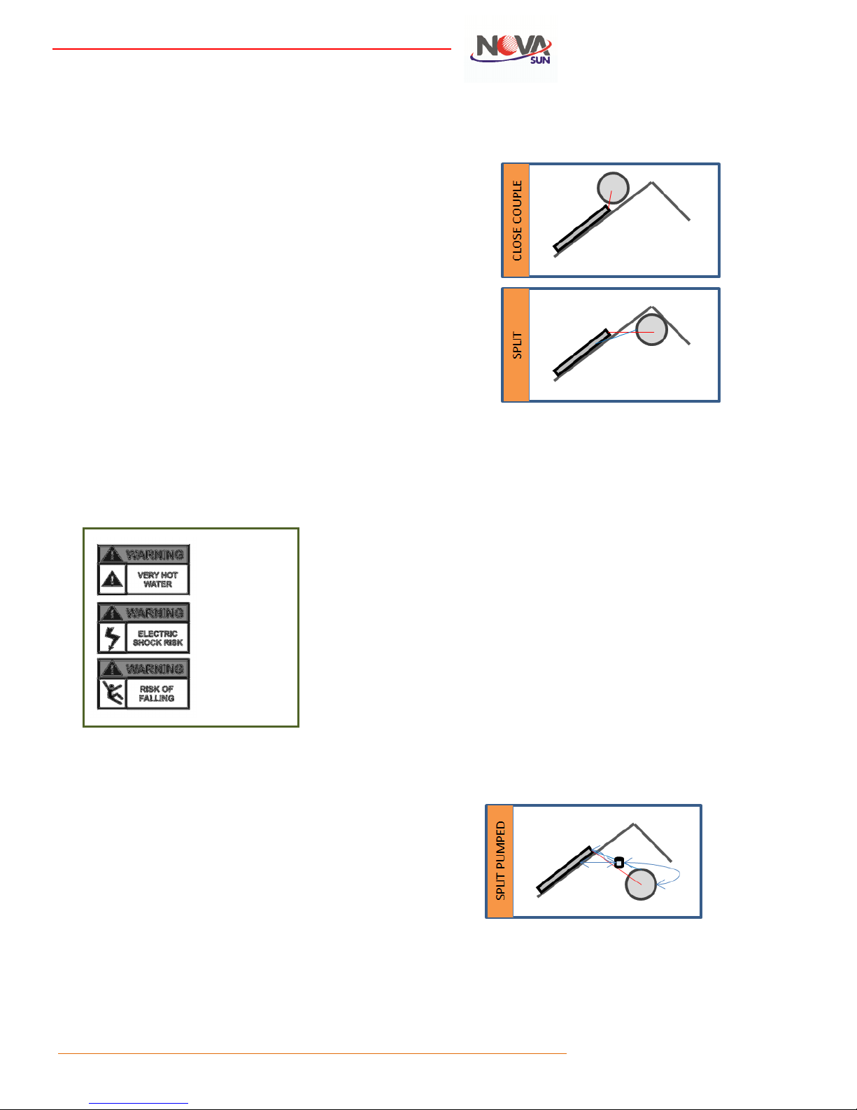
A thermo-siphon can be close-coupled or split as illustrated below, provided
there is sufficient roof space.
4.2 Novasun Split-pumped System
• Where the solar water heater is installed in the roof, it must be
installed in compliance with SANS 10106 complete with a Safety Valve,
drain cock, Multi Pressure Control Valve 400kPa, Drip Tray and vacuum
breakers on the cold and hot water supply.
• When installed inside the roof minimum clearance must be allowed in
order to remove the element and thermostat.
• Roof structural integrity must be handled according to section 6.5.
• For Product warranty detail refer to the separate Warranty Agreement.
• Pump Circulation in the Novasun SWH system.
• When it is not convenient or possible to place the cylinder higher than
the collector, a circulating pump controlled by an electronic control unit
and two sensors is used to monitor the temperature of the manifold
and the cylinder, that enable the powering of the circulation pump
when the water in the panel manifold is hotter than the water in the
cylinder.
• When the temperature difference is less than the set point the pump
will stop
• When temperature of water in the cylinder reaches the highest set
point, the controller will stop the pump.
• The circulating pump used must be installed and maintained according
to the manufacturer’s instructions.
• A 12V circulating pump with a photovoltaic can also be used.
• A split-pumped system is illustrated below.
Page 5
Copyright © 2014
Ikhwezi Solar (Pty) Ltd, Novatherm CC, Solar Assist (Pty) Ltd
4
5. Frost, scaling and hail resistance, stagnation
5.1 Hail resistance
NovaSun collectors are hail resistant with 4mm toughened glass and have
passed SABS hail tests.
5.2 Freeze protection
Solar hot water systems can be classified as (i) direct: freeze resistant, (ii)
direct: non freeze resistant or (iii) indirect.
5.3 Direct systems – Freeze resistant
In direct systems the water to be used in the household circulates through
the collector, transferring solar energy into the solar geyser.
The Novasun panel contains a fully insulated heat exchanger that acts as a
freeze resistant mechanism, as declared by the manufacturer. The pipework
connecting to the solar geyser must be insulated with Insulflex insulation
material.
When installed with a PEX-lined Solartherm Cylinder it can be used in all SA
climate locations (i.e in areas where frost occurs and areas, where ambient
temperature may fall below 5°C). Contact Solar Assist to discuss water
quality matters.
5.3.1Direct systems: non-Freeze Resistant
In direct systems the water to be used in the household circulates through
the collector, transferring solar energy into the solar geyser.
Direct systems are used in frost-free locations, where ambient
temperature never falls below 5°C and where water quality is good (i.e. less
than 600ppm total dissolved solids/minerals).
5.3.2Indirect systems
In indirect systems the potable water used in the household does not
circulate through the collectors, but remains in the geyser and is heated
indirectly by a heat exchanger.
There are two basic types of heat exchanger, namely a jacketed system
where an inner cylinder is surrounded by a secondary outer layer and an
internal heat exchanger where the solar geyser contains an internal copper
pipe structure.
In both cases the solar loop (i.e. the pipe work to and from the collectors)
contains a heat transfer medium (i.e. propylene glycol/water solution) which
is physically separated from the potable water.
Propylene glycol has a lower freezing point and prevents the liquid in the
collectors from freezing and damaging the collector through expansion that
occurs when ice forms. Only food grade glycol should be used.
Indirect systems are used in locations where frost occurs and the
ambient temperature drops below 5°C and/or where water quality is
poor (i.e. more than 600ppm total dissolved solids/minerals).
These collectors are resistant to freezing only when installed with an indirect
geyser and the solar loop filled with a solution of propylene glycol and
water. Water alone must not be used as a transfer fluid. The glycol / water
solution should be mixed in a glycol to water ratio of 1:3 (i.e. 33% glycol).
5.4 Scale resistance
Indirect systems containing a glycol solution also prevents scale build up
inside the collector in areas of poor water quality. It is important to note that
the geyser itself may still be affected by water quality as would be the case
with any conventional enamel-lined geyser unless a Solartherm PEX-lined
geyser is used.
If a direct system is used in areas of poor water quality the pipe work inside
the collector and solar loop may be subject to a build-up of scale. This may
be avoided through the use of a water softening system. This is good
practice regardless of type of system, as the water will affect other
household appliances in any event.
In the event collectors experience scale build-up the performance
of the system will decrease. Should this occur the system can be
flushed with a mildly acidic solution (e.g. vinegar solution) and in
the case of the Novasun collector, the Header Pipe should be
flushed. The pipe work should then be flushed with fresh water
after removal of scale prior to re-commissioning.
Ensure you are familiar with the relevant tank manufacturer’s warranty
terms and conditions in respect of water quality, particularly as it relates to
anode replacement in case of enamel-lined tanks.
6. System placement and orientation
A number of basic fundamentals need to be observed when installing any
solar hot water system.
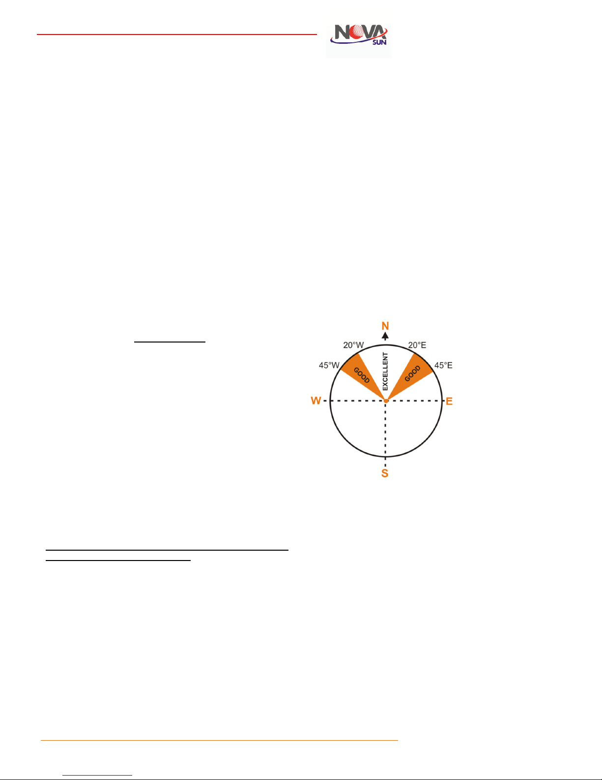
6.1 Collector orientation
Optimum system performance is achieved when the collectors face directly
North (i.e. true North) when installing in the Southern Hemisphere. The
closer the collector is to directly facing the equator the greater the amount
of solar radiation the collector will be exposed to and the greater the
potential for heating.
Angles up to 45° either side of North will not have a major effect on the
system performance given the state of the art technology used in the
construction of the NovaSun systems. Therefore, roofs that are orientated
away from North are also acceptable for installation.
Outside of the 45° range one could consider utilising more collector surface
area or using a mounting frame to adjust the orientation back to North.
6.2 Shading
With a system orientated to face North, the time period when the collector is
exposed to the most direct solar radiation is between 10h00 and 16h00.
Solar collectors with an East bias will achieve a greater gain in morning
hours and those with a West bias will do so in the afternoon.
Care should be taken to ensure that the collectors are not subjected to
excessive shading from trees or adjacent buildings, particularly between
09h00 and 16h00.
Also bear in mind that tree growth could lead to future shading issues.
If the installation takes place in summer, it is also important to take into
account the lower solar angles in winter, which result in longer shadows.
Page 6
Copyright © 2014
Ikhwezi Solar (Pty) Ltd, Novatherm CC, Solar Assist (Pty) Ltd
5
6.3 Tilt angle
In respect of the optimum angle of inclination for a solar collector, the rule
of thumb provides that the latitude of the location is taken and then 10°
added thereto. Therefore, a location with latitude of 25° would indicate an
optimum collector tilt angle of 35°.
The angle of inclination, however, is also flexible and minimal loss of
performance occurs by installing at lower or higher angles of inclination.
The NovaSun collector can be installed as low as 10°. Below this, however,
the thermo-siphon process does not function effectively. Also, angles lower
than this would result in build-up of dust, as it is not able to be washed
away effectively by rainfall.
It must also be noted that installation angles over 30° will require additional
strapping to secure the geyser and collector during and after installation, as
at this angle the system will tend to move downward. Consideration should
be given to a split installation in these circumstances.
6.4 Water supply / delivery
The location of the installation should give as efficient a supply of hot water
to all areas of the residence as possible. If not possible, the system should
be placed as close to its main point of usage (e.g. master bathroom).
Discuss this with the client and confirm their understanding and
requirements.
6.5 Roof structural integrity
The area chosen for installation must be structurally capable of handling the
loading. Check load weights of applicable system and ensure that the weight
can be borne by the roof structure. Specialist advice should be sought if
required.
The system should be placed, such that the tank spans at least three main
trusses. It is good practice to brace all truss work that supports the
installation.
Strengthen rafters (or timbers or other structures) used for supporting the
panel and tank, for example by adding noggins between rafters or adding
thicker timbers alongside them or cross bracing them or adding additional
supporting struts to the truss to spread the additional load to a load bearing
point. Where ever possible the system should be installed over a supporting
wall of the building (i.e. on a truss resting on a supporting load bearing
wall). Never install a system on a roof with damaged or rotting timbers.
To prevent cracking of certain fibre cement and metal roof sheeting, a flat
mounting frame designed to spread the load of the geyser and its contents
should be designed by suitably qualified personnel and installed below the
geyser. Ensure that the roof covering material is structurally sound to
receive the weight of the system. In the case of a split system installation a
wooden frame should be constructed which raises the tank above the level
of the collectors. Care should be taken in the design and construction of this
frame so as to ensure it meets all relevant standards.
7. Mounting methods
7.1 Selection of appropriate mounting method
Please note that it is the installer’s responsibility to ensure that the means of
fixing the system to the roof such that it results in a safe and functional
installation.
The methods suggested are generic and will not necessarily be suitable in all
situations.
7.2 System mounting methods
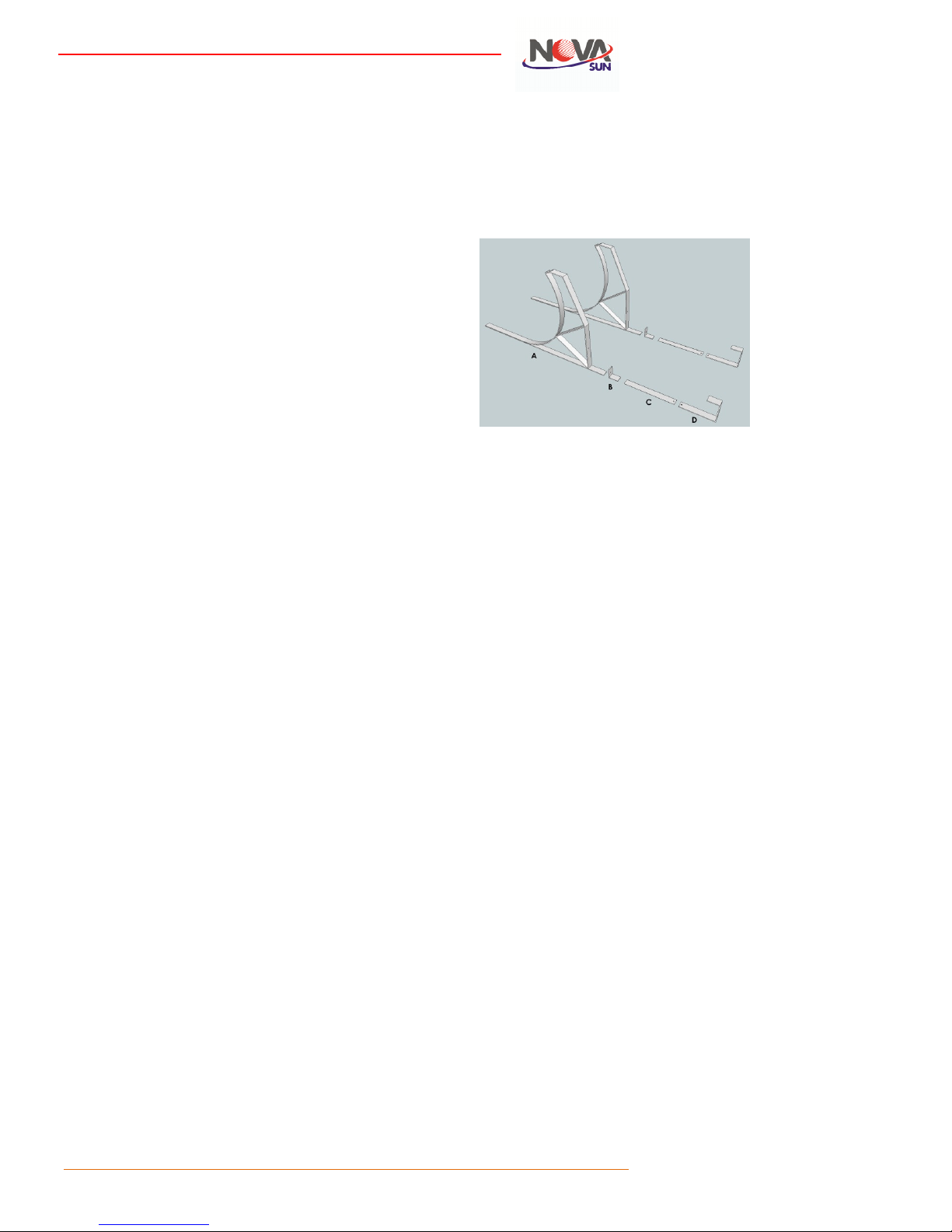
7.2.1Suggested method 1 - General purpose installation brackets
The image below depicts a typical bracketing system which could be used
with NovaSun solar hot water systems. This type of bracketing system is
suitable for tiled or corrugated roof structures with a pitch of less than 30
degrees. Typical kits would include the following pieces:
A (2 pieces) – Tank Cradle Bracket
B (2 pieces) – Collector Clamp
C (2 pieces) – Straps (not included*)
D (2 pieces) – Collector Hanger Bracket**
*Straps are not included as lengths required will differ from installation to installation.
These should be aluminium or stainless steel.
**Please note that two hanger brackets are required per collector. The 300 litre
system using two collectors require 4 hanger brackets (two per collector).
Please note that points of contact between the collector frame and mounting
brackets and between tank and mounting brackets are buffered by a foam
lining to prevent issues surrounding galvanic corrosion.
The installer must install the system in such a fashion to prevent long term
degradation of system materials through galvanic reaction.
7.2.2Suggested method 2 - Alternate installation brackets
As an alternative to the first bracketing system, straps could be used.
Collectors could be secured directly to the roof structure, at each of the four
corners of the collector, by means of aluminium strapping.
The straps should be securely fixed to the underside of the aluminium
collector frame using aluminium speed screws. The straps can then be
passed under the tiling and secured around the nearest truss and/or purlin.
In respect of the geyser, strapping can be hooped around the geyser, on
either end of the cylinder, using strap clamps available with commercially
available strapping systems, leaving enough length to pass the tail pieces
under the tiles and secured around the appropriate roof woodwork.
As indicated above the installer must install the system in such a manner so
as to prevent galvanic corrosion between system components and the
mounting brackets and/or straps.
Page 7

Copyright © 2014
Ikhwezi Solar (Pty) Ltd, Novatherm CC, Solar Assist (Pty) Ltd
6
7.2.3Suggested method 3 alternate installation brackets
Geyser Brackets
a) Description: Profiled aluminium plating providing a solid footing
distributing the weight of the unit over the roof covering. Positioning of
bolts on brackets are off centre in order to allow the foot plate of the
geyser to rest squarely in the centre of the bracket once installed.
Easy to use wing nuts are supplied to minimise effort on installation.
The foot plate of the geyser has to be fitted to the geyser
before
the
bracket is fitted onto the foot plate.
b) Once the roof covering is moved away, the stainless steel strapping
attached to the bracket is then wrapped around timber roof structure
for anchoring the bracket. Be sure to secure the strapping onto the
timber using tech screws or similar. Roof covering is then placed back
into original position.
c) The bracket is placed underneath the geyser foot plate with the bolt
sliding through the slotted hole and tightened using the wing nut as
supplied.
d) Note the correct use of “left hand” and “right hand” bracket.
Attached strapping is then tightened onto the timber structure in the
same way as above.
NovaSun tanks are equipped with extra anchor points on the
tank in order for the tank to be installed on an angle of 31° if
so required on pitch roofs.
Panel Bracket
a) Description: Holding bracket attached to stainless steel strapping
.
b) The holding bracket is positioned underneath the panel in order to
hook onto the bottom lip of the panel. The stainless steel strapping is
then fastened onto the roof structure in the same way as the strapping
of the tank.
The holding brackets should be placed in position first and properly
fastened to the roof structure using tech screws or similar. The roof
covering can then be placed back into position and the panel positioned
and secured into the holding bracket.
Page 8

Copyright © 2014
Ikhwezi Solar (Pty) Ltd, Novatherm CC, Solar Assist (Pty) Ltd
7
8. Mounting process
8.1 Suggested mounting method 1
Connect hanger bracket (D) to strapping (C), allowing enough length
strapping for the flexible strapping to fit under the roof tile and wrap around
the purlin/truss. Remove roof tiles and position hanger brackets.
The bracket should be secured in place by fixing to the purlin. Fixings (i.e.
screws, bolts, etc.) must be appropriate for the type of timber. Hard woods
and soft woods require particular fixings. Fix the bracket in place as shown
in the next image.
Replace tiles once the bracket is fixed in place as shown in the next image. 2
brackets are required per collector.
The hanger bracket should be positioned on the peak of the tile and not in
the valley. This helps prevent pooling of water and degradation to the
brackets and possible leaks.
The collector is positioned into the collector bracket as demonstrated in the
image above. A slight kick of 25mm from the cold inlet side to the hot outlet
side of the collector is recommended (i.e. cold side lower than hot side by
25mm).
In the case of sheet roofing, as depicted in the following image, a roof screw
can be removed, the strap placed over the existing hole and the roof screw
reinserted thereby securing the strap. In instances of sheet roofs,
appropriate waterproofing needs to be effected to the roof surface after
straps have been secured to the roof material.
The tank cradle (A) is positioned up against the top edge of the collector,
with the foot of the cradle slid underneath the collector.
The collector clamp (B) is fixed to the tank cradle to lock down the top of
the collector as depicted in the next image.
The tank cradles should also be placed on the peak of the roof tile. Once the
tank cradles are in place and the collector clamp fixed in place the geyser
can then be positioned into the cradles as pictured in the next image.
Page 9

Copyright © 2014
Ikhwezi Solar (Pty) Ltd, Novatherm CC, Solar Assist (Pty) Ltd
8
Make sure that the tank is rotated to a position where the drain cock is at
the lowest point on the geyser as pictured above. This will ensure that the
maximum volume of water in the tank is available to be heated by the
collector.
The image below depicts the completed mounting of the system.
Larger tank sizes may require additional tank cradle brackets depending on
the roof pitch.
8.2 Suggested mounting method 2
As an alternate to collector hanger brackets, aluminium straps could be used
to secure the collector. Aluminium friendly speed screws can be used to
secure the strap to the back of the collector frame. A strap needs to be fixed
to each corner of the collector frame (i.e. four straps).
Straps should be long enough to be fed underneath the roof tiles and then
folded around the timberwork of the roof. The straps should be positioned
on the peak of the tile and not the valley to prevent water from pooling and
degrading the strap. The straps used should be of sufficient gauge to
provide for a secure mounting of the collector.
The image below depicts the view from below, with a tile removed. This
demonstrates the strap fixed to the frame of the collector and then folded
around the purlin. Fixings appropriate for the type of timber should be used
(i.e. hard woods and soft woods require particular fixings).
In respect of the geyser, stainless steel strapping can be hooped around the
geyser, on either end of the cylinder, using commercially available strap
clamping ystems or other secure means of completing the hoop, leaving
enough length to pass the tail pieces under the tiles and secured around the
appropriate woodwork with appropriate fixings.
As shown in the image below, the strap should fit closely around the body of
the tank. Make sure that the tank is positioned in such a way that the drain
cock is at the lowest point of the tank. Once the tank is in place, fix the
hoop in place and replace tiles.
9. System Installation
9.1 General installation technique
During fitting and prior to filling, the system must be protected against the
entry of dirt and water. After the system has been mounted, it must be
flushed in order to remove any debris (e.g. metal chips, packaging residue,
sawdust, etc.).
Shade panels until after connecting plumbing and installation is ready for
commissioning in order to prevent heating of empty collector.
Exercise caution during the lifting phase of installing the collector and tank
onto the roof. Ensure that adequate personnel are present to bear the
weight and that they are assisted with supportive lifting tethers and safety
rigging.
With reference to section 6 above, measure the size of the collector, and use
measurement to locate the best position on the roof to affix panels,
matching measurements to supporting roof trusses and purlins. Avoid
interference with coping or gutters.
A minimum distance between the top of the panel and the tank flow outlet is
300mm. In split system installations distances should be kept as short as
possible and generally should not exceed 3 metres.
For roof pitches above 30°, special and/or extra strapping or brackets may
be required to prevent downward movement of the tank and collector.
Measure the exact size of your tank and use this to locate the best position
on the roof at which to affix tanks to supporting roof trusses and purlins.
If necessary, strengthen rafters used for securing the panel and tank, for
example by adding noggins between rafters or adding thicker timbers
alongside them (refer section 6.5 above).
9.2 Cylinder and System plumbing
9.2.1General
Plumbing must conform to IOPSA code, SANS, PIRB and local regulations.
In a thermo-siphon the geyser is installed above the panel, but kept as close
as possible.
All piping runs should be kept as short as possible, both between the
collector and tank, as well as between the tank and the location of hot water
usage (i.e. bathrooms).
Page 10

Copyright © 2014
Ikhwezi Solar (Pty) Ltd, Novatherm CC, Solar Assist (Pty) Ltd
9
All pipework must be properly insulated, including at least two metres of the
cold feed to and hot supply from the geyser. Insulation material must be
heat tolerant and UV resistant, nor must it unduly compress or cause
corrosion.
Installation Tip: For increased weatherability in harsh climate areas insulation can further be wrapped with aluminium duct
tape or covered by a product such as Flash Harry membrane and coating.
Piping from the flow of the tank to the inlet at the top of the collector must
have a continuous fall and from the top of the collector to the return must
have continuous rise.
Only hard-soldered connections or compression fittings are to be used in the
assembly of the solar heating circuit. No fluxing agents containing chloride
should be used.
Use copper pipe only. Plastic pipe must not be used due to the effects of
high water temperatures and pressures. The pipe work to and from the
geyser must also be copper for at least two metres below the hot water
outlet.
A temperature mixing valve must be used to control the temperature of
water delivered to the points of use. This is important in the prevention of
accidental scalding and is a SANS requirement.
9.3 Geysers
The Novasun Solar Water Heating systems make use of WE Geysers (Pty)
Ltd’s Solartherm geysers cylinders, depending on the model selected. The
manufacturers’ installation requirements that accompany each of these
products must be observed in the installation process. Failure to do so may
result in the warranty of these products becoming null and void.
WE Geyser tanks are fitted with SABS approved peripherals.
Geysers installed inside must have sufficient space for servicing thermostats
and elements (Note: there are no anodes in Solartherm cylinders which
require regular servicing) , as well as allowing for the required SANS height
of vacuum breakers above the tank
9.4 Electrical connection
All electrical work must be carried out by properly qualified and registered
electricians.
Novasun recommends the installation of a time switch when undertaking a
solar installation. This optimises the performance of the system and is
specifically required when a rebate is to be claimed in respect of the Eskom
incentive program.
The time clock is fitted to the distribution board and is used to set the time
periods that the thermostat and element receive electrical input. Time
settings will be dictated by patterns of consumption, but for example could
be set to activate from 3am to 5am and from 4pm to 6pm, taking care that
the times do not fall within Eskom peak periods.
Electric water heaters use 220 Volt AC power. The circuit breaker and
isolator should be switched off before working on the geyser. Verify that
power is off with a volt meter and ensure that load shedding or existing
timers are not active, which may cause the electrics to become live whilst
working on the system.
Power should not be applied to an empty electric water heater as heating
elements will be damaged. Tank warranties would be void in these
circumstances.
9.5 Installation Diagrams
Various installation diagrams are illustrated below in order to assist
installers with installation services. Prospective installers must
contact Solar Assist for system specific training and instructions
prior to installing the Novasun SWH range.
Thermosiphon System – Installation diagram
Acknowledgement: www.solarassist.co.za Note: For purpose of installation demonstration no insulation
has been shown here but Insulflex insulation must be installed according to standard on all open copper
piping as per paragraph 9.3.1
Pumped System – Installation Diagram
Note: For purpose of Pump controller installation and wiring instruction refer to the Geyserwise Installation
manual or go to www.geyserwise.co.za
Page 11

Copyright © 2014
Ikhwezi Solar (Pty) Ltd, Novatherm CC, Solar Assist (Pty) Ltd
10
Pumped Controller – Geyserwise System
Acknowledgment: Geyserwise Installation Manual: For purpose of Pump controller installation and wi ring
instruction refer to the Geyserwise Installation manual or go to www.geyserwise.co.za
Page 12

Copyright © 2014
Ikhwezi Solar (Pty) Ltd, Novatherm CC, Solar Assist (Pty) Ltd
11
10. System commissioning
10.1 Commissioning direct systems
Make sure that the solar radiation is low during
filling. In strong radiation it is possible for steam to
form in the collector. Keep the collector covered
throughout installation and commissioning.
Do not turn on the electric backup until the tank
has been filled with water.
Turn on at least one hot water outlet tap and open
the mains water supply to allow the water to fill the
tank and collector, expelling air from the tank. As
soon as water flows freely, without air sputter,
close the tap and allow the cylinder to pressurise.
Check all piping, joints and fittings for water leaks.
Check pressure relief valves to ensure correct
operation.
Turn on the electric backup element. Make sure the
tank is completely filled before turning on the
element. Ensure power is available to the backup
element.
Ensure the time clock has been correctly set.
11. Installation checklist
The following checklist should be observed by the
installer before handing the system over to the
owner/user.
All air bled from taps
System checked for water leaks
Cold and hot water pipes checked for leaks
Roof tiles back in position
Roof flashing watertight
Drain pipes free of obstruction
Pipework insulated
Electrical element, timer switch, isolator and
thermostat, controller and pump checked
Any protective plastic or packaging stickers
removed from tanks and/or collectors
Owner instructed on use
Page 13

Copyright © 2014
Ikhwezi Solar (Pty) Ltd, Novatherm CC, Solar Assist (Pty) Ltd
12
12. System Selection and Sizing
12.1 Introduction
Individuals purchase solar hot water systems for
many reasons. Some buy to realise savings on their
energy spend, others out of concern for the
environment, others as they have no other means
of heating water or it could be a combination of the
above. Whatever the motivating factor is it is
important that the type and size of the system
selected are going to best meet the consumers’
needs and expectations.
12.2 System sizing
In deciding on the system required, apart from
conducting a site visit to ascertain the proposed
installation site and associated mounting, plumbing
and wiring considerations, the sales representative
should also consult with the prospective customer
as to their hot water requirements.
It is critically important that the prospective buyer
provide accurate information in this regard, as the
results of providing incorrect information can result
in a system that either over or under performs,
given the specific needs of the customer.
The onus is on the prospective buyer to provide the
sales consultant with an accurate disclosure of the
hot water requirements and usage patterns in order
that a load profile can be formulated.
A load profile would include information such as
how many showers are taken per day and how
many litres are used, how many baths are taken
and size of baths, how much hot water goes
towards washing dishes and doing laundry, etc.
Only once this information is analysed can a final
recommendation be made on system size.
12.3 System type
System type can relate to a number of system
characteristics as follows:
Direct vs. Indirect (refer section 5 above)
Close-coupled vs. Split (refer section 4 above)
The decision between direct versus indirect is
described in section 5 above, but basically this is
determined by whether or not frost or poor water
quality dictate an indirect system.
NOTE: THE DIRECT NOVASUN
(THERMOSIPHON/PUMPED) SOLAR
WATER HEATING SYSTEMS CAN BE
USED IN ALL CLIMATE AREAS OF SOUTH
AFRICA
The decision between close-coupled and split
system is largely an aesthetic decision based on
customer preference, but there is a cost implication
in that split system requires additional plumbing,
system controller, circulation pump and mounting
structures which translate into a greater installed
cost.
As the NovaSun systems have been SABS tested in
a thermo-siphon and pumped configuration and
registered with Eskom accordingly, a split system
installation can be claimed for on the rebate
programme if the system is a thermo-siphon or
pumped system. That is, even though the tank is
installed inside the roof there is enough space that
the tank is above the level of the collector/s,
allowing a thermo-siphon to operate or a pump to
force the circulation.
NOTE: Please visit www.novasunsolar.co.za for
more information on system.
Page 14

Copyright © 2014
Ikhwezi Solar (Pty) Ltd, Novatherm CC, Solar Assist (Pty) Ltd
13
13. Owners operating and maintenance
instructions
13.1 Introduction
Dear Customer,
Thank you and congratulations on your purchase.
Your system is one of the most advanced available
and is proudly produced in South Africa.
It will provide years of service and savings. The
information below is provided to give guidance in
the effective use and maintenance of your system
and should be retained for future reference.
Yours sincerely,
WE Geysers (Pty) Ltd
13.2 Operating and efficient use
Savings in energy costs achieved is dependent
upon usage patterns and the extent to which
electrical backup is used. The following will assist in
understanding system performance:
Solar radiation is greater on clear, sunny
days, between 9am and 3pm. During periods
of use the system operates at approximately
twice the maximum ambient temperature and
during periods of non-use, it is possible to
achieve well over 90°C.
On days of high radiation schedule washing
loads as close as possible to mid-day.
On low solar radiation days avoid heavy hot
water usage.
Electrical backup, which is thermostatically
controlled and governed by a time-clock,
should be set at 55°C. The time-clock has
battery backup in order to prevent settings
being lost during general power failures. In
order to claim an Eskom rebate, a time-clock
is mandatory. We would advise the use of a
time-clock in any event, as this is the most
efficient method of operating a solar system.
Time-clock settings should, generally
speaking, be set for two hours in the morning
and two hours in the evening. For example, if
you bath at 06h30 and 18h00, set your timeclock for 04h00 to 06h00 and again for 15h00
to 17h00. Ensure backup time periods do not
coincide with localised load shifting by
municipalities employing ripple relay devices.
This will ensure that if there was not
sufficient solar gain during the day, you will
still have hot water in the evening and early
morning.
Solar systems without time-clocks rely on
thermostats to control when the element
switches on and off. This is not efficient or
cost-effective. An example of this would be,
using hot water in the morning which causes
the thermostat to automatically activate the
element to heat your water. However, this is
when the sun will start to heat your water.
Therefore, if you do not have a time-clock or
it is not programmed properly, you will not
save as much energy as you will use both
electricity and solar energy to heat your
water simultaneously.
An override function is provided on the time
clock so you can over-ride programmed
heating times and heat up your water
electrically. This should only be used when
strictly necessary (e.g. during periods of more
than normal usage when guests are in the
residence) and remembering to revert to preprogrammed settings. This will save you the
optimum amount of electricity and provide
the necessary reduction in peak-period use.
If you wish to set your timer differently, you
should discuss this with the dealer. However,
your timer must not come on during Eskom’s
peak electricity use periods. These may
change from time to time so please check
with your installer.
Page 15

Copyright © 2014
Ikhwezi Solar (Pty) Ltd, Novatherm CC, Solar Assist (Pty) Ltd
14
Once you get used to the system and its
optimum performance pattern, you may
eventually completely switch the electrical
backup off, particularly in summer months.
An additional benefit of this is that it is the
fastest way to reduce the system’s payback
period.
Savings can be further maximised by using
hot water in the evening rather than in the
morning, maximising the free energy
harvested during the day.
Additional tips to enhance savings include:
To further optimise energy and hot water
savings, install aerated shower heads and
aerators in taps to reduce hot water
consumption.
Insulate hot water piping to minimise heat
losses.
Showering generally uses less water than
bathing.
For health reasons your hot water system
should provide water at 55ºC, but not much
warmer than that. Do not set your thermostat
backup temperature control for temperatures
in excess of this.
If shading of collectors is experienced
between 9am and 3pm then corrective action
should be taken. Annually prune or cut trees
that shade the system.
Partial shading by chimneys, TV antennas,
roof erected fixtures, etc. on buildings during
these hours is acceptable provided that it
does not exceed 10% of the area. Shading
from newly erected buildings should be
checked and if system performance is
affected, relocation of the system may be
necessary.
13.3 Over-night temperature stabilisation
Over-night temperature stabilisation is the
reduction in water temperature, as the hot
water at the top of the storage cylinder
transfers some of its heat to the cooler water
in the lower section of the cylinder.
This effect is often perceived as heat loss, but
is actually the redistribution of stored heat
more evenly over the entire contents of the
storage tank. This may make it necessary to
use the electric element to raise the water in
the top section of the cylinder back to an
acceptable temperature.
Over-night temperature stabilisation is most
evident in the morning if the time clock is left
off overnight.
13.4 High water temperature
Your solar water heater will generate hot
water quickly and efficiently. Under normal
family use, it will operate between 60ºC and
70ºC. However, the temperature can exceed
this and under certain circumstances may be
as high as 95ºC. This can occur during
prolonged periods of direct sunlight and
particularly in summer or long periods of
reduced water usage. Extreme care should be
taken in these circumstances.
Although every system is fitted with a mixing
valve that regulates temperature at points of
water use, check the water temperature
before use, such as when entering a shower
or filling a bath or basin, to ensure it is
suitable for the application and will not cause
scalding. It is required by SANS regulations,
that a temperature limiting device / mixing
valve be fitted to the system. This will limit
the water temperature to 50°C at the point of
use. The risk of scalding will be reduced, but
water should always be tested prior to use to
prevent injury in the case of a tempering
valve failure.
13.5 Periods of reduced usage or holidays
If the water heater is left unused for two weeks
or more a small quantity of hydrogen gas, which
is highly flammable may accumulate in the top of
the water cylinder. This is true of both
Page 16

Copyright © 2014
Ikhwezi Solar (Pty) Ltd, Novatherm CC, Solar Assist (Pty) Ltd
15
conventional electric geysers and solar systems.
To dissipate this gas safely, it is recommended
that a sink hot tap be turned on for several
minutes. Do not use a dishwasher, clothes
washer or other appliance for this purpose.
During this procedure there must be no smoking,
open flames or any electrical appliance operating
nearby. If hydrogen is discharged through the tap
it will make an unusual sound like air escaping.
It is recommended that if the system is going to
be left unused for long periods of time, that the
backup element switched off at the distribution
board. Remember that when the geyser breaker
is reactivated the time clock may have to be reset
as it has a limited settings memory when
switched off (i.e. approximately 72 hours
depending on the model).
13.6 Freeze protection liquid
No freeze protection liquid is used in the Novasun
system.
13.7 Setting the time clock
WE Geysers (Pty) Ltd recommends that an SABS
approved time clock, with battery backup, be
installed on the distribution board. There are many
such time clocks on the market and the operation
of which are all relatively similar. A Samite QAT-RDM time clock has been selected to illustrate how
to program the time clock.
This time clock has four different screens. When it
is powered up screen 1 (main screen) appears.
SCREEN 1: Actual Time Indicator
This ON/OFF indicator indicates whether the time
clock is currently active or not. This screen also
displays the current actual time.
Press the green function button to cycle forward to
the next screen.
SCREEN 2: Set Actual Time
Press the Hour and Minute buttons to set the actual
time. Once the time is set press the function button
to advance to the next screen.
Page 17

Copyright © 2014
Ikhwezi Solar (Pty) Ltd, Novatherm CC, Solar Assist (Pty) Ltd
16
SCREEN 3: Program Timer On/Off
To program the desired timer settings press the off
button to move the flashing segment to the time at
which power is made available to the geyser
thermostat/element. Once the segment is at the
desired time, press the on button repeatedly to
insert 30 minute backup segments until the time is
reached when you want the backup period to end.
These steps can be repeated if further backup
periods are required. For effective operation an
afternoon and an early morning backup period are
recommended.
EXAMPLE: Backup period from 3PM to 6PM
Press the Off button until the program time
indicates 15h00, then press the On button until the
program time indicates 18h00. As shown below.
SCREEN 4: Bypass on or off
The timer programme is bypassed using this
screen. Press the “Bypass On’’ button to bypass the
timer and provide the geyser with a constant
supply. The Bypass on display flashes.
Press the “Bypass Off” button for power to be
controlled by the timer and switch on according to
the set times.
Press the function button to return to screen one.
Note: When in “Bypass On” mode the display will
not revert to screen one after 60 seconds.
Should you be away from home for any extended
period and you wish to switch the geyser off at the
breaker on the distribution board, please remember
that you would have to re-programme the time
clock on your return as the on-board memory is
only stored for approximately 72 hours without
being connected.
The use of the electrical backup is very much
dependent on personal usage patterns of hot
water. The following, however, are a few tips:
During days with temperatures below 20°C,
water temperature may only reach 40°C to
50°C. It could be lower if these colder days
are coupled with overcast and rainy
conditions.
The human body generally prefers
temperatures of between 35°C to 40°C for
bathing during winter and therefore boosting
may be required at certain times.
Page 18

Copyright © 2014
Ikhwezi Solar (Pty) Ltd, Novatherm CC, Solar Assist (Pty) Ltd
17
Backup heating is generally preferable during
late afternoon and early morning, so that
maximum use of solar energy during the day
is taken advantage of.
The backup should not be set that it is on
during periods when the water is being used.
This because an element cannot heat the
water with any efficiency when water is being
used.
If hot water use is heavy during the evening
then it is vital that a backup heating period
be set for the early morning if one desires hot
water first thing in the morning.
13.8 Owner maintenance
To ensure that the system will perform reliably,
some preventative maintenance should be
performed by the home owner/user. If the system
is in a position which is not easily accessible or the
owner is not in a position to effect the points
below, a service technician should be employed to
carry out the maintenance.
The following should be performed annually by the
owner/user or his appointed technician:
Wash the glass cover of the collector with a
mild household detergent. The collector glass
and seals should be inspected.
Mounting brackets and straps should be
checked for signs of wear.
Pipe insulation should be checked for signs of
degradation and/or damage. Please note that
although UV resistant insulation is used, the
harshness of the South African climate means
that the insulation will not last indefinitely.
There is no warranty on pipe insulation.
Visually inspect pipework for signs of leaks.
A periodic inspection of pressure reducing
valves, expansion valves, vacuum breakers,
temperature pressure valves and tempering
valves should be conducted on a solar geyser,
just as it should be done on any conventional
electrical geyser. These valves allow for the
safe operation of the geyser and should be
inspected twice yearly.
The temperature pressure (TP) valve is near
the top of the water heater and is essential
that this valve operates safely. It is possible
for the valve to release a little water through
the drain line during each heating period.
This occurs as heated water expands by
approximately 1L out of 50L of its volume. If
continuous leaking occurs this may indicate a
problem with the valve - please report this to
your installer immediately. WARNING - Never
block the outlet of this valve. TP valves
should be checked for performance at
intervals not exceeding 6 months, or more
frequently in areas of high incidents of water
deposits (such as Calcium or Magnesium).Be
advised that in areas or periods of high solar
radiation there will be greater frequency of
this valve opening. In order to check the TP
valve the easing gear should be operated.
This is a black knob on the TP valve that
needs to be turned in an anti-clockwise
direction and some water allowed to escape.
Be aware that this water may be at a high
temperature. Before opening the valve make
sure you are well clear and be advised that
the geyser will be under pressure so water
may be expelled at a high rate. Guard
carefully against exposure to the water
whether through direct contact or through
back splash. Be careful not to confuse the TP
valve with the solar relief valve fitted on
some indirect systems. Please contact your
installer for advice if unsure.
If at any point the temperature at point of
use (e.g. bathroom) appears to be increasing
or decreasing, the temperature mixing valve
may need to be set or adjusted accordingly.
Page 19

Copyright © 2014
Ikhwezi Solar (Pty) Ltd, Novatherm CC, Solar Assist (Pty) Ltd
18
Warning
When inspecting your system please bear the
following in mind:
The removal of the electrical cover plate on the
solar geyser will expose 220 V wiring. It must
only be removed by an authorised electrician or
service person.
Care should be taken not to touch the pipe work
connecting the solar storage tank and the solar
collectors. Very high temperature hot water can be
generated by the solar collectors under certain
conditions, and will flow through the pipe work
from the solar collectors to the solar storage tank.
Working at heights should only be undertaken by
suitably qualified personnel, using the proper safety
equipment.
Failure to observe safe
practices may result
in:
scalding / burns;
electrical shock;
and/or falling,
which can cause
serious injury or
death.
13.9 Troubleshooting
Should your system not provide hot water please
check the following before requesting a service call:
Shading from trees is not excessive and is not
covering the collectors for all or part of the
day.
Hot water usage has not been excessive.
Hot water is not leaking from within the
plumbing system that feeds hot water to the
points of use.
The time clock is operational and has been
programmed correctly.
The electric meter and/or display light on the
time clock speeds up when the time clock is
active.
Power has been provided to the main board
(i.e. no electrical faults or load shedding).
The ripple relay has not become jammed in
the open position.
The water supply to the home has not been
interrupted (i.e. municipal shut-off)
Please contact your local dealer and/or installer if
all of the above have been checked and there is still
no hot water. A charge out fee may apply if the
system is found to be functioning correctly and the
matter relates to one of the above issues.
14. Warranties
Please refer to the NovaSun SWH Warranty
Document.
15. Contacts
WE Geysers (Pty) Ltd (Pty) Ltd
Physical Address 7 Nellmapius Road, Chamdor,
Krugersdorp, 1754
Postal Address PO Box 4060, Luipaardsvlei,
1743
Tel +27 11 769 1387
Fax +27 11 762 2200
email info@novasun.co.za
email novasun@solarassist.co.za
Website www.novasunsolar.co.za
16. Warranty Contact Centre
SolarAssist 0861 106 618 (24/7)
Website: www.solarassist.co.za
Email: info@solarassist.co.za
Page 20

Copyright © 2014
Ikhwezi Solar (Pty) Ltd, Novatherm CC, Solar Assist (Pty) Ltd
19
17. Warranty Services: (log warranty services)
Important Notice: Making use of a non-accredited Solar Installer to perform warranty work on your
Novasun SWH system will void your Warranty Agreement.
Date: Service Provider/Contact detail Services/Job performed.
Owner Notes:
 Loading...