

Page 1
13"
PLANER
I·NSTRUCTION
MANUAL
Moder:
MB
1931
Page 2
CONTENTS
Ger8Al
WEfY'
lc::aE
MCllJt{Dt4C711-tE
~<:XJ<.
~~JOr.IS:
~
~a:F'
AD.JU.ST
~~
Q\lS'TAl.IJl'IG
SEm~
s.AfE1Y
~
P,l.,RTS
~."
Ra.l.ER,S
1HE
~
S\\IIT'O-I
DEI"ni
M.
niE
n-:IE
'DE
KJ'rrrlIFE
RULES
~
MB
PI.AI\IER
.................
MB
.............
a
-ruT'
[)EI'TH
~R
~ER
F~
POVtfER
1931
.....
....................................................
()I\ITO
**'1
..................................................
1931
..............
.................
....... " .•..
,.
••
".,
......
"'
..................................................................................................
".Il!
CJI=
CUT'
Kl'WES"
Kf\IIVEs
HElGI-IT''''+i-
•• , ••••
T(X)lS~
iIji
••
II!
•• , ...... ~ •••••••••
n-IE
wrx::t:J
11.+
••• " ••••••••••••••••
4
.........
1i.
.............
..............................................
SCAI.E
............
.......
,t."
.......................... _ ...........................
*
••
IfIi
••••••
Ii
••
*I
8AS.E
"
11
+
...
.,41
.............
*
....
III
..... " ••
........... , ...................................... " ............
...........................................................................................
'''
...........................................
tt
.............
................................................
•.•
u
''''
.................. " .........
.................
,,,
"
...
Ii
.......................................................
..........................................................
,.
......................................
,.
....... " ..........................
*
..................................
."
........................................................
....................
'''
.......
*.*1111
It
................
............................
111
,+u
"
••• " .......................
"""
.... " .............................
·.,.
.................
...
.,
.........
l1li
••••••••••••••••••••
11.4
............
"
...... , •••••
iII
.........
"
.................
11
••••••
+
••••
•••••••
11
••••••
1
..
1
3
411
•••
4
5
6
1'7
8
9
++.10
" ..
11
12
13
1~
ADJtJST
MAklf\lC;
~
1'tiE
T
A8lf:
11-IE
0J1l"ERHEAD
f()Il
FINiSH
EXrENSI~
AND
.............•........• _ ....•.......••.•........•••••••••
l.UBRJCA.~AAAI~
~
.........
.,
...............................................
P..A.RTS
u~,/DIA~.t.'Ii!
•••••••
4!
RalER.
•.
i
•••
..............
T.ABlE
P.ARAllEL
•••
U
......................................................................................
IIi*
.... I
.....
+
...... " .........
, ............................ u
•.•.•.•.•.
n
................................
*
..................................................
Ii
•••• " ....................
"'
•••• " ........
.,..~.1''''
••
-If!+
....
...................................
"
•••
~'I!
....
*
....
tI
•••
11
...........
it'
•••• , ..........
"
"
................
............
''.Ii
........
15
16-17
18
19
20-
22
23·31
Page 3

GENERAL
SAFETY
RULES
FOR
POWER
TOOLS
WARNING.
completely
...
ult I ••
owners manual and review frequently for continuous safe operatjon.
I.
laaw
application
machine~
2.
Ma'e
it
should
disable the third prong.
3.
K
••
p guards
maintenance
4
..
a
....
adjusting
5.1.,
Do
not
attempt
aU
instruc'tions. rules. etc. contained in
eeld
••
tllavolyll,
your
mach I
and
IVre
aU
be
v.
adlu.'111 keys aft
wrenches are removed from
work
are.
•••
limitations.
'eol,
aN
used
with a three-hole electrical socket.
I.
place aad
or
cleaning. make sure
d
.....
to
nre
for
your own safety.
prope'"
III
••
CJuttered
operate until
,
.Iectrlc "o.1e, or
as
well
as
specific potential hazards pertinent
IfOn
....
working or
it
is
property
nllcll
•••
the
areas
and
you
have read thoroughly
this
manuar.
..
rlDul
read
the
owner"s
1f
1he toots electrical plug has three
00
••
r.
If
a'
guard must
reattached before using the tool again.
Form the
machine before
hab't
of
workbenches increase the Ukelihood
F.II.,.
..
r
.......
manual carefully. learn its
not
remove
be
checking
tunling
accident
and
I.
lv'''.
or
otherwise
removed
to
see
it
on.
understand
co_..,
to
Keep
this
••
this
prongs.
for
that
keys and
of
an
6.
Do
locations,
7. K
••
I.
Male-
keys.
9.
Do
was
10. Use
were
abo,ul
1101
UN
or
p
'.11
..... away. All visitors should be kept
workshop
80t
force
designed.
.11.
right
not
Ule
III clangeroul Ilvlroaments.
expoae
t
••
designed. Con.tact the
tool~s
them
to
rmn.
Keep
childproof
lftac.I
tool
•• Do not force the machine
•••
..
With
It
wtU
padlocks.
do
the jab
manufacturer
suitability for a partlcu!ar job.
Do
not
usc
power
wor1<
area well illuminated.
at
a safe distance from work area.
master
better
or
switches.
and be safer at the rate for which it
attachments
or
distributor
1oo~s
in damp or
or
by
removing
to
do a Job
if
there
is
wet
starter
for
which
any Question
they
Page 4

GEIEUL
11
.......
jewelry which could be
protective hair covering to contain long
SAFE"
,.,
••
pateL
RULES
Avoid
cau&ht
FOR
loose
in
moving
POWER
clothing, gloves. neckties. rings,
parts.
hal,f.
TOOLS
Nonslip footwear is recommended.
bracelets.
or
Wear
12.....,.
eyeglasses
13.
SICUM
your
'1.
Do
15.
Mal.,.I
pedormance.
1:6.
Dlsc
accessories. or
17. Avo'.
power cord.
11.
Use
accessories.
CIIadI
19.
damaged should
perfonn its intended function. Check for alignment
parts. breakage
operation. Guards or other parts
.......
worlc.
hand and frees both
..
t
•••
....
•••• d ••
_cd.lllal
..
C
.....
........
.,
.....
only
have
Use
ctamps
ma,1t.
c
Keep proper footing and balance
•••••
follow Instructions for lubricating and changing accessories.
Il
a.op
cW
••
when
dartl
...
GIgssarles.
,.rt
..
be
of
parts. mounting.
L
Also
use face
impact
resistant lenses.
01
a vlse
hands
to
to operate
hold work
co.dltloll. Keep machine tlean
lrom
IIGwer
mounting
••
Make sure switch is in \he
Before
carefully checked to make sure
lou.el. Before
and
remounting motor.
Consuft
further use
and
that
are
replaced.
or
dust
the
mask
They
when
tool.
If
operation is dusty. Everyday
are
NOT
practical.
at
an
times.
for
servicing;
·off·
the
owner's
of
the machine. a guard
any
other
damaged
manual for
that
it
of
moving parts, binding
condition Ulat may affect its
should be properly repajred
safety glasses.
It
is
safer
than
uI,lng
best
and
safest
and
when
posttion before plugging in
win
operate
changing
recommended
or
other part that is
property
of
and
moving
or
20.
lnet'
untn
21."
.....
22.
...,.
.....
it
comes
•••••••
chips.
removal.
mac'."
to
tIOL
....
Always
Use a wood
ru
••
ll1l
a complete stop"
y
....
I
...
operate
r tools
r
_sl
the
tool
dust
collection system whenever possible.
••
all
••••
d.
Tum power off.
••
11.
un
••
, th
••
Recl.
.ask
if
operation
in
a well ventilated area and provide
2
creates
01
a
Do
tlrugs,
lot
of
not
alc
saw
leave
•••
dust
for
1,
proper
the fllachjne
or
••
,
and/or
wood
dust
Page 5

SAFETY
I.
Always
INSTRUCTIONS
wear
fOR
eye'
protection when operating any'machine+
MB
1931
2. Before starting
3.
Always
4.
Be sure all guards are in place before
5.
Read
attempting
6.
Do not force work through the
7.
Check
components. " rollers are
against
I.
Plane
9.
Use sound lumber. with no toose knots. and as few tight knots as possib1e.
1041
one side of the machine.
11.
12.
13.
14. Allow
stop
operators manual thoroughly and famillarize yourself with machine
fe(;,'.d
the
only
Never stand directly in line
Be
certain
which
Be
The
knives and cutterhead assembly.
could
sure
knives
the
UP.
motor
check
and disconnect from power source before making
to
make sure all holding screws are tight.
operaUng
to
operate.
machine~
rollers
wood boards.
the
occasionally
bad.
allowing
the workpiece
damage
knives are properly attached
an,~
sharp
the knives.
and
to
be
not
seated firmly. the feed rolls
kickback.
with
cither
is
free
can
easily
from
Allow the planer
sure
chips and
the
infeed or outfeed
nails.
as
cut
your
cutterhead to reuch full speed before
equipment.
sawdust
screws,
described
hand. Use
using.
to
apply
ere
not
will
not
'sides.
stonest and
in
the
instructions.
caution
the
lodged
holCl
Always
other foreign objects
when handling
any
adjustments.
b@fore
proper feed rate.
between
stock
stand off
any
finnly
to
the
3
Page 6
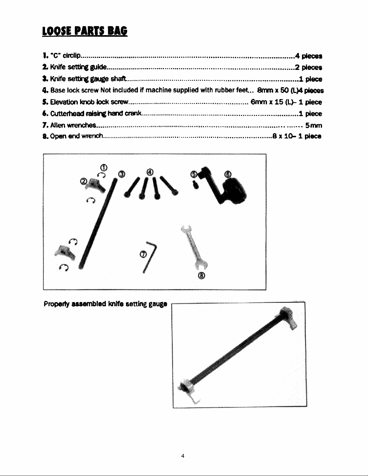
LOOSE
PARD
IIG
I. ·c·
11<rlife
cI..
4.
S.
circUp
set'tir\I:
t<rUfe
settir'C
Base
lock
EJevation
...............................................................................................
... Ide ............................... , ....•........ ····•········.·· ........... 0
&ace
screw
knob
Not included
lock
6. Cuttertleacll'8islrC,
7. AI'efl
L
Oper1
~
erM:I
...................................................... +
Wl'ef"dl
.......
staaft..
screw
t1alcI
r.+
'F
....................
.......................
............................................................................................... 1
if
machine
... -............................................................
CI'1IIlk.
......................................................................................
••••••••••••••••••••
supptied
~
•••••••
with
...................................................
+
••••••••••••••••••••••••••••••••••••••••••••
rubber
feet ..
8rrYn
6rnrn
x 50 (L)4 pieces
x
15
(L)-
8 x 1.0- 1 piece
4
pieces
2
pI~
piece
1 piece
1
,:Mace
SI'I"II'n
4
Page 7

MOUNTING
1.
When
2..
Choose
3.
Ule pi
two pieces of lumber. This
t\YO
planer onto
Use 1he four
base
onto
I,HE
....
ts not
pieces
the
wood surface.
M8
x
SOmm
the
wood.
of
PLANER
mounted
will
WCXJd
eccordng
long
ONTO
on 8 planer stand.
ensure maximum stability .
heJtaIon8
to
the
siZes
socket
THE
it
sho\vn
head
WOOD
suggested lIlat it be mounted onto
screws
on
1he
(finished)
BASE
figure below, Mount the
to
mount
the
....
r 1
D
plane
5
Page 8
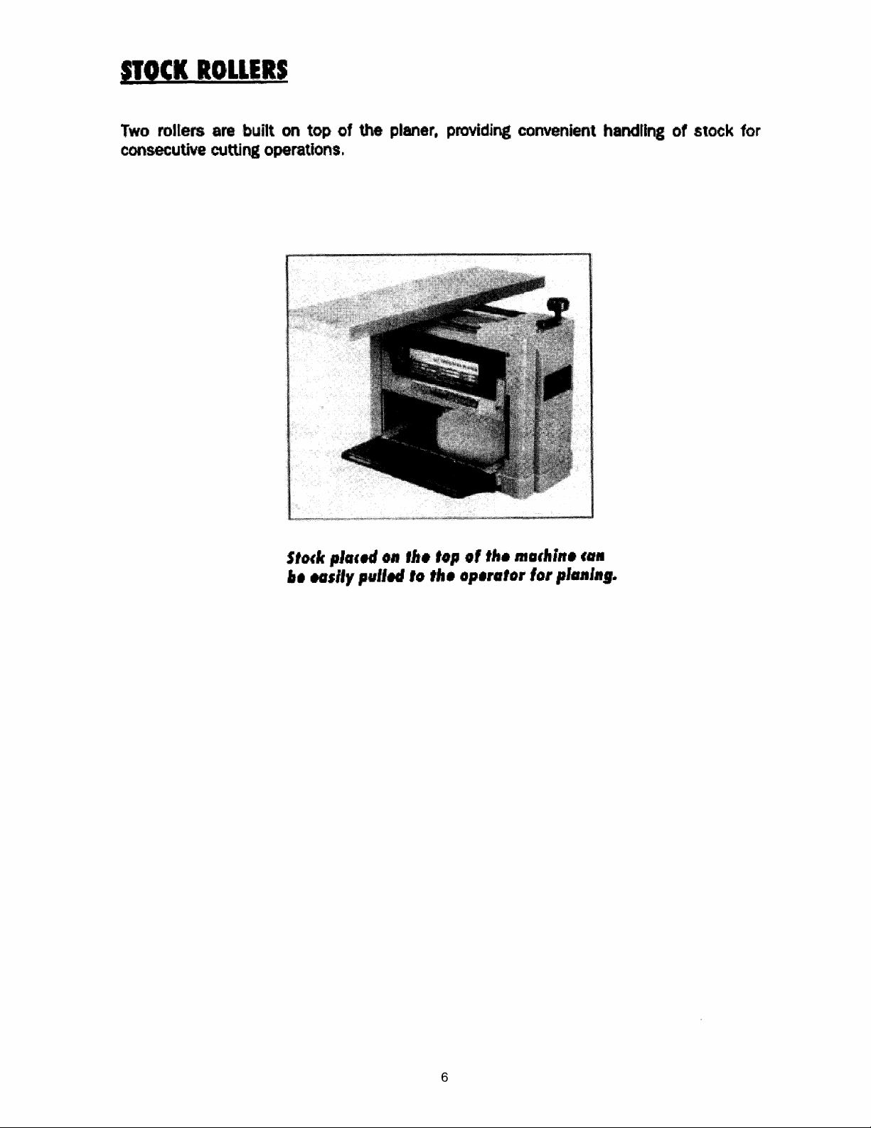
'lOCK
Two
consecutive
ROLLERS
rollers are built on
cutting operations.
top
of
the planer, providing convenient
handUng
of
stock for
SIod(
••
H.lly
pla,..I
011
pulled 10 ,11.
Ii,.
'.,1
0'
,It.
,.,.,.'or
madillne
for plall''',.
fall
6
Page 9

Motor:
Volts •••••••••••••••••••••••.••.••.••.•.•.•..•........••••.•.•••.•.••••••.•••. 220V
160Hz
Cvttl8, capacity:
Lengttl of stock (min) ...................................................................................... 5" (127mm)
Widtl1
Thickness
DepUl
Feed
of
stock (max) ...............................................................................
of
stock. .........................................................................
of
cut (max.) ...........••..•.••••
o.
•••
••••
................
•••••
...............
•••••••
0.2
•••••
rate ...........................................................................................
12-1/2·
..
-6-
••••••
26.2
(5
••••
fPM
(318mmJ
....
153mm)
2.5
mm
(8m/min)
Number of
Diameter ....................................................................................................
Idle
ruMing
knives.....
.••.•..
•..
....... ....................... .•.•... ........ .... .••......
••.
.......... 2.5lngJe
1.89·
speed .............................................................................................
9000
Cuts per minute .....................................................................................................
O
••
rall
dI
...
nsI08s:
LengUl
WidU1
Hci~lt
Net weigl1t ..............................................................................................
Gross weight ................................................................................ , .............
Packing size
......................................................................................................
22.8·
..........................................................................................................
......................................................................................................
(L
x W x
H)
.......................................................................
18.2·
67.6Ibs
70lbs
24· x 18.3· x 13.8"
22·
(58Omm)
(558mm)
(463rnfJl)
(30.7kg)
(31.8ke)
edged
(48n1m)
RPM
16000
7
Page 10

.VIII
the
planar can
extenIianI
THE
be
befcn
PUNER
moved
you
by
move
canylng
the
planer •
it
on
the right
and
left
of
the
frame. Qose the table
•
".1..
&fake
and
unplUUecJ
sute
the
plane
before
has
you
been
move
tum«l
the
8
oft
Planer
..
Page 11

ON/OFF
Your
planer
use.
If
yoU intend to be
chance
the
OFf position. Store
planer on, insen the
then
be
SWITCH
has a nx:ker style switch with a removable locklng
of
its
use
by
operable. To
away
from the machine
others, especially children, remove
it
in a
saf'e.
inconspicuous place in your workshop.
red
locking key and
tum
the
ptaner off, tum the switch
tum
for
a long period
the switch
the
to
to
locking
the
the
key
to prevent unauthorized
of
ON
OFF
time and
key
position.
positron.
there
with
the
To
The planer will
is
any
switch in
tum
the
SAFETY
SWITCH
WARNINGt
CIRCUIT
The
machine is
the sWltch
ON/OFF
Always be sure the switch is in
before connecting the planer to
BREAKER
win
pop out.
provided
tile
OfF
position
the
power source.
5WI,TCH
WlUl a breaker switch fur ovartoad protection. If an overtoad occurs.
tr
O.is
happens. walt sevC'ral rr
..
nutes.
and
press
the switch
to
reset.
BREAKER
SWITCH
9
Page 12
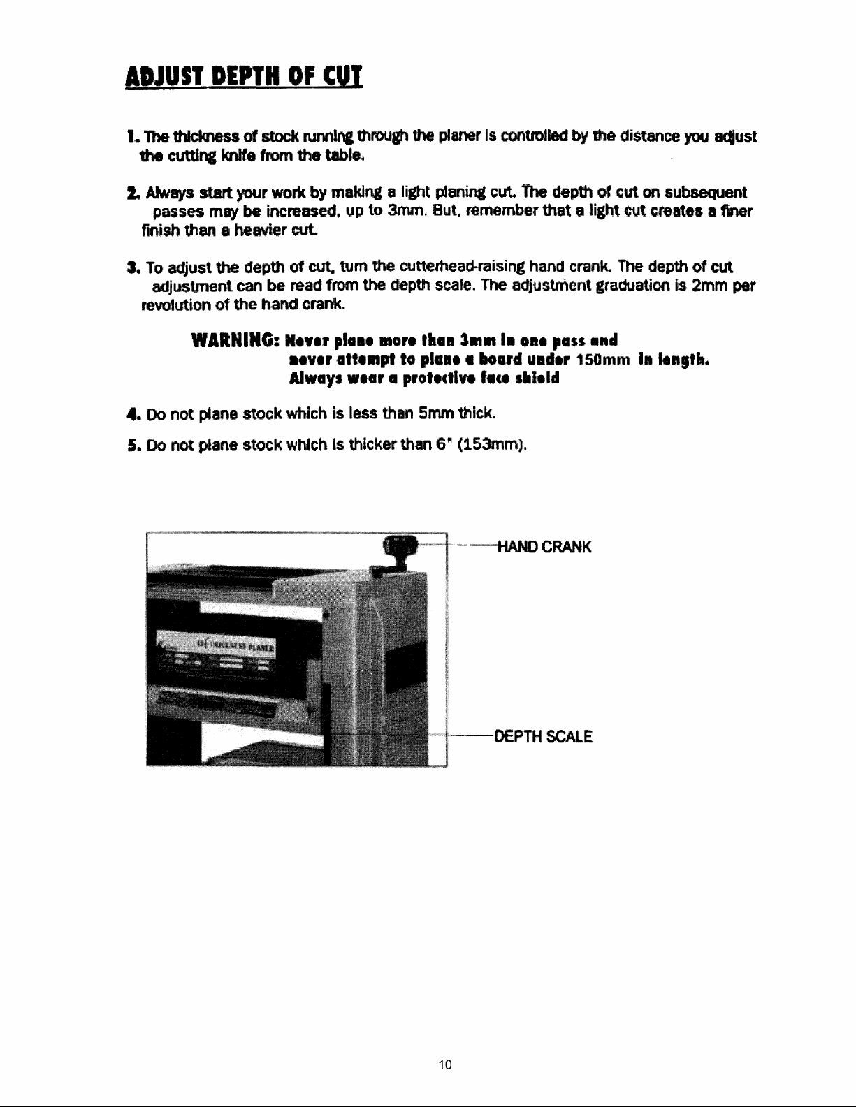
ADJUST
1.
The thickness of
the
cutting knife from
2.
Always
passes
finish then 8 heavier cut.
3.
To
adjust
adjustment can
revolution
DEPTH
stock
start
your work by making 8 light planing cut.
may
be increased.
the
depth of cut. rum
be
of
the
hand
OF
CUT
ruMIn&
the
read from the depth scale. The adjustment graduation
Crank4
through
tabl14
up
the
plener
to
3mm. But, remember that .. light cut creates a tiner
the
cuttemead-rajsing
Is
contmIled
The
hand
by
dep1h
crank.
lhe
distance
of
cut on subsequent
The
depth of cut
you
is,
adjust
2mm
per
4.00
5.
Do
WARNING:
not
plane stock which is less than
not
plane
stock
N.WII
••
vlr
Alway.
which
pla.1
att
wI.r
Is thicker than
.ort
...
pllo
.h
pla.l.
a protlctlve I.c
,5mm
••
31ft
II
Hard
thick.
6~
(153mm).
-~-HANO
I,
•••
0
••
uld.r
I.ld
CRANK
SCAlE
pass
150mm
and
I"'
••
gt".
10
Page 13
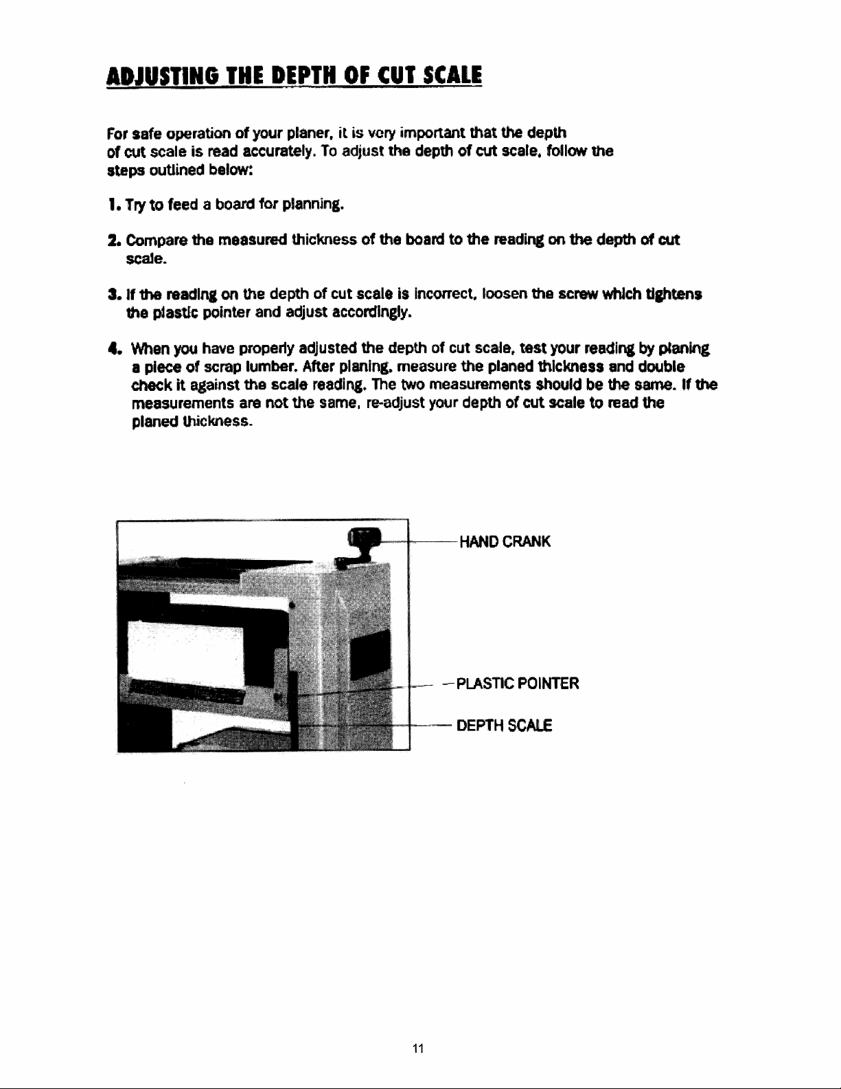
ADJUSTING
For
safe
operation
of
cut
scale
steps
2.
DutUned
I.
Try
to
Compare
feed a board
THE
of
is
read accurately.
below:
the
measured
scaJe.
3.
If
the
read1n&
the
p4astlc
4.
When
you
a piece of
Check
measurements are not
it
planed
on
the
pointer
have properly adjusted the depth
scrap
lumber.
against
the scale
U'tickness.
DEPT"
your
planer.
for
planning.
thickness
depth
and
adjust
After
the
OF
it
is
To
adjust
of
of
cut
scale is Incorrect. loosen
accordingly.
planing.
reading.
same.
CUT
very
the
The
re-adjust your depth
SCALE
important
the
depth
board
of
measure
two
measurements should be the same.
of
to
cut
the
that
cut
the
reading
scale.
planed
the depth
scare.
the
test
follow
on
the
screw
your
readina
thickness
of
cut scale to read
the
depth
whJch
and
of
cut
tllhtens
by
planing
double
the
If
the
I---~-
HAND
~
PLASTIC
CRANK
POINTER
11
Page 14

REMOVING
IHE
PLANEIINIVES,
WIIIIIICh
1.
Remove
Unplu,
belonJ
the chip
your
removing
guard
2. loosen the lock bar
are
spring loaded,
I.
Take
out
the
knife (e).
planer from
the
by
removing
(B)
and
and
will
and
the
power
planer
knife by tuming the lock screws
push
then
out
'the
knives.
the
Vlhcn
knife
source
screws
Ute
rock
SCREWS
CHIP
shown in figure.
assembty is loosened.
bar (9).
GUARD
fA)
clockWise.
The
knives
SCREW
12
Page 15

I_DALLING
THE
PLANER
KNIVES
Willi
1.
2.
3.
••
Remove
fit
the
At 1he knife
tumirC
direction
..
Set the knife
heit)lt
..
Be
sure 10 replace
Unplug your plan.r from Its
betote
1he
knife
the
must
I8mot11n1
Knives
lock bar (B)lnto the slot on the cutterhead.
Iota
screws
(See
be
accordlng to
th8
fig. below)
hel,&hts
reaet
the
or
slat
on
counterclockwise.
according to the Instructions
every
time
Chip
gu8ICI
power
InstaIll,."
the
th4t
the
the
Instructions,
euttemead, and tighten the Iockbar-kntfe
knlvel
after
source
planer kniwl
Make
sure the knife is facing
ant
taken out for
knives are
••
for
............
on
the following page.
any
instaUect
PIII
the
reason
..
r 1.1
as.setrmly
correct
The
•
...
knife
-.
by
WHIII...
Will
....
o
The
knife
edge
Is vel)' susceptible to chipping"
UN
caution when handling UHI'BUge
knIwIs
The
to
to
avoid
assembly
pre""
Clama,lltl
must
8Cddents
them.
be tlptened
dud",
securely
planing.
near
A
the
13
Page 16
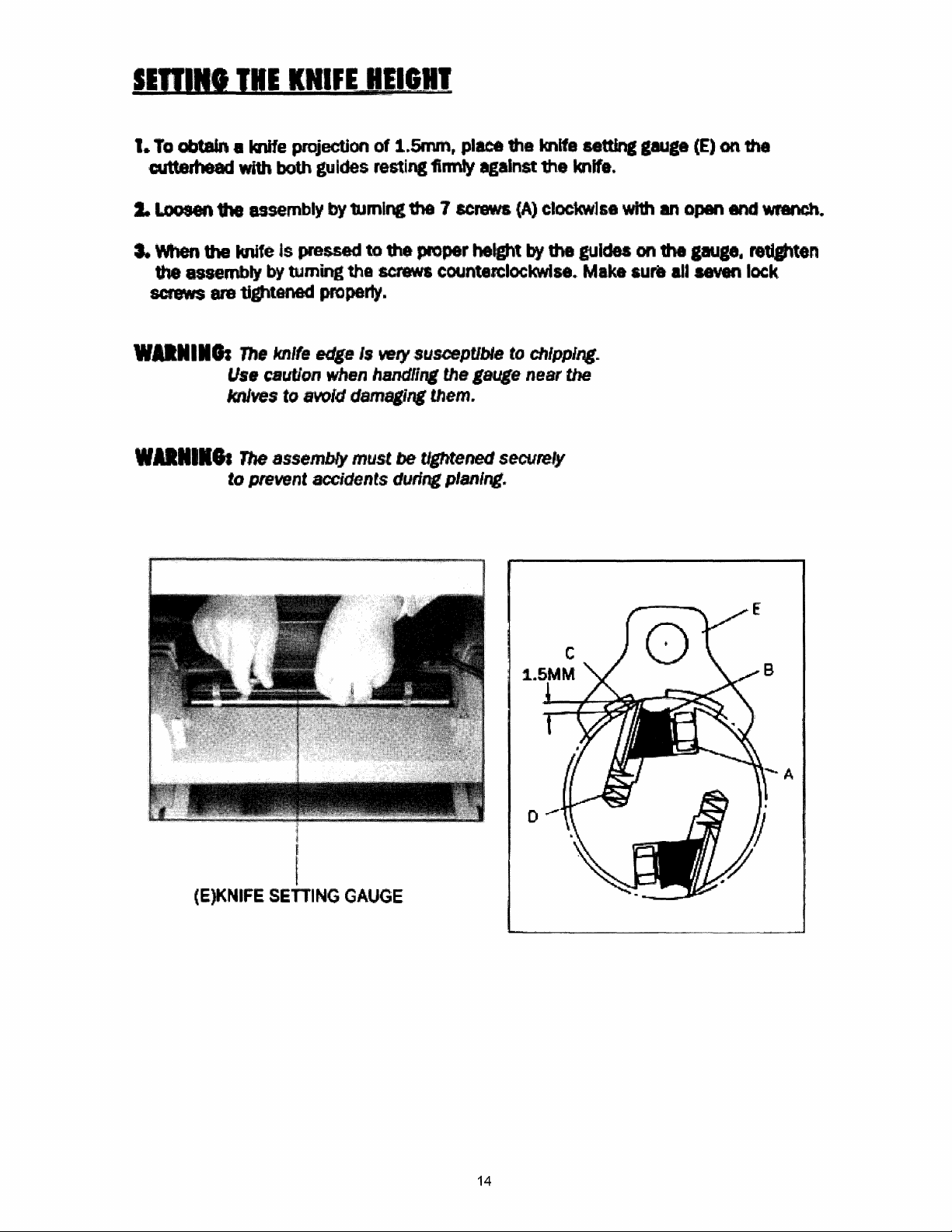
SEUIN'
1.
Ta
abtaIn.
cutterhead with both guides resting firmly
I.
Loosen the assembly by
a.
\\'hen
the assembly by tuming the
screws
THE
the
knife is pre,ued to
are
tightanad
KNIFE
knife projection
HEIGHI
of
1Umlng
screws
property.
1.5I'run. place the knife setting
the
the
proper height
against
7 screws
counterclockwise
the knife.
(A)
clockwlse with
by
the guides
..
Make
gauga
an
on
aura
(E)
open end
the
gauge.
all seven
on
1he
re1Wtten
lock
WNnCh..
WDIIIIII
WAIIIIe.
The
knife
edge
Is
wlf
susceptible
Us.
cauUon
knJves
The
assembly
to prevent accidents during planing.
to
when
svoid
handli", the lauge
damaging
must
them.
be
tightened
to
chipping.
near
securely
the
A
(E)KNIFE
SETTING
GAUGE
14
Page 17

1. The table extensions
are
mounted
at
the fronl and rear
ends
of
the main table.
2. Raise
the
cuttemead
assembly
so
that
adjusting the extensions.
3.
4.
Place
If
a straIght edge across the main table
1he
main
table and
table
extension
extension by loosening nut (8) and turning
touches the straight edge.
Adjust
the right
way.
5.
The roller
further adjustment.
has
been
factory
set
to
angn
you
can
get a clear view and work comfortably
and
table extension to
mller
are
not aligned. then adjust the table
screw
and
(A)
until the table extension
left s ide
of
with Ule table extension
be
adjusted
..
just
the table extension in this
and
t
,·equires
no
TABLE
EXTENSION
ROLLER
NUT(B)
SCREW(A)
15
Page 18

UKI"G
THE
CUllERHEAD
AND
WORKTABLE
PARALlEL
Plane
not
Adjust the cutter shaft
The
gauge
following
8 workptece and
the
same
tools used for checking
block
on
both sides of
accorcnng
procedures.
measure
and
the
are
to
the
figure
the
workpiece
the
workpiece.
worktable
shown
below.
shown
thickness after the cut.
perfonn the
so
they are parallel.
Please
size.
Make
use
the adjustment
following.
hardwood
If
the thickness
to
make a
as
per
is
toot
Ule
16
Page 19

JAIliNG
I.
Undemea1h
2.
Disengage the bevel
3.
Tum
tum counterclockwise
the
THE
the
bevel
CUlfERHEAD
main table. loosen
..
ar
next
to
gear to adjust the Mtght of that side of the cuttarheed.
lives
O.12mm
the
the
AND
·e· circllp
elrcllp.
raising
WORKtABLE
as
shown
See
f.gure 2 below.
thickness.
PAULLEL
in flIure 1
below+
One
tooth
of
4. After adjustment,
"C·circlip
re-engage
the
bfwal.,ar
and replace thII
·C·
clrcllp.
17
Page 20

PLIN'N'
FOR
FINISH
Planing
cuts on 1he board.
achieve a
AMaya feed 1he board in a direction
this
Tom
cause
for
• smooth finIsh
However.
arnoo1h
aids 1he knife in
fibers
gjve a fuzzy
your
knife
finish.
to
lift
IS
several other things are important besidea
severing
appearance
large
chips
well as thiclaless Is best
the
from
appearance.
JlleKNESS
Thickness
c.reating.
The
art
about
width of
direction
~anln&
a smooth surface parallel to the opposite side
of
thick.ni!ss planing consIsts mainly of using
the
deDth
the
and
PLANING
Is the
of
stock. but the
grain structure. .
cut
sizing
in
various
hardness
of
mate.rial
slWatJons,.
1hat
allows
wood
fibers rather than lifting
to
the
the board's surface.
the
surface.
planer blades
Feeding against the
to a deslred thickness. while
You
must
of the
board,
its dampness. straightness.
accomplished
CBUslnl
of
the board.
good
judgment
take
,nto account not
by
taking light
Ilaht
cuts to
to
cut
with
the
.-.d
tearifC the fibers.
pn
can
a
very
unsf&htIY
only
pin
grain
afso
the
..
Tha affects of these factors upon the quality
be
...
mad
1hrotJgh
with •
cuts
FOR
ff more materlar needs to be
than 3mm
thickness has
new
type
on
scrap material If possible prior to
ADDITIONAL
met
exPerience.
of
wood,
or
It is
always
one with unusual problema. to make
advisable.
working
PLANING
removed,
complete another pass. Repeat this process until
been reached.
hand crank
of
'the finished
on
the
work
whenever
your
cuttemead
working
finished product
can only
test
no
mora
the
desired
18
Page 21

LUBRICATION
1.
The recommended lubrication
operation
dust.
dkectly
tends
the
chain. This hastens
din
on
to
IS
to
simply
or
WOQd.shavings~
the
chain.
hasten
the
collection
Wipe
the chain clean.
coat chain
Over..ailing
WI
I'
speed reduction and height adjustment
2.
The
bearings on the cutterhead
further attention.
for
roller chains used in memum
defeats the purpose
of
dust, shavings. etc., and works
and
leads to premature
are
When
with
8 light film
,chains,
factory
there
of
of
replacement.
as well
as
1ubricated
to
slow speed
is
an appreciable bulld-up
oil
but
naver
the
rubrication. since
'them
'the
elevation screws.
end sealed.
pour
into members
This
applies
They
require
the oil
it
simply
to
of
of
the
no
PERIODIC
Bulldup
Periodic
of
cleaning is not
MAINTENANCE
sawdust and other debris can cause your machine to
p1anlna·
1.
Close-fittina
be
cleaned with a
replaced
2.
Remove
flammable
parts, such as thelockbars and
in
their
,.sln
solvent
only
rec1ommended.
brush
respective positions, slightly dampened with oil.
and
and
freed
other accumulations
fr'om
but
mandatory
the
clinging
from
feed rolls
for
accurate
planer cuttemead slots should
foreign
matter
and
labile with a
plane
and
inaccurately.
precision
then
n0n-
19
Page 22

'RoualISHOOTING
PIOBU.
FUZZY
TORN
GRAIN
GRAIN
'OS51IU
1..
PlaninI
moJsture
2.
Dull
I.
Too
2.
Knives
grain.
3.
Dull
CAUSE
wood
with high
content.
knives.
:'
he8\'Y
a cut
cutting against
knives.
the
IOUDY
I.
Dry
the
WOOd.
2.
Sharpen
1. Review proper depth
ofc~
.2.
Feed
Brain,
workpiece
3.
Sharpen
knlves~
wood
with
or tum
Bround.
kniVes.
1tIe
I
ROUGH/RAISED
GRAIN
1.
Dull
knives
2.
TOO
heavy
3.
Moisture content too
4.
Cuttemead
a cut.
bearings
damaged.
high.
I.
Sharpen mlvas.
t.
Review
of cut.
3.
Dry
4.
RePlace
proper
the wood.
bearings
depth
20
Page 23

TROUBLESHOOTING
PlOIUM
POOR
WORI<PIECE
FEEDING
LUMBER
JAMMED
OF
POS'SIIU
I.
Planer table
2. Feed roller dam8led
CAUSE
dirty,
3. Sprocket dam8led.
4.
Gear
box
malfunction.
1.lnadeQ1J8te
height.
knife
setting
IDIEDI
1.
C1ean
residue. and lubricate
planer table.
2.
Replace.
3.
Repface.
4.
Check lear box.
Set
1.
COlTeCt
off pitch
the
kr'INes
height.
to
and
the
21
Page 24

'ROUBlESIOOTING
PIOIUM
UNEVEN
CUT
BOARD
OOESNtT
DEPTH
CHAIN
MECHANICAL/
~
ELEcmlCAL
WON'T
DEPTH
$IDE
TO
SIDE
THICKNESS
MATCH
OF
CUT
SCALE
JUMPING
MACHINE
OF
START/RESTART
'OSSIIU
CIUSE
1. Knife projection not unifonn.
2. Cutterhead
planer
Depth
I
2. Sprockets wom.
1. Not
of
..
Sprockets misaligned.
ptuggad
not
levelled to
bed. table;
cut
scare
incorrect
In.
2. Circuit breaker/fUse.
3.
Motor
4.
Loose
5. Overload reset
failu,re.
wire.
I'las
not
reset.
IUIIDY
1.
Adju~
2. Level cutterhead
Adjust depth
I.
Align
2.
Replace sprockets.
1. Check power source.
2.
Check power
2.
Have
4.
Have
qualified electrician.
5.
Allow
down and restart.
knife proJection.
to
Df
cut
scale.
sprockets.
source~
motaf
motor
machine
cheeked.
checked by
to
c~
I
I
REPEATED
mlPPING
IN
MOTOR
RESULTING
STOPPAGE
CtRCUIT
6.
Motor
staner failure.
1. Extension cord too long
too thin.
2.
Knives too
3.
low
vo~tace
duU.
n.lMing. 3. Check voltage.
22
or
6.
Have
checked
electrician.
1.
Use
extension
2.
Sharpen
knives.
motor
starter
by
qualified
a shorter or thicker
corel.,
or
replace
I
Page 25
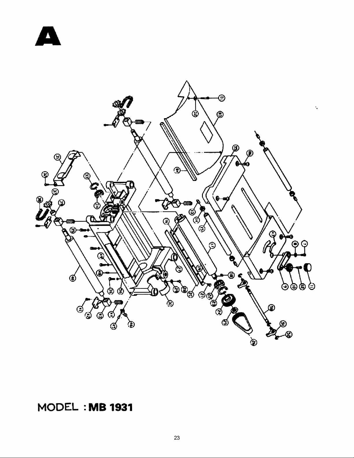
A
MODEL
:
MB
1931
23
Page 26

PARTS
liST
A
D
••
No.
1
2
3
4
5
6
7
8
crlptlon Speciftcatioft
Upper
Hexagonal
Spring
Chip
Chip guard
wamlng label 1
Sponge piece
Upper
Hexagonal
HexagonaJ
Spring
Mechanism
socket head
washer
guard
assembly
guard
socket
socket head
washer
head
screw
screw·
screw
MS40"SP*30
5.1-9.2·1.3
M8·1.2"·16
MS·l.0P·16
8.1·10.2*1.4
Hand'. set
9
10
11
12
Handle
Hand knob
Handle
Handle
crank
gu
ard
shaft
Quantity
2
2
1
1
1
1
4
1
1
1
1
1
1
1
13
14
15
16
17
18
19
20
21
22
23
24
25
26
27
Spring pin
Bush
RoUer
Glb
Cutterhead
Double
Spring
Knife
Gib
Bearing
·C·
Cunemead
Nut
Belt 135-J6
Upper
round
lock screw
clrcllp
pulley
frame
end
key
S-20
5·5*10
1/4-28UNF
6203-2NK
RlW-40
4
2
1
2
1
1
1
'2
14
1
1
1
1
1
1
I
24
Page 27

A
Cross
28
Plain washer
29
Pulley
30
Chain
31
Cross
32
33
34
35
36
37
38
39
40
41
42
43
round
head
screw
M4·0.7P*S
4"10·0.8
guard
guard
round
lie·
ctrclip
Bearing
Hexagonal socket head screw MS-1.OP·20
Self tappina
Chain sprocket
Chain
Spacing collar
Rubber
Cross
Bracket
Roller bracket
roller
round
p1ate
head
screw
head
screw
screw
M5·0~8P·8
I
RTW·35
6202-2NK
M8·1.59P*2Q
'41-26P
M5*O.8p·l0
2
2
1
1
2
1
1
2
:2
3
2
1
2
8
4
4
Bracket spring
44-
Cross
45
Indicator 1
46
Indication label
41
Pin
48
49
Spring
Gauge
50
Knife setting guide
51
-E- circlip
52
Waming label 1
56
round
washer
rod
head
screw
M4·0.7p·S
6.1·10.2*1.4
ETW,,9
4
,1
1
2
4
1
2
4
I
25
Page 28
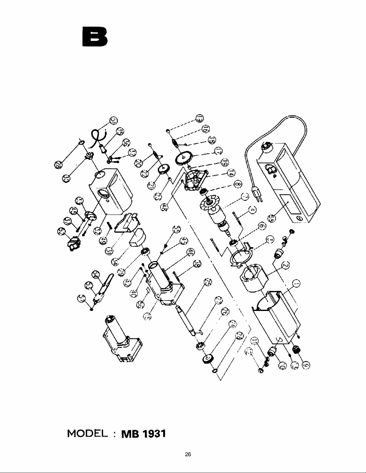
B
MODEL:
MB
1931
26
Page 29

PARTS
LIST
B
No.
1
1"'---"
2
3
4
·6
7
8
9
10
10
11
13
14
Description SpecIfication
Motor
Motor casing
Assembly
Stator assembly
Plate
Self
tapping screw
Bearing
Rotor
assembly
Bearing
Motor pulley
,
Carbon
Carbon
Carbon
Carbon brush
Set
Gear
brush 2
brush
bru
sh
screw
box
cover
bracket
cover
M4.8S·1.S9p·70
'6201·2NK
-
M~.8P·l0
Quantity
1
1
1
2
1
1
1
1
1
1
2
2
1
15
16
17
18
19
20
21
22
23
24
Gear
box
Gear
shaft
Gear
Double
Bronze
Gear
round
bush
shaft
Gear
Double round
Bush
Gear
end
end
key
key
8 1
70
4·4·8
8·11.13·10
8
46
343
.•
7
6-10*9
33
-
,1
2
25 Shaft 1
Bearing
26
Ooub~le
27
28
29
·e· cirelip
Bearing
round
end
key
'6202Z(A)
4*4·10
STW-15
116002Z,(A)
1
1
1
1
1
2
1
1
1
2
1
,
-
27
Page 30

B
30
31
134
32
36
i Self tapping
37
49
35
51
33
38
40
42
45
46
Chain
SwUch
SpacIng
Oust guard
Switch
Electrical wire
R type plug
Power
Safety wire ball
PowC!r
Switch
Self
sprocket
casqassembly
plate
guard (black) 1
wires
wi
res
plate 1
tappIn, screw
Plain
washer
Cross
Teeth
SeJf
round
washer
tapping screw
plug
screw
he,ad
clamp
screw
8
M4·16
SSP-1O
M4.85-1.59P* 50
4*10·0.8
M4*O.7P*S
BW-S
M4.8S·1.59P*SO
1
1
1
1
1
4
1
'1
,1
1
3
2
2
3
1
I
--
48
PositionIng pin
Safety swltch
52
53
Temperatu
57
Nut
54
Temperature control wire
55
Cross round head
MotOf label
56
58
MotO'f
re
name plate
contrQ~
switch
s~rew
-
5.6-7.1*5
2.0/1C·13em*2
MS·.OSP*S
2
1
1
1
1
1
1
1
1
28
Page 31

(2)
__
--;1--(*)
MODEL:
MB
1931
29
Page 32

PARTS
LIST
c
No.
1
2
3
4
5
16
1
18
9
10
11
12
13
14
DescrlptJon
Base
Assembly
Left
screw
Double round end
Bevel
gear
"E"
circlip
Double
Hexagonaf socket head
Axing
Transmission
Table extension bracket
Plain
Table extension bracket
T able extension roll
Depth scale
Hexagonal
round
piece
washer
head
end
shaft
er
screw
key
key
(seamless
screw
~
stee4
pipe)
, SpecEticatlon
4*4·8
ETW..a
4·4*8
MS*1.0P*10 4
6·19·3
M6*1.0P-S
20*350
MS·1.0P*25
Quantity
1
1
2
2
2
2
1
4
4
4
2
1
4
15
16
11
18
~
19
20
21
22
23
24
125
26
~'
27
128
Nut
Table
extension
Base
Plain washer
Hexagonal
Spring
Pad
Cross round
Guide plate
pin
Column
Double round
Right
-
' Hexagonal
screw
Fixing piece
socket
head
end
socket
head
screw
screw
key
head screw
Me·1.0P
5/16*23·2
MS IiIl.25P
0*20
~
~
M6·1.0P*10
4·4·8
MS*1.0p·l0
iii
20
4
2
1
4
4
4
1
4
2
4
1
1
4
2
30
Page 33

c
Bevel
29
·S"
30
Side guard
31
gear
clrcllp
S'fW.10
2
2
7
32
33
34
35
36
Cross
Bush
Screw
Carrying
Cross
round tlead
CAl
spring
round
handle
head
screw
screw
M5*O.SP*6 4
4
2
2
8
31
 Loading...