

Page 1
X824-05-02
MATRIX 66
SUPER-HIGH-DENSITY VIDEO SWITCHING
SYSTEM
Copyright © 2005 Vicon Industries Inc. All rights reserved.
Product specifications subject to change without notice.
Vicon and its logo are registered trademarks of Vicon Industries Inc.
Vicon part no. 8006-8824-05-02 Rev 307 Section 2
Warning: To reduce a risk of fire or electric shock, do not expose this product to rain or moisture.
VICON INDUSTRIES INC., 89 ARKAY DRIVE, HAUPPAUGE, NEW YORK 11788
TEL: 631-952-CCTV (2288) FAX: 631-951-CCTV (2288) TOLL FREE: 800-645-9116
24-Hour Technical Support: 800-34-VICON (800-348-4266)
UK: 44/(0) 1489-566300 WEB: www.vicon-cctv.com
Page 2

Page 3

pl
eh
Page 4

Page 5
FCC Notice
Note: Complies with Federal Communications Commission Rules & Regulations Part 15, Subpart B for a
Class A digital device.
WARNING
This equipment generates and uses radio frequency energy and if not installed and used properly, that is, in
strict accordance with the manufacturer’s instruction, may cause interference to radio and television
reception. It has been type tested and found to comply with the limits for a Class A computing device in
accordance with the specification in subpart B of part 15 of the FCC rules, which are designed to provide
reasonable protection against such interference in a commercial installation. However, there is no guarantee
that interference will not occur in a particular installation. If this equipment does cause interference to radio
and television reception, which can be determined by turning equipment off and on, the user is encouraged to
try and correct the interference by one or more of the following measures:
• Reorient the receiving antenna.
• Relocate the equipment with respect to the receiver.
• Relocate the equipment away from the receiver.
• Plug the equipment into a different electrical outlet so that the equipment and receiver
are on different branch circuits.
If necessary, the user should consult the dealer or an experienced radio/television technician for additional
suggestions.
The user may find the following booklet prepared by the Federal Communications Commission helpful:
“Interference Handbook, Bulletin CIB-2”
This booklet is available from the U.S. Government Printing Office, Superintendent of Documents, Mailstop
SSOP, Washington, D.C. 20402-9328, ISBN 0-16-045542-1.
Warning: Power must be removed from this unit before removing circuit modules or ribbon cables.
Caution: This unit contains circuit cards with integrated circuit devices that can be damaged by static
discharge. Take all necessary precautions to prevent static discharge
Page 6

Page 7
Important
Safeguards
GRAPHIC SYMBOL EXPLANATION
The lightening bolt symbol alerts the user to the presence of
dangerous voltage that may present the risk of electric shock.
The exclamation point symbol alerts the user to the presence of
important operating and maintenance instructions.
1. Read Instructions - Read all safety and operating
instructions before the product is operated.
2. Retain Instructions - Retain all safety and operating
instructions for future reference.
3. Heed Warnings - Pay attention to all product warnings.
4. Follow Instructions - Follow all operating instructions.
5. Cleaning -(Do not use caustic, abrasive or aerosol
cleaners)
a) For units that CAN BE DISCONNECTED from the power
source, use a damp cloth for cleaning.
units that CANNOT BE DISCONNECTED from the
b) For
power source, use a damp cloth for cleaning and do not
allow moisture or liquids to enter vents.
6. Attachments - Use only UL Listed Vicon recommended
attachments to prevent unit damage and personal injury.
7. Water and Moisture - Use only products designed for
outdoor environments where they will be exposed to water or
moisture.
8. Accessories - Do not place the unit on an unstable surface
to a vo id f al li ng . Use only UL Listed Vicon recommended mounting
accessories.
9. Ventilation - Do not block ventilating slots and openings as
they ensure reliable operation. Do not place the unit near a
heat source or into an enclosure unless recommended by
Vicon.
10. Power Sources - The product should only be operated
from the recommended power source. Use only a UL Class 2
indoor/dry or Class 3 outdoor/wet power supply.
11. Grounding - Only products equipped with a 3-prong
grounded plug should be inserted into a grounded power outlet.
Contact an electrician to replace an obsolete outlet. Do not
force a plug into a non-grounded outlet.
12. Power Cord Protection - Power supply cords should not
be routed in trafficked areas or in tight spaces where they will
be pinched or used to bear weight. Allow some slack in the
cord where it enters the unit.
13. Outdoor Cable Grounding - Use only grounded outdoor
cables to protect against voltage surges and static charges.
Section 810 of the National Electrical Code, ANSI/NFPA 70-
1984, provides information on proper grounding of the lead-in
wire to an antenna discharge unit, size of grounding conductors
and the requirements of grounding electrodes.
14. Lightning - Disconnect the product from its power source
and cable system when possible to prevent damage due to
lightning and power-line surges.
15. Power Lines - Do not locate outside cables over power or
utility lines where they can fall and make direct contact. Contact
with power lines can be fatal.
16. Overloading - Do not overload wall outlets and extension
cords to prevent risk of fire and electric shock.
17. Object and Liquid Entry - Never probe through, or spill
liquid into, enclosure openings to prevent risk of fire or electric
shock.
18. Servicing - Refer all servicing to qualified service
personnel.
19. Damage Requiring Service - Obtain service when:
a) The power-supply cord or plug is damaged.
b) Objects have fallen or liquid has been spilled into the
product.
c) The product is not designed for outdoor use and has been
exposed to water or moisture.
d) The product does not operate per the operating
instructions. Perform Vicon recommended adjustments,
modifications and troubleshooting only to avoid unit
damage and personal injury.
e) The product has been dropped.
f) The product shows a significant change in performance.
20. Replacement Parts - Use only Vicon specified
replacement parts or an approved equivalent to prevent unit
damage and injury.
21. Safety Check - Request safety checks to be performed
following repair or maintenance to verify proper operation.
22. ESD Precaution - Take all normal electrostatic discharge
precautions to avoid component damage during installation and
operation.
23. For 230 VAC Devices Only - When the disconnect device
is not incorporated in the equipment or when the plug on the
power supply is intended to serve as the disconnect device,
follow the guidelines below:
a) For permanently connected 230 VAC units, a readily
accessible disconnect device must be incorporated into
the site wiring.
b) For 230 VAC units with a plug, the outlet must be installed
near the unit and be easily accessible.
X824-05-02 Rev 307 Matrix 66 Important Safeguards • i
Page 8

Page 9

Contents
Quick Start..........................................................................................................................iv
Introduction .........................................................................................................................1
Preparation ..........................................................................................................................5
Installing the Matrix 66 in a Rack..................................................................................................................5
Tools Required ...............................................................................................................................................5
Supplied Accessories....................................................................................................................................6
Camera and Monitor Connections.....................................................................................7
Cameras ..........................................................................................................................................................7
Monitors ..........................................................................................................................................................8
Single Card Cage Installation...........................................................................................10
128 Cameras, 32 Monitors...........................................................................................................................10
Multiple Card Cage Installation........................................................................................12
Looping Camera Video ................................................................................................................................12
Camera Expansion Using Serial Loop .......................................................................................................14
Large System Examples..............................................................................................................................15
Looping Control Signals..............................................................................................................................18
Expanding an Existing System........................................................................................20
Adding Cameras...........................................................................................................................................20
Adding Monitors...........................................................................................................................................21
Camera and Monitor Addressing................................................................................................................21
Adding a VI466A CPU Card.........................................................................................................................28
Adding a VI466A Titler Card........................................................................................................................30
External Control System Connections............................................................................32
Keypad and Receiver Connections .................................................................................34
Remote Keypads ..........................................................................................................................................34
Programming Keyboard...............................................................................................................................35
Receivers.......................................................................................................................................................35
Alarm and Alarm Printer Connections ............................................................................37
Alarm Interfaces ...........................................................................................................................................37
Alarm Printer.................................................................................................................................................37
Host Computer Connections............................................................................................39
Miscellaneous Device Connections.................................................................................41
Using the V66RCB Cable.............................................................................................................................41
Using the Loop Out Connector...................................................................................................................41
Power Connections...........................................................................................................42
Maintenance ......................................................................................................................43
Fuse Replacement........................................................................................................................................43
Storage ..........................................................................................................................................................43
Reference...........................................................................................................................44
Cable Recommendations ............................................................................................................................44
Twisted-Pair Cable .......................................................................................................................................46
Daisy-Chain and Star Configurations ........................................................................................................46
Assembling D-Shell Connectors.................................................................................................................47
Technical Information.......................................................................................................49
Vicon Standard Equipment Warranty....................................Error! Bookmark not defined.
X824-05-02 Rev 307 Matrix 66 Contents • iii
Page 10
Quick Start
All safety instructions should be carefully reviewed before using the Quick Start guide. This guide is intended for a quick overview of
product installation. You must refer to the manual for detailed and important information such as cable recommendations, sample system
connections and DIP switch settings.
1. Camera and monitor panels on the rear of the Matrix 66 are labeled. Connect cameras and monitors to your system using the
numbered labels as a guide. Terminate the appropriate BNC, D-shell connectors or switcher board shunts (JP1-JP64); do not
“double terminate.”
2. Connect the supplied cable from Alarm/Control In of the first card cage to the appropriate connector in the table. The “Monitors”
column indicates the hardware address of the monitors that will be switched at the specified connector. Refer to the figures that
follow.
Monitor Panel Camera Panel
Control System Connector Monitors
V1500 Control 1 on V1500CDU-VID (or V1500CDU-HSB-VID) 1-64
V1500 Control 2 on V1500CDU-VID (or V1500CDU-HSB-VID) 65-128
V1300 J2 on V1300X-VC-S (or –F) 1-128
V1300 J3 on V1300X-VC-S (or –F) 129-256
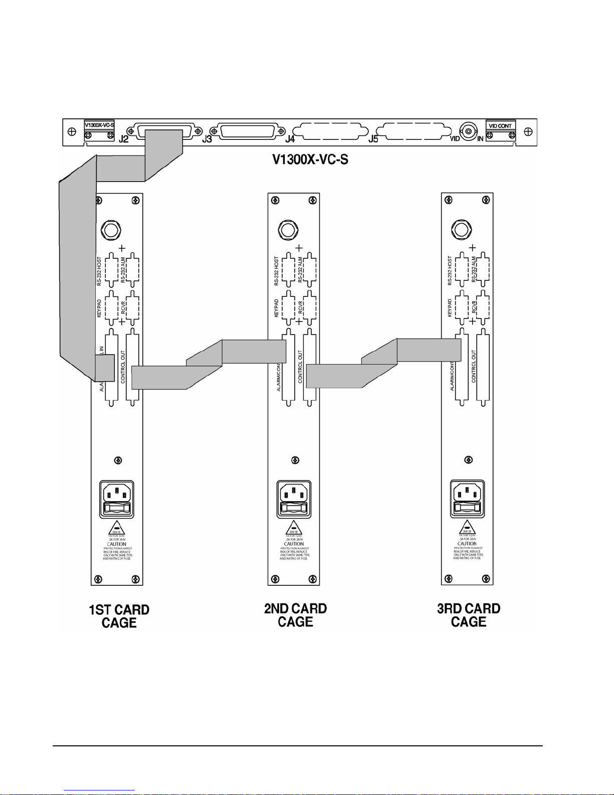
3. Loop control signals from Loop Out on the first card cage to Alarm/Control In on the second card cage, and so forth. The looping
connections between card cages are the same regardless of control system, so you may refer to the V1300 figure on the following
pages even if you have a V1500.
iv • Quick Start X824-05-02 Rev 307 Matrix 66
Page 11
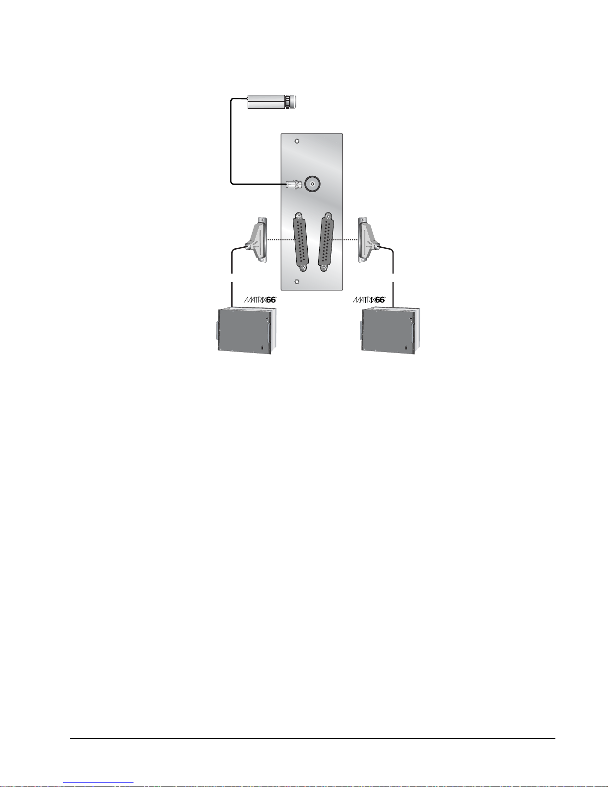
V1500 Control Systems:
Camera
V1500CDU-VID
VIDEO-IN
VIDEO CONTROL 2
VIDEO CONTROL 1
Part No. 1251-3271-01 Part No. 1251-3271-01
KEYBOARD
ON
OFF
VI
C
ON
Connect to External CPU
Control In connector
POWER
V6680SCC
VI
C
ON
Connect to External CPU
Control In connector
KEYBOARD
ON
OFF
POWER
V6680SCC
X824-05-02 Rev 307 Matrix 66 Quick Start • v
Page 12
V1300 Systems:
vi • Quick Start X824-05-02 Rev 307 Matrix 66
Page 13
V1466A System
Example Systems
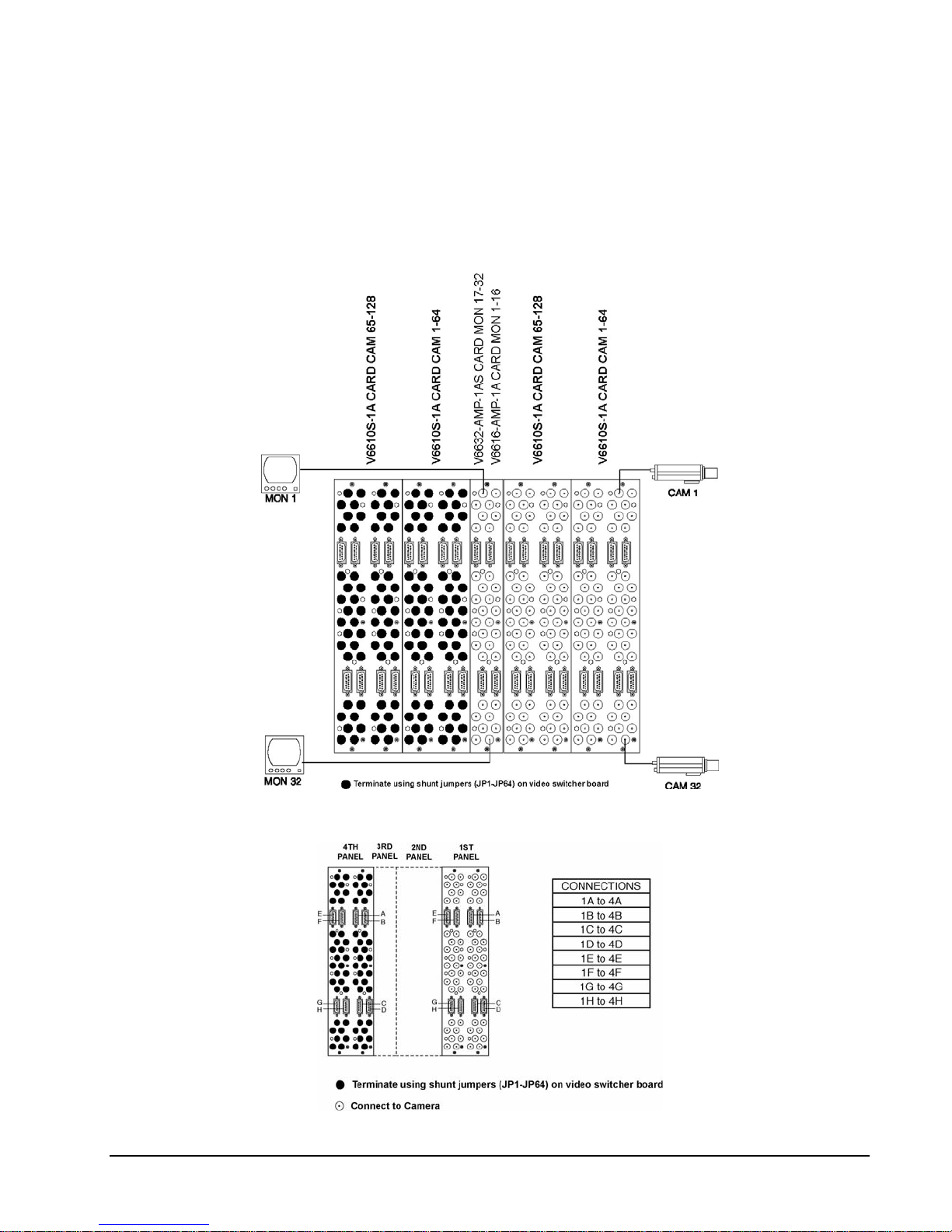
128 camera, 32 monitor system:
A 128 camera, 32 monitor system is shown below. It consists of one card cage only, with the NOVA V1466A
CPU card installed. Camera and monitor connections are indicated, as well as the BNCs that should be
terminated. The connections between BNC panels are shown below for the 128 camera, 32 monitor system.
In the following illustration, only the wiring of the first panel to the 4
th
panel is shown. The 2nd panel to the 5th is
wired in the same manner.
Connections between BNC panels:
X824-05-02 Rev 307 Matrix 66 Quick Start • vii
Page 14
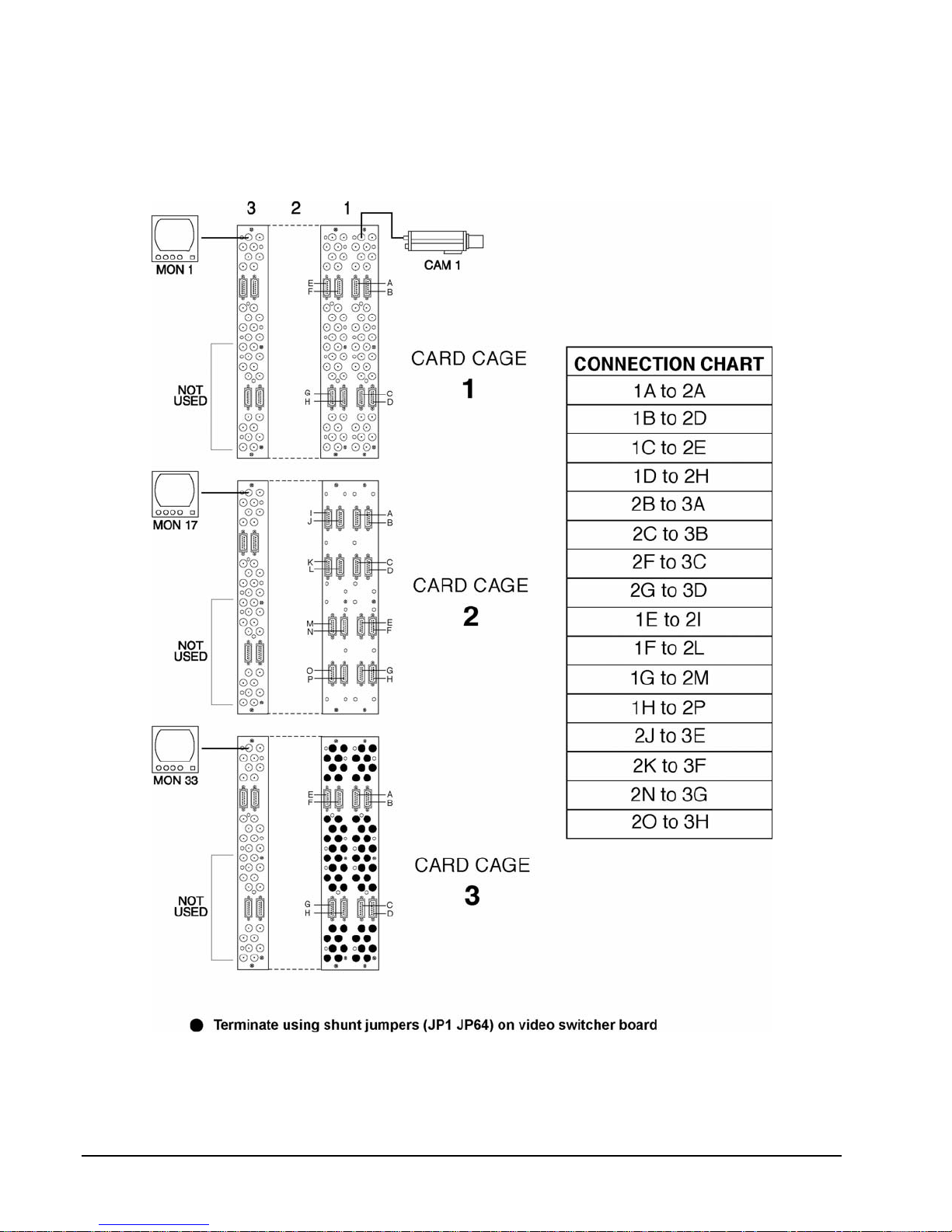
256 camera, 48 monitor system:
The connections between multiple cages are shown for a 256 camera, 48 monitor system. Note that this
system requires the NOVA V1500 or V1300 control system. In the following illustration, only the wiring of the
first panel of each cage is shown. The second, third and fourth panels of each cage is wired the same.
viii • Quick Start X824-05-02 Rev 307 Matrix 66
Page 15
Introduction
Note: Read all of the instructions completely before installing this equipment.
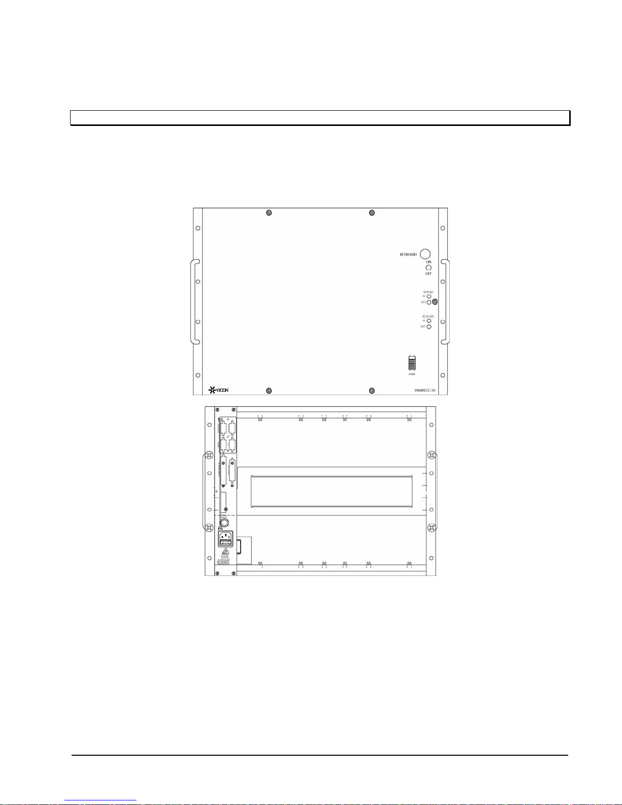
This manual provides information on the installation of the Matrix 66™ Super-High-Density Switcher,
including the installation of the V6680SCC-16-1A or V6680SCC-32-1A card cages and connections to other
equipment. Matrix 66 is a microprocessor-based video switching system that routes video signals from a
specified camera position to a specified monitor. The front and rear of the Matrix 66 card cage is shown in
Figure 1.
Figure 1
Matrix 66 Front and Rear Panels
The card cage can accept up to 256 camera inputs and can route the video to 16 monitor outputs.
Alternatively, a single card cage system can route video to 32 monitors if the maximum number of camera
inputs is limited to 128. Each card cage houses up to 4 video switcher cards, each of which can accept 64
video inputs.
The Matrix 66 card cage is supplied with a mother board and a power supply. The other internal components
include video switcher cards, video amplifier card(s) and expander card(s), which are installed according to
the system size requirements. The specific combination of these cards in a card cage and the number of card
cages required for a system are determined by the size and configuration of the video system it is supporting.
X824-05-02 Rev 307 Matrix 66 Introduction • 1
Page 16
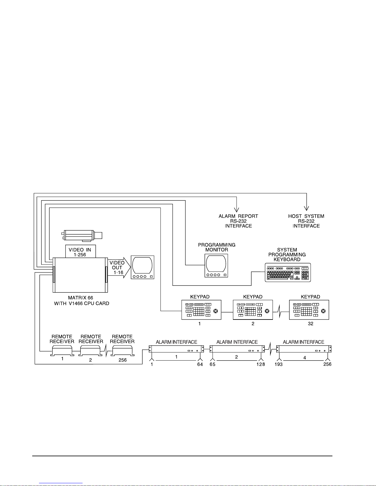
The maximum number of cameras and monitors a system can support depends upon the type of control
system used.
One of three control systems must be used with the Matrix 66: the NOVA V1500 control system, NOVA
V1300 control system or the NOVA V1466A control system. The V1300 or V1500 must be used if the system
size is to exceed 256 cameras, 32 monitors (more than two card cages). The V1300 or V1500 is an external
control system that may include the Matrix 66 as one of its CCTV components. If a V1300 or V1500 control
system is used to control the Matrix 66, a decoder board is required to be inserted in the slot where the CPU
is normally located. The V1466A is an internal printed circuit card that is installed into the Matrix 66 card
cage. External components, such as keypads, receivers and alarm devices are always connected directly to
the control system. In Figure 2, the Matrix 66 is controlled by the V1466A card and therefore the external
CCTV components are connected to the card cage. Note that if the control system is the V1300 or the V1500,
all of the external components and the first Matrix 66 card cage are connected directly to the V1300 or V1500.
Refer to Figure 2A.
This system should only be installed by a qualified technician using common hand tools and approved
materials and wiring methods in accordance with the National Electrical Code ANSI/NFPA 70, state and local
wiring codes. All interconnecting equipment or accessories must be UL Listed. Any mention in this manual of
alarm inputs/outputs have not been evaluated by UL to be used for burglar alarm functionality.
Matrix 66 System with NOVA V1466A Card
2 • Introduction X824-05-02 Rev 307 Matrix 66
Figure 2
Page 17
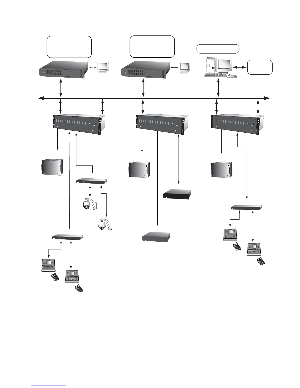
Main CPU Bay
Pentium III 600 MHz
Standard Industrial PC Case
Ethernet Interface
Power
HDD
3.3V
Windows
TM
NTE
Second CPU Bay
Pentium III 600 MHz
Standard Industrial PC Case
Ethernet Interface
Power
HDD
3.3V
Windows
TM
NTE
Running V1500 API
Other
Vendor
Equipment
V1500CPU
V1500CDU
VIDEO SWITCHER
MATRIX
VI
C
ON
2048x128
Matrix support per
parallel card
V1400X-IDL
1
KEYPAD
Ethernet LAN
Two Network Interface Cards
and up to 11 application cards
may be installed in each CDU
V1500
V1500
POWER
OPERATIONAL
ACTIVE
1
2
POWER
VI
C
ON
V1400X-IDL
SWITCH
1
2
3
4
5
6
7
89
10
CDU
POWER
SURVEYOR
DOME
CAMERA
SWITCH
2
3
4
5
6
7
89
10
CDU
POWER
VICON
V1500CPU
Any combination of
application cards may be
installed in each CDU
V1500
V1500
POWER
OPERATIONAL
ACTIVE
1
2
POWER
VI
C
V1500CDU
VIDEO SWITCHER
MATRIX
VI
C
ON
VICON
2048x128
Matrix support per
parallel card
512 alarm input per
ON
V1300X-IA
parallel card
V1300X-IA
VI
C
ON
V1500CDU
V1300X-TCC
V1300X-TCC
VI
C
128 monitor output
per parallel card
ON
Hot Standby Operation is
Achieved by the installation
of two of each application
card type
VIDEO SWITCHER
MATRIX
VI
C
ON
2048x128
Matrix support per
parallel card
Up to 32
keypads
per serial card
POWER
OPERATIONAL
ACTIVE
1
V1400X-IDL
SWITCH
1
2
3
4
5
6
7
89
10
KEYPAD
ON
C
VI
V1500
V1500
2
POWER
VI
C
ON
CDU
POWER
VICON
ON
C
VI
ON
C
VI
Up to 32
keypads
per serial card
ON
C
VI
Sample V1500 System Using Matrix 66 Video Switcher Card Cages
X824-05-02 Rev 307 Matrix 66 Introduction • 3
Figure 2A
Page 18
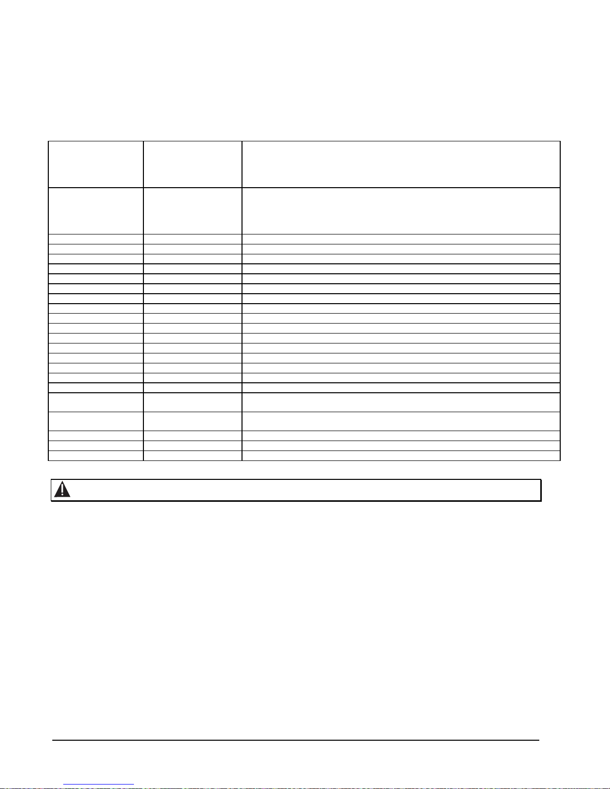
Table 1 lists the model number, product code and a brief description of components which can be purchased
separately. Note that your Matrix 66 system may or may not include these components, depending upon the
requirements of your CCTV system.
Table 1
Matrix 66 System Components
Matrix 66 switcher card cage. Includes power supply and motherboard. Accommodates
V6680SCC-16-1A
V6680SCC-16-1AP
V6680SCC-32-1A
V6680SCC-32-1AP
V1466ADCDB 8173-00 Decoder card. Used in expansion systems, inserted in CPU slot.
V1466ACPU-A 6159-10 Internal CPU card. Limits system size to 256 x 32.
V1466ATDT-SHD-16 4807-10 Time/date/titler OSD card for monitor outputs 1-16.
V1466ATDT-SHD-32 4807-20 Time/date/titler OSD card for monitor outputs 17-32.
V6610S-1A 6023-10 Video switcher card. Accommodates 64 inputs.
V6610RP64-IA 4628-10 64-channel camera input panel.
V6610RP32-IA 4628-20 32-channel camera input panel.
V6610RP16-OA 4628-30 16-channel monitor output panel.
V6610RP32-OA 4628-40 32-channel monitor output panel
V6610RP64-LA 4629-10 64-channel camera looping panel.
V6640SEXP32-A 4470-10 32-channel expander card; for use in star cage expansion configuration.
V6640SEXP16-A 4470-20 16-channel expander card; for use in serial loop expansion configuration.
V6616-AMP-1A 6024-10 Video output amplifier board with outputs for monitors 1-16.
V6632-AMP-1AS 6024-15 Video output amplifier board with outputs for monitors 17-32.
V6670XS-A 4769-10 Card extender for switcher slots (service card).
V6670XA-A 4769-20 Card extender for AMP/OSD slots (service card).
V66RCB-24 4473
V66RC-36 4472
V6650RCP-A 4471-10 Rear closure panel for unused card positions.
V75TR-SHD 4479 75-ohm terminator for D-shell outputs.
V75T 3260 75-ohm terminator for BNC outputs.
6020-20
6020-40
6020-30
6020-60
up to 4 switcher cards and two output amplifier cards or one amplifier card and one
expander card. Available in two input voltages, 120 VAC (6020-20) and 230 VAC
(6020-40). Configured as 256 video inputs x 16 outputs. Use with non-redundant CPU
systems such as theV1300 and V1500 Series.
Matrix 66 switcher card cage. Includes power supply and motherboard. Accommodates
up to 4 switcher cards and two output amplifier cards or one amplifier card and one
expander card. Available in two input voltages, 120 VAC (6020-30) and 230 VAC
(6020-60). Configured as 128 video inputs x 32 outputs. Use with non-redundant CPU
systems such as theV1300 and V1500 Series.
24-inch coaxial ribbon cable for looping video inputs from a switcher card to external
devices. D-shell connector on one end, 8 BNC connectors on the other end.
36-inch coaxial ribbon cable for looping video inputs from one card cage to another. Dshell connector on each end.
Warning: Do not apply power until directed to do so.
4 • Introduction X824-05-02 Rev 307 Matrix 66
Page 19

Preparation
Installing the Matrix 66 in a Rack
The card cage is designed for mounting in a standard 19-inch rack (EIA standard RS-310). Perform the
following procedure to install the card cage in a rack.
Note: It is recommended that two installers work together to mount the card cage(s) in the rack.
1. Plan the layout of the equipment in the racks before installing any equipment. Note that if the V1466A
card will be installed in the system, a keyboard must be connected to the card cage. The placement of
the keyboard should be considered in the layout; the card cage should be positioned so that the attached
keyboard is accessible.
2. Allow a minimum of 1.75 inches of vertical rack space between racked components for ventilation.
Racked components that are a single EIA rack unit in height (1.75 in.) may be grouped in pairs, each pair
being separated from other components by 1.75 inches.
3. The manufacturer of the racking console may or may not include screws for attaching the racked
components to the console. Determine if they will be supplied. If not, be sure to have an adequate supply
of UNF-standard No. 10-32” 3/8 screws for installation.
4. Take an inventory of all rack equipment including hardware, brackets, etc. Reorder any missing parts
immediately. This avoids delays in the middle of the assembly process.
5. Some rack manufacturers supply special mounting hardware. Determine how this hardware is to be used
before attempting to install any racked equipment.
6. Use at least one blower/fan per rack. Place it in the bottom of the rack so that air is drawn in at the bottom
of the rack and vented at the top.
7. One installer should position the rack while a second installer secures it to the front standard.
Tools Required
Vicon does not supply the tools needed in the installation process. If the control system is the internal V1466A
card, receivers and other equipment will be connected to the card cage. In order to do so, you must assemble
D-shell connectors. The following tools will be required in that case:
crimp tool AMP 90302-l or 90312-l
wire stripper.
standard hand tools
If a contact pin is inserted into the wrong connector receptacle, AMP extractor tool 91067-3 will be required to
remove it. You may also need the necessary tools to assemble BNC coaxial cables, depending upon the
number and length of coaxial cables that you have on hand.
X824-05-02 Rev 307 Matrix 66 Preparation • 5
Page 20

Supplied Accessories
The power cable and required number of terminators will be supplied for your Matrix 66, as well as the
appropriate number of control signal looping cables with your order. For the V1466A card, you will receive an
accessory kit that contains the items in Table 2.
Table 2
Contents of Accessory Kit
Item Purpose Qty Vicon Part Number
9-Pin Connectors Connectors for RS-232/RS-422 devices. 4 8000-8595-00-00
Ferrules Reinforces cable-to-connector junction. 4 8000-8594-00-00
Retainers Screw retainers for 9-pin connectors. 4 8000-8595-01-00
Contacts, Pin Used in 9-pin connectors. 36 8000-9571-00-00
Adapter, 25-pin to 37-pin Connects J9 to VI 300X-IA cable. 1 1294-3055-01-00
6 • Preparation X824-05-02 Rev 307 Matrix 66
Page 21

Camera and Monitor Connections
Cameras
Video is usually brought back from the cameras to the Matrix 66 with coaxial cable. Even if some other
transmission medium is used, such as fiber optics or wireless, final connection to the Matrix 66 is made with
coaxial cable. Refer to Reference, Cable Recommendations, Video Cabling for information on the appropriate
video cable for your application.
The rear panel of each card cage contains up to four (4) V6610RP64-IA rear connector panels, referred to in
this text as “BNC” panels. Each BNC panel contains 64 BNC connectors. Perform the following procedure to
connect cameras to the Matrix 66. If you are adding cameras to an existing Matrix 66 system, refer to
Expanding an Existing System.
1. Locate the BNC panels labeled “VID” and numbered in sets of 16. Refer to Figure 3.
2. Connect each camera’s video output connector to the appropriate BNC connector on the Matrix 66 BNC
panels.
V6610RP64-IA BNC Panel Labeled for Camera Inputs
X824-05-02 Rev 307 Matrix 66 Camera and Monitor Connections • 7
Figure 3
Page 22

Monitors
When you purchase the Matrix 66, Vicon’s factory technicians will install the appropriate number and type of
amplifier boards in the card cages. These video amplifier boards process video information before it is sent to
the monitors. As the rear panel of the card cages will be labeled for you at the factory, connecting monitors to
your Matrix 66 is quick and easy. Perform the procedure below to connect monitors to the Matrix 66. If you
are adding monitors to an existing Matrix 66 system, refer to Expanding an Existing System.
1. The card cage to which monitor connections are made depends upon the system size. For example, in a
typical 256 camera x 32 monitor system, 16 monitor connections would be made to each card cage.
However, in a 512 camera x 16 monitor system, the monitor connections will be made to the last card
cage. The appropriate BNC panels will be labeled so that you can identify which panels should be used
for monitor connections. Locate the third BNC panel in each card cage labeled “MON” and numbered in
sets of 16, referring to Figure 4. The “17-32” label may or may not be present, depending upon your
configuration.
2. Connect each monitor’s video input to the appropriate BNC connector on the Matrix 66 BNC panel.
3. If the video is not looped out from the monitor to some other equipment, set the termination switch on the
monitor to the 75 OHM position. If the video will be looped out from the monitor, set the monitor’s
termination switch to HIGH IMPEDANCE or HIGH Z. Repeat for each monitor.
4. Connect a V75T terminator to any unused monitor BNCs on the monitor output panel. For instance, if only
13 monitors are to be connected to the panel, terminate the last three BNCs with V75T terminators. Do
not terminate the two top D-shell looping connectors on the monitor BNC panel on the card cage. This
would create a double-termination condition which can degrade the video image quality.
Figure 4
V6610RP32-OA BNC Panel Labeled for Monitor Output
8 • Camera and Monitor Connections X824-05-02 Rev 307 Matrix 66
Page 23

Programming Monitor
Note: This section is only applicable for Matrix 66 systems using the internal VI466A card. If your control
system is the V1300, make connections to the programming monitor as documented in X553; for the
V1500, reference XX093.
In order to view the programming screens for the V1466A card, you must connect a coaxial cable from a
monitor to the BNC connector on the rear panel of the Matrix 66 card cage. Make this connection to the BNC
connector labeled “STATUS DISPLAY” as shown in Figure 5 below.
Figure 5
Location of Status Display BNC on the Decoder Card
X824-05-02 Rev 307 Matrix 66 Camera and Monitor Connections • 9
Page 24

Single Card Cage Installation
128 Cameras, 32 Monitors
Up to 32 monitor connections are available with one card cage if the maximum number of cameras is limited
to 128. As shown in Figure 6, this configuration requires four V6610S-1A cards, one V6616-AMP-1A and one
V6632-AMP-1AS card. Camera and monitor numbers for each BNC panel are also identified in this figure.
The first two BNC panels (V6610RP64-IA) will be used for camera input. This video must be routed to the last
two panels (V6610RP64-IA) in order to provide the camera video to monitors 17-32. (Note: the cards are
inserted into slots in the card cage behind the BNC panels.)
Perform the following procedure for 128 camera, 32 monitor, single card cage systems.
Note: Single card cage systems are controlled by the V1466A. If you are using the V1300 or V1500, you will
typically have more than one card cage.
1. On the first BNC panel, connect one end of a V66RC cable to the top 2nd from the right D-shell connector.
Connect the other end of the cable to top 2
shown in Figure 7.
10 • Single Card Cage Installation X824-05-02 Rev 307 Matrix 66
Figure 6
128 Camera, 32 Monitor System
nd
from the right D-shell connector on the fourth panel as
Page 25

2. On the first BNC panel, connect one end of a V66RC cable to the top right D-shell connector. Connect
the other end of the cable to the top right D-shell connector of the fourth panel as shown in Figure 7.
nd
3. On the first BNC panel, connect one end of a V66RC cable to the bottom 2
connector. Connect the other end of the cable to the bottom 2
nd
from the right D-shell connector on the
from the right D-shell
fourth panel as shown in Figure 7.
4. On the first BNC panel, connect one end of a V66RC cable to the bottom right D-shell connector.
Connect the other end of the cable to the bottom right D-shell connector on the fourth panel as shown in
Figure 7.
5. Repeat steps 1-4 for the BNC panels used for cameras 33-128. Pair the second and fifth panels. These
connections are not shown in Figure 7 because of space constraints.
6. On the last two BNC panels, terminate the 128 unused camera inputs by using the shunt jumper
terminators. Jumpers JP1-JP64 on the switcher card should all have jumper shunt terminators inserted.
Refer to Figure 7. (Note: JP1 corresponds to Camera 1, JP2 to Camera 2 and so forth.).
Note: The shunt jumper terminators should be preinstalled on the switcher cards but may be supplied in the
accessory kit. For a single card cage installation, all the camera inputs for the last two BNC panels
should have the jumper shunt terminators inserted on the associated switcher card (JP1-JP64) to
terminate. On the switcher cards associated with the first two panels, all the shunt jumper terminators
should be removed.
Connections for 128 Camera, 32 Monitor System
256 Cameras, 16 Monitors
A 256 camera, 16 monitor configuration requires only one card cage. Unlike the 128 camera, 32 monitor
configuration, you do not need to make any looping connections from panel to panel. Make connections to
cameras and monitors as discussed previously and make any other appropriate connections discussed
in the other sections of this manual.
X824-05-02 Rev 307 Matrix 66 Single Card Cage Installation • 11
Figure 7
Page 26

Multiple Card Cage Installation
A single card cage system supports one of two configurations: 256 cameras, 16 monitors or 128 cameras, 32
monitors. Any system larger than those two configurations requires multiple card cages. You may expand a
V1466A system to two card cages, for a system size of 256 cameras and 32 monitors. Any system larger
than that requires an external control system such as the V1300 or V1500. If more card cages are added in
order to increase the number of monitors, then the camera video must be looped to the next card cage(s). In
a similar manner, if more card cages are added in order to increase the number of cameras, then the monitor
video must be looped to the next card cage(s).
Looping Camera Video
In general, more than one card cage is required in order to provide more than 16 monitor outputs. Camera
inputs must be looped from card cage to card cage in order to view the video from these cameras on all of the
monitors. This procedure is given below.
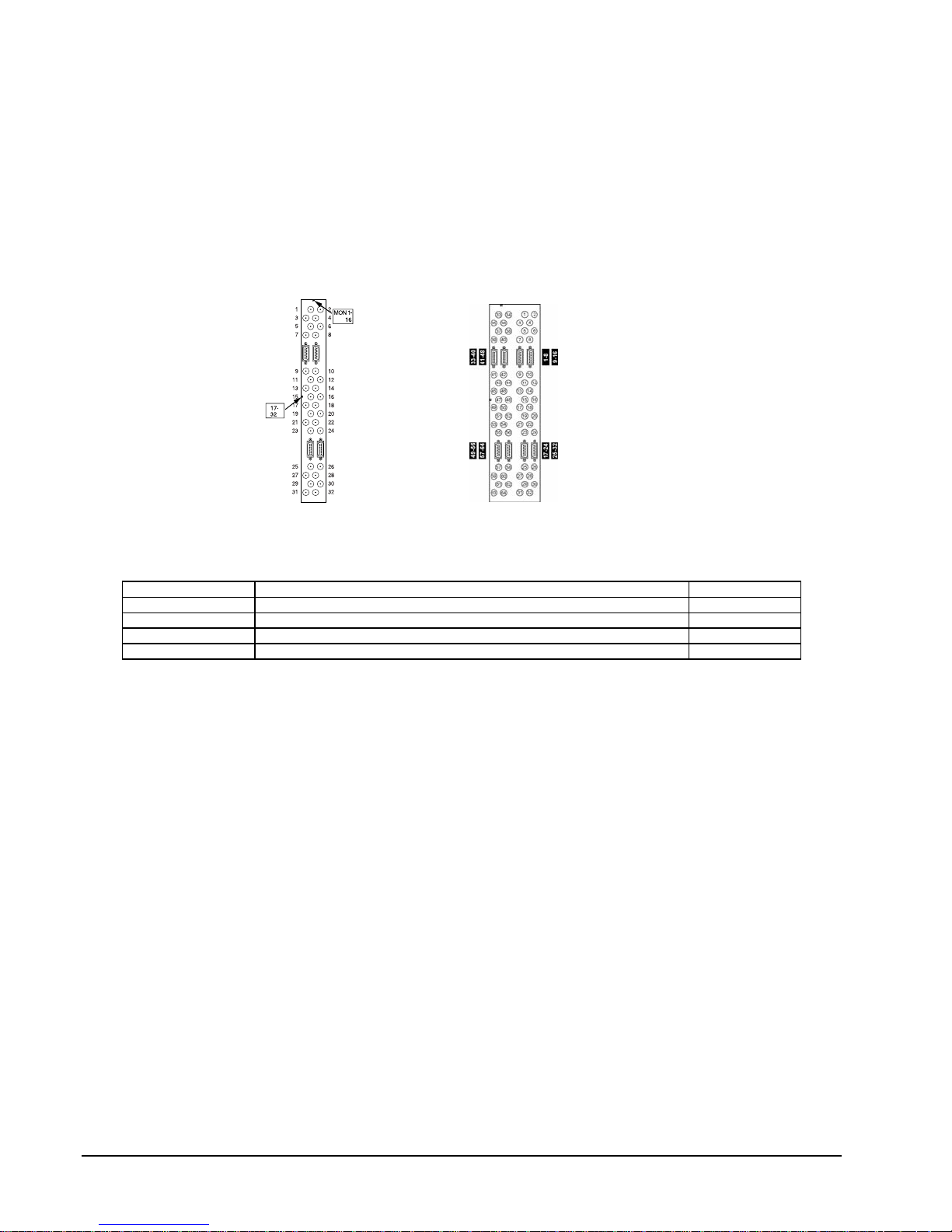
1. In Figure 8, each D-shell connector on V6610RP64-IA panels provides outputs for eight video channels.
Notice that on the V6610RP64-LA panels (shown on the right below), each set of D-shell connectors is
electrically equivalent, with either connector in a set providing outputs for eight video channels.
Looping Connectors on V6610RP64-IA (left) and V6610RP64-LA Panels (right)
2. On the first BNC panel on the right-hand side of the first card cage, connect one end of a V66RC cable to
the top right D-shell connectors (labeled “Camera 1-8” in Figure 8). Connect the other end of the cable to
the appropriate D-shell connector in the appropriate card cage as shown in Figure 9. The panel may be a
V6610RP64-IA or a V6610RP64-LA, depending upon the number of card cages in your system. Figure 9
shows both configurations. Typically, the first and last card cages use V6610RP64-IA BNC panels and
V6610RP64-LA panels are installed in the intermediate cages.
3. On the first BNC panel of the first card cage, connect one end of a V66RC cable to the second D-shell
connectors (labeled “Camera 9-16” in Figure 8). Connect the other end of the cable to the D-shell
appropriate connector in the appropriate card cage as shown in Figure 9.
4. Continue to connect the remaining D-shell connectors for the looping outputs for cameras 17-24, 25-32,
33-40, 41-48, 49-56 and 57-64.
5. If your system includes more than two card cages, continue to loop video down to the subsequent card
cages, referring to Figure 9 and the examples in Figures 11 and 13.
12 • Multiple Card Cage Installation X824-05-02 Rev 307 Matrix 66
Figure 8
Page 27

6. Using the shunt jumper terminators, terminate the 64 unused BNC connectors on each of the BNC panels
in the last card cage as shown in Figure 9. (Note: On the panels before the last one, the shunt jumper
terminators JP1-JP64 should all be removed on the associated switcher cards.)
7. Repeat steps 3 - 7 for the remaining video looping panels in the system (the second, fourth, and fifth
panels – the third panel is for monitor outputs).
Looping Camera Video in Multiple Card Cage Systems
X824-05-02 Rev 307 Matrix 66 Multiple Card Cage Installation • 13
Figure 9
Page 28

Camera Expansion Using Serial Loop Configurations
(Monitor Looping)
Monitor video must be looped from card cage to card cage when the maximum number of cameras exceeds
256. Perform the following procedure if your system size is larger than 256 cameras (two or more card
cages).
1. Locate the V6610RP32-OA BNC panels labeled “MON” in the card cages (third panel from the right, with
card cage viewed from the rear). Connect a coaxial cable from the first BNC connector in the first card
cage to the seventeenth BNC connector in the second card cage as shown in Figure 10.
2. Repeat this process, connecting the second BNC on the “MON” panel in the first card cage to the
eighteenth BNC on the “MON” panel in the second card cage, and so forth, as shown in the following
table. The numbers in the table refer to the BNCs labeled in the figure to the right below.
1st Card
Cage
1 17
2 18
3 19
4 20
5 21
6 22
7 23
8 24
9 25
10 26
11 27
12 28
13 29
14 30
15 31
16 32
2nd Card
Cage
Looping Monitor Video in Multiple Card Cage Systems
3. Repeat the steps above for subsequent card cages. In systems that have more than 256 cameras and
more than 16 monitors, V6640SEXP16-A Expander Cards must be used. While the monitor looping is
basically the same for very large systems as discussed in this procedure, it may be helpful to refer to
illustrations in the next section.
Camera Expansion Using Star Cage Configuration
Figure 14 also illustrates another method of expanding systems with camera size more than 256. Instead of
looping monitors, an additional card cage with V6640SEXP32-A boards is used for camera expansion (4th
14 • Multiple Card Cage Installation X824-05-02 Rev 307 Matrix 66
Figure 10
Page 29

cage in Figure 14). This method can be configured to any camera size up to 2048 and is the preferred
method if the camera size in the system exceeds 512.
Large System Examples
256 Camera, 48 Monitor System
In a 256 camera, 48 monitor system, the number of monitors exceeds the maximum allowed for one card
cage. Therefore, additional card cages are required for each set of 16 monitors, for a total of three cages.
When the number of monitors necessitates additional cages, camera video must be looped down to the
additional cages so that this video is available for all monitors. As shown in Figure 11, video is looped from
the first to the second and from the second to the third card cages. Monitors are connected to the first sixteen
BNCs of the monitor output panel (the third panel from the right, viewing the cage from the rear) of each cage.
The first card cage supports monitors 1-16, the second cage supports monitors 17-32 and monitors 33-48 are
connected to the third cage. Cameras 1-256 are connected to the first card cage, 64 cameras per panel. The
BNCs on the third card cage’s BNC panels (all panels except the third) are terminated using the shunt jumper
terminators (JP1-JP64) located on the associated switcher card.
Connections for 256 Camera, 48 Monitor System
X824-05-02 Rev 307 Matrix 66 Multiple Card Cage Installation • 15
Figure 11
Page 30

512 Camera, 16 Monitor System
In a system that requires more than 256 cameras but only 16 monitors, an additional card cage will be
needed for each set of 256 cameras. As shown in Figure 12, 64 cameras are connected to each BNC panel
of each card cage (except the third panel, which is used for monitor outputs). The first 256 cameras are
connected to the first card cage, continuing on the second card cage with 64 cameras per BNC panel
(excluding the third panel) until all 512 cameras are connected. Insert shunt jumpers (JP1-JP64) on all
switcher cards.
The sixteen monitors are connected to the first sixteen BNCs on the third BNC panel of the second card cage.
Coaxial cables are connected, started with the first BNC from the monitor output panel of the first card cage to
the seventeenth BNC on the same panel in the second card cage, the corresponding second BNC to the
eighteenth BNC on the second card cage, and so forth. Because of space constraints, only the first cable is
shown in the figure. Refer to Camera Expansion Using Serial Loop Configuration for more information on
monitor connections between the card cages.
Connections for 512 Camera, 16 Monitor System
16 • Multiple Card Cage Installation X824-05-02 Rev 307 Matrix 66
Figure 12
Page 31

512 Camera, 32 Monitor System
In the previous two examples, more than one card cage was needed because of the need for more than 256
cameras or more than 16 monitors. In this example, the system specifications are 512 cameras and 32
monitors. This requires four card cages, as both monitor and camera cables must be looped to additional
card cages in order to achieve the maximum number of monitors and cameras.
Figure 13 shows Camera 1 connected to the first card cage, which is shown at the top left. Cameras 2-256
are also connected to this card cage, though not shown because of space constraints. Cameras 257-512 are
connected to the second card cage, which is shown at the top right. The camera video is looped from these
cages down to the third and fourth card cages. Because more than 256 cameras are required, the second
and fourth card cages (top and bottom right) include a V6640SEXP16-A Expander Card.
Sixteen monitors are connected to the first sixteen BNCs of the third panel in the second and fourth card
cages (top and bottom right cages). Coaxial cables are connected to the first sixteen monitor outputs in the
first and third card cages to the last sixteen BNCs in the third panels of the second and fourth cages.
Connections for 512 Camera, 32 Monitor System
X824-05-02 Rev 307 Matrix 66 Multiple Card Cage Installation • 17
Figure 13
Page 32

768 Camera, 16 Monitor System
In a 768 camera system, two V6640SEXP32-A Expander Cards are required. These expander cards are
housed in a fourth card cage, which will not contain any video switcher cards. As shown in Figure 14, the first
sixteen monitors’ BNCs on the first cage are routed to the top right sixteen BNCs on the fourth card cage. The
first 16 monitors’ BNCs on the 2
connected to the last card cage, as is typically the case. Though not shown in Figure 14, 256 cameras are
connected to each of the first three card cages and because the number of monitors is 16, camera video is
not looped out.
nd
cage are routed to the top left 16 BNCs on the 4th card cage. Monitors are
Connections for 768 Camera, 16 Monitor System
Looping Control Signals
Control signals from an external control system (V1300 or V1500) must be looped from card cage to card
cage as discussed in the following procedure.
1. Connect the V1300 or V1500 Video Control CPU to the Matrix 66 Alarm/Control In connector.
2. Connect the supplied control cable to the Control Out connector of the first card cage.
3. Connect the other end to the Alarm/Control In connector on the second card cage.
4. Continue to connect between the Control Out connector of one card cage to the Alarm/Control In
connector of the next card cage. Refer to Figure 15.
18 • Multiple Card Cage Installation X824-05-02 Rev 307 Matrix 66
Figure 14
External Control System
Page 33

A system controlled by the V1466A has a maximum system size of 256 cameras and 32 monitors. A system
this size requires two card cages.
Using the supplied control cable, connect J11 Control Out of the first card cage (card cage that contains the
V1466A CPU card) to Alarm/Control In of the second card cage (card cage that contains the V1466ADCDB
Decoder Card).
X824-05-02 Rev 307 Matrix 66 Multiple Card Cage Installation • 19
Figure 15
Looping Control Signals
V1466A System
Page 34

Expanding an Existing System
Cameras
As each configuration is unique, the instructions for adding new cameras are generalized as follows.
Situation Solution Otherwise…
You have free BNCs. Connect cameras. If you now have more
than 256 cameras, add V6640SEXP16-A
card to fourth slot. Set SW1 on decoder
card (see Figure 16).
You have a blank
V6650RCP-A panel.
Additional V6610S-1A switcher cards and rear panels are added to a cage as a set, one card and one panel
being required. Before the V6610S-1A switcher card is installed in the cage from the front, shunt jumper
terminators JP1 to JP64, which are jumper to 75 ohms video terminators, must be configured. These shunts
will have to be inserted or removed depending if the camera input to the switcher board is part of a video loop
system or is a final termination of a video source (from an end of a video looped source or directly from a
video source). Insert shunt jumper terminator(s) if end of video termination is required. Otherwise, remove the
jumper terminator(s) for no video termination. Additional shunt configuration is required as follows.
On a V1466A system, setting the address for the additional switcher card is not required, but the shunt
jumpers on the card need to be set for V1466A as follows.
Switcher Card:
1. JP65 -
a. Shunt removed for the cage with the internal CPU (monitor 1 – 16)
b. Shunt shorted for the cage with the decoder board (monitor 17 – 32).
2. JP66, JP67 and JP68 - Pin 1 and 2 shunt shorted (On a 32 monitor V1466A single cage system,
remove JP67 on all switcher cards)
On a Matrix 66 with an external CPU system, the additional switcher card will require address settings from
the decoder card (refer to Camera and Monitor Addressing) and shunt settings from the switcher card as
follows:
Switcher Card:
1. JP65 - follows the MON4 setting of the decoder card
a. Removed for MON4 = 0
b. Inserted for MON4 = 1
2. JP66, JP67 –Shunts are removed
3. JP68 – Pin 2 and 3 shunt shorted
To add new cards, remove the front panel of the Matrix 66 and insert the card into the appropriate empty slot,
taking all necessary precautions to prevent static discharge. Lock the cards into place using the inserter clips.
If necessary, the V6610S-1A card should be inserted into the first empty slot (excluding the third and fourth
slots).
Add new V6610S-1A card and
V6610RP64-IA rear panel. Connect
cameras. Set DIP switches and the shunt
jumpers on decoder card and on video
switcher card (see Figure 16).
If you have a blank V6650RCP-A
panel, refer to the next situation.
Otherwise, you must add a new
cage.
Add new card cage to your system.
20 • Expanding an Existing System X824-05-02 Rev 307 Matrix 66
Page 35

To add a new V6610RP64-IA rear panel, remove the rightmost V6650RCP-A blank panel on the rear of the
card cage. Use the captive screws at the bottom and top of the rear panel to secure the panel in place.
If necessary, add a new card cage to your system and loop camera and/or monitor video down to the new
cage. Replace the front cover of the Matrix 66. If labels were provided from Vicon, attach them to the new
panel(s), using the appropriate numbers. Refer to the following sections if necessary:
Camera and Monitor Connections
Multiple Card Cage Installation
Camera and Monitor Addressing
Monitors
As each configuration is unique, the instructions for adding new monitors are generalized as follows.
Situation Solution Otherwise…
You have free BNCs on the “MON”
panel to which monitors are already
connected.
No free BNCs on the “MON” panel to
which monitors are already connected.
If necessary, add a new card cage to your system by looping camera and/or monitor video down to the new
cage. If labels were provided from Vicon, attach them to the new panel(s), using the appropriate numbers.
Refer to the following instructions if necessary:
Camera and Monitor Connections
Multiple Card Cage Installation
Camera and Monitor Addressing
Connect monitors. You must add a new cage.
Add a new card cage and connect
monitors. Set SW1 on the decoder
card (see Figure 16).
N/A
Camera and Monitor Addressing
Note: Switches are set at the factory. Do not perform this procedure unless you are expanding your system.
As discussed in Camera and Monitor Connections, the BNC panel in the extreme right card slot (viewing the
Matrix 66 card cage from the rear) is used for cameras 1-64. The next BNC panel is used for cameras 65128, and so forth in an increasing camera number order. Refer to Tables 3, 4, and 5.
On a V1466A System: In order to identify to the card cage which V6610S-1A video switcher card will be
used for which set of 64 cameras, each slot of the cage has a fixed address that represents the camera
address range. Therefore, the camera address range of Slot A (far left slot of the cage viewed from the front
of the cage) is Camera 1 to Camera 64, Slot B is Camera 65 to Camera 128, Slot C is Camera 129 to
Camera 192, and Slot D is Camera 193 to Camera 256. If the V1466A system has a second cage added, the
same slot scheme used on the first cage is used on the second cage. On the monitor’s side, the V1466A can
only address Monitor 1 thru Monitor 32. One V1466A cage can only support up to 16 monitors. (This is for a
256 x 16 configuration; see Single Card Cage Installation, 128 Cameras, 32 Monitors for a 128 x 32
configuration.) If more than 16 monitors are required, a second cage must be added to the V1466A system.
The second cage will add 16 monitors to the system. Switcher cards that are in the cage with the Internal
CPU will address Monitor 1 thru Monitor 16 and will have their shunts configured as follows:
X824-05-02 Rev 307 Matrix 66 Expanding an Existing System • 21
Page 36

1. JP65 - Shunt removed
2. JP66, JP67 and JP68 – Pin 1 and 2 shunt shorted
Switcher cards that are in the cage with the decoder card will address Monitor number 17 thru 32 and will
have their shunts configured as follows:
3. JP65 - Shunt shorted
4. JP66, JP67 and JP68 – Pin 1 and 2 shunt shorted
Note: The V1466A does not use any settings of the DIP switches and shunts that are on the decoder card
(second cage).
On a Matrix 66 with an External CPU System: In order to identify to the card cage which V6610S-1A video
switcher card will be used for which set of 64 cameras, each slot of the cage is addressed using the shunts
on the switcher cards and the DIP switch settings and shunts on the decoder board. The slots in the card
cage are identified from left to right viewing the cage from the front as Slot A, Slot B, Slot C and Slot D. These
slots are selected by the address configuration set by the DIP switches located on the decoder board. These
slots are also used by the expander card(s) when expansion beyond a single cage is required. The expander
cards are also addressed by the decoder card. DIP switch settings and shunts on the decoder card for the
switcher card or the expander card in each slot are shown in Figure 16, A - D.
Perform the following procedure, noting that the procedure starts with the first switcher card; typically, you will
only need to set switches on the cards that you add to the system because switches on existing cards will be
set at the factory.
1. Remove the front panel of the Matrix 66. Referring to Figure 16/A, locate shunts JP65, JP66, JP67 and
JP68 on video switcher card.
2. Set the shunts of the switcher card and the shunts and DIP switches of the decoder card (Figure 16/B) as
shown in Tables 3-5.
3. Repeat step 2 for each video switcher card used for camera connections. Examples of shunt and DIP
switch settings for both switcher and decoder cards are shown in the following section.
4. If the system has more than 256 cameras (two or more card cages), you must add either a
V6640SEXP16-A or V6640SEXP32-A card(s) (Figure 16/C-D) to your card cage’s configuration. If a
V6640SEXP32-A is used, insert a shunt on JP65 of the card when the video outputs of one additional
cage (256 cameras) is connect to the expander. If two additional cages are connected to the same
V6640SEXP32-A board (512 cameras), then remove shunt on JP65.
5. When either a V6640SEXP16-A or V6640SEXP32-A card(s) is added in the expansion of a video
switching system, it is important to configure the decoder card to the cage slot that has the expander
card. On the decoder card, locate jumpers and DIP switches and configured them as shown in Figure 16.
Examples of shunt and DIP switch settings for both expander and decoder cards are shown in the
following section.
22 • Expanding an Existing System X824-05-02 Rev 307 Matrix 66
Page 37

X824-05-02 Rev 307 Matrix 66 Expanding an Existing System • 23
Figure 16
Location of DIP Switches and Shunt Jumpers
Page 38

Location of DIP Switches and Shunt Jumpers
24 • Expanding an Existing System X824-05-02 Rev 307 Matrix 66
Figure 16, continued
Page 39

Table 3
Camera Addressing
SW 2 (Camera Slot B), SW3 (Camera Slot C), SW4 (Camera Slot D), SW7 (Camera Slot A)
for V6610S-1A Video Switcher Card and V6640SEXP32A Expander Card
Camera Pole Number (Camera Number)
1 (C6) 2 (C7) 3 (C8) 4 (C9) 5 (C10)
1-64 OFF OFF OFF OFF OFF
65-128 ON OFF OFF OFF OFF
129-192 OFF ON OFF OFF OFF
193-256 ON ON OFF OFF OFF
257-320 OFF OFF ON OFF OFF
321-384 ON OFF ON OFF OFF
385-448 OFF ON ON OFF OFF
449-512 ON ON ON OFF OFF
513-576 OFF OFF OFF ON OFF
577-640 ON OFF OFF ON OFF
641-704 OFF ON OFF ON OFF
705-768 ON ON OFF ON OFF
769-832 OFF OFF ON ON OFF
833-896 ON OFF ON ON OFF
897-960 OFF ON ON ON OFF
961-1024 ON ON ON ON OFF
1025-1088 OFF OFF OFF OFF ON
1089-1152 ON OFF OFF OFF ON
1153-1216 OFF ON OFF OFF ON
1217-1280 ON ON OFF OFF ON
1281-1344 OFF OFF ON OFF ON
1345-1408 ON OFF ON OFF ON
1409-1472 OFF ON ON OFF ON
1473-1536 ON ON ON OFF ON
1537-1600 OFF OFF OFF ON ON
1601-1664 ON OFF OFF ON ON
1665-1728 OFF ON OFF ON ON
1729-1792 ON ON OFF ON ON
1793-1856 OFF OFF ON ON ON
1857-1920 ON OFF ON ON ON
1921-1984 OFF ON ON ON ON
1985-2048 ON ON ON ON ON
X824-05-02 Rev 307 Matrix 66 Expanding an Existing System • 25
Page 40

Table 4
Monitor Addressing
SW 6
Monitors Pole Number (Monitor Number)
1 (M4) 2 (M5) 3 (M6) 4 (M7)
1-16 OFF OFF OFF OFF
17-32 ON OFF OFF OFF
33-48 OFF ON OFF OFF
49-64 ON ON OFF OFF
65-80 OFF OFF ON OFF
81-96 ON OFF ON OFF
97-112 OFF ON ON OFF
113-128 ON ON ON OFF
129-144 OFF OFF OFF ON
145-160 ON OFF OFF ON
161-176 OFF ON OFF ON
177-192 ON ON OFF ON
193-208 OFF OFF ON ON
209-224 ON OFF ON ON
225-240 OFF ON ON ON
241-256 ON ON ON ON
Table 5
V6640SEXP16-A Expander Card Addressing
SW1
Monitors Pole Number (Monitor Number)
1 (M4) 2 (M5) 3 (M6) 4 (M7)
1-16 OFF OFF OFF OFF
17-32 ON OFF OFF OFF
33-48 OFF ON OFF OFF
49-64 ON ON OFF OFF
65-80 OFF OFF ON OFF
81-96 ON OFF ON OFF
97-112 OFF ON ON OFF
113-128 ON ON ON OFF
129-144 OFF OFF OFF ON
145-160 ON OFF OFF ON
161-176 OFF ON OFF ON
177-192 ON ON OFF ON
193-208 OFF OFF ON ON
209-224 ON OFF ON ON
225-240 OFF ON ON ON
241-256 ON ON ON ON
Cameras Pole Number (Camera Number)
5 (C8) 6 (C9) 7 (C10) 8 (C11)
1-256 OFF OFF OFF OFF
257-512 ON OFF OFF OFF
513-768 OFF ON OFF OFF
769-1024 ON ON OFF OFF
1025-1280 OFF OFF ON OFF
1281-1536 ON OFF ON OFF
1537-1792 OFF ON ON OFF
1793-2048 ON ON ON OFF
26 • Expanding an Existing System X824-05-02 Rev 307 Matrix 66
Page 41

Examples
256 Camera, 48 Monitor System
Each V6610S-1A video switcher card is used for 64 cameras. The range of camera numbers is constant
down the rear panels of the card cage; for example, the first rear panel on the right-hand side of each of the
three card cages is labeled for cameras 1-64. (As shown in Figure 11, this video must be looped down from
the first card cage to the second and from the second to the third.) The third rear panel holds the V6616AMP-1A video amplifier card. Each cage is used for 16 monitors, for a total of 48 monitor outputs.
All the switcher cards in the examples should have their shunt jumpers removed on JP66, JP67 and JP68.
The setting of JP65 of the switcher card along with the setting of the shunts and DIP switches on the decoder
card are shown in Figure 16. Note that the setting of JP65 will always follow the setting of “MON4” of the
decoder board.
JP65 - follows the MON4 setting of the decoder board
a. Removed for MON4 = 0
b. Inserted for MON4 = 1
512 Camera, 16 Monitor System
In a 512 camera, 16 monitor system, a V6640SEXP16-A Expander Card is required in the last card cage (see
Figure 12).
768 Camera, 16 Monitor System
In previous examples, shown in Figure 12, the monitor video was looped between cages via a
V6640SEXP16-A Expander Card (serial looped cage configuration) in order to increase the camera size
beyond 256. The examples were limited to 2 cages. The V6640SEXP16-A can be used to loop more than 2
cages and save an extra cage in the expansion. As discussed in Multiple Card Cage Installation, Large
System Examples, 768 Cameras, 16 Monitor System, V6640SEXP32-A Expander Cards are required for
systems with more than 256 cameras. Connections are shown in Figure 14. These expander cards are
placed in the last card cage. The DIP switches on the last card cage’s decoder card are configured as shown
in Tables 3-5.
X824-05-02 Rev 307 Matrix 66 Expanding an Existing System • 27
Page 42

Adding a VI466A CPU Card
• If you want to convert an existing V1500/V1300 Matrix 66 system to a system that uses the V1466A,
you can do so by using the following procedure. Note that you may not expand a VI466A system to
more than 256 cameras, 32 monitors (2 card cages).
Warning: Failure to perform this procedure properly may result in equipment damage.
1. If you were previously using the V1500/V1300 control system with the Matrix 66, remove power from the
units and disconnect the V1500/V1300 control system from the Matrix 66. After performing this
procedure, the control system will be the V1466A internal control system.
2. Remove the front cover of the Matrix 66.
3. The connector cover is at the top left of the unit as viewed from the rear. Remove the connector cover
from the rear of the unit.
4. On the V1466A card, locate the BNC connector. Remove the BNC nut and washer. Do not discard.
5. Taking precautions to prevent static discharge, insert the V1466A card (model number V1466ASCPU-A)
into the extreme right slot as viewed from the front. Seat the 25-pin male D-shell connector on the
V1466A card into the D-shell connector located on the inside of the card cage. Make sure that the BNC
and D-shell connectors on the outside of the card cage (left rear of the cage) are seated properly.
6. Replace the washer and nut on the BNC connector located at the top left of the card cage (viewed from
the rear).
7. You must connect J2 on the power supply board to J5 on the V1466A card; this supplies the card with 5
volts. Use the 3-pin connector. There is also a 2-pin connector on J2 for video sync connection, which
connects to J6 on the V1466A card. Make these connections as shown in Figure 17 and then replace the
front cover.
28 • Expanding an Existing System X824-05-02 Rev 307 Matrix 66
Figure 17
Page 43

VI466A to Matrix 66 Connections
8. With the V1466A card installed, you will have a keyboard DIN connector on front of the unit for a
programming keyboard and a BNC connector on the left rear of the unit for the programming monitor.
Referring to Figure 18, locate the ON/OFF switch S1 and set it to the OFF position. Then connect the
keyboard connector to the DIN connector of the V1466A card and switch S1 to the ON position. Proceed
to the next section if installing the titler card.
Note: Although enabled for use, the clustered cursor keys that sit between the QWERTY and Numeric
sections of the keyboard have proven to be unreliable. Using these keys may cause the cursor to jump
more than one space in the edit screen or skip over the desired edit field. Vicon recommends that
users use the embedded cursor keys of the Numeric section of the keyboard for all editor cursor
movements. These cursor keys can be found as part of the number 2, 4, 6, and 8 keys of the Numeric
keypad.
X824-05-02 Rev 307 Matrix 66 Expanding an Existing System • 29
Figure 18
NOVA V1466A CPU Card
Page 44

Adding a VI466A Titler Card
Note: This section is only applicable to a Matrix 66 system controlled by the VI466A CPU card.
To add time, date and titling capabilities to your Matrix 66 system, a Vl466ATDT-SHD-16/-32 card must
replace the existing V6616-AMP-1A (or V6632-AMP-1AS) that is in your system. This is typically done at the
factory. To add a titler card to an existing system, perform the following procedure.
1. Remove the front cover of the Matrix 66. Taking precautions to prevent static discharge, remove the
V6616AMP-1A board from the third slot (counting from the left, viewing the unit from the front).
2. In a 128 camera, 32 monitor system, you must also remove the V6632AMP-1AS card from the fourth slot.
In a 256 camera, 32 monitor system, you must remove the V6616AMP-1A card from the second card
cage (third slot). Refer to Figure 19.
3. Locate JPI on the V1466ATDT-SHD-16/-32 titler card. JPI is a 2-pin jumper. With the component side of
the board facing you, remove the shunt to JP1 if the titler card to be placed in the card cage is for monitor
outputs 1-16. For a card cage with monitor outputs 17-32, insert the shunt to JP1.
4. Locate the V1466ATDT-SHD-16/-32 Titler Card potentiometers listed in the following table. They may be
used to adjust brightness after all installation procedures are complete. Refer to Figure 19.
30 • Expanding an Existing System X824-05-02 Rev 307 Matrix 66
Figure 19
V1466A Titler Card
Page 45

Potentiometer Monitors
st
Titler Card)
(1
Monitors
(2nd Titler Card,
if applicable
R4 1 17
R9 2 16
R23 3 19
R20 4 20
R36 5 21
R39 6 22
R53 7 23
R50 8 24
R64 9 25
R67 10 26
R81 11 27
R78 12 28
R92 13 29
R95 14 30
R109 15 31
R106 16 32
5. Replace the V1466ATDT-SHD-16/-32 cards into the third slot or fourth slots (counting from the left,
viewing the unit from the front). Use the inserter clip to lock the card in place and replace the front cover.
X824-05-02 Rev 307 Matrix 66 Expanding an Existing System • 31
Page 46

External Control System Connections
In order to control the Matrix 66 with an external control system (V1500/V1300), you must make a hard-wired
connection between the Matrix 66 card cage(s) and the external CPU. Connect the supplied cable between
the Alarm/Control In connector of the first card cage and the appropriate connector as listed in the following
table. The “Monitors” column indicates the hardware address of the monitors that will be switched at the
specified connector. Refer to the following figures.
Table 6
Control System Connectors
Control System Connector Monitors
V1500 Control 1 on V1500CDU-VID (or V1500CDU-HSB-VID) 1-64
V1500 Control 2 on V1500CDU-VID (or V1500CDU-HSB-VID) 65-128
V1300 J2 on V1300X-VC-S (or –F) 1-128
V1300 J3 on V1300X-VC-S (or –F) 129-256
Note: It is important to note that the DIP switches labeled M4 and M5 on the decoder card are only used with
the V1500 system. M6 and M7, also on the decoder card, should always be set to OFF when the
Matrix 66 is controlled by the V1500. M4 and M5 are configured per Table 4.
1500 Systems:
Camera
V1500CDU-VID
VIDEO-IN
Part No. 1251-3271-01 Part No. 1251-3271-01
KEYBOARD
VI
C
ON
Connect to External CPU
Control In connector
POWER
VIDEO CONTROL 2
ON
OFF
V6680SCC
VIDEO CONTROL 1
VI
C
ON
Connect to External CPU
Control In connector
KEYBOARD
ON
OFF
POWER
V6680SCC
32 • External Control System Connections X824-05-02 Rev 307 Matrix 66
Page 47

V1300 Systems:
Control Signal Connections for External Control Systems
X824-05-02 Rev 307 Matrix 66 External Control System Connections • 33
Figure 20
Page 48

Keypad and Receiver Connections
Note: This chapter is only applicable for Matrix 66 systems using the internal V1466A CPU card, If your
control system is the V1500/V1300, make connections to the keypad(s) as documented in XX093 or
X553, respectively.
Remote Keypads
Up to 32 keypads may be connected to the Matrix 66. These keypads are used to control remote positioning
of pan-and-tilt drives, lens functions, alarm acknowledgment and receiver communications failure
acknowledgment. Perform the following procedure to connect remote keypads to the Matrix 66 card cage.
1. Keypads may be connected in a daisy-chain or star configuration. Refer to Figure 27.
2. The CPU/Decoder rear panel is located at the left rear of the card cage. Locate J3 as shown in Figure 21
below.
Figure 21
Location of J3 on CPU/Decoder Rear panel
3. Select the following from the accessory kit:
• 9-pin D-shell connector
• ferrule with outer and inner shell
• contact pins
4. Assemble the 9-pin D-shell connector, referring to the Reference chapter if necessary. Refer to Table 7
for connections. Use one conductor set in dual cable for pins 1, 2 and 6 and the other set for pins 3, 7
and 8. If Belden 9182 is used, use one cable for pins 1, 2 and 6 and a second cable for pins 3, 7 and
5. Complete the color column in Table 7, as it will be needed to connect the other end of the cable.
6. Connect the assembled connector to keypad connector J3 on the rear panel of the Matrix 66 card cage
which houses the V1466A card.
7. Connect the other end of the cable to the appropriate device (keypad or distribution line control). Refer to
the appropriate documentation for those devices.
8. If the connection of J3 to the keypad or distribution line control is done correctly, both keypad LEDs, IN
and OUT, should illuminate green. If one or both LEDs are OFF or red, recheck the connector on both
ends of the cable.
34 • Keypad and Receiver Connections X824-05-02 Rev 307 Matrix 66
8.
Page 49

Table 7
Keypad Connector J3
Matrix 66
J3 Keypad Connector
Pin No.
1 Response In + 3 9
2 Ground 1 7
3 Command Out - 5 2
4 Not Used - -
5 Not Used - -
6 Response In - 2 8
7 Command Out + 6 3
8 Ground 4 1
9 Not Used - -
Signal Name
V1200X-DL
Distribution Line
Control
J11 Pin No.
V1200X and
V1300X Remote
Keypads
Terminal Block
Keypads
Color
Write the conductor
color in this column
Programming Keyboard
The programming menus are navigated using an IBM AT-style keyboard connected to the Matrix 66 front
panel. Make the connection to the keyboard and refer to NOVA V1466 Digital Control and Matrix Switching
System Programming Manual X897 for instructions on using the keyboard to make programming selections.
After power has been applied as discussed in a later section, turn the programming keyboard ON using the
switch located on the front of the Matrix 66 card cage (Figure 1).
Receivers
Receivers convert the digital control signals from the V1466A card into drive voltages for camera station
equipment. This equipment includes the pan-and-tilt drive, lens, camera, auxiliary devices and alarm devices.
Perform the following procedure to connect receivers to the Matrix 66 card cage.
Receivers may be connected in either duplex or simplex mode and use RS-422 communications. Duplex
operation requires the use of both command and response lines. Response signals are used to transmit
information such as the activation of alarms and communications failures. Command signals, which send
control information from the control system to the receiver, are always required. Simplex operation requires
the use of command lines only. The operation mode must be chosen before the following procedure can be
performed.
Note: Advanced features of the V1466A CPU card, such as touring and sector titling, require duplex
operation.
1. Receivers may be connected in a daisy-chain or star configuration. Refer to Figure 27.
2. Locate the receiver connector J4 on the CPU/Decoder rear panel as shown in Figure 22 below.
X824-05-02 Rev 307 Matrix 66 Keypad and Receiver Connections • 35
Page 50

Location of J4 on the Decoder Card
3. Select the following from the accessory kit:
• 9-pin D-shell connector
• ferrule with outer and inner shell
• contact pins
J4
Figure 22
4. Assemble the 9-pin D-shell connector, referring to the Reference
chapter if necessary. Refer to Table 8
for connections. Use one conductor set in dual cable for pins 1, 2 and 6 and the other set for pins 3, 7
and 8. If Belden 9182 is used, use one cable for pins 1, 2 and 6 and a second cable for pins 3, 7 and 8.
5. Complete the color column in Table 8 as it will be needed to connect the other end of the cable.
6. Connect the assembled connector to receiver connector J4 on the rear panel of the Matrix 66 card cage
which houses the V1466A card.
7. Connect the other end of the cable to the appropriate device (receiver or distribution line control). Refer to
the appropriate documentation for those devices.
8. If the connection of J3 to the receiver or distribution line control is done correctly, both keypad LEDs, IN
and OUT, should illuminate green. If one or both LEDs are OFF or red, recheck the connector on both
ends of the cable.
Table 8
Receiver Connector J4
Pin No.
Matrix 66
J4 Receiver Connector
Signal Name
V1200X-DL
Distribution Line
Control
J11 Pin No.
Receiver
Signal Name
Color
Write the conductor
color in this column
1 Response In + 3 Response Out +
2 Ground 1 Ground
3 Command Out - 5 Command In-
4 Not Used - Not Used
5 Not Used - Not Used
6 Response In - 2 Response Out -
7 Command Out + 6 Command In +
8 Ground 4 Ground
9 Not Used - Not Used
36 • Keypad and Receiver Connections X824-05-02 Rev 307 Matrix 66
Page 51

Alarm and Alarm Printer Connections
Note: This chapter is only applicable for Matrix 66 systems using the internal V1466A card. If your control
system is the V1500/Vl300, make connections as documented in XX093 or X553, respectively.
Alarm Interfaces
Common external alarm devices such as reed switches, passive infrared detectors, motion detectors, and so
on may be connected to a V1466A CPU by using alarm interface units. Two models of alarm interfaces are
currently available, the V1300X-IA (32 inputs) and V1300X-IA-EX (64 inputs). Multiple interface units may be
used to provide the number of alarm devices needed for your particular installation.
1. Select the 25-to-37 pin adapter from the VI466A accessory kit.
2. Locate J9 on the Matrix 66 decoder card as shown in Figure 23 below. Plug the adapter from step 1 into
this D-shell connector.
3. Plug the cable supplied with the alarm interface into the adapter.
4. Refer to Model V1300X-IA Alarm Interface Instruction Manual X849 to connect the other end of the cable
to the alarm interface.
Alarm Printer
An RS-232 port is used to route alarm reports to a serial line printer. Perform the following procedure to make
connections to D-shell connector J2.
1. Locate the RS-232 alarm connector J2 on the decoder card as shown below.
X824-05-02 Rev 307 Matrix 66 Alarm and Alarm Printer Connections • 37
Figure 23
Location of J9 on the Decoder Card
Page 52

Figure 24
Location of J2 on the Decoder Card
2. Select the following from the accessory kit:
9 pin D-shell connector ferrule with outer and inner shells contact pins
3. Assemble the 9-pin D-shell connector, referring to the Reference chapter if necessary. Refer to Table 9
for connections. The table lists common 25-pin and 9-pin printer connections for your convenience; you
should also refer to your printer manufacturer’s documentation.
4. Complete the color column in Table 9.
5. Connect the assembled connector to the D-shell connector labeled “J2 RS-232 ALM” on the rear panel of
the Matrix 66 card cage which houses the V1466A card.
6. Connect the other end of the cable to a serial line printer. Refer to the appropriate printer documentation.
7. The printer’s RS-232 settings must agree with the settings chosen for the V1466A.
Table 9
Alarm Printer Connector J2
Matrix 66
J2 RS-232 Alarm Connector
Pin No.
Signal Name
9-Pin Connector 25-Pin Connector
Printer
Color
Write the conductor
color in this column
1 Not Used - -
2 TxD 2 3
3 RxD 3 2
4 RTS 8 5
5 CTS 7 4
6 Not Used - -
7 Ground 5 7
8 Not Used - -
9 Not Used - -
38 • Alarm and Alarm Printer Connections X824-05-02 Rev 307 Matrix 66
Page 53

Host Computer Connections
Note: This chapter is only applicable for Matrix 66 systems using the internal VI466A CPU card. If your control
system is the V1500V1300, make connections as documented in XX093 or X553, respectively.
The V1466A can communicate with a computer through RS-232 port connector J1. RS-232 commands are
used to control and operate CCTV equipment using a remote host computer instead of using one of the
remote keypads. These commands are discussed in NOVA VI466 Host Computer Interface Software
Instruction Manual X912. Perform the following procedure to make connections to D-shell connector J1.
1. Locate the RS-232 host computer connector J1 on the decoder card as shown in Figure 25 below.
Figure 25
Location of J1 on the Decoder Card
2. Select the following from the accessory kit:
• 9-pin D-shell connector
• ferrule with outer and inner shell
• contact pins
3. Assemble the 9-pin D-shell connector, referring to the Reference chapter if necessary. Refer to Table 10
for connections. The table lists common 25-pin and 9-pin computer connections for your convenience;
you should also refer to your computer manufacturer’s documentation.
4. Complete the color column in Table 10, as it will be needed to connect the other end of the cable.
5. Connect the assembled connector to the D-shell connector labeled “J1 RS-232 HOST” on the rear panel
of the Matrix 66 card cage which houses the V1466A card.
6. Connect the other end of the cable to the host computer. Refer to the appropriate documentation for the
computer. The computer’s RS-232 settings must agree with the settings chosen for the V1466A.
X824-05-02 Rev 307 Matrix 66 Host Computer Connections • 39
Page 54

Table 10
Host Computer Connector J1
Matrix 66
J1 RS-232 Host Connector
Pin No.
Signal Name
9-Pin Connector 25-Pin Connector
Host
Color
Write the conductor
color in this column
1 Not Used - -
2 TxD 2 3
3 RxD 3 2
4 RTS 8 5
5 CTS 7 4
6 Not Used - -
7 Ground 5 7
8 Not Used - -
9 Not Used - -
40 • Host Computer Connections X824-05-02 Rev 307 Matrix 66
Page 55

Miscellaneous Device Connections
Using the V66RCB Cable
The D-shell connectors on the V6610RP16-OA, V6610RP32-OA, V6610RP64-IA, V6610RP64-LA and/or
V6610RP32-IA panels may be connected to various types of CCTV devices, such as dedicated monitors,
dedicated tape recorders (“dedicated” means that the monitor or VCR is permanently connected to a single
camera), quad splitters, multiplexers, or intrusion detectors. If this type of connection is required, it is made
using a V66RCB cable. This cable has a 15-pin D-shell connector at one end and individual BNC connectors
at the other end. Perform the following procedure to loop video out to other CCTV equipment.
1. Connect the 15-pin D-shell connector on the V66RCB cable to the appropriate D-shell connector on a
V6610RP16-OA, V6610RP32-OA, V6610RP64-IA, V6610RP64-LA or V6610RP32-IA panel. You must
determine which set of camera inputs are to be looped out and use that connector. Refer to Figure 4 for
the numbering scheme.
2. Eight video channels are available from one D-shell connector on the Matrix 66 panel. Use Table 11 in
order to determine which of the eight channels is available on which BNC on the other end of the
V66RCB cable. Note that each BNC cable is a different color or is labeled with the name of a color. For
example, red represents channel 8 on a cable connected to the D-shell for channels 1-8 and 9-16, but red
is channel 1 on cables connected to D-shells for channels 17-24 and 25-32.
3. If some of the BNCs on this looping cable are not connected to other equipment, terminate them with
V75T terminators. Be sure to terminate the last device in each video line with 75 ohms. VCRs are selfterminating.
4. Secure all D-shell connectors with the captive screws.
Table 11
Video Channel vs. Cable Color in V66RCB Cable
Color
Red 8 1
Green 7 2
Blue 6 3
Gray 5 4
Black 4 5
Yellow 3 6
White 2 7
Brown 1 8
D-Shell Connectors for
First 16 Channels
D-Shell Connectors for
Last 16 Channels
Using the Control Out Connector
The Matrix 66 may be connected to Vicon’s V1332AF-1 Relay/Audio-Follow-Video Switcher. Use of a
relay/audio switcher allows audio and video signals to be switched simultaneously. For example, the audio
signal from an intercom microphone associated with a camera can be switched to a speaker at the guard
station at the same time the video is switched to the guard’s monitor. Perform the following procedure if the
relay/audio-follow-video switcher will be used.
1. Locate the Control Out connector on the decoder card as shown below. A ribbon cable is included with
the purchase of the relay/audio-follow-video switcher. Connect one end of the cable to the Control Out
connector of the Matrix 66.
X824-05-02 Rev 307 Matrix 66 Miscellaneous Device Connections • 41
Page 56

Figure 26
Location of the Control Out Connector on the Decoder Card
2. Follow the directions in Relay/Audio-Follow-Video Switcher Instruction Manual X537 to connect the cable
to the V1332AF-1 Relay/Audio-Follow Video Switcher.
Power Connections
Vicon supplies the power cord for the Matrix 66. After all connections are made to other equipment, connect
the power cord to the unit and then to the appropriate source (120 VAC or 230 VAC). Turn the unit ON, using
the power switch on the front panel.
Note: Vicon systems and components, like most electronic equipment, require a clean, stable power source.
Voltage irregularities such as surges, drops and interruptions can affect the operation of your
equipment and, in severe cases, damage certain components. Vicon strongly recommends the use of
line conditioners, voltage regulators, and uninterruptible power supply (UPS) systems.
42 • Power Connections X824-05-02 Rev 307 Matrix 66
Page 57

Maintenance
Fuse Replacement
Warning: Using a fuse with the incorrect rating for the unit can result in component damage and/or fire.
The fuse rating is 1.0 A, 250 V, 3 AG for 120 VAC models and 0.5 A, 250 V, 3 AG for 230 VAC models of the
Matrix 66.
Perform the following procedure to replace a fuse:
1. The fuse is located in a drawer-type holder built into the recessed power connector on the rear of the unit.
2. Replace the old fuse with a new fuse of the proper rating as listed above and replace the fuse drawer.
Storage
When storing the unit for periods of 1 month or longer, place the unit and a fresh desiccant (drying agent) in a
container that provides a vapor barrier and vapor seal. Then place the sealed storage container in a location
where the temperature is maintained between 32 to 122° F (0 to 50° C).
X824-05-02 Rev 307 Matrix 66 Maintenance • 43
Page 58

Reference
Cable Recommendations
Alarm Cabling
Note: The section is applicable for the VI466A card only. If you are using the V1500/V1300, disregard this
section and refer to XX093 or X553, respectively.
The V1300X-IA alarm interface device may be used with a Matrix 66 operating under the control of the
internal V1466A card. The appropriate cables for interconnections are included with the alarm interface
device. You will need the adapters for the Matrix 66 end of the cable(s), which are included in the accessory
kit.
Loop Out Cabling
It may be necessary to loop video out of the Matrix 66 to equipment such as dedicated monitors or tape
recorders (“dedicated” means that the monitor or VCR is permanently connected to a single camera) or to
quad splitters, multiplexers, or intrusion detectors. If this type of connection is required, it is done using a
V66RCB cable. This cable has a 15-pin D-shell connector at one end and individual BNC connectors at the
other end, and it is supplied with your purchase or may be ordered separately.
The Matrix 66 may also be connected to Vicon’s V1332AF-1 Relay/Audio-Follow-Video Switcher. Use of a
relay/audio switcher allows audio and video signals to be switched simultaneously. For example, the audio
signal from an intercom microphone associated with a camera can be switched to a speaker at the guard
station at the same time the video is switched to the guard’s monitor. One ribbon cable is required to connect
the Matrix 66 to a relay/audio switcher. This cable is included with the V1332AF Relay/Audio-Follow Video
Switcher.
Control Cabling
If the control system is the V1500 or V1300, a control cable will be connected from the Matrix 66 to the
V1500/V1300. This cable is shipped with the control system. If more than one card cage is required for either
V1466A or V1500/V1300 systems, a cable will be required between the subsequent cages. These cables are
shipped with the Matrix 66 cages.
Power Cabling
A 120 or 230 VAC power cord is supplied by Vicon for each card cage.
RS-232 Cabling
Note: This section is applicable for the V1466A CPU card only. If you are using theV1500/V1300, disregard
this section and refer to XX093 or X553, respectively.
RS-232 devices, such as a printer for alarm reports or a host computer, may be connected to the Matrix 66.
At a maximum distance of six feet, Belden 9536 may be used to connect an RS-232 device to the unit.
RS-422 Cabling
Note: This section is applicable for the V1466A card only. If you are using theV1500/V1300, disregard this
section and refer to XX093 or X553, respectively.
Receivers and keypads use RS-422 communications. You must select the appropriate RS-422 cable type for
connections between the Matrix 66 (or distribution line control) and keypads and then assemble the cable as
discussed in Assembling D-Shell Connectors. You must also select the appropriate cable for connections to
receivers. Receiver cable assembly also is discussed in Assembling D-Shell Connectors. Vicon recommends
the cables shown in Table 12. As shown in the table, the appropriate cable depends upon the distance
44 • Reference X824-05-02 Rev 307 Matrix 66
Page 59

between the Matrix 66 and the keypads or receivers. All cable types in the table are dual cable except for
Belden 9182. Dual cables have two twisted pairs of cables which are shielded to prevent communications
between the two sets. Each pair is enclosed by a shield. The shield includes a stranded conductor, the
“drain”, that allows the shield to be connected to a ground. Therefore dual cable contains a total of six
conductors, two conductors and a shield in each set. Note that Belden 9182 is not dual cable and contains
three conductors (a twisted pair and a shield).
Table 12
Recommended RS-422 Cable Types
Cable Type Maximum Distance ft (m)
Belden 9406 5000 (1500)
Belden 9402 5000 (1500)
Belden 8723 8000 (2400)
Belden 8162 15,000 (4600)
Belden 9729 15,000 (4600)
Belden 9182 25,000 (7600)
Video Cabling
Caution: Careful selection of proper cable is essential to obtain the best performance from this equipment. Vicon assumes no
responsibility for poor performance when cables other than those recommended, or equivalent, are installed. In all cases, coaxial cable
impedance should be 75 ohms.
Materials
Use only a pure copper center conductor. Do not use a copper-plated steel or aluminum center conductor, as they will
result in poor quality video. Solid-core bare copper conductor is the best type, where flexing and bending will be minimal. If
severe bending and flexing is required for installation, use a stranded center conductor. Never exceed the manufacturers
minimum bend radius specification. Use cellular (foam) polyethylene dielectric except where heavy moisture exists. For
moisture conditions, use solid polyethylene dielectric cable with a heavy exterior insulation. The shield must be copper
braid providing 95% or better coverage.
Cable Types
The cable types listed below are the most common 75-ohm types used. They vary in size (diameter), dielectric type and
net DC resistance. The larger cable results in a lower DC resistance and better video quality, with increased difficulty in
handling and installation. Let the required picture quality and cable distance provide a guide in choosing the best cable
type. For cables other than the approved Vicon types below, contact the manufacturers listed below. Note that “BC” refers
to bare copper and “TC” refers to tinned copper.
Recommended Coaxial Cable Types
Cable
Type
RG-11/U 8213 9847 811,4811 14 Solid BC BC braid (95%) 2.6 (8.5)
RG-6/U 9248 9804C 806,4806 18 Solid BC Foil + 61% TC braid (100%) 7.5 (24.6)
RG-59/U 8281* ---- 815 20 Solid BC 2 TC braids (96%) 9.9 (32.5)
RG-59/U 9259 9803 816 22 Stranded BC BC braid (95%) 15.0 (49)
RG-59/U 9659 ---- ---- 22 Stranded BC BC braid (95%) 15.0 (49)
*Requires special BNC-M connector due to 0.305 nominal O.D.
Belden Inc. http://www.belden.com/ (800) 235-3361
Alpha Wire Company http://www.alphawire.com/ (800)-52 ALPHA (522-5742)
West Penn Wire http://www.westpenn-cdt.com/ (800)-245-4964
** For longer cable runs, use a Vicon Video Amplifier to obtain a suitable picture.
Belden
Type No.
Alpha
Type No.
West Penn
Type No.
Type Center
Conductor
Type Shield and
% Coverage
DC Resistance
ohms/1000 ft (km)
Picture Quality vs. Cable Length
Picture Quality Maximum Cable Run** ft (m)
RG-59/U RG-6/U RG-11/U
Usable picture 1100 (350) 1500 (450) 2400 (750)
Clean picture 820 (250) 1000 (300) 1600 (500)
Best picture 400 (120) 530 (160) 820 (250)
X824-05-02 Rev 307 Matrix 66 Reference • 45
Page 60

Twisted-Pair Cable
Caution: Careful selection of proper cable is essential to obtain the best performance. Vicon assumes no responsibility for poor
performance when cables other than the recommended types, or equivalent, are used.
Materials
Use a pure copper stranded conductor with or without a tin-plating to obtain a low DC resistance. Do not use cable with
either steel or aluminum stranded conductor because they do not transfer signals effectively for long distances. The
preferred insulation and cable jacket is Polyvinyl chloride (PVC). It has better electrical characteristics than polyethylene
and resists flames, sunlight and most solvents, but is more vulnerable to moisture.
Cable Types
The most commonly used cable types are dual individually-shielded, twisted pair in a single jacket. This configuration is
the most convenient for RS-422/ RS485 applications. Single individually-shielded, twisted pair is also a suitable cable.
Choose a Belden cable type by referring to the characteristics and maximum distances listed below. The maximum
distance for the most reliable digital control refers to the distance between the CPU/Keypad and the Camera Dome
Assembly. The characteristics of the cables should be used as a guideline when cables other than Belden are used.
Materials and construction must follow the guidelines above.
Recommended Individually-Shielded, Twisted-Pair Cable Types
Cable Type Wire Size
(AWG)
Belden 9406 22 PVC PVC 5000 (1500) 2
Belden 9402 20 PVC PVC 5000 (1500) 2
Belden 8723 22 Polypropylene PVC 8000 (2400) 2
Belden 8162 24 Datalene1 PVC 15000 (4600) 2
Belden 9729 24 Datalene1 PVC 15000 (4600) 2
Belden 9182 22 Datalene1 PVC 25000 (7600) 1
¹Datalene is a Registered Trademark of Belden.
Belden Inc. http://www.belden.com/ (800) 235-3361
Insulation
Material
Jacket
Material
Distance ft (m)
max.
Number of
Twisted Pairs
Daisy-Chain and Star Configurations
Receivers may be connected in daisy-chain or star configurations, as shown in Figure 31 below. This also
applies to keypads.
Figure 27
Daisy-Chain and Star Configurations
46 • Reference X824-05-02 Rev 307 Matrix 66
Page 61

Assembling D-Shell Connectors
After selecting the proper items from the accessory kit, perform the following procedure to assemble the cable
connectors.
1. Slip the ferrule over the end of the cable, with the wide end of the ferrule toward the end of the cable.
2. Using wire strippers, remove approximately 1.5 in. of outer insulation and shielding from the cable.
3. Using wire strippers, remove approximately 0.25 in. of insulation from three of the conductor wires.
4. Using a crimping tool, attach a contact pin to the three conductor wires. Refer to the appropriate table in
the text and Figure 28 and insert a pin into each receptacle listed.
Caution: When directed, carefully insert the appropriate pin into the appropriate receptacle of the 9-
pin connector. If an error is made, a special tool (AMP extractor tool 91067-3) must be used to remove
the pin. Vicon does not supply this tool.
5. Insert the inner shield into the grooves of the connector. Refer to Figure 28a.
6. Close the inner shield. Insert the outer shield into the connector grooves. Refer to Figure 28b and 28c.
7. Close the outer shield until the tabs snap over the tabs on the inner shield. Refer to Figure 28d.
8. Slide the ferrule until it covers the end of the closed shields. Crimp the larger end of the ferrule.
9. Assemble the connector needed for the other device, referring to the instruction manual for the device.
Note that Vicon does not supply the parts needed to wire the connector at the other end of the cable.
Top: 9-pin Connector. Bottom: a) Inner shield is inserted into appropriate grooves. b) Inner shield is closed. Note position
of the ferrule. c) Outer shield is inserted into the appropriate grooves. d) Outer shield is closed.
X824-05-02 Rev 307 Matrix 66 Reference • 47
Figure 28
Connector Assembly
Page 62

48 • Reference X824-05-02 Rev 307 Matrix 66
Page 63

Technical Information
ELECTRICAL
Maximum Camera/Monitor Configuration (One Card Cage): 256 inputs x16 outputs or 128 inputs x32 outputs.
Input Voltage: V6680SCC-16-1A/V6680SCC-32-1A: 120 V, 60 Hz.
V6680SCC-16-1AP/ V6680SCC-32-1AP: 230 V, 50 Hz. (230 VAC not evaluated by UL.)
Current: 0.675 A max. (including internal CPU).
Power Consumption: 66.6 W max. (including internal CPU).
Heat Equivalent: 3.8 btu/min (0.95 kg-cal/min) max ((including internal CPU).
Note: These figures represent the conversion of 100% of the electrical energy to heat. Actual percentage of heat
generated will be less and will vary from product to product. These figures are provided as an aid in determining the extent
of cooling required for an installation.
Line Cord: Standard mounting receptacle.
Fuse: In power cord receptacle block: 120 V: 1 A, 20 mm. 230 V: 0.5 A, 20 mm.
On power supply board: 3 fuses, 3.5 A, 2 AG slo-blo.
Input Signal: 2.0 V p-p maximum.
Input Impedance: Looping: greater than 50 kohm. Terminating: 75 ohm.
Outputs: 75 ohm source terminated: 1 V peak-to-peak nominal into a 75-ohm load.
Video Frequency
Flatness: 100 kHz to 10 MHz ±0.6 dB. (
Bandwidth: Typical 1 Hz to 20 MHz at -3 dB.
Crosstalk Isolation: Typical 50 dB at 3.58 MHz.
Input to Input Isolation: Typical 55 dB.
Gain: Unity.
Differential Gain/Phase: Less than 1%/1°, with 10-90% picture level.
Hum and Noise: 70 dB below 1 V peak-to-peak from 50 Hz to 5 MHz.
Signal-to-Noise Ratio: Greater than 70 dBrms typical unweighted, 15 kHz to 5 MHz.
Video Switcher Frame Control Logic Input: 5 V TTL/CMOS level, twelve data bits per camera input and eight data bits
per monitor output.
Video Switcher Connectors: Video: 256 or 128 camera BNC inputs, 16 or 32 monitor BNC outputs.
Looping video output: 15-pin D-shell connectors.
Input from control: one 25-pin D-shell connector.
Control output: one 25-pin D-shell connector.
Printed circuit boards: motherboard connectors.
Video Switcher Printed Circuit Boards: All card cages include a power supply module, a motherboard and an address
decoder. The remaining card slots may be fitted with various board options. The dual-redundant card cage contains
two power supplies in a hot standby configuration. Refer to Table 1 for a complete listing.
Radio-Frequency Emission Rating: FCC Class A.
MECHANICAL
Construction: Steel chassis with aluminum front panel.
Finish: Chassis: zinc plated clear chromate. Front panel: black baked enamel.
Dimensions: See Figure.
Height (H): 14.0 in. (356 mm).
Width (W): 19.0 in. (483 mm).
Depth (D): 12.7 in. (322 mm).
Weight, Card Cage: 29.5 lb (13.4 kg). (Empty card cage including front panel only. Switcher cards and rear panel BNCs
not included.)
Weight, Cards: 1.0 lb (0.45 kg).
Shipping Dimensions: Height (H): 18.5 in. (470 mm).
Width (W): 22.5 in. (582 mm).
Depth (D): 17.5 in. (445 mm).
Shipping Weight: 40.5 lb (18.4 kg).
Shipping Volume: 4.20 ft
ENVIRONMENTAL
Operating Temperature Range: 32 to 122° F (0 to 50° C).
Operating Humidity Range: Up to 90% relative, noncondensing.
3
(0.120 m
Single crosspoint condition between 1 camera to 1 monitor connection.)
3
).
X824-05-02 Rev 307 Matrix 66 Technical Information • 49
Page 64

Shipping Instructions
Use the following procedure when returning a unit to the factory:
1. Call or write Vicon for a Return Authorization (R.A.) at one of the locations listed below. Record the name
of the Vicon employee who issued the R.A.
Vicon Industries Inc.
89 Arkay Drive
Hauppauge, NY 11788
Phone: 631-952-CCTV; Toll-Free: 1-800-645-9116; Fax: 631-951-CCTV
For service or returns from countries in Europe, contact:
Vicon Industries (U.K.) Ltd
Brunel Way
Fareham, PO15 5TX
United Kingdom
Phone: +44 (0)1489/566300; Fax: +44 (0)1489/566322
2. Attach a sheet of paper to the unit with the following information:
a. Name and address of the company returning the unit
b. Name of the Vicon employee who issued the R.A.
c. R. A. number
d. Brief description of the installation
e. Complete description of the problem and circumstances under which it occurs
f. Unit’s original date of purchase, if still under warranty
3. Pack the unit carefully. Use the original shipping carton or its equivalent for maximum protection.
4. Mark the R.A. number on the outside of the carton on the shipping label.
50 • Technical Information X824-05-02 Rev 307 Matrix 66
Page 65

Vicon Standard Equipment Warranty
Vicon Industries Inc. (the “Company”) warrants your equipment to be free from defects in material and
workmanship under Normal Use from the date of original retail purchase for a period of three years, with the
following exceptions:
1. VCRs, all models: Labor and video heads warranted for 120 days from date of original retail
2. Video monitor CRT (cathode ray tube) and LCD monitors, all models: One year from date of original
3. Uninterruptible Power Supplies: Two years from date of original retail purchase.
4. VDR-204 and VDR-208 Recorder Series: One year from date of original retail purchase.
5. Normal Use excludes prolonged use of lens and pan-and-tilt motors, gear heads, and gears due to
Date of retail purchase is the date original end-user takes possession of the equipment, or, at the sole
discretion of the Company, the date the equipment first becomes operational by the original end-user.
The sole remedy under this Warranty is that defective equipment be repaired or (at the Company’s option)
replaced, at Company repair centers, provided the equipment has been authorized for return by the
Company, and the return shipment is prepaid in accordance with policy.
The Company will not be obligated to repair or replace equipment showing abuse or damage, or to parts
which in the judgment of the Company are not defective, or any equipment which may have been tampered
with, altered, misused, or been subject to unauthorized repair.
Software supplied either separately or in hardw are is furnished on an “As Is” basis. Vicon does not
warrant that such software shall be error (bug) free. Softw are support via telephone, if provided at
no cost, may be discontinued at any time without notice at Vicon’s sole discretion. Vicon reserves
the right to make changes to its software in any of its products at any time and without notice.
This Warranty is in lieu of all other conditions and warranties express or implied as to the Goods,
including any warranty of merchantability or fitness and the remedy specified in this Warranty is in
lieu of all other remedies available to the Purchaser.
No one is authorized to assume any liability on behalf of the Company, or impose any obligations on it in
connection with the sale of any Goods, other than that which is specified above. In no event will the
Company be liable for indirect, special, incidental, consequential, or other damages, whether arising from
interrupted equipment operation, loss of data, replacement of equipment or software, costs or repairs
undertaken by the Purchaser, or other causes.
This warranty applies to all sales made by the Company or its dealers and shall be governed by the laws of
New York State without regard to its conflict of laws principles. This Warranty shall be enforceable against
the Company only in the courts located in the State of New York.
The form of this Warranty is effective August 2, 2006.
THE TERMS OF THIS WARRANTY APPLY ONLY TO SALES MADE WHILE THIS WARRANTY IS IN
EFFECT. THIS WARRANTY SHALL BE OF NO EFFECT IF AT THE TIME OF SALE A DIFFERENT
WARRANTY IS POSTED ON THE COMPANY’S WEBSITE, WWW.VICON-CCTV.COM. IN THAT EVENT,
THE TERMS OF THE POSTED WARRANTY SHALL APPLY EXCLUSIVELY.
purchase. All other parts warranted for one year from date of original retail purchase.
retail purchase.
continuous use of “autopan” or “tour” modes of operation. Such continuous operation is outside the
scope of this warranty.
Vicon Part Number: 8006-9010-03-02 Rev 806
Page 66

Vicon Industries Inc.
Corporate Headquarters
89 Arkay Drive
Hauppauge, New York 11788
631-952-CCTV (2288) 800-645-9116
Fax: 631-951-CCTV (2288)
Vicon Europe
Headquarters
Brunel Way
Fareham, PO15 5TX
United Kingdom
+44 (0) 1489 566300
Fax: +44 (0) 1489 566322
Germany
vin-videotronic infosystems gmbh
Lahnstrasse 1
D-24539 Neumuenster
Phone: +49 (0) 4321 8790
Fax: +49 (0) 4321 879 97
Far East Office
Unit 5, 17/F, Metropole Square
2 On Yiu Street, Shatin
New Territories,
Hong Kong
(852) 2145-7118
Fax: (852) 2145-7117
Internet Address: www.vicon-cctv.com
 Loading...