

Page 1
Vehicle Restraint
Owner’s Manual
© 2013 Nova Technology International, LLC
MF2-012-000 October 2013
Page 2

TABLE OF CONTENTS
SAFETY WARNINGS …………………………………………………………………
COMPONENTS DESCRIPTION …………….…………………………………………
OPERATING PROCEDURES …………………………………………………………
ROUTINE MAINTENANCE ……………………………………………………………
TROUBLESHOOTING …………………………………………………………………
CONTROL HARNESS …………………………………………………………………
ELECTRICAL SCHEMATIC …………………………………………………………..
OUTSIDE LIGHT BOX WIRING ……………………………………………………….
PARTS …………………………………………………………………………………..
NOTES …………………………………………………………………………………….
WARRANTY……………………………………………………………………………..
3
4
5
9
11
13
14
15
16
21
23
2
NOVA Lock & LoadTM Owner’s Manual
Page 3
SAFETY WARNINGS
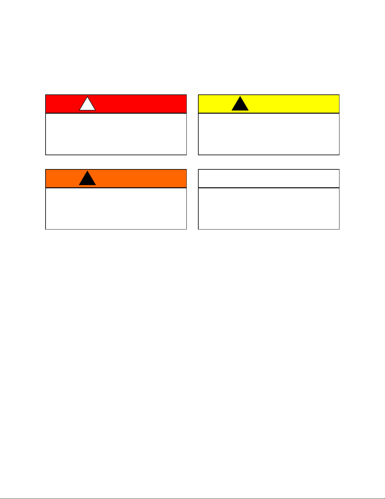
You will find the safety alerts DANGER, WARNING, CAUTION or IMPORTANT used throughout this
manual. Their meaning is listed below:
This is the highest level statement. Failure to
follow the listed instructions will most likely
result in severe injury or death.
This is a statement of serious hazard. Failure
to follow the listed instructions could place
the individual at risk of serious injury or
death.
DO NOT OPERATE THIS PRODUCT UNTIL YOU HAVE READ AND UNDERSTAND THE SAFETY
PRACTICES, WARNINGS AND OPERATING INSTRUCTIONS CONTAINED WITHIN THIS MANUAL.
IMPROPER USE OF THE LOCK & LOAD VEHICLE RESTRAINT COULD RESULT IN SERIOUS
INJURY OR DEATH.
If the Lock & Load vehicle restraint does not operate properly using the procedures in this manual, BE
CERTAIN TO CHOCK THE VEHICLE WHEELS BEFORE LOADING OR UNLOADING. Contact NOVA
or your local representative for service.
DANGER
!
WARNING
!
The statements used with this level of
warning deal with a safe operating
procedure. If the procedure is ignored the
possibility of personal injury may exist.
IMPORTANT is used to draw attention to a
procedure that needs to be followed
to prevent machine damage.
CAUTION
!
IMPORTANT
3 NOVA Lock & LoadTM Owner’s Manual
Page 4
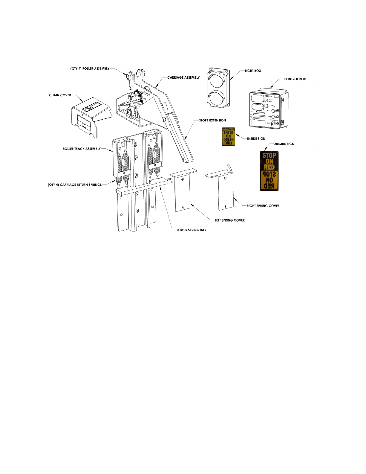
COMPONENTS DESCRIPTION
Figure A—Lock & Load Components Description
4
NOVA Lock & LoadTM Owner’s Manual
Page 5
OPERATING PROCEDURE
Before loading or unloading a vehicle at
your loading dock while using a Lock & Load
vehicle restraint, always visually inspect to
be sure that the restraint is engaged with the
Rear Impact Guard (RIG). If the restraint is
still not engaged after backing the trailer
firmly against the dock bumpers, secure the
trailer by other means.
Be sure that the area around the RIG
assembly is clear of obstructions.
Always operate the Lock & Load vehicle
restraint from the top of the dock.
Inspect all restraint lights daily to make
certain they work properly.
Perform maintenance on restraints in
accordance with Maintenance on page 11 of
this manual.
Lock & Load vehicle restraints should be
operated only by authorized personnel who
have read and understand the Owner’s
Manual.
If you have questions, Call your local
representative or NOVA at (800) 236-7325.
FAILURE TO FOLLOW THESE PROCEDURES
COULD RESULT IN SERIOUS INJURY OR
DEATH.
WARNING
!
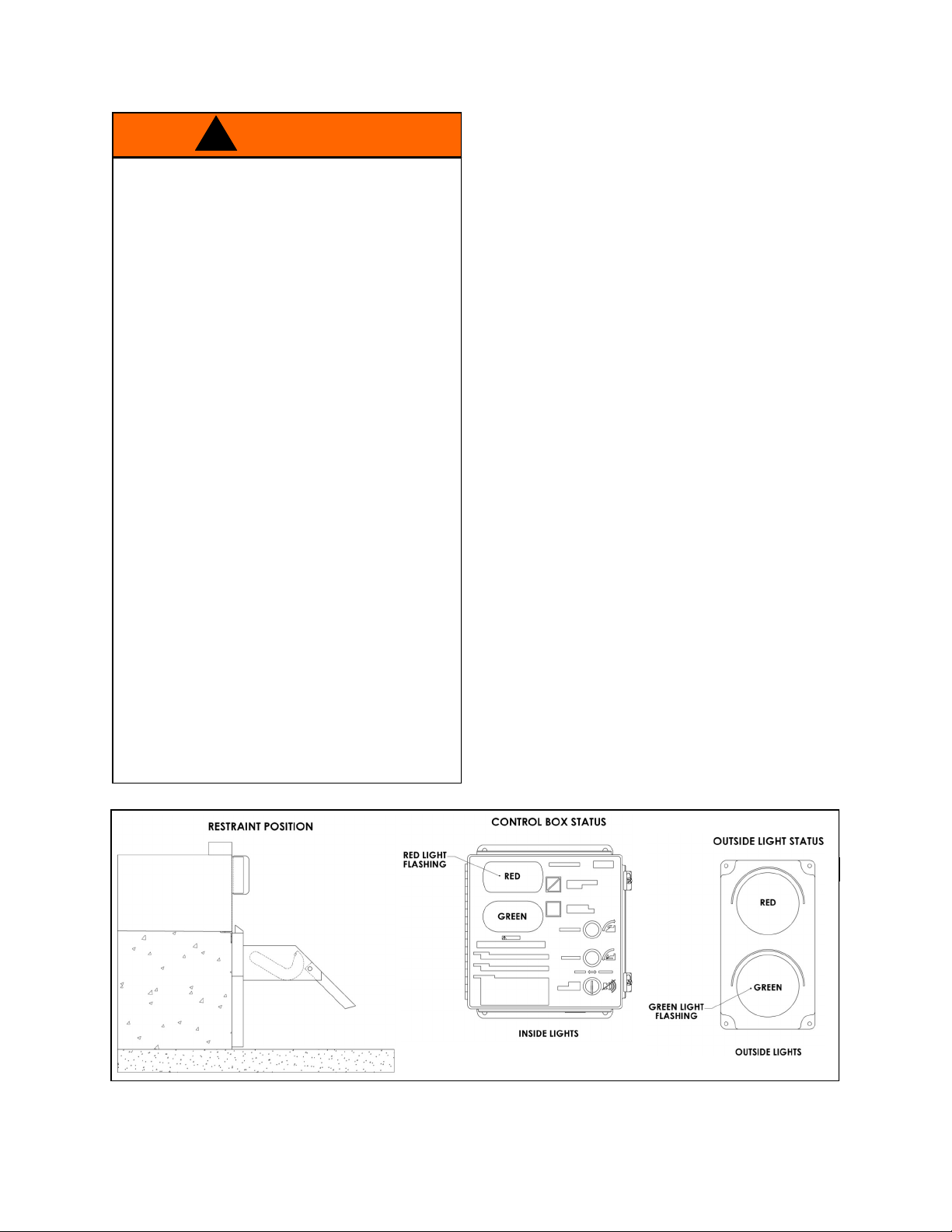
Stored Position / Restraint UNLOCKED
Hook is in the STORED position. Inside light is
flashing red alerting forklift operator unsafe
condition exists. Outside light is flashing green
alerting truck driver it is safe to back in.
Refer to Figure B.
FIGURE B—STORED POSITION
NOVA Lock & LoadTM Owner’s Manual 5
Page 6
OPERATING PROCEDURE continued
RESTRAIN Button Pressed Restraint ENGAGING
Trailer has backed into loading dock and is
parked firmly against dock bumpers. Hook
rotates from stored position to engage RIG.
Outside light is flashing red alerting truck driver
not to move. Refer to Figure C.
If horn sounds, proceed to FAULT, otherwise
proceed to Restraint ENGAGED.
If trailer can not be restrained due to a lift
gate or other obstruction that could become
damaged, proceed to OVERRIDE.
CAUTION
!
FIGURE C—RESTRAINT LOCKING
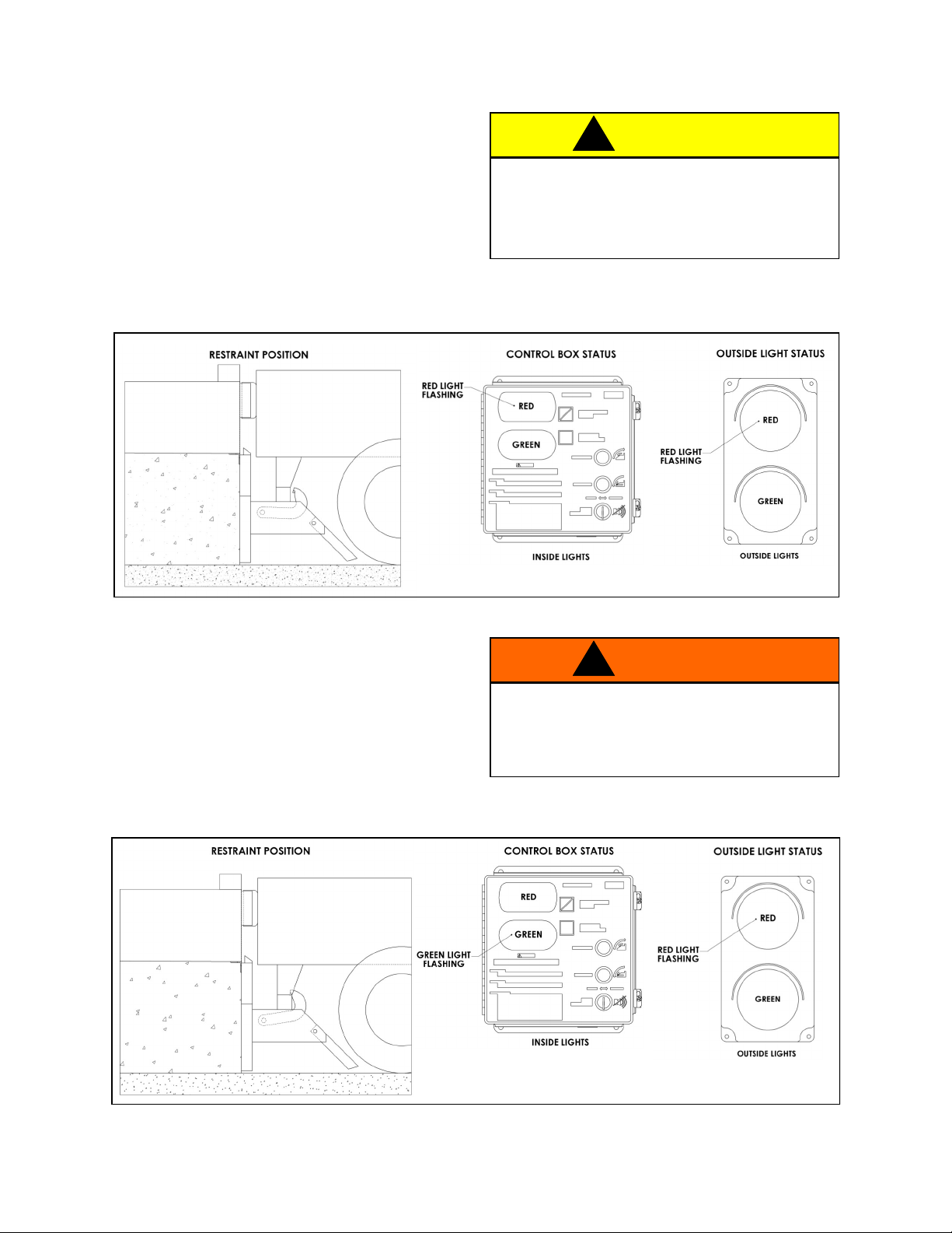
Restraint ENGAGED
Once the RIG is engaged by the hook, an
ENGAGED condition exists. Inside light is flashing green alerting the forklift operator a safe condition exists. Outside light is flashing red alerting
truck driver not to move. Refer to Figure D.
If during loading/unloading the inside light turns
red and the horn sounds, press RESTRAIN
button to secure the RIG.
Visually inspect to ensure that the Lock &
Load vehicle restraint hook securely engages
the RIG of the trailer before operating the
dock leveler.
WARNING
!
6
FIGURE D—RESTRAINT LOCKED
NOVA Lock & LoadTM Owner’s Manual
Page 7
OPERATING PROCEDURE continued
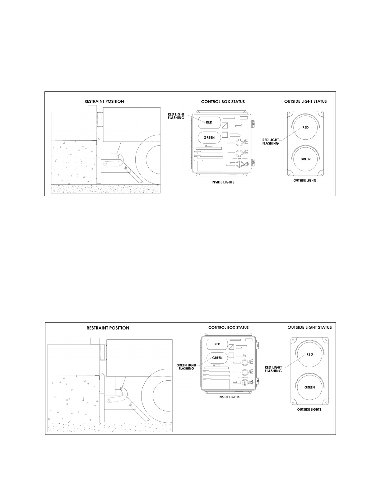
RELEASE Button PressedRestraint DISENGAGING
Hook travels from the ENGAGED position to the
STORED position. Outside light is flashing red
alerting truck driver not to move. Refer to Figure E.
FIGURE E—RESTRAINT UNLOCKING
FAULT from ENGAGING State
Hook cannot engage the RIG. This could be due
to a RIG that is located too far toward the rear
axle, bent, obstructed or missing. Inside light is
flashing red and horn is pulsing, alerting the forklift operator that the trailer is not locked. Outside
light is flashing red alerting the truck driver not to
move. See Figure F.
If the trailer is parked firmly against the dock
bumpers proceed to HORN OVERRIDE. If not,
press RELEASE to clear the fault, have trailer
back up and repeat Restraint ENGAGING.
NOVA Lock & LoadTM Owner’s Manual
FIGURE F—FAULT STATE
7
Page 8
OPERATING PROCEDURE continued
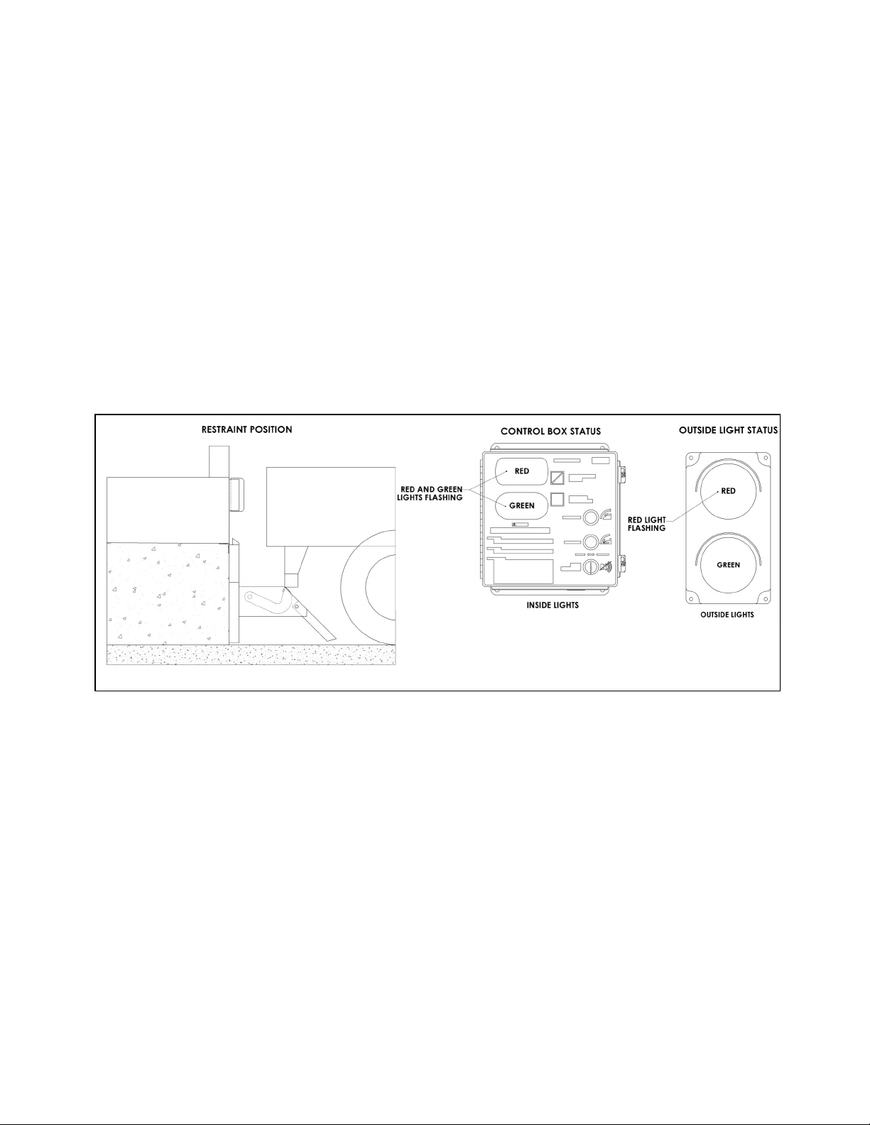
HORN OVER-RIDE State, KEY
SWITCH TURNED TO OVER-RIDE
after Securing Trailer by Alternate
Means
An alternate means of securing the truck must be
used (e.g. wheel chocks) if the hook can not
capture the RIG. Inside lights are flashing red
and green alerting the forklift operator the trailer
is secured by other means. Outside light is
flashing red alerting the truck driver not to move.
See Figure G.
To return to STORED, turn the HORN OVERRIDE key and press the RELEASE button.
FIGURE G—HORN OVER-RIDE STATE
NOVA Lock & LoadTM Owner’s Manual 8
Page 9

ROUTINE MAINTENANCE
When working with electrical or electronic
controls, make sure that the power source
has been locked out and tagged according to
OSHA regulations and approved local
electrical codes.
Post safety warnings and barricade work area, at dock level and at ground level, to prevent unauthorized use of the dock.
Safe operation of the Lock & Load truck
restraint requires all lights and the
horn to be working properly. DO NOT use
Lock & Load vehicle restraint if parts are
broken or missing.
Use lifting device (e.g. crane, jack) when
lifting carriage (approx. 110 lbs.). Lifting by
hand may cause back injury.
Maintenance may be required more
frequently at loading docks exposed to harsh
environments (extreme climates, corrosive
chemicals, frequency of usage, etc.). If these
conditions exist, consult NOVA for
accelerated maintenance requirements.
NOTE: If a leveler is installed at the Lock & Load
vehicle restraint location, it may be necessary to
raise the leveler before performing maintenance.
Raise the leveler, insert and secure the maintenance strut, and LOCKOUT/TAGOUT the power
source.
DANGER
!
WARNING
!
CAUTION
!
IMPORTANT
DAILY
Remove debris around Lock & Load vehicle
Verify that restraint operates smoothly and
Replace damaged or missing light bulbs and
Repair, remount, or replace outside and
Inspect dock bumpers. Missing bumpers must
180 DAYS
Perform all Daily maintenance.
Grease rollers at fittings located on the top
Verify brake torque is greater than 500 in-lbs,
Inspect the outside electrical connections
Check that all concrete anchor bolts are
Perform operational test after all maintenance
Inspect dock bumpers. Four inches (4") of
360 DAYS
Perform all Daily and 180 Day maintenance.
Check and tighten, if necessary, motor drive
Lube chain using chain lube.
Lubricate limit switch mounting bracket
restraint.
inside, outside lights and horn are working.
lenses.
inside signs and labels as required.
be replaced.
and bottom axle with a synthetic oil-base moly grease with a temperature range of
–40° to 170° F.
and less than 700 in-lbs at the hook shaft,
rotating the hook from ENGAGED to
STORED.
(junction box, conduit, power harness) and
outside communication light. Loose or
damaged components must be repaired or
replaced.
torqued to 100 ft-lbs.
repairs and adjustments are complete.
protection is required. Worn, torn, loose or
missing bumpers must be replaced.
chain. To tighten see Figure H, page 10.
between drive sprocket and cam with a
synthetic oil-base moly grease with a
temperature range of –40° to 170° F .
NOVA Lock & LoadTM Owner’s Manual
9
Page 10

ROUTINE MAINTENANCE
DRIVE CHAIN ADJUSTMENT
Inspect the drive chain periodically for dirt and
chain slack. Open the motor enclosure and clean
the chain with solvent. After cleaning, spray with a
high quality chain spray type lubricant.
The drive chain should not have more than 1/4"
slack. Refer to Figure H. To tighten chain:
Open motor enclosure and loosen the four (4)
motor mounting bolts.
Pry the motor assembly forward, in the
slotted holes, until the chain is tight with proper alignment between sprockets.
Hold in this position and tighten the four (4)
motor mounting bolts to 75 in-lbs.
When working with electrical or electronic
controls, make sure that the power source
has been locked out and tagged according to
OSHA regulations and approved local
electrical codes.
DANGER
!
BRAKE TORQUE ADJUSTMENT
(Refer to Figure H.)
Loosen brake adjuster locknut while holding
the adjuster screw to prevent inadvertent
adjustment.
Turn adjuster screw clockwise to increase
brake torque as needed.
Tighten adjuster locknut while holding the
adjuster screw to prevent inadvertent
adjustment.
Verify brake torque is in the range of 500 to
700 in-lbs at the hook shaft; readjust as required.
10
FIGURE H—MAINTENANCE AND LUBRICATION
NOVA Lock & LoadTM Owner’s Manual
Page 11

TROUBLESHOOTING
PROBLEM PROBABLE CAUSE RESOLUTION
Lock & Load vehicle restraint
lights do not flash and the
hook does not raise.
Lock & Load vehicle restraint
lights are flashing, but the
hook does not raise or lower to
full extent.
Lock & Load vehicle restraint
is operational, but hook drops
causing lights to change and/
or horn to sound while trailer is
being serviced.
Lock & Load vehicle restraint
is operational but all lights are
out.
Power source malfunction.
Incorrect wiring.
Chain is loose or broken.
Low incoming voltage.
Drive motor defective.
Incorrect wiring.
Verify brake torque.
Drive motor defective
Bulbs burnt out, loose or missing.
Incorrect wiring.
Check power source, including facility
circuit breaker and 1A fuse. and
circuit breaker on power module.
Verify wiring per Electrical Schematic,
Figure K page 14.
Adjust or replace as required.
Verify incoming voltage at L1 and L2
is a minimum of 110V. Do not power
off a control transformer from other
equipment unless properly sized for
load.
Check motor. Repair or replace as
needed.
Verify wiring per Electrical Schematic,
Figure K page 14.
If brake torque is less than 500 in lb or
chain is loose or broken, adjust or
replace as required.
Check motor. Repair or replace as
needed.
Check all bulbs and replace as re-
quired.
Verify wiring per Electrical Schematic,
Figure K page 14.
Lock & Load vehicle restraint
horn does not sound but hook
and lights are operational.
Lock & Load vehicle restraint
hook is in stored position with
an inside green light.
Lock & Load vehicle restraint
carriage does not return to a
full up position
Horn is defective.
Incorrect wiring.
Power horn using 12V DC power. If
horn does not sound, replace as required.
Verify wiring per Electrical Schematic,
Figure K page 14.
Incorrect wiring. Verify wiring of SW1 and SW2 at the
control box and outside junction box.
Carriage binding in track.
Damaged roller track plate.
Broken or weak springs.
Check to see if roller track plate is
clean and rollers are clean, full of debris and lubricated. Use only approved grease to lubricate rollers.
Verify that the roller track plate is
straight and not damaged.
Remove spring cover and replace as
required
NOVA Lock & LoadTM Owner’s Manual
11
Page 12

TROUBLESHOOTING CONTINUED
LIMIT SWITCH TEST PROCEDURE
Set multimeter to “RX1” scale for “Continuity
Test”.
Attach multimeter leads to pins “B” and “C” of
limit switch connector. You should have:
- plunger released - no meter reading.
- plunger depressed - a “Full Scale” meter
reading.
NOTE: The green (ground) wire of the limit switch
does not have to be tested. A continuity test lamp
may be used instead of a multimeter.
FIGURE I—LIMIT SWITCH AND HOOK POSITION CHART
12
NOVA Lock & LoadTM Owner’s Manual
Page 13

CONTROL HARNESS
NOVA Lock & LoadTM Owner’s Manual
FIGURE J—CONTROL HARNESS
13
Page 14

ELECTRICAL SCHEMATIC
WIRING PROVIDED BY OTHERS
WIRING PROVIDED BY NOVA TECHNOLOGY
14
LOCK MOTOR
1/10 HP
3.5 FLA
MOTOR HAS AUTOMATIC
THERMAL OVERLOAD
FIGURE K—ELECTRICAL SCHEMATIC
NOVA Lock & LoadTM Owner’s Manual
Page 15

OUTSIDE LIGHT BOX WIRING
FIGURE L—OUTSIDE LIGHT BOX WIRING
NOVA Lock & LoadTM Owner’s Manual
15
Page 16

CARRIAGE ASSEMBLY DRAWING
PARTS
FIGURE M —CARRIAGE ASSEMBLY
CARRIAGE ASSEMBLY PARTS LIST
ITEM NO. PART NUMBER DESCRIPTION
1 MF2-015-000 3/8"-16 X 1 1/2" HH CAP SCREW
2 MF2-061-000 SNAP RING
3 MF2-047-000 ROLLER ASSEMBLY
4 MF2-034-000 3/4" CONDUIT NIPPLE
5 MF2-038-000 LIMIT SWITCH, LS1
6 MF2-039-000 LIMIT SWITCH, LS2
7 MF2-094-000 CAM DECAL
8 MF2-028-000 CAM
9 MF2-024-000 LIMIT SWITCH MOUNTING PLATE
10 MF2-042-000 CHAIN COVER
QTY.
2
1
4
1
1
1
1
1
1
1
16
NOVA Lock & LoadTM Owner’s Manual
Page 17

PARTS continued
CARRIAGE ASSEMBLY PARTS LIST continued
ITEM NO. PART NUMBER DESCRIPTION QTY.
11 MF2-026-000 7/16”-14 SERRATED FLANGE LOCK NUT 2
12 MF2-016-000 3/8"-16 SERRATED FLANGE WHIZ NUT 8
13 MF2-041-000 1/4"-20 X 1 1/2" SOCKET HEAD CAP SCREW 2
14 MF2-018-000 1 3/4" OD, 1 1/4" ID, 1/8" THK, MACHINERY BUSHING 2
15 MF2-040-000 1/4" LOCK WASHER 2
16 MF2-095-000 NO STEP DECAL 1
17 MF2-021-000 1/4" X 1/4" X 1 1/4" HOOK KEY 1
18 MF2-023-000 1/4" X 1/4" X 1" KEY, SPROCKET & CAM 2
19 MF2-020-000 HOOK SHAFT 1
20 MF2-037-000 3/4" CONDUIT LOCK NUT 2
21 MF2-022-000 HOOK DRIVE SPROCKET W/SET SCREW 1
22 MF2-019-000 5/16"-18 X 1/2" SK SET SCREW 1
23 MF2-014-000 3/8"-16 X 1" CARRIAGE BOLT 6
24 MF2-117-000 5/16”-18 X 5/8” FLANGE HEAD SCREW 4
25 MF2-033-000 CORD GRIP 1
26 MF2-003-000 STRAIGHT HOOK 1
27 MF2-004-000 CARRIAGE WELDMENT 1
28 MF2-005-000 WIRE HARNESS 1
29 MF2-017-000 LOCK & LOAD BEARING ASSEMBLY 2
30 MF2-017-002 SET SCREW 4
31 MF2-064-000 "LOCK & LOAD" HORIZONTAL DECAL 1
32 MF2-066-000 5/16"-18 X 5/8" SET SCREW 1
33 MF2-068-000 SERIAL NUMBER DECAL 1
34 MF2-080-000 "LOCK & LOAD" LARGE HORIZONTAL DECAL 1
35 MF2-107-000 CHAIN 1
36 MF2-110-000 MF2 MOTOR ASSEMBLY 1
37 MF2-027-000 7/16-14 NYLOCK NUT 1
38 MF2-013-000 GREASE FITTING 2
NOVA Lock & LoadTM Owner’s Manual
17
Page 18

PARTS continued
ROLLER TRACK ASSEMBLY DRAWING and PARTS LIST
FIGURE N—ROLLER TRACK ASSEMBLY
ITEM NO. PART NUMBER DESCRIPTION QTY.
1 MF2-052-000 SPRING COVER RIGHT HAND 1
2 MF2-048-000 ROLLER TRACK 1
3 MF2-049-000 5/16"-18 CAGE NUT 4
4 MF2-050-000 EXTENSION SPRING 4
5 MF2-054-000 5/8" X 4" CONCRETE ANCHOR 15
6 MF2-051-000 LEFT SPRING COVER 1
7 MF2-060-000 5/16"-18 X 1 1/4" FLAT HEAD SOCKET SCREW 4
18
NOVA Lock & LoadTM Owner’s Manual
Page 19

PARTS continued
SLOPE EXTENSION DRAWING AND PARTS LIST
FIGURE O—SLOPE EXTENSION ASSEMBLY
ITEM NO. PART NUMBER DESCRIPTION QTY.
1 MF2-045-000 1" X 18 GAUGE FLAT WASHER 2
2 MF2-046-000 COTTER PIN 1
3 MF2-044-000 SLOPE EXTENSION PIVOT PIN 1
4 MF2-043-000 SPRING MOUNTING PLATE ASSEMBLY 1
5 MF2-026-000 7/16"-14 SERRATED FLANGE LOCK NUT 2
6 MF2-002-000 SLOPE EXTENSION 1
7 MF2-007-000 LOCK & LOAD CARRIAGE ASSEMBLY 1
8 MF2-132-000 ROLLER SLOPE EXTENSION 1
9 MF2-143-000 5/8” X 3” CLEVIS PIN 1
10 MF2-142-000 COTTER PIN 1
11 MF2-130-000 5/8” SAE FLAT WASHER 1
12 MF2-136-000 ROLLER ASSEMBLY 1
NOVA Lock & LoadTM Owner’s Manual
19
Page 20

ELECTRICAL PARTS
PARTS continued
20
FIGURE P —ELECTRICAL PARTS
NOVA Lock & LoadTM Owner’s Manual
Page 21

PARTS continued
ELECTRICAL REPLACEMENT PARTS LIST
ITEM NO. PART NUMBER DESCRIPTION
1 MF2-082-000 TIMER
2 MF2-083-000 FLASHER
3 MF2-084-000 TRANSFORMER
4 MF2-085-001 RED RECTANGULAR LENS
5 MF2-085-002 RECTANGLE BASE
6 MF2-085-003 RED LED WEDGE
7 MF2-086-001 GREEN OVAL LENS
8 MF2-086-002 OVAL BASE
9 MF2-086-003 GREEN LED WEDGE
10 MF2-087-000 OUTSIDE RED LED LIGHT MODULE
11 MF2-088-000 OUTSIDE GREEN LED LIGHT MODULE
12 MF2-089-001 GREEN PUSH BUTTON
13 MF2-089-002 NO CONTACT
14 MF2-089-003 CONTACT BASE
15 MF2-090-001 YELLOW PUSH BUTTON
16 MF2-091-001 KEY SWITCH
17 MF2-091-002 NC CONTACT
18 MF2-091-003 NO CONTACT
19 MF2-091-004 CONTACT BASE
20 MF2-092-000 KEY
21 MF2-156-000 FUSE
22 MF2-157-000 FUSE
23 MF2-158-000 FUSE
QTY.
1
1
1
1
1
2
1
1
2
1
1
1
2
2
1
1
1
1
1
1
1
1
1
NOVA Lock & LoadTM Owner’s Manual
21
Page 22

MISCELLANEOUS PARTS
PARTS continued
FIGURE Q —MISCELLANEOUS PARTS
MISCELLANEOUS REPLACEMENT PARTS LIST
ITEM NO. PART NUMBER DESCRIPTION QTY.
1 MF2-011-000 CONTROL BOX 1
2 MF2-012-000 OWNERS MANUAL 1
3 MF2-057-000 CAUTION SIGN 1
4 MF2-056-000 STOP ON RED SIGN 1
5 MF2-055-000 OUTSIDE TRUCK LIGHT ASSEMBLY 1
6 MF2-093-000 INSTALLATION MANUAL 1
22
NOVA Lock & LoadTM Owner’s Manual
Page 23

WARRANTY
NOVA STANDARD PRODUCT WARRANTY
Nova Technology International, LLC (“Nova”) warrants that its products will be free from defects in
design, materials and workmanship for a period of one (1) year from the date of shipment. All claims for
breach of this warranty must be made within 30 days after the defect is or can with reasonable care, be
detected. In no event shall any claim be made more than 30 days after this warranty has expired. In
order to be entitled to the benefits of this warranty, the product must have been properly installed,
maintained and operated in accordance with all manufacturer’s recommendations and/or specified
design parameters and not otherwise have been subject to abuse, misuse, misapplication, acts of
nature, overloading, unauthorized repair or modification, application in a corrosive environment or lack of
maintenance. Periodic lubrication, adjustment and inspection in accordance with all manufacturers’
recommendations are the sole responsibility of the Owner/User.
In the event of a defect, as determined by Nova, covered by this warranty, Nova shall remedy such
defect by repairing or replacing any defective equipment or parts, bearing the cost for the parts, labor
and transportation. This shall be exclusive remedy for all claims whether based on contract, negligence
or strict liability.
PRODUCT SPECIFIC WARRANTY
Lock & Load Vehicle Restraint
In addition to the “Standard Product Warranty” provided with all Nova Products, Nova guarantees
materials, components and workmanship to be free of defects for the following extended periods:
Extended 2-year General Warranty– For a period of two (2) years from date of shipment, this
warranty specifically applies to: the roller track assembly, carriage assembly, and control box only.
Extended 5-year Structural Warranty – For a period of five (5) years from the date of shipment,
product will carry a prorated structural warranty. This warranty specifically applies to: the roller
track, carriage weldment, chain cover, straight hook, and lower spring bar only.
NOT COVERED UNDER WARRANTY
Routine maintenance, lubrication, adjustments, including initial field set-up.
Repairs required as a result of failure to follow routine maintenance procedures specified in the
owner’s manual, abuse, accident, willful damage, neglect, improper installation, submersion, or
shipping damage.
WARRANTY LIMITATIONS
The above warranties are in lieu of any other warranties, whether expressed or implied, including but not
limited to and implied warranty of merchantability for a particular purpose. Nova and its subsidiaries
shall not in any event be liable to anyone, including third parties, for incidental, consequential or special
damages of any kind including but not limited to, breach of warranty, loss of use, loss of profit,
interruption of business or loss of goodwill.
NOVA Lock & LoadTM Owner’s Manual
23
Page 24

N90W14507 Commerce Drive Menomonee Falls, WI 53051
Phone 262-502-1591 | 800-236-7325 | fax 262-502-1511
www.novalocks.com
© 2011 Nova Technology International, LLC
 Loading...