

Nova FPA-0-2124-27, FPA-0-2124-28, FPA-0-2124, FPA-0-2124-30, FPA-0-2124-33 Assembly Manual
...Page 1
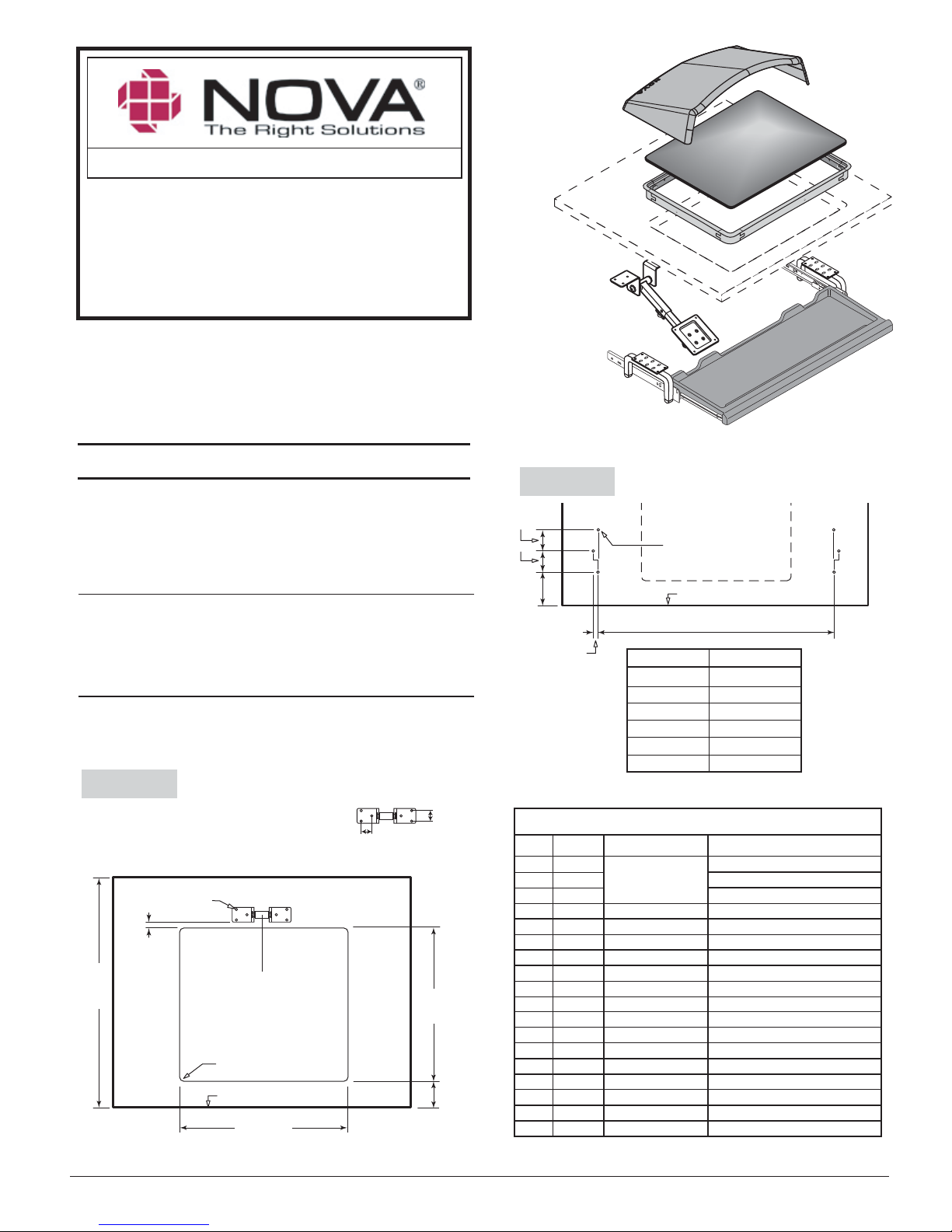
Includes
Flat panel display arm,
keyboard drawer,
visor, glass &
trim ring
The natural way to look at a computer™
Flat Panel Display Arm
Retrofit Kit
Assembly Instructions
Model #
FPA-0-2124
Widescreen Format
-27, -28, -30, -33, -34
The arm ships with two VESA plates. Determine the one you need by holding VESA
plates up to the attachment holes on the back of the monitor. Select the one where
all four holes line up with the VESA plate holes.
Step 1.
Cut opening for viewport. (Figure 1A). Prepare surface for keyboard
drawer (Figure 1B).
21/2"
(64 mm)
"
4
(102 mm)
1-1/4"
(
Offset 32mm)
(Typ.)
Step 2.
Using the hole pattern on the desk mount extension tube (B1) as a
template, locate and drill holes (Figure 1A). Note drill size and hole depth!
Figure 1B -
Figure 1A
UNDERSIDE OF TOP CLEARANCE
27 1/4"(692 mm) Minimum Clearance Depth Of Worksurface
3
/16" Dia.
5
/8" Deep
6 Places
1
/4"
27-1/4"
mm)
(692
P.O. Box 725 • 421 W. Industrial Avenue • Effingham, Illinois 62401 • Phone: (800) 730-6682 • Fax: (800) 940-6682 • info@novasolutionsinc.com • www.novadesk.com
IIR018Bb FPA-0-2124 Widescreen Asy. Instr. 05/20/13 © Nova Solutions, Inc. 2013
Center on
viewport opening
1
/2"(12.7 mm) R.
All corners
FRONT EDGE
24-1/4"
(616 mm)
DESK MOUNT EXT. TUBE
1.26"
(32
mm)
1.26"(32 mm)
21-1/4"
(540 mm)
3"
(76 mm)
Patents pending.
QTY REF # ITEM # DESCRIPTION
1 A1 75 mm *VESA plate
1 A2 100 mm *VESA plate
1 B Desk bracket
1 C
10 D 1412APPBO Screw, #14 x 3/4"
1 F 20060126
1 G 20060127
1 H Varies Keyboard drawer
1 J 5081073 Viewport glass
2 L 50900032 Screw - #14 x 1-1/2"
4 M 6N50TXPZ Security screw #6 x 5/8"
4 N 50900034 Trim ring corner
2 O1 50900037 18” Trim ring straight (C)
2 O2 50900038 21” Trim ring straight (D)
1 P 5081062 Visor
2 Q FR2121/Clip Locking tab
4 S 10628-03819 Screw, Black, 4mm x 0.7 x 8
*VESA 75/100 Standard
Hole pattern for keyboard drawer
3
/16" Dia.
5
/8" Deep
6 Places
FRONT EDGE
A
KB drawer size
27"
28"
30"
33"
34"
Dimension A
2219/32"(574 mm)24"
5
/16"(643 mm)
25
1
/8"(664 mm)
26
1
/16"(713 mm)
28
1
/4"(794 mm)
31
321/8"(816 mm)
PACKING LIST
FPA-8-2006
924B-2520-0-50A
Wing nut
Keyboard hanger w/ glide - left
Keyboard hanger w/ glide - right
Page 1
Page 2
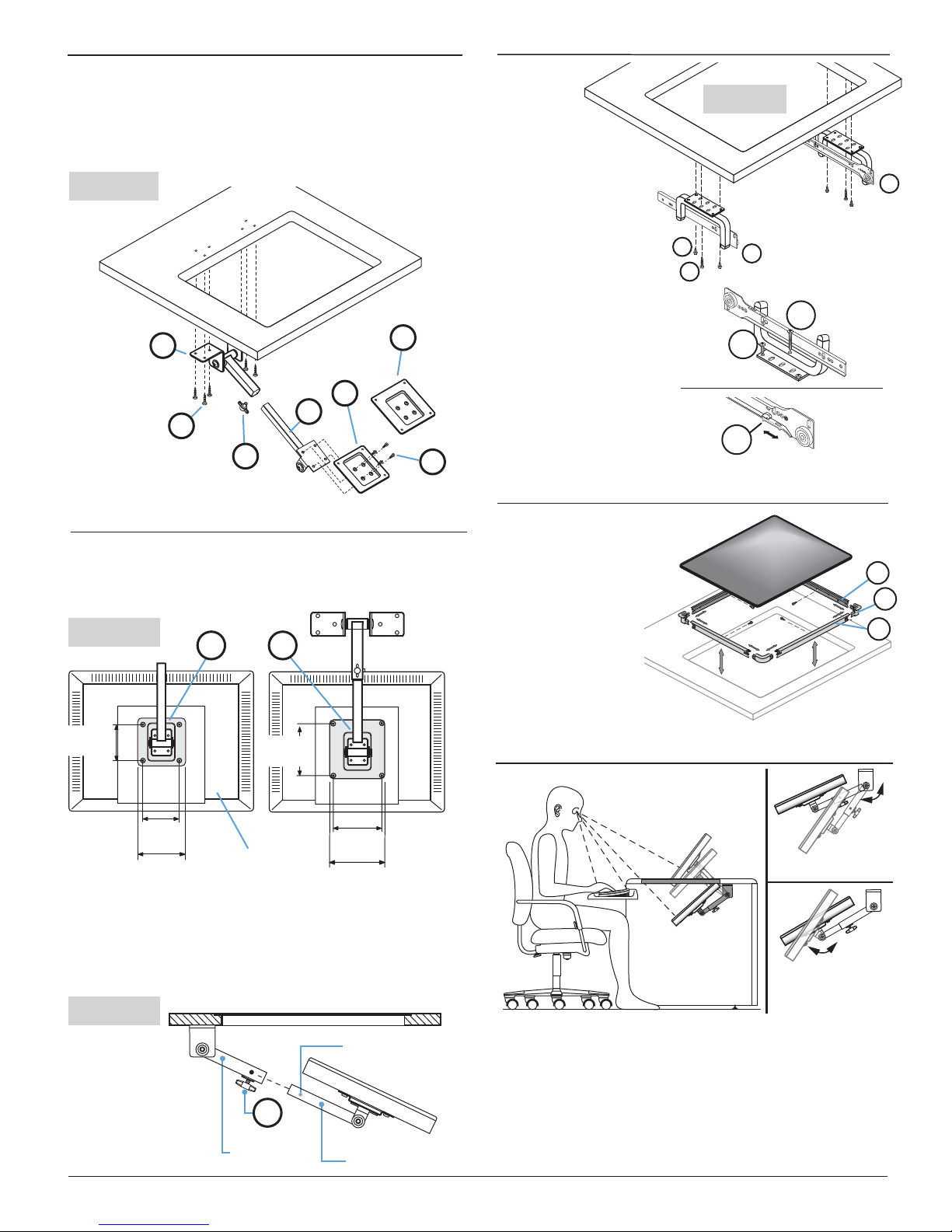
Step 3.
Step 5
Align holes in desk mount extension tube (B1) with holes in
worksurface (Figure 2). Attach using screws (D).
Using 4 screws (S),
attach VESA plate (A1 or A2) to VESA plate extension tube (B2).
WARNING: Removing the set screws or oiling the joints could cause
the flat panel display to fall and void the warranty.
Figure 2
Back edge of cut-out
B1
A1
B2
Step 4.
D
C
Attach flat panel display to VESA plate
Remove flat panel display base. Attach flat panel display to VESA
plate (using screws located on the back of your flat panel display,
supplied by the manufacturer). See Figure 3.
Figure 3
A1
A2
A2
S
Attach
keyboard
Figure 5
hangers (F,G, Figure
5) to underside of
worksurface with screws
(D, L). Insert locking tab
(R) then pull it forward to
lock in place.
IMPORTANT:
D
L
The longer screws
F
L
(L) pass through the tubular
section of the keyboard
D
hanger. That allows the
assembly to be leveled by
loosening or tightening the
screws.
Q
Step 6. Install trim ring & viewport glass
Snap trim ring
pieces (N, O1, O2) together.
Insert into viewport cutout
and attach with screws
(M). Carefully insert
viewport glass (J) into
trim ring. Slide
keyboard tray into
glides.
G
O2
N
O1
75 mm
(2-
15
/16")
75 mm
15
/16")
(2-
3-3/4"
Display
100 mm
15
(3-
/
16
")
100 mm
15
(3-
/
16
")
7
4-
/
16
"
Depress silver spring pin on VESA plate extension tube and slide it
into the desk mount extension tube. Tighten wing nut (C, Figure 4).
See "Monitor Angle" for adjustment guidance.
When installing some
Apple® flat panel displays, a VESA Adapter (Model #50-8-4100) may
be necessary. Contact Customer Support for more information.
Figure 4
viewport cut-out
Silver spring pin
C
Desk mount
Extension tube
IIR018b FPA-0-2124 Widescreen Asy. Instr. © Nova Solutions, Inc. 2013
VESA plate
Extension tube
Monitor Angle
270°
320°
VESA Plate
Adjustment
1. Locate screen as high as possible without raising glass.
2. Aim screen slightly above user’s eyes. (Bottom of screen should be
closer to eyes than top of screen.)
3. Preferred location is with top edge of flat panel display at back
edge of glass.
4. For semi-recessed positions, remove viewport glass and
raise flat panel display.
Page 2
 Loading...