

Nova Dock Sentinel DG-109-000, Dock Sentinel DG-048-000, Dock Sentinel DG-108-000 Installation Manual
Page 1
Safety Gate
Models DG-048-000, DG-108-000, DG-109-000
Installation Manual
© 2013 Nova Technology International, LLC
MADE IN U.S.A.
INST-DG-001 October 2013
Page 2
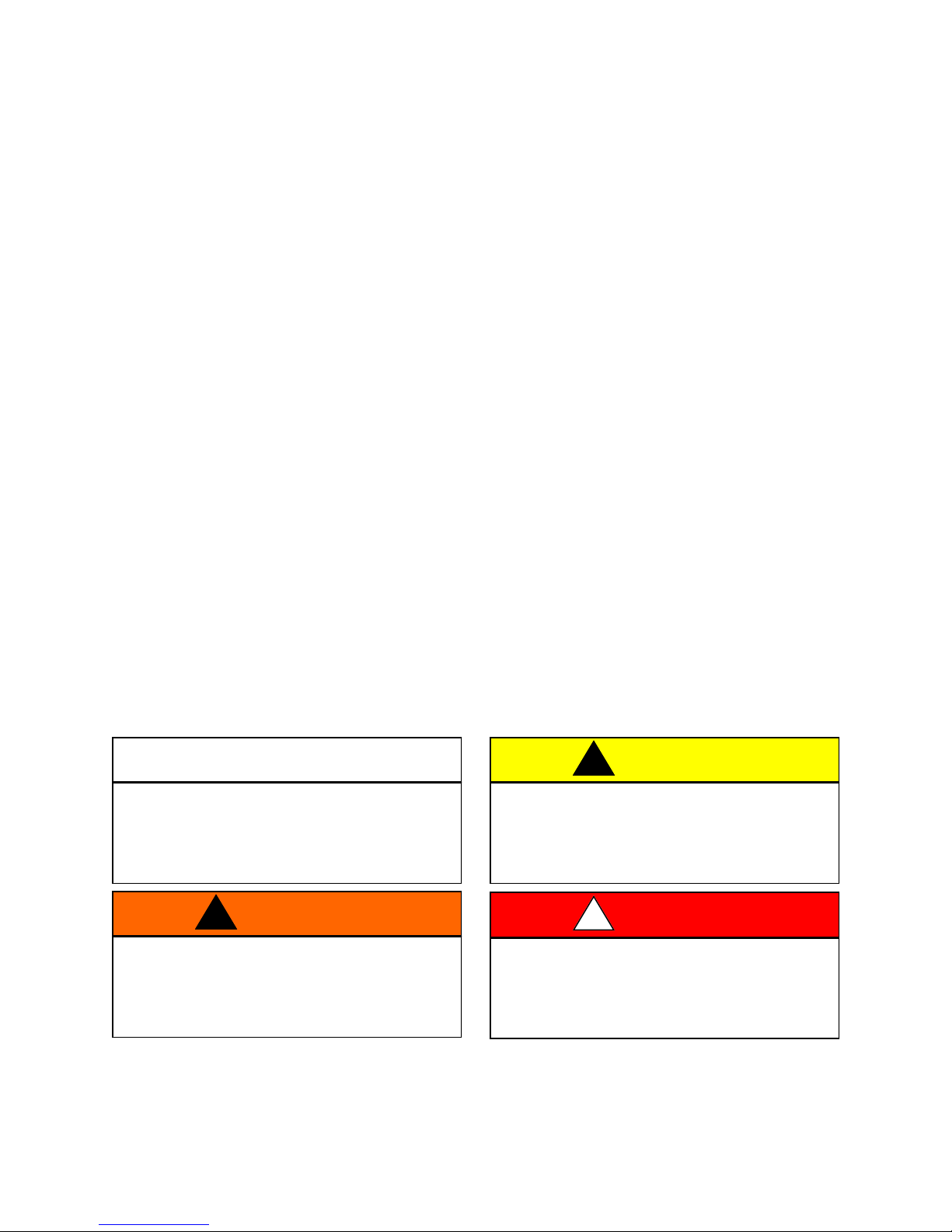
TABLE OF CONTENTS
Page
PARTS IDENTIFICATION 3
INSTALLATION TOOLS REQUIRED 3
INSTALLATION STEP 1: ALIGNING THE DOCK GATE 4
INSTALLATION STEP 2: BOLTING THE GATE TO THE FLOOR 5
INSTALLATION STEP 3: INSTALLING THE UPPER BARRIER 6
INSTALLATION STEP 4: CONNECTING THE TIE RODS 7
INSTALLATION STEP 5: FINAL CHECK 7
OPERATING INSTRUCTIONS 8
GATE ADJUSTMENTS
LOWER BARRIER LEVEL ADJUSTMENT 9
LIFTING FORCE ADJUSTMENT 10
BARRIER STABILIZER ADJUSTMENT 11
PARTS LISTS
LEFT SIDE MAIN ASSEMBLY 12
LEFT SIDE SECONDARY ASSEMBLY 14
POWER PACK ASSEMBLIES 16
NOTES 17
RIGHT SIDE MAIN ASSEMBLY 18
RIGHT SIDE SECONDARY ASSEMBLY 20
LATCH ASSEMBLIES 22
ANCHORS and DECALS 23
WARRANTY 24
IMPORTANT is used to draw attention to a
procedure that needs to be followed
to prevent machine damage.
This is a statement of serious hazard. Failure
to follow the listed instructions could place
the individual at risk of serious injury or
death.
IMPORTANT
WARNING
!
The statements used with this level of
warning deal with a safe operating
procedure. If the procedure is ignored the
possibility of personal injury may exist.
This is the highest level statement. Failure to
follow the listed instructions will most likely
result in severe injury or death.
CAUTION
!
DANGER
!
NOVA reserves the right to make product changes without notice and as such this manual may not be
an exact representation of product received.
2
NOVA Dock Sentinel
TM
Installation Manual
Page 3
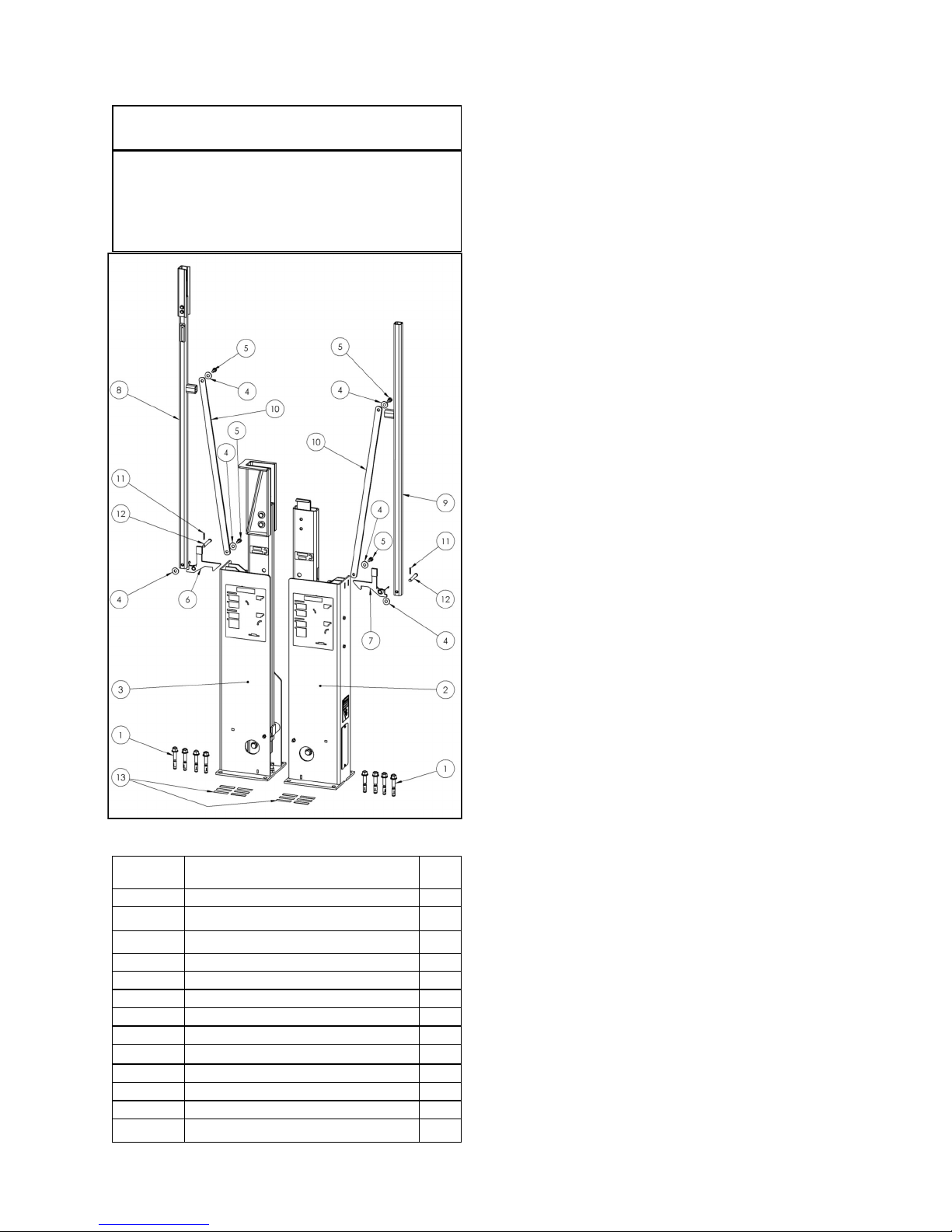
PARTS IDENTIFICATION
IMPORTANT
Before starting installation, verify that all
components and required tools are at hand.
INSTALLATION TOOLS REQUIRED
Tape Measure
Framing Square
Marker
Mason Drill
5/8” Mason Bit
Compressed Air or Vacuum
Torque Wrench (80 ft-lbs)
15/16” Socket / Wrench
Long, large screwdriver or small pry bar
Hammer
Needle Nose Pliers
1/4” Allen Wrench
Level
Shims
Figure 1: Parts Identification
ITEM NO. DESCRIPTION QTY.
1 ANCHOR BOLT 8
2 RIGHT SIDE UPRIGHT ASSEMBLY 1
3 LEFT SIDE UPRIGHT ASSEMBLY 1
4 WASHER 6
5 SHOULDER SCREW 4
6 LEFT LATCH ASSEMBLY 1
7 RIGHT LATCH ASSEMBLY 1
8 LEFT SIDE UPPER BARRIER 1
9 RIGHT SIDE UPPER BARRIER 1
10 TIE ROD 2
11 COTTER PIN 2
12 CLEVIS PIN 2
13 SHIM, FLAT 12
NOVA Dock Sentinel
TM
Installation Manual
3
Page 4
STEP 1: ALIGNING THE DOCK GATE
Read entire manual before installation.
IMPORTANT
1. Ensure dock area is clear of materials and
debris. Sweep floor clean within a 4 foot area
on the door. Debris on floor could make
aligning and mounting uprights difficult and
may affect installation.
Lower barriers are not secure in the uprights
at this point in the installation process —they
can be lowered which could cause the
uprights to tip over unexpectedly. Until the
uprights are fastened to the floor, secure the
barriers into the uprights as necessary.
WARNING
!
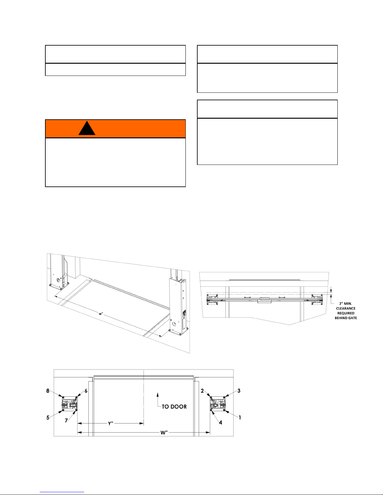
2. Place uprights on the inside of the dock just
outside of the dock door opening as shown in
Figures 2, 2.1 & 3. (NOTE: The uprights
should be placed with decals facing inside the
facility, away from the door. The back edge of
the upright base plate should be a minimum
of 2” from the face of the door.)
Be certain that the uprights are the indicated
distance apart and parallel across the front.
Poor measuring will result in poor alignment.
When you are laying out the positioning of
the uprights, be sure to allow enough
distance from the door tracks to prevent any
interference when you drill holes to fasten
the anchors to the floor.
3. Align the uprights so they are parallel across
from each other and measure exactly W apart
(make sure the front and back are both W apart
and are square with each other). NOTE: The
more accurate you are in this step the more
accurate the installation will be. Be certain
the uprights are centered on the dock door.
See Figures 2 and 3.
IMPORTANT
IMPORTANT
W = 96” - 8’ Gate
W = 102” - 8’-6” Gate
W = 108” - 9’ Gate
Figure 2: Mounting position for uprights
Figure 3: Mounting position for uprights
4
Figure 2.1: Mounting position for uprights
Y = 48” - 8’ Gate
Y = 51” - 8’-6” Gate
Y = 54” - 9’ Gate
NOVA Dock Sentinel
TM
Installation Manual
Page 5
STEP 2: BOLTING THE GATE TO THE FLOOR
Safety glasses must be worn during
1. Drill the first 5/8” hole for the anchor as noted
in Figure 3 (right side upright, front & outside
hole). Drill the hole into the concrete, minimum
of 4 inches.
2. Remove dust and debris from the hole using a
hand pump, compressed air or a vacuum.
3. Check plumb on front and back of upright with
level and shim under the upright as required.
4. Position the washer on the anchor and thread
on the nut. Drive the anchor through the hole
on the upright to a minimum of 3-3/8” deep.
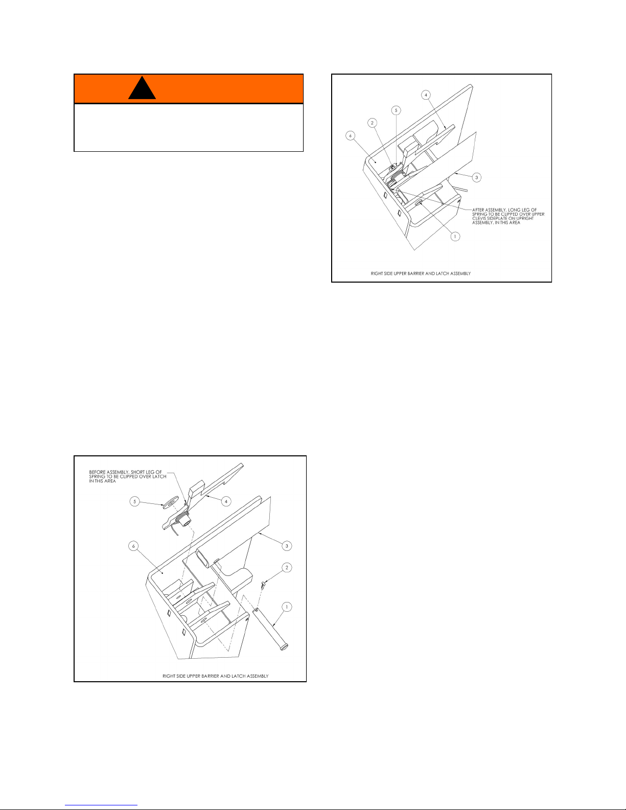
5. Align the right side upper barrier, (item 3,
Figures 4 & 5), into the clevis as shown. Insert
the clevis pin (item 1 below) through the clevis
plates stopping at the second plate.
6. Align the latch assembly (item 4, Figures 4 & 5)
with the clevis pin as shown. Verify spring is
aligned as shown.
7. Push clevis pin fully through latch assembly.
Add washer (item 5, Figures 4 & 5) and install
cotter pin (item 2, Figures 4 & 5).
WARNING
!
this step.
Figure 5
8. Lower gate and confirm barriers are parallel
with door.
9. Drill and anchor holes 2-4 in order as shown in
Figure 3 with the same steps as the first hole.
NOTE: Confirm that the upright is plumb with
level on the front and back and shim as
required prior to securing anchors.
10. While supporting the left upright, lower the left
barrier to confirm alignment and correct
distance to the right hand lower barrier.
11. Drill the fifth 5/8” hole for the anchor as noted
in Figure 3 (left side upright, front & outside
hole and follow the same steps as the first
hole.
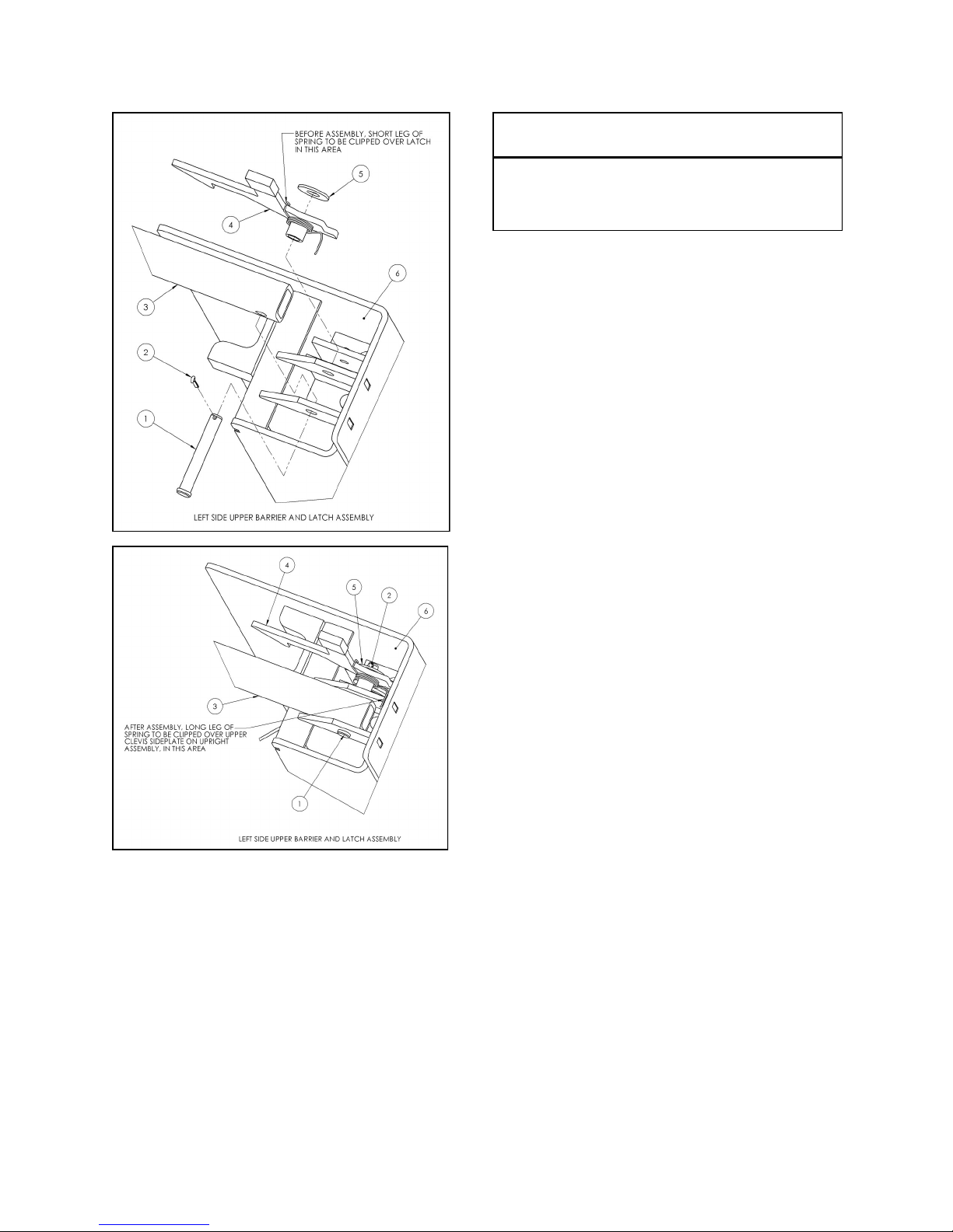
12. Install the left side barrier and latch in the same
manner as the right side. See Figures 6 & 7.
Figure 4
NOVA Dock Sentinel
TM
Installation Manual
5
Page 6
STEP 3: INSTALLING THE UPPER BARRIER
Figure 6
Confirm that the upright is plumb with level
on the front and back and shim as required
prior to securing anchors.
IMPORTANT
Figure 7
1. Confirm the alignment of the barriers and drill
and anchor holes 6-8 as shown in the order
shown in Figure 3 and using the same steps as
before.
6
NOVA Dock Sentinel
TM
Installation Manual
Page 7
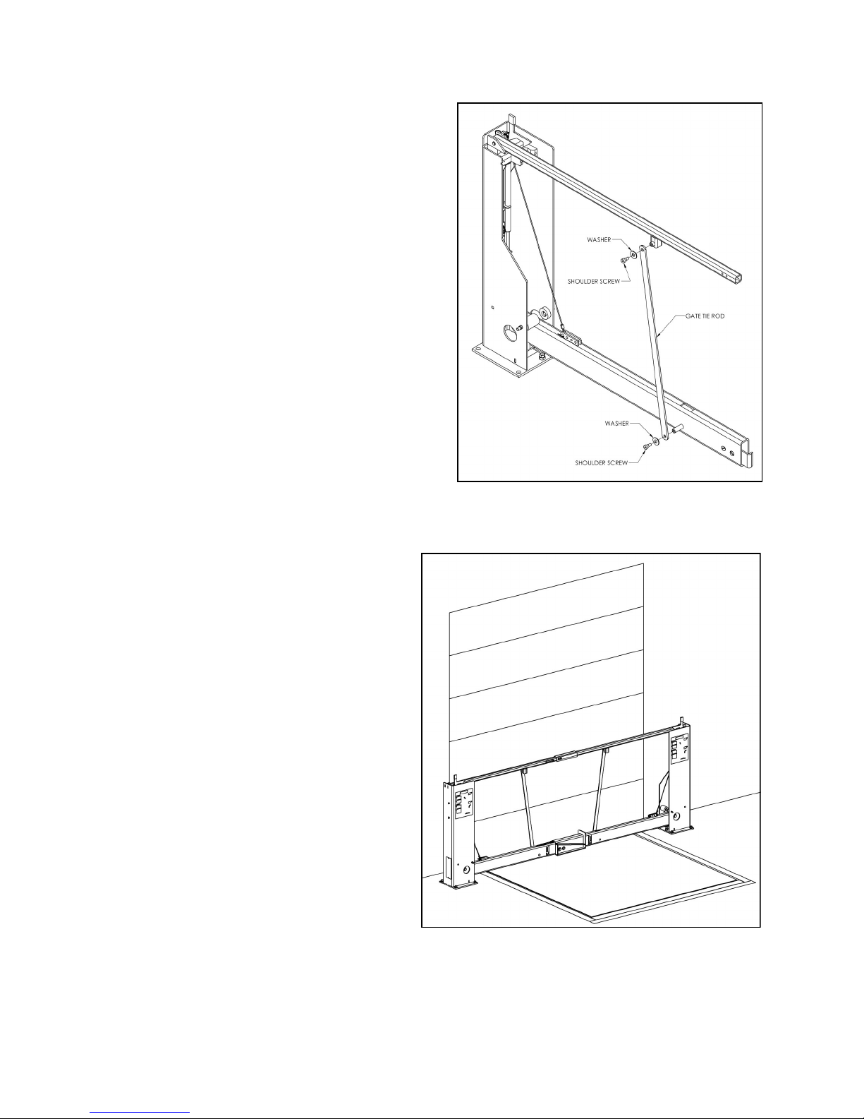
STEP 4: CONNECTING THE TIE RODS
Attach the gate tie rod with the shoulder bolts
and washers as shown. Tighten the shoulder
bolt with a 1/4” allen wrench.
Figure 8
STEP 5: FINAL CHECK
1. Check all connections to be certain they are
secure.
2. Open and close the gate per the Operating
Instructions on page 8 and verify proper
operation.
3. Use paint provided to touch up any nicks or
scratches incurred during installation
process (if needed).
Figure 9
NOVA Dock Sentinel
TM
Installation Manual
7
Page 8
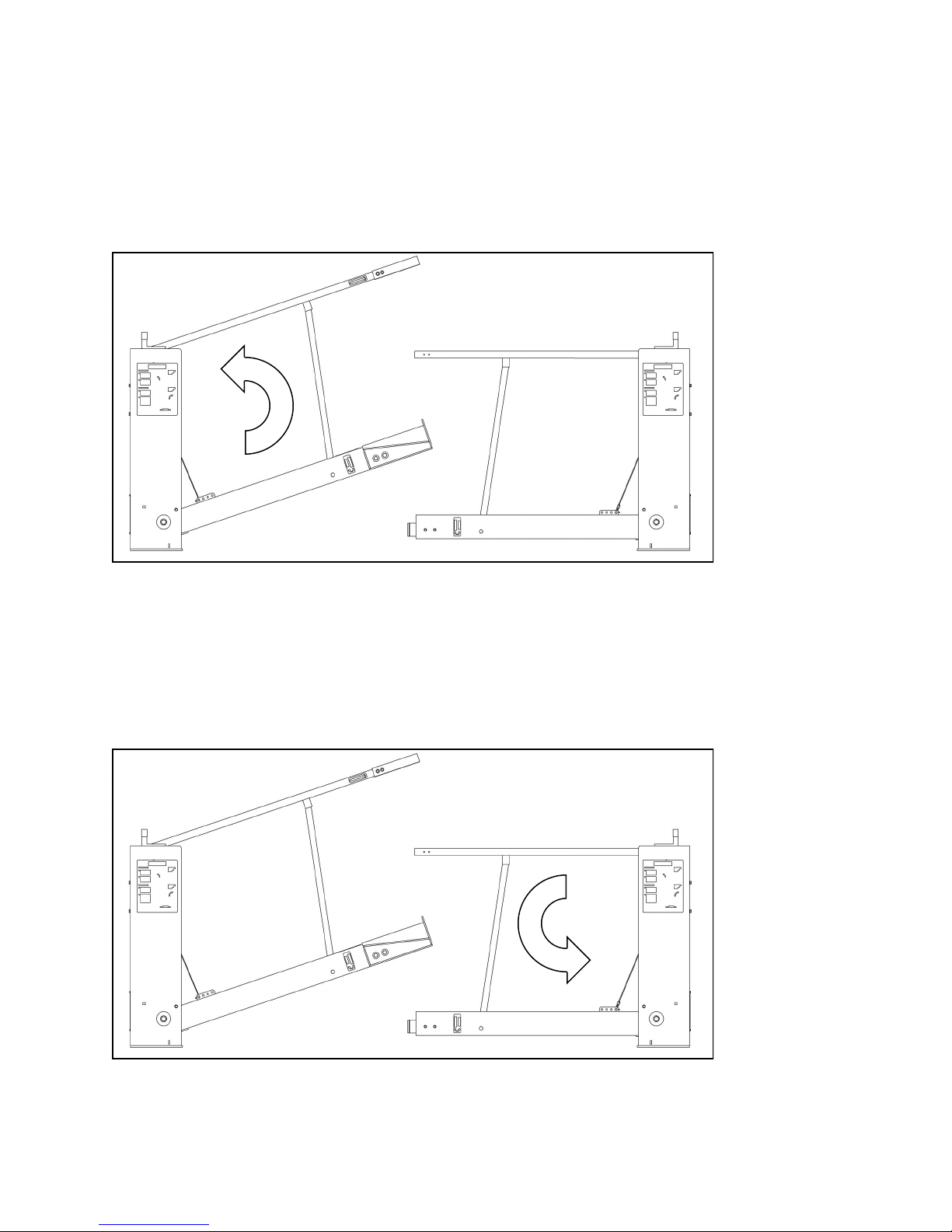
TO OPEN GATE
OPERATING INSTRUCTIONS
1. Lift the left side gate barrier until it is vertical
and the latch engages.
Figure 10—Opening Gate
2. Lift the right side gate barrier until it is vertical
and the latch engages.
LEFT SIDE
FIRST TO
OPEN
TO CLOSE GATE
1. Release the latch on the right side gate barrier
and lower until it is horizontal.
Figure 11—Closing Gate
2. Release the latch on the left side gate barrier
and lower until it is horizontal and engaged
with the right side barrier.
RIGHT SIDE
FIRST TO
CLOSE
8
NOVA Dock Sentinel
TM
Installation Manual
Page 9

GATE ADJUSTMENTS
NOTE: All DOCK SENTINELTM dock gates come
pre-adjusted from the factory and should not
require readjustment after installation. Please
follow these procedures in the event that
adjustments become necessary.
LOWER BARRIER LEVEL ADJUSTMENT
The level on the lower barrier is controlled with
two adjusting screws as shown in Figure 12.
To adjust, loosen nuts and adjust screws up or
down as required. Retighten nuts when
complete.
Figure 12
NOVA Dock Sentinel
TM
Installation Manual
9
Page 10

LIFTING FORCE ADJUSTMENT
Do not adjust the lifting force on the gate so
that the barriers rise without any assistance
from the person operating the gate.
The lifting force required to open the gate can be
adjusted based on the location of the wire rope in
the clevis plate as shown in Figure 13. Moving
the cable towards the center of the gate
decreases the opening force while moving the
cable away from the center increases the
opening force.
1. Loosen the jam nuts that connect the cable
to the gas spring tie bar as shown in Figure
13. Loosen fully, but do not remove the
lower jam nut.
When loosening the jam nuts, do not allow
the wire rope assembly to rotate with the nut.
CAUTION
!
IMPORTANT
The lower barrier will fall when cable is
disconnected if not supported. Take
adequate precautions to prevent the barrier
from falling as it will cause damage or injury
to anything in its path.
2. Raise the lower barrier until cable becomes
slack. Disconnect cable from wire rope
clevis plate and reconnect in appropriate
hole.
3. Tighten lower jam nut until there is no slack
in the cable system throughout the open and
closing of the gate. Tighten upper jam nut to
lock system.
WARNING
!
Figure 13
10 NOVA Dock Sentinel
TM
Installation Manual
Page 11

BARRIER STABILIZER ADJUSTMENT
TM
Installation Manual
Figure 14
11 NOVA Dock Sentinel
Page 12

LEFT SIDE MAIN ASSEMBLY
PARTS LISTS
12
NOVA Dock Sentinel
Figure 15
TM
Installation Manual
Page 13

LEFT SIDE MAIN ASSEMBLY
ITEM NO. PART NUMBER DESCRIPTION QTY.
1 DG-068-000 5/8-11 HEX NYLOCK NUT 1
2 DG-069-000 1/2" FLAT WASHER PLATED 7
3 DG-070-000 5/8" FLAT WASHER PLATED 2
4 DG-071-000 1/4" FLAT WASHER 4
5 DG-072-000 1/4"-20 ELASTIC HEX NUT 2
6 DG-089-000
1/4” - 20 x 1/2” ROUND HEAD PHILLIPS
SCREW
2
7 DG-074-000 1/2"-13 x 3-1/2" HH CAP SCREW 2
8 DG-075-000 3/8"DIA X 1 3/8" CLEVIS PIN 1
9 DG-076-000 COTTER PIN 2
10 DG-077-000 1/2" X 3 1/2" CLEVIS PIN 1
11 DG-001-001A2.2 BUSHING 1
12 DG-006-000 LOWER SADDLE 1
13 DG-008-000 TOP ALIGNMENT 1
14 DG-012-002A1 5/8"-11 X 3-1/2" HH CAP SCREW 1
15 DG-015-007 LOWER BAR RUBBER STOP 1
16 DG-088-000
1/4” - 20 x 1-1/2” ROUND HEAD PHILLIPS
SCREW
2
17 DG-017-000 LEFT SIDE UPPER BARRIER 1
18 DG-019-000 LEFT SIDE LOWER BARRIER 1
19 DG-024-000 GLAD HAND W/SPACER 1
20 DG-029-000 1/4"-20 X 2-1/4"HH CAP SCREW 2
21 DG-039-000 UPRIGHT ACCESS COVER 1
22 DG-044-000 LEFT LATCH ASSEMBLY 1
23 DG-049-001 LEFT SIDE UPRIGHT WELDMENT 1
24 DG-050-000 TIE ROD, GATE 1
25 DG-053-000 3/8"-16 SHOULDER SCREW 2
26 DG-060-000 SHIM, SADDLE 4
27 DG-078-000 1/2"-13 NYLOCK NUT PLATED 2
NOVA Dock Sentinel
TM
Installation Manual
13
Page 14

LEFT SIDE SECONDARY ASSEMBLY
Figure 16
14
NOVA Dock Sentinel
TM
Installation Manual
Page 15

LEFT SIDE SECONDARY ASSEMBLY
ITEM NO. PART NUMBER DESCRIPTION QTY.
1 DG-015-010 1/2"-13 X 2" HH CAP SCREW 1
2 DG-033-000 WIRE ROPE ASSEMBLY 1
3 DG-034-000 SHORT STABILIZER 1
4 DG-035-000 TALL STABILIZER 1
5 DG-038-000
PULLEY/GAS SPRING MOUNTING ASSEMBLY
(100# GAS SPRING)
1
6 DG-049-001 LEFT SIDE UPRIGHT WELDMENT 1
7 DG-064-000 3/8"-16 X 1 1/2" HH CAP SCREW 1
8 DG-065-000 3/8"-16 x 3 1/2" HH CAP SCREW 1
9 DG-079-000 1/2"-13 x 1-1/2"HH CAP SCREW 1
10 DG-080-000 1/2"-13 HEX NUT PLATED 2
11 DG-082-000 3/8" LOCK WASHER PLATED 2
12 DG-083-000 3/8"-16 X 3/4" HH SCREW 2
13 DG-084-000 3/8" JAM NUT 6
NOVA Dock Sentinel
TM
Installation Manual
15
Page 16

POWER PACK ASSEMBLIES (LEFT AND RIGHT)
ITEM
NO.
PART NUMBER DESCRIPTION QTY.
1 DG-075-000 3/8"DIA X 1 3/8" CLEVIS PIN 1
2 DG-076-000 COTTER PIN 1
3 DG-015-003 GAS SPRING TIE BAR 1
4 DG-015-004 M8 X 1.25 NUT 2
5 DG-015-005 PULLEY 1
6 DG-038-001 PULLEY/GAS SPRING MOUNTING WELDMENT 1
7 DG-047-000 GAS SPRING (100#) 2
7 DG-036-000 GAS SPRING (75#) 2
16
Figure 17
NOVA Dock Sentinel
TM
Installation Manual
Page 17

NOTES
This page left intentionally blank.
TM
Installation Manual
17 NOVA Dock Sentinel
Page 18

RIGHT SIDE MAIN ASSEMBLY
Figure 18
18
NOVA Dock Sentinel
TM
Installation Manual
Page 19

RIGHT SIDE MAIN ASSEMBLY
ITEM NO. PART NUMBER DESCRIPTION QTY.
1 DG-068-000 5/8-11 HEX NYLOCK NUT 1
2 DG-069-000 1/2" FLAT WASHER PLATED 3
3 DG-070-000 5/8" FLAT WASHER PLATED 2
4 DG-089-000
1/4” - 20 x 1/2” ROUND HEAD PHILLIPS
SCREW
2
5 DG-075-000 3/8"DIA X 1 3/8" CLEVIS PIN 1
6 DG-076-000 COTTER PIN 2
7 DG-077-000 1/2" X 3 1/2" CLEVIS PIN 1
8 DG-001-001A2.2 BUSHING 1
9 DG-012-002A1 5/8"-11 X 3-1/2" HH CAP SCREW 1
10 DG-015-007 LOWER BAR RUBBER STOP 1
11 DG-088-000
1/4” - 20 x 1-1/2” ROUND HEAD PHILLIPS
SCREW
2
12 DG-018-000 RIGHT SIDE UPPER BARRIER 8’ 1
12 DG-119-000 RIGHT SIDE UPPER BARRIER 8’-6” 1
12 DG-105-000 RIGHT SIDE UPPER BARRIER 9’ 1
13 DG-020-000 RIGHT SIDE LOWER BARRIER 8’ 1
13 DG-106-000 RIGHT SIDE LOWER BARRIER 9’ 1
13 DG-120-000 RIGHT SIDE LOWER BARRIER 8’-6” 1
14 DG-110-000 GLAD HAND W/NUTS 1
15 DG-032-000 1/2"-13 X 1-1/4" FLAT HEAD SCREW 2
16 DG-037-001 RIGHT SIDE UPRIGHT WELDMENT 1
17 DG-039-000 UPRIGHT ACCESS COVER 1
18 DG-045-000 RIGHT LATCH ASSEMBLY 1
19 DG-050-000 TIE ROD, GATE 1
20 DG-053-000 3/8"-16 SHOULDER SCREW 2
NOVA Dock Sentinel
TM
Installation Manual
19
Page 20

RIGHT SIDE SECONDARY ASSEMBLY
Figure 19
20 NOVA Dock Sentinel
TM
Installation Manual
Page 21

RIGHT SIDE SECONDARY ASSEMBLY
ITEM NO. PART NUMBER DESCRIPTION QTY.
1 DG-015-010 1/2"-13 X 2" HH CAP SCREW 1
2 DG-033-000 WIRE ROPE ASSEMBLY 1
3 DG-034-000 SHORT STABILIZER 1
4 DG-035-000 TALL STABILIZER 1
5 DG-037-001 RIGHT SIDE UPRIGHT WELDMENT 1
6 DG-059-000
6 DG-038-000
6 DG-038-000
PULLEY/GAS SPRING MOUNTING ASSEMBLY
8’ (75# GAS SPRING)
PULLEY/GAS SPRING MOUNTING ASSEMBLY
9’ (100# GAS SPRING)
PULLEY/GAS SPRING MOUNTING ASSEMBLY
8’-6” (100# GAS SPRING)
1
1
1
7 DG-064-000 3/8"-16 X 1 1/2" HH CAP SCREW 1
8 DG-065-000 3/8"-16 x 3 1/2" HH CAP SCREW 1
9 DG-079-000 1/2"-13 x 1-1/2"HH CAP SCREW 1
10 DG-080-000 1/2"-13 HEX NUT PLATED 2
11 DG-082-000 3/8" LOCK WASHER PLATED 2
12 DG-083-000 3/8"-16 X 3/4" HH SCREW 2
13 DG-084-000 3/8" JAM NUT 6
NOVA Dock Sentinel
TM
Installation Manual
21
Page 22

LATCH ASSEMBLIES
Figure 20
ITEM NO. PART NUMBER DESCRIPTION QTY.
1 DG-040-000 LEFT LATCH 1
2 DG-051-000 LEFT LATCH SPRING 1
3 DG-046-000 LEFT LATCH HANDLE 1
Figure 21
ITEM NO. PART NUMBER DESCRIPTION QTY.
1 DG-041-000 RIGHT LATCH 1
2 DG-046-000 RIGHT LATCH HANDLE 1
3 DG-052-000 RIGHT LATCH SPRING 1
22
NOVA Dock Sentinel
TM
Installation Manual
Page 23

ANCHORS AND DECALS
Figure 22
ITEM NO. PART NUMBER DESCRIPTION QTY.
1 DG-067-000 ANCHOR BOLT 8
2 DG-054-000 "CLOSE FIRST" DECAL 1
3 DG-055-000 "CLOSE LAST" DECAL 1
4 DG-056-000 "OPEN FIRST" DECAL 1
5 DG-057-000 "CONFIRM CLOSE" DECAL 1
6 DG-058-000 OPERATING INSTRUCTIONS DECAL 2
7 DG-100-000 WARNING DECAL 2
8 DG-101-000 SHIM, FLAT 12
TOUCH-UP PAINT
PART NUMBER DESCRIPTION
DG-099-000 TOUCH-UP PAINT, 4 oz. SPRAY
DG-103-000 TOUCH-UP PAINT, 1/2 oz. BRUSH
NOVA Dock Sentinel
TM
Installation Manual
23
Page 24

WARRANTY
NOVA TECHNOLOGY INTERNATIONAL, LLC. warrants the DOCK SENTINEL™ SAFETY GATE to
be free of defects in material or workmanship under normal use for a period of one year from the date
of shipment. This warranty does not cover any failure to properly maintain the product. This warranty
is the only one given by NOVA TECHNOLOGY INTERNATIONAL, LLC. and is in lieu of all guarantees and
warranties expressed or implied by anyone other than NOVA TECHNOLOGY INTERNATIONAL, LLC,
including those of fitness for a particular purpose and merchantability. In order for warranty claims to be
honored the products must have been properly installed, maintained, and operated within their intended
function and not otherwise abused.
If your DOCK SENTINEL™ SAFETY GATE is defective in material or workmanship and you notify NOVA
TECHNOLOGY INTERNATIONAL, LLC within one year of the date of shipment, NOVA TECHNOLOGY
INTERNATIONAL, LLC will, at its option, repair or replace the defective component(s) at no cost to you.
NOVA TECHNOLOGY INTERNATIONAL, LLC. will not be responsible for or pay for loss of time,
inconvenience, loss of the use of the product, or property damage caused by this product or its failure to
work, or any other incidental or consequential damages.
N90W14507 Commerce Drive Menomonee Falls, WI 53051
Phone 262-502-1591 | 800-236-7325 | fax 262-502-1511
24
www.novalocks.com
NOVA Dock Sentinel
TM
Installation Manual
 Loading...