

Page 1
SPRITE WAREWASH
DISPENSING SYSTEM
Copyright 1999 Nova Controls, Inc.
Reference Manual
DM-400 Series
P/N 20-06270-00 Rev . N
P/N 20-06270-00 Rev. N
Page 2

Page 3

Table of Contents
1 Description of Features
Overview . . . . . . . . . . . . . . . . . . . . . . . . . . . . . . . . . . . . . . . . . . . . . . . . . . . . . . . . . . . . . 1-1
2 Mechanical Installation
Overview . . . . . . . . . . . . . . . . . . . . . . . . . . . . . . . . . . . . . . . . . . . . . . . . . . . . . . . . . . . . . 2-1
Wall Mounting . . . . . . . . . . . . . . . . . . . . . . . . . . . . . . . . . . . . . . . . . . . . . . . . . . . . . . . . . 2-2
Probe Mounting . . . . . . . . . . . . . . . . . . . . . . . . . . . . . . . . . . . . . . . . . . . . . . . . . . . . . . . 2-2
Rinse Injection Fitting . . . . . . . . . . . . . . . . . . . . . . . . . . . . . . . . . . . . . . . . . . . . . . . . . . 2-3
Detergent Bulkhead Fitting . . . . . . . . . . . . . . . . . . . . . . . . . . . . . . . . . . . . . . . . . . . . . . 2-3
Rinse and Detergent Supply and Discharge Tubes . . . . . . . . . . . . . . . . . . . . . . . . . . 2-4
Solenoid Water Feed . . . . . . . . . . . . . . . . . . . . . . . . . . . . . . . . . . . . . . . . . . . . . . . . . . . 2-4
3 Electrical Installation
Overview . . . . . . . . . . . . . . . . . . . . . . . . . . . . . . . . . . . . . . . . . . . . . . . . . . . . . . . . . . . . . 3-1
Probe Wiring . . . . . . . . . . . . . . . . . . . . . . . . . . . . . . . . . . . . . . . . . . . . . . . . . . . . . . . . . . 3-2
Electrical Connections . . . . . . . . . . . . . . . . . . . . . . . . . . . . . . . . . . . . . . . . . . . . . . . . . . 3-2
Main Power Wiring . . . . . . . . . . . . . . . . . . . . . . . . . . . . . . . . . . . . . . . . . . . . . . . . . . . . . 3-3
115 VAC . . . . . . . . . . . . . . . . . . . . . . . . . . . . . . . . . . . . . . . . . . . . . . . . . . . . . 3-3
208/240 VAC . . . . . . . . . . . . . . . . . . . . . . . . . . . . . . . . . . . . . . . . . . . . . . . . . . 3-3
230 VAC . . . . . . . . . . . . . . . . . . . . . . . . . . . . . . . . . . . . . . . . . . . . . . . . . . . . . 3-3
Detergent Signal Wiring . . . . . . . . . . . . . . . . . . . . . . . . . . . . . . . . . . . . . . . . . . . . . . . . . 3-3
Detergent Signal Wiring – Probe Mode . . . . . . . . . . . . . . . . . . . . . . . . . . . . . . . . 3-3
Detergent Signal Wiring – Probeless Mode . . . . . . . . . . . . . . . . . . . . . . . . . . . . 3-4
Rinse Signal Wiring . . . . . . . . . . . . . . . . . . . . . . . . . . . . . . . . . . . . . . . . . . . . . . . . . . . . 3-4
4 Description of Controls
Overview . . . . . . . . . . . . . . . . . . . . . . . . . . . . . . . . . . . . . . . . . . . . . . . . . . . . . . . . . . . . . 4-1
Key Description . . . . . . . . . . . . . . . . . . . . . . . . . . . . . . . . . . . . . . . . . . . . . . . . . . . . . . . 4-1
5 User Mode Operation
Overview . . . . . . . . . . . . . . . . . . . . . . . . . . . . . . . . . . . . . . . . . . . . . . . . . . . . . . . . . . . . . 5-1
Display Indicators . . . . . . . . . . . . . . . . . . . . . . . . . . . . . . . . . . . . . . . . . . . . . . . . . . . . . . 5-1
User Mode Menus . . . . . . . . . . . . . . . . . . . . . . . . . . . . . . . . . . . . . . . . . . . . . . . . . . . . . . 5-2
Guide to Icons . . . . . . . . . . . . . . . . . . . . . . . . . . . . . . . . . . . . . . . . . . . . . . . . . . . . 5-2
Visual Alarm Displays . . . . . . . . . . . . . . . . . . . . . . . . . . . . . . . . . . . . . . . . . . . . . . 5-2
Rack Counter (Menu 11) . . . . . . . . . . . . . . . . . . . . . . . . . . . . . . . . . . . . . . . . . . . . 5-2
Detergent Prime (Menu 12) . . . . . . . . . . . . . . . . . . . . . . . . . . . . . . . . . . . . . . . . . . 5-3
Rinse Prime (Menu 13) . . . . . . . . . . . . . . . . . . . . . . . . . . . . . . . . . . . . . . . . . . . . . 5-3
De-Lime (Menu 14). . . . . . . . . . . . . . . . . . . . . . . . . . . . . . . . . . . . . . . . . . . . . . . . . 5-3
Live Conductivity Display. . . . . . . . . . . . . . . . . . . . . . . . . . . . . . . . . . . . . . . . . . . 5-3
Alarms (Probe Mode Only) . . . . . . . . . . . . . . . . . . . . . . . . . . . . . . . . . . . . . . . . . . . . . . 5-4
Low Detergent Alarm. . . . . . . . . . . . . . . . . . . . . . . . . . . . . . . . . . . . . . . . . . . . . . . 5-4
Detergent Overfeed Stop Alarm. . . . . . . . . . . . . . . . . . . . . . . . . . . . . . . . . . . . . . 5-4
Manual Initial Charge . . . . . . . . . . . . . . . . . . . . . . . . . . . . . . . . . . . . . . . . . . . . . . . . . . . 5-4
Password Access to Program Mode . . . . . . . . . . . . . . . . . . . . . . . . . . . . . . . . . . . . . . 5-4
P/N 20-06270-00 Rev. N iii
Page 4

6 Program Mode Operation
Overview . . . . . . . . . . . . . . . . . . . . . . . . . . . . . . . . . . . . . . . . . . . . . . . . . . . . . . . . . . . . . 6-1
Program Mode Access . . . . . . . . . . . . . . . . . . . . . . . . . . . . . . . . . . . . . . . . . . . . . . . . . . 6-1
Configuration Settings . . . . . . . . . . . . . . . . . . . . . . . . . . . . . . . . . . . . . . . . . . . . . . . . . . 6-3
Detergent Control (Menu 21) . . . . . . . . . . . . . . . . . . . . . . . . . . . . . . . . . . . . . . . . 6-3
Machine Type (Menu 22). . . . . . . . . . . . . . . . . . . . . . . . . . . . . . . . . . . . . . . . . . . . 6-3
Detergent Type (Menu 23.1) . . . . . . . . . . . . . . . . . . . . . . . . . . . . . . . . . . . . . . . . . 6-4
Pulse Feed – Capsule Detergent Only (Menu 23.2) . . . . . . . . . . . . . . . . . . . . . . 6-4
Alarm Volume (Menu 24). . . . . . . . . . . . . . . . . . . . . . . . . . . . . . . . . . . . . . . . . . . . 6-4
Rack Time in Rinse (Menu 25) . . . . . . . . . . . . . . . . . . . . . . . . . . . . . . . . . . . . . . . 6-4
Initial Charge - Probeless Only (Menu 26). . . . . . . . . . . . . . . . . . . . . . . . . . . . . . 6-5
Manual Initial Charge. . . . . . . . . . . . . . . . . . . . . . . . . . . . . . . . . . . . . . . . . . . 6-5
Automatic Initial Charge . . . . . . . . . . . . . . . . . . . . . . . . . . . . . . . . . . . . . . . . 6-5
Change Installer Password (Menu 27). . . . . . . . . . . . . . . . . . . . . . . . . . . . . . . . . 6-5
Demo Mode (Menu 28). . . . . . . . . . . . . . . . . . . . . . . . . . . . . . . . . . . . . . . . . . . . . . 6-5
Adjustments—Probe Mode (Menu 3) . . . . . . . . . . . . . . . . . . . . . . . . . . . . . . . . . . . . . . 6-6
Detergent Tank Reading (Menu 31) . . . . . . . . . . . . . . . . . . . . . . . . . . . . . . . . . . . 6-6
Detergent Set Point (Menu 32.1). . . . . . . . . . . . . . . . . . . . . . . . . . . . . . . . . . . . . . 6-6
Live Conductivity Display (Menu 32.2) . . . . . . . . . . . . . . . . . . . . . . . . . . . . . . . . 6-7
Rinse Pump Speed (Menu 33) . . . . . . . . . . . . . . . . . . . . . . . . . . . . . . . . . . . . . . . 6-7
Low Detergent Alarm Delay (Menu 34) . . . . . . . . . . . . . . . . . . . . . . . . . . . . . . . . 6-7
Rinse Feed Option (Menu 35) . . . . . . . . . . . . . . . . . . . . . . . . . . . . . . . . . . . . . . . . 6-7
Rinse Delay Time (Menu 36) . . . . . . . . . . . . . . . . . . . . . . . . . . . . . . . . . . . . . . . . . 6-8
Adjustments—Probeless Mode (Menu 4) . . . . . . . . . . . . . . . . . . . . . . . . . . . . . . . . . . . 6-8
Detergent Initial Charge (Menu 41) . . . . . . . . . . . . . . . . . . . . . . . . . . . . . . . . . . . 6-9
Detergent Dose (Menu 42) . . . . . . . . . . . . . . . . . . . . . . . . . . . . . . . . . . . . . . . . . . 6-9
Detergent Dose Interval (Menu 43). . . . . . . . . . . . . . . . . . . . . . . . . . . . . . . . . . . . 6-9
Rinse Pump Speed (Menu 44) . . . . . . . . . . . . . . . . . . . . . . . . . . . . . . . . . . . . . . 6-10
Rinse Feed Option (Menu 45) . . . . . . . . . . . . . . . . . . . . . . . . . . . . . . . . . . . . . . . 6-10
Rinse Delay Time (Menu 46) . . . . . . . . . . . . . . . . . . . . . . . . . . . . . . . . . . . . . . . . 6-10
7 Troubleshooting
Overview . . . . . . . . . . . . . . . . . . . . . . . . . . . . . . . . . . . . . . . . . . . . . . . . . . . . . . . . . . . . . 7-1
Alarms and Indicators . . . . . . . . . . . . . . . . . . . . . . . . . . . . . . . . . . . . . . . . . . . . . . . . . . 7-1
Preliminary Checks . . . . . . . . . . . . . . . . . . . . . . . . . . . . . . . . . . . . . . . . . . . . . . . . . . . . 7-1
Dead Unit (No Display) . . . . . . . . . . . . . . . . . . . . . . . . . . . . . . . . . . . . . . . . . . . . . . . . . . 7-1
No Detergent Feed . . . . . . . . . . . . . . . . . . . . . . . . . . . . . . . . . . . . . . . . . . . . . . . . . . . . . 7-2
Excess Detergent Consumption . . . . . . . . . . . . . . . . . . . . . . . . . . . . . . . . . . . . . . . . . . 7-2
No Rinse Feed . . . . . . . . . . . . . . . . . . . . . . . . . . . . . . . . . . . . . . . . . . . . . . . . . . . . . . . . 7-2
8 Maintenance and Service
Overview . . . . . . . . . . . . . . . . . . . . . . . . . . . . . . . . . . . . . . . . . . . . . . . . . . . . . . . . . . . . . 8-1
Maintenance . . . . . . . . . . . . . . . . . . . . . . . . . . . . . . . . . . . . . . . . . . . . . . . . . . . . . . . . . . 8-1
Pump Tube Replacement . . . . . . . . . . . . . . . . . . . . . . . . . . . . . . . . . . . . . . . . . . . . . . . 8-1
Service Disassembly . . . . . . . . . . . . . . . . . . . . . . . . . . . . . . . . . . . . . . . . . . . . . . . . . . . 8-2
Spare Parts . . . . . . . . . . . . . . . . . . . . . . . . . . . . . . . . . . . . . . . . . . . . . . . . . . . . . . . . . . . 8-3
9 Specifications
Limited Warranty . . . . . . . . . . . . . . . . . . . . . . . . . . . . . . . . . . . . . . . . . . . . . . . . . . . . . . 9-2
Limitation of Liability. . . . . . . . . . . . . . . . . . . . . . . . . . . . . . . . . . . . . . . . . . . . . . . 9-2
Index
iv P/N 20-06270-00 Rev. N
Page 5

Description of Features
Overview
This chapter describes the features of the Sprite Warewash Dispensing System.
Advanced Design
The SPRITE uses miniaturized electronics to provide powerful features in a small package. A digital
readout allows simple, three-button programming of all options.
Reliability
The gasket-enclosed SPRITE Warewash Dispenser is highly water resistant and the electronics are
further protected within the enclosure. The readout gives confirmation of detergent and rinse feeds.
Versatility
The SPRITE can be configured as a conductivity probe controlled unit or as a probeless, time-based
dispenser. It can accept a 100-115VAC nominal to 200-249VAC nominal (+/- 10% fluctuation) main
power input at 50 or 60 Hz. Rinse and Detergent control signals are universal “machine interface”
types that are capable of accepting any voltage from 24 to 240 VAC nominal (+/- 10% fluctuation) or
24 VDC (+/- 20% fluctuation). SPRITE can control either capsule or liquid detergents.
1
Cost Savings
A special Rinse Saver Feature prevents rinse additive waste during fills of the washer. Digital electronics ensure accurate detergent control and minimize overuse.
Intelligence
The SPRITE includes a rack counter as a “standard” feature. A unique “De-Lime” mode allows for
safe washer cleaning without detergent waste.
Choice of Options
A full range of programmable options are included, such as rinse delay, variable alarm volume, and
manual prime for both rinse and detergent.
Easy Service/Repair
The SPRITE features convenient front access for all servicing. No internal access to the cabinet is
required for installation and routine maintenance. In the unlikely event that repairs are required, spare
parts are available in modular form for fast and convenient service.
P/N 20-06270-00 Rev. N 1-1
Page 6

1-2 P/N 20-06270-00 Rev. N
Page 7
Mechanical Installation
Overview
This chapter describes the hardware installation of the Sprite. In this chapter, you will:
• Wall-mount the Sprite
• Mount and Install Probe (if applicable)
• Mount and Install Rinse Injection Fitting
• Mount and Install Detergent Bulkhead Fitting
• Install Rinse and Detergent Supply and Discharge Tubes
• Install Solenoid (if applicable)
2
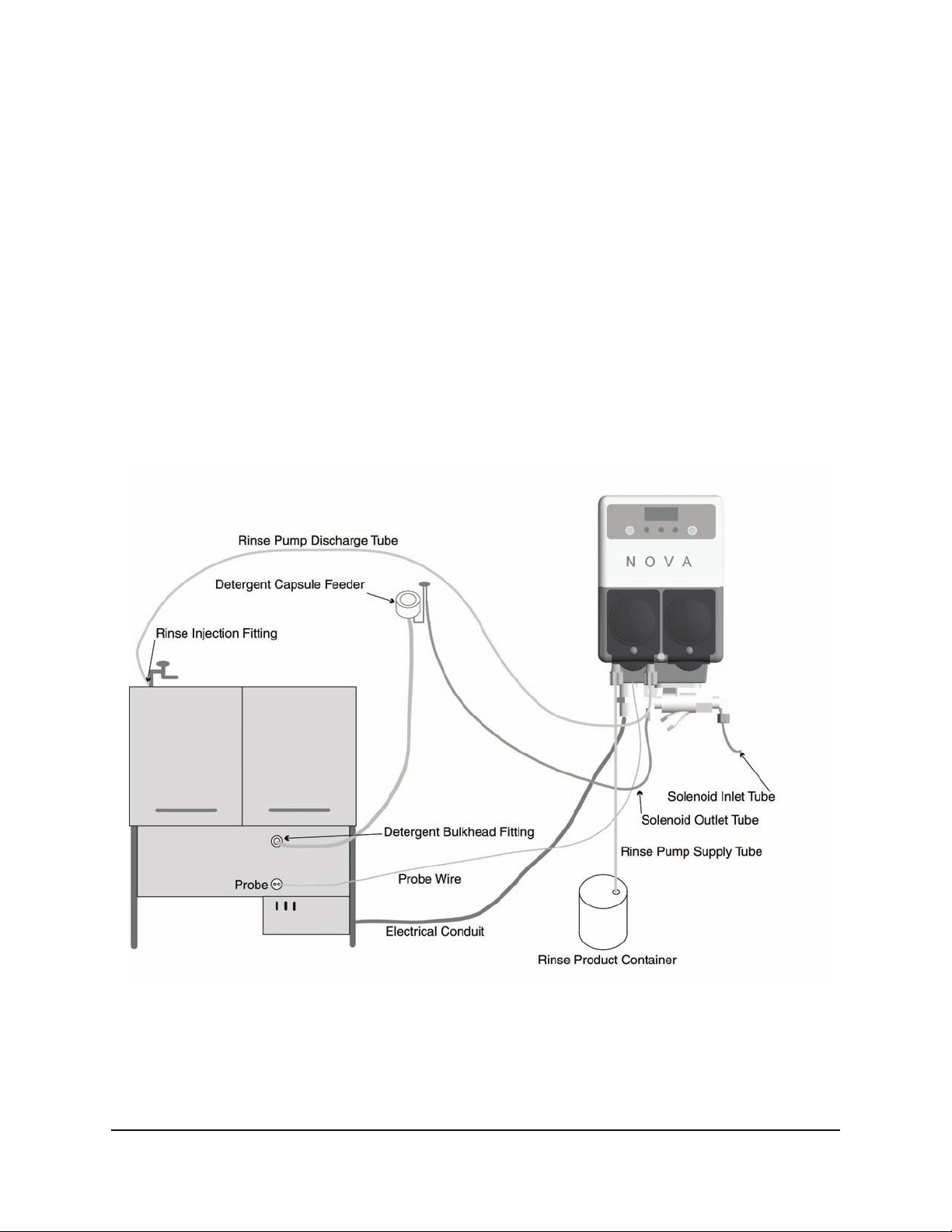
Figure 2-1 System Diagram
P/N 20-06270-00 Rev. N 2-1
Page 8
Wall Mounting
Warning
,
Choose an installation location that is:
The Sprite dispensing system is intended to be installed by experienced installers, in
accordance with all applicable electrical and plumbing codes.
All dish machine and dispenser power must be disconnected during installation and/or
any time the dispenser cabinet is opened.
Mounting Bracket
• Close to the product containers.
• At a reasonable height for easy maintenance access.
• Away from any direct sources of steam, water spray, and high tem-
peratures.
• Close enough to the dish machine electrical control panel to allow
Back of Unit
dispenser wiring without use of an external junction box (not provided) wherever possible.
1. Using mounting bracket as a template, mark holes to drill into mounting
surface. For sheet metal mounting with screws and nuts, drill 1/4" (6
Hang unit from this lip
on to Mounting Bracket
mm) holes. For wall anchors, drill holes as appropriate for anchors used.
2. Attach mounting bracket to mounting surface with hardware provided.
Figure 2-2 Mounting
3. Hang unit on bracket. Optional: Drill hole and attach lower mounting hole to mounting surface.
Probe Mounting
(Probe Operation Only)
Bracket
The probe senses the detergent concentration. Correct probe placement is
critical for accurate detergent concentration control. Always use the new
probe provided with the dispenser.
When choosing a mounting location, make sure that the probe will be completely immersed in the wash tank solution, in an area that has a good flow
of solution, and close to the product entry point.
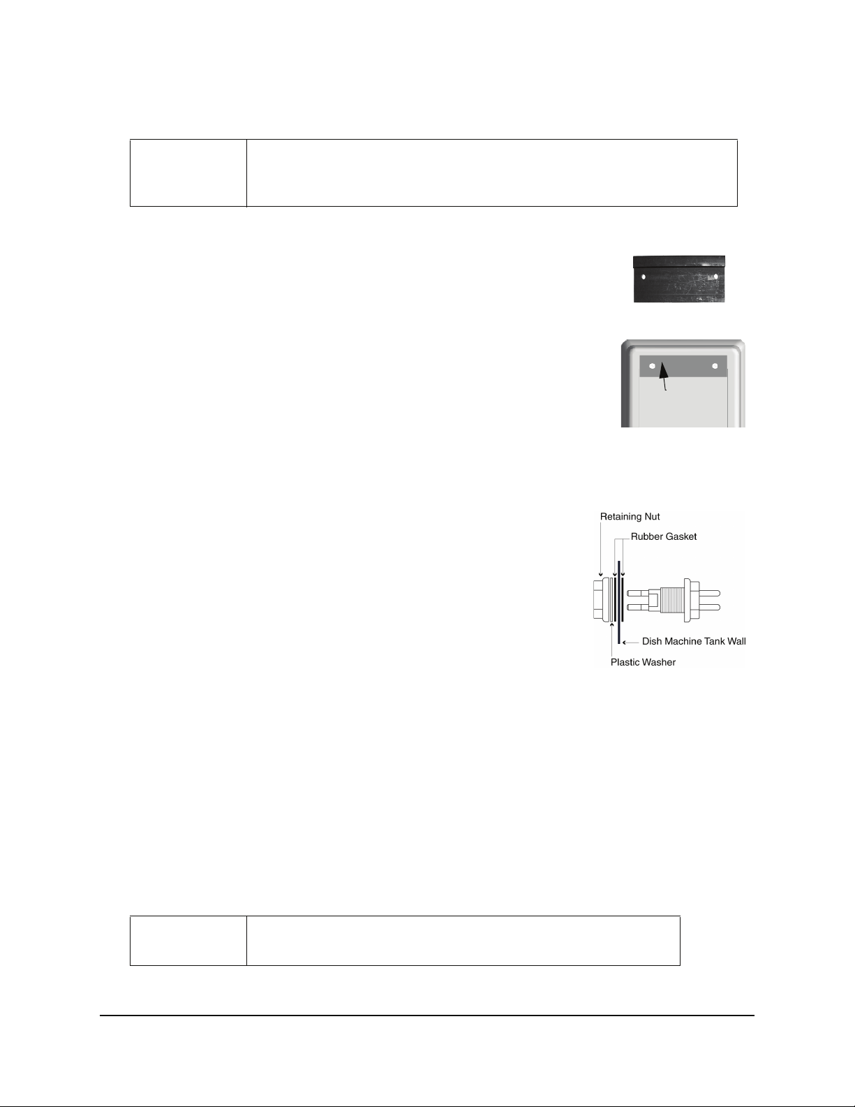
Figure 2-3 Probe Mounting
Many dish machines will have knockouts provided for probe installation and/or will have existing probes.
Previously punched probe holes may be suitable, but always confirm that the probe will be immersed in the
wash tank solution before installing. The following steps describe probe installation.
If a probe hole is present, skip to Step 2.
1. Drill a 3/8" hole in the center of the probe location. Use a Greenlee (or similar) 7/8" hole punch to
cut the final hole.
2. Remove the probe retaining nut.
3. From inside the dish machine tank wall, insert probe (with rubber gasket) into hole.
4. From outside the dish machine tank wall, install second rubber gasket, plastic washer and probe
retaining nut. Tighten finger-tight only.
Warning
,
Do not over-tighten the retaining nut!
2-2 P/N 20-06270-00 Rev. N
Page 9
Rinse Injection Fitting
Install the rinse injection fitting at least 6" below the dish machine
rinse plumbing vacuum breaker to conform to plumbing codes.
The injection fitting threads into 1/8" NPT female threads. If the
dish machine rinse plumbing is thin-wall pipe, use a saddle clamp
Threads into
rinse plumbing
Compression Fitting
(tube from pump)
with a 1/8" NPT threaded hole. If an optional pressure switch will
be used, thread the injection fitting into one side of the pressure
switch water source fitting pipe tee. If the machine already has a
tapped hole to accommodate the fitting, skip to Step 3.
Figure 2-4 Rinse Injection Fitting
Choose a location for the rinse injection fitting that is at least 6" downstream from the solenoid valve and
vacuum breaker. On continuous rack, flight, or conveyor machines, be sure this location is downstream
from any rinse makeup water.
1. Drill a 7/32" hole in the rinse plumbing injection location.
2. Tap the hole drilled in Step 1 with a 1/8" NPT tap.
3. Install the injection fitting. Use thread sealant to ensure a leak-free assembly.
Detergent Bulkhead Fitting
(Liquid Detergent Only)
Caution
,
Follow the instructions provided with your solid, powder, or slurry feed
system for solenoid equipped units instead of using the following section.
Correct placement of the detergent bulkhead fitting is critical for accurate detergent concentration control
(in probe mode only). When choosing a mounting locating, make sure that the detergent bulkhead fitting is:
• Above the water line in the tank.
• Close to the probe location (when possible).
• Discharging detergent directly into the wash tank and not on top of any shelf areas or other
obstacles that could prevent detergent from falling directly into the wash tank.
Previously punched holes may be suitable, but always confirm that the fitting is correctly placed.
If a hole is present, skip to Step 2.
1. Drill a 3/8" hole in the center of the detergent inlet
location. Use a Greenlee (or similar) 7/8" hole
punch to cut the final hole.
2. Remove the detergent bulkhead fitting retaining nut.
3. From inside the machine, insert detergent bulkhead
fitting (with rubber gasket) into hole.
4. From outside the machine, install second rubber gasket, plastic washer and plastic retaining nut. Tighten
finger-tight only.
Figure 2-5 Detergent Bulkhead Fitting
CAUTION: Do not over-tighten the retaining nut.
P/N 20-06270-00 Rev. N 2-3
Page 10
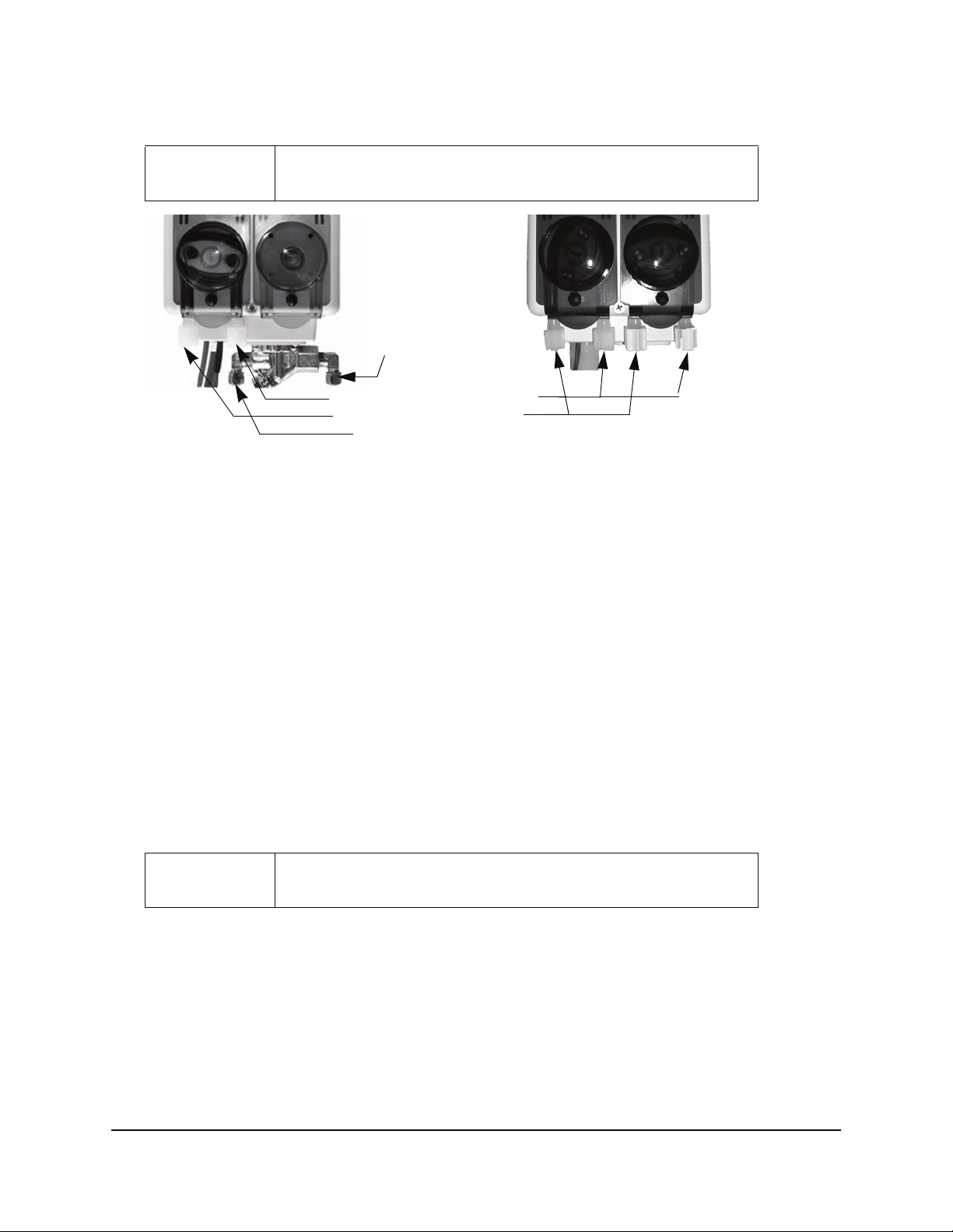
Rinse and Detergent Supply and Discharge Tubes
Note
,
prite DM 411
Figure 2-6 Dispensing System
1. Route pump supply tubes from supply containers to the inlet sides (left) of each respective pump.
Slip the tube through the compression nut into fitting and tighten.
2. Route pump discharge tubes to the outlet sides (right) of each respective pump. Slip the tube
through compression nut into fitting and tighten.
3. Route other end of rinse pump discharge tube to rinse injection fitting installed in “Rinse Injection
Fitting” on page 2-3. Slip the tube through compression nut into fitting and tighten.
4. Route other end of detergent pump discharge tube to the detergent bulkhead fitting (installed in
“Detergent Bulkhead Fitting” on page 2-3
Supply and discharge tubes are not included with the standard unit.
from
water source
pump discharge tube connection
pump supply tube connection
to detergent feed bowl
). Slip tube through compression nut into fitting and tighten.
Sprite DM 420
Solenoid Water Feed
(Solenoid Equipped Units Only)
If you are using a solid, powder or slurry feed system, you will need a water source for the dispenser solenoid valve. This water supply may be hot or cold but, for safety reasons, should not come from th e boosted
temperature rinse water line on high temperature dish machines.
The dispenser solenoid valve fittings are 1/4" (6mm) compression. Typically, a saddle clamp is used for the
solenoid valve water sou rce. If the plumbing is steel or brass, d rill a 7/32" hole and tap for 1/8" NPT threads.
Caution
,
1. Install petcock valve to water source plumbing. Connect 1/4" copper or plastic tube to the valve.
2. Route tube to dispenser solenoid valve. Slide tube into water inlet side compression fitting and
tighten.
3. Connect another 1/4" tube to the outlet side of the dispenser solenoid valve and route to the water
inlet connection for the feed system.
4. Confirm that all compression fittings are tight.
5. Be sure to turn on water source valve prior to adjusting dispenser settings.
If the water source is hot, use only copper tubing; DO NOT use poly tubing.
2-4 P/N 20-06270-00 Rev. N
Page 11

Electrical Installation
Overview
This chapter describes the electrical connections of the Sprite. In this chapter, you will connect:
• Probe Wiring
• Electrical Connections
• Main Power Wiring
• Detergent Signal Wiring (Probe and Probeless modes)
• Rinse Signal Wiring
All electrical connections (except the probe) must be in either the dish
machine control circuit panel or an external junction box.
The dispenser is pre-wired with a multi-conductor electrical cable that must
be run through a conduit to the location where hard-wired connections are
Note
"
made on the dish machine.
Use a 1/2" (13 mm) ID water tight conduit meeting all local and national
codes. A conduit fitting is present on the bottom of the dispenser where the
power cable exits.
3
The probe wire is also pre-wired and should be routed to the probe location
and cut to length if a probe is used.
P/N 20-06270-00 Rev. N 3-1
Page 12
Probe Wiring
1. Route the probe wire to the probe location and cut to fit. If you need to extend the probe wire, use
high quality , corrosion resistant (waterproof is best) butt splices with a good quality crimping tool.
2. Strip wire ends and crimp on the ring lugs provided.
3. Connect the ring lugs to the probe with nuts and star washers provided. Be sure that connections
are tight and secure.
Electrical Connections
Table 3-1 90-130 VAC Main Power
Wire Colors Circuit Voltage Function
Gray/Violet 90-130 VAC 50/60 Hz Main AC Power
Black 90-130 VAC 50/60 Hz Main AC Power
Brown No Connection - Insulate! Warning - Live!
Yellow 24-249 VAC, +24 VDC Detergent Signal
Yellow/White 24-249 VAC, -24 VDC Detergent Signal
Violet 24-249 VAC, +24 VDC Rinse Signal
White/Violet 24-249 VAC, -24 VDC Rinse Signal
Table 3-2 200-249 VAC Main Power
Wire Colors Circuit Voltage Function
Gray/Violet 200-249 VAC 50/60 Hz Main AC Power
Brown 200-249 VAC 50/60 Hz Main AC Power
Black No Connection - Insulate! Warning - Live!
Yellow 24-249 VAC, +24 VDC Detergent Signal
Yellow/White 24-249 VAC, -24 VDC Detergent Signal
Violet 24-249 VAC, +24 VDC Rinse Signal
White/Violet 24-249 VAC, -24 VDC Rinse Signal
Table 3-3 230 VAC Main Power
Wire Colors Circuit Voltage Function
Lt. Blue 200-249 VAC 50/60 Hz Main AC Power
Brown 200-249 VAC 50/60 Hz Main AC Power
Yellow 24-249 VAC, +24 VDC Detergent Signal
Yellow/White 24-249 VAC, -24 VDC Detergent Signal
Violet 24-249 VAC, +24 VDC Rinse Signal
White/Violet 24-249 VAC, -24 VDC Rinse Signal
3-2 P/N 20-06270-00 Rev. N
Page 13
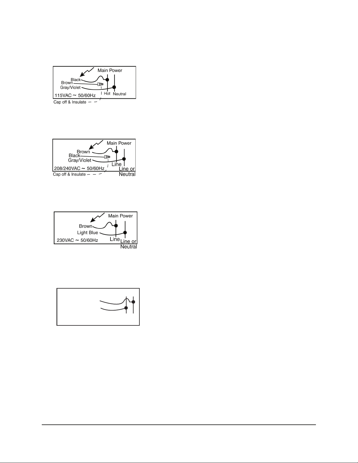
Main Power Wiring
~
115 VAC
Connect the gray with violet stripe wire to the neutral source. Connect the black wire to the 115 line.
Cap off and insulate the brown wire (Wire nut provided).
208/240 VAC
Connect the gray with violet stripe wire to one side of the voltage source. Connect the brown wire to
the other line of the voltage source. Cap off and insulate the black wire (Wire nut provided).
230 VAC
Connect the light blue wire to one side of the voltage source (Neutral, if available). Connect the brown
wire to the other side of the voltage source.
Detergent Signal Wiring
Detergent Signal Wiring
(+) Yellow
(-) White/Yellow
Detergent Signal
Figure 3-1 Detergent Signal Wiring Diagram—Probe or Probeless Mode
The detergent signal input is an optically isolated signal input that draws no more than 20 mA. It is a universal voltage input that accepts any voltage between 24 and 240 VAC nominal (+/- 10% fluctuation), or
24 VDC nominal (+/- 20% fluctuation).
Detergent Signal Wiring – Probe Mode
Typical wiring locations are dispenser detergent power source or the wash motor contacts in the dish
machine control panel. This power source is on when the dishwasher is running the wash pump.
• Connect yellow (DC +) and white/yellow (DC -) colored wires to detergent power source.
24-240V 50/60Hz
or 24V DC
P/N 20-06270-00 Rev. N 3-3
Page 14

Detergent Signal Wiring – Probeless Mode
~
On conveyor type dishwashers, the detergent signal must occur only once per dish machine fill/
drain occurrence–beginning when the dish machine fills. Typical wiring locations are an “on light” or
an electrical tank heat circuit between the tank heater switch and the thermostat. Each time this power
source comes on, and stays on for 10 seconds, the dispenser will feed the detergent initial charge
amount (with probeless and automatic initial charge modes set).
On door-type dishwashers, connect this signal input to the dispenser detergent power source or the
wash motor contacts in the dish machine control panel. This power source is on when the dishwasher
is running the wash pump.
• Connect yellow (DC +) and white/yellow (DC -) colored wires to initial charge power source.
Rinse Signal Wiring
Rinse Signal Wiring
(+) Violet
(-) White/Violet
Rinse Signal
Figure 3-2 Rinse Signal Wiring Diagram
24-240V 50/60Hz
or 24V DC
The rinse signal input is an optically isolated signal input that draws no more than 20 mA. It is a
universal voltage input that accepts any voltage between 24 and 240 VAC nominal (+/- 10%
fluctuation), or 24 VDC nominal (+/- 20% fluctuation). Typical wiring locations are dispenser rinse
power source or the rinse solenoid valve circuit in the dish machine control panel. This power source
is live whenever the dishwasher is rinsing. When no suitable rinse signal connection is available, an
optional pressure switch may be used with a constant power source instead.
• Connect violet (DC +) and white/violet (DC -) colored wires to rinse power source (or constant
power for pressure switch installations).
Probeless Mode
Note
#
Certain dishwasher designs require that the rinse aid be dispensed upon the
detergent signal, rather than the rinse signal. In this case, you must still connect the
rinse signal input to either the fill solenoid or the rinse solenoid circuit of the
dishwasher to enable the automatic initial charge function in probeless mode.
3-4 P/N 20-06270-00 Rev. N
Page 15
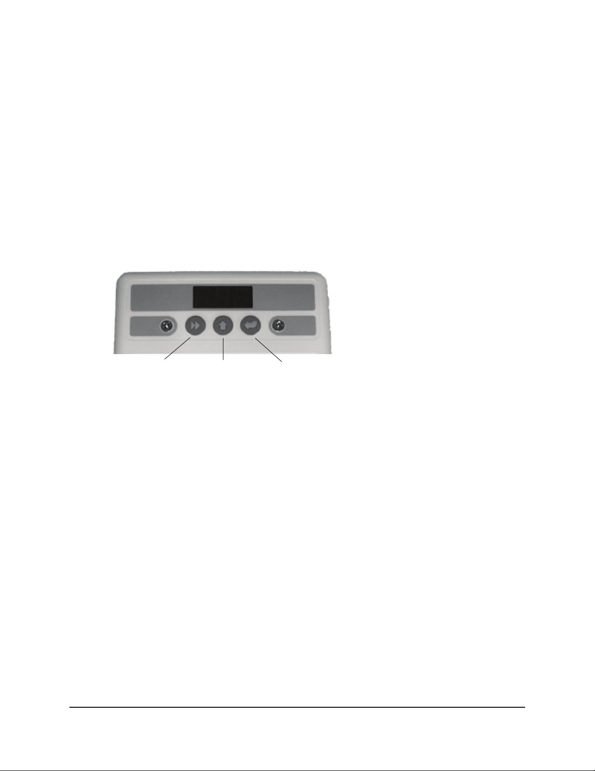
Description of Controls
Overview
The Sprite makes use of only three buttons and a 3-digit LED display for all dispenser operation and programming.
Key Description
Use the menu screen illustrations as a guide when learning to program the Sprite. Use the Next key to
move to all available main menu screens in Program mode.
4
Next Key
Scroll Key Enter Key
Next Key
Use the Next key to move to the next menu or task. The tasks under the Next key are:
• User Mode - Moves through User Mode menu screens.
• Program Mode - Moves through the Program Mode menu screens.
• Input Screens - Moves blinking digit to the right.
Scroll Key
Use the Scroll key to change the blinking digit’s value. The tasks under the Scroll key are:
• User Mode - Changes the values of blinking digits. Activates Probeless Manual Initial Detergent
Charge. See “Manual Initial Charge” on page 5-4.
• Program Mode - Changes value of blinking digits. Selects menu group.
• Input Screens - Changes value of blinking digits.
Enter Key
Use the Enter key to perform a task or set a value. The tasks under the Enter key are:
• User Mode - Starts and stops rinse pump and detergent prime. Accesses Password input screen
(press and hold for two seconds). Performs actions as prompted in User Mode menu screens.
• Program Mode - Accesses all input screens from main menu loop (via Next key).
• Input Screens - Sets displayed value in all input screens (via Scroll key). Exits back to main menu.
P/N 20-06270-00 Rev. N 4-1
Page 16

Guide To Icons
Next key—moves
Scroll key—changes
Enter key—action
Gray (left) digit indicates blinking
Figure 4-1 Guide to Icons
4-2 P/N 20-06270-00 Rev. N
Page 17

User Mode Operation
Overview
This chapter describes the features of User Mode operation. In this chapter, you will learn about:
• Display Indicators
• User Mode menus
• Rack Counter
• Detergent Prime
• Rinse Prime
• De-Lime
• Live Conductivity Display
• Password Access to Program Mode
• Alarms (Probe Mode)
• Low Detergent Alarm (Probe Mode)
• Detergent Overfeed Stop Alarm (Probe Mode)
• Manual Initial Charge (Probeless Mode)
5
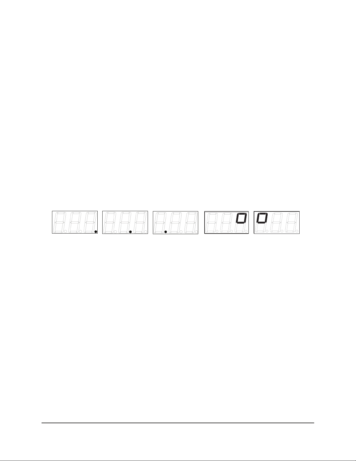
Display Indicators
In User Mode, the dispenser’s operating status is indicated in the following displays (combinations of these
displays occur during normal operation):
• Idle Home Screen (Center Digit): Dash in center digit indicates that power is on.
• Detergent Feed On (Right Digit): One segment continuously rotates clockwise.
• Rinse Pump On (Left Digit): One segment continuously rotates clockwise.
• Alarms (To see these alarms, go to “Visual Alarm Displays” on page 5-2):
• Low Detergent Visual Alarm (Probe Mode Only): Bottom segments flash on all three digits.
• Detergent Overfeed Stop Alarm: Bottom segments flash and the right digit displays a zero.
P/N 20-06270-00 Rev. N 5-1
Page 18

User Mode Menus
Press NEXT to access and move through the User Mode menu loop. The circular menu loop allows you to
return to all screens. All menu screens are numeric; no text appears in any menu screens.
After 30 seconds of inactivity, User Mode automatically returns to either the home screen or, if Live Conductivity is enabled, User Mode returns to the Live Conductivity display.
Idle Home Screen
Rack Counter
Detergent Prime
Rinse Prime
Rinse Pump On
30 seconds, no activity
Tens of Racks
Max Det Time (Probe Only)
Detergent Feeding
Rinse Pump On
RAM Check
Detergent Feed
= Reset Checksum
= Reset Time
Visual Alarm Displays
Guide to Icons
Activates Manual Initial Charge
De-Lime
Live Conductivity Display (if enabled)
De-Lime Cycle On
(Probeless mode)
Figure 5-1 User Mode Menus and Displays
Rack Counter (Menu 11)
1. Press NEXT to display 11.
2. Press
3. Press
5-2 P/N 20-06270-00 Rev. N
ENTER to display racks washed. The rack counter counts by tens.
ENTER to return to the main menu loop, or wait 30 seconds for the display to automatically
return to the home screen.
Page 19

RAM Check and Max Det Time (Menu 11)
To access the system RAM check and “Max Det Time” screens:
1. From the rack counter screen, press NEXT once for RAM Check or twice for Max Det Time.
• At the “Ram Check” screen, press
• At the “Max Det Time” screen, press
gent feed has run to satisfy the set point (probe mode only). Make note of this time after a new
installation. See “Troubleshooting” on page 7-1 for more information on using this feature.
ENTER. 1 will display if the RAM check is okay.
ENTER to display the longest amount of time that deter-
Detergent Prime (Menu 12)
1. Press NEXT to display 12.
2. Press
3. Press
ENTER to start detergent feed.
ENTER again to stop detergent feed and return to the main menu loop.
Note
"
Prime functions automatically stop after 30 seconds.
Rinse Prime (Menu 13)
1. Press NEXT to display 13.
2. Press
3. Press
ENTER to start the rinse pump.
ENTER again to stop the rinse pump and return to the main menu loop.
Note
"
Prime functions automatically stop after 30 seconds.
De-Lime (Menu 14)
1. Press NEXT to display 14.
2. Press
3. Press
ENTER to start the De-Lime Cycle (10 minutes). During this time, all dispenser operation is
stopped.
ENTER to stop the De-Lime Cycle early, and return to the main menu loop.
Live Conductivity Display
The current conductivity reading is displayed, if enabled.
Note
"
This is a continuous display. It does not time out after 30 seconds.
P/N 20-06270-00 Rev. N 5-3
Page 20

Alarms (Probe Mode Only)
Low Detergent Alarm
The low detergent alarm (audible and visual) occurs if the detergent concentration does not
increase when the detergent feeds within a preset number of racks washed (as programmed in
“Low Detergent Alarm Delay (Menu 34)” on page 6-7 of Program Mode). The low detergent
alarm resets itself when the dispenser senses an increase in the detergent conce ntration in the
wash tank.
Visual Alarm—Flashing lower lines on the display.
Audible Alarm—Beeps three times per rack.
Detergent Overfeed Stop Alarm
If a low detergent alarm condition continues for twice the preset number of racks washed (as
programmed in “Low Detergent Alarm Delay (Menu 34)” on page 6-7 of Program Mode),
the detergent feed stops and the audible and visual alarms change to indicate that the detergent feed has stopped.
Visual Alarm—Flashing lower lines and right zero of the LED display.
Audible Alarm—Sounds continually in three sets of three beeps.
Note
"
Overfeed stop can be reset (e.g., to initiate detergent feed after changing the
product container) by pressing any key.
Manual Initial Charge
Note
"
1. From the home screen, press SCROLL to activate manual initial charge.
2. Press
SCROLL again to terminate manual initial charge early.
This function is available in Probeless mode, Manual Initial Charge setting only.
Password Access to Program Mode
1. Press and hold ENTER for 2 seconds to access the Password input screen.
The password factory setting is 123.
2. Press
3. Press
4. Press
SCROLL to change the blinking digit to the desired value.
NEXT to move the blinking digit.
ENTER to set all numbers and exit to the Program Mode.
An incorrect password entry returns you to the home screen.
5-4 P/N 20-06270-00 Rev. N
Page 21

Program Mode Operation
Overview
This chapter describes the settings of Program Mode, which consists of three circular main menu loops.
The Configuration Settings loop (Menu 2) is always available. One of the two Adjustment Menus is also
available. The available Adjustment Menu is determined by the Detergent Control selection of either
Probe (Menu 3) or Probeless (Menu 4).
In this chapter, you will learn about:
• Program Mode Access
• Configuration Settings (Menu 2)
Plus either:
• Adjustments – Probe Mode (Menu 3) or
• Adjustments – Probeless Mode (Menu 4)
When programming the dispenser for a new installation, always set
Configuration Settings first; these settings determine which Adjustment Menu
Note
#
displays.
After you have configured the dispenser for Probe or Probeless Mode (in the
Detergent Control, Menu 21), set the dispenser adjustments in the
Adjustment Menu loop. Maintenance adjustments will also typically be
performed in this Adjustment Menu.
6
Program Mode Access
Input the Installer Password as described in “Password Access to Program
Mode” on page 5-4. The factory preset password is 123.
Password Input to Program Mode
Press & Hold 2 Seconds
Select First Digit
Once you are in Program Mode, move through the circular menu loops
with the three-button controls as described in “Key Description” on
Select Second Digit
page 4-1:
1. Press
SCROLL to change the blinking digit from 2 (Configuration
Settings Menu) to either:
Select Third Digit
Enter Program Mode
• 3 (Adjustments—Probe Menu) or
• 4 (Adjustments—Probeless Menu) or
Figure 6-1 Program
Mode Access
• – (dash) to exit Program Mode.
2. Press
NEXT to move through main menu loops 2 and 3 or 4. Press ENTER to exit Program Mode at
the blinking dash screen (Exit Program Mode).
Note
#
P/N 20-06270-00 Rev. N 6-1
Program Mode automatically returns to the User Mode screen after five
minutes of inactivity.
Page 22

User Mode
Exit Program Mode
0-19 Seconds
= Test
+
0-59.5 RPM
1 = Rinse on rinse
2 = Rinse on detergent
0-19 Seconds
Adjustments—Probeless Mode
Adjustments—Probe Mode
Detergent Initial Charge 0-199 Seconds
Detergent Tank Reading Tank Reading
Detergent Dose
Detergent Set Point Set Point 0-999
Detergent Dose Interval Racks (1, 2 or 3)
1=Yes, 2=No, (Default)
Live Conductivity Display
Rinse Pump Speed
= Test
+
0-59.5 RPM
Rinse Pump Speed
Pulse Feed is ONLY available when
Detergent Type = Capsule (Menu 23.1=2)
Rinse Feed Opt (Door Only)
# of Racks, 1-9
Low Detergent Alarm Delay
1= 1 Sec. On, 9 Sec. Off, 50% of Set Point
2= 1 Sec. On, 9 Sec. Off, 70% of Set Point
3= 2 Sec. On, 6 Sec. Off, 50% of Set Point
4= 2 Sec. On, 6 Sec. Off, 80% of Set Point
5= 4 Sec. On, 4 Sec. Off, 70% of Set Point
6= 6 Sec. On, 4 Sec. Off, 80% of Set Point
Rinse Delay Time (Door Only)
1 = Rinse on rinse
2 = Rinse on detergent
Rinse Feed Opt (Door Only)
7= 6 Sec. On, 1 Sec. Off, 90% of Set Point
0= No pulse feed
(Conveyor ONLY)
0-19 SecondsRinse Delay Time (Door Only)
1 = Automatic
2 = Manual
= Detergent Signal
= Rinse Signal
1 = Probe
2 = Probeless
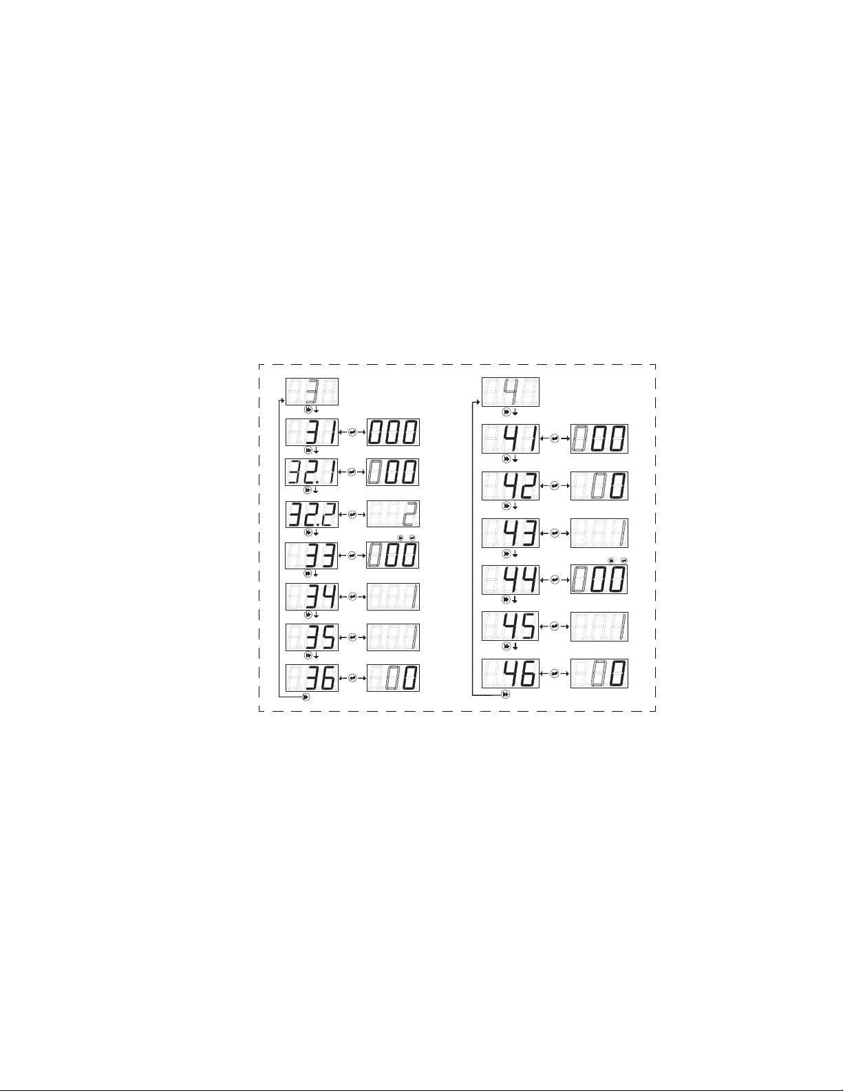
Configuration Settings
Input Installer Password
Detergent Control
1 = Door
2 = Conveyor
Machine Type
1 = Liquid
2 = Capsule
Detergent Type
0-7, Default=4
Pulse Feed
0 = Off 1 = Low
2 = Med. 3 = High
Alarm Volume
Seconds For 1 Rack
Rack Time in Rinse
Initial Charge (Probeless Mode)
Change Installer Password
Demo Mode
Figure 6-2 Program Mode Screens
6-2 P/N 20-06270-00 Rev. N
Page 23

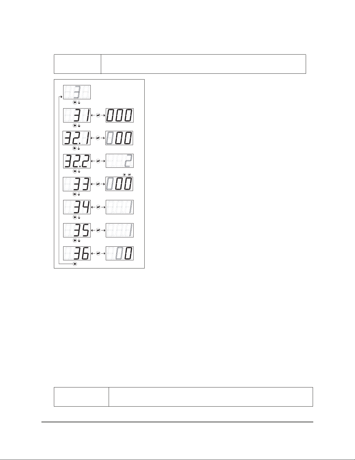
Configuration Settings
The Configuration Settings Menu loop is always available. To simplify programming, only one Adjustment Menu loop is accessible once a Detergent Control selection has been made in Menu 21.
Input Installer Password
Configuration Settings
1 = Probe
Detergent Control
Machine Type
Detergent Type
2 = Probeless
1 = Door
2 = Conveyor
1 = Liquid
2 = Capsule
Pulse Feed
Alarm Volume
Rack Time in Rinse
Initial Charge (Probeless Mode)
Change Installer Password
Demo Mode
0-7, Default = 4
0 = Off 1 = Low
2 = Med. 3 = High
Seconds For 1 Rack
1 = Automatic, 2 = Manual
NOTE: Pulse Feed display is ONLY available when
Detergent Type = Capsule (screen 23.1 = 2).
1= 1 Sec. On, 9 Sec. Off, 50% of Set Point
2= 1 Sec. On, 9 Sec. Off, 70% of Set Point
3= 2 Sec. On, 6 Sec. Off, 50% of Set Point
4= 2 Sec. On, 6 Sec. Off, 80% of Set Point
5= 4 Sec. On, 4 Sec. Off, 70% of Set Point
6= 6 Sec. On, 4 Sec. Off, 80% of Set Point
7= 6 Sec. On, 1 Sec. Off, 90% of Set Point
0= No pulse feed
(Conveyor ONLY)
= Rinse Signal
= Detergent Signal
Figure 6-3 Configuration Settings (Menu 2)
Detergent Control (Menu 21)
This selection determines whether the Probe or Probeless Adjustment Menu is available.
1. Press
2. Press
3. Press
ENTER to view/change this setting.
SCROLL to select between 1 (Probe) or 2 (Probeless) detergent control.
ENTER to set the value and return to the main menu loop.
Machine Type (Menu 22)
1. Press ENTER to view/change this setting.
2. Press
3. Press
P/N 20-06270-00 Rev. N 6-3
SCROLL to select between 1 (Door) or 2 (Conveyor) machine type.
ENTER to set the value and return to the main menu loop.
Page 24

Detergent Type (Menu 23.1)
1. Press ENTER to view/change this setting.
2. Press
3. Press
SCROLL to select the detergent type. Select 1 (Liquid) or 2 (Capsule). This sets the feed and
read ratio when the concentration is within 20% of set point. The detergent set points are:
• 1 (Liquid) = 3 seconds on/3 seconds off
• 2 (Capsule) = 2 seconds on/6 seconds off
ENTER to set the value and return to the main menu
Note
#
If 1 (Liquid) is selected and the unit is equipped with a solenoid valve, the display
indicates a pump jam condition and the dispenser will not activate the solenoid valve.
Pulse Feed – Capsule Detergent Only (Menu 23.2)
This screen is displayed only if screen 23.1 (Detergent type) is set to 2 (Capsule). Use this menu to
adjust the length of time that the detergent feeds (the pulse) and the interval between pulses, based
upon detergent strength and the distance between the product container and dish machine.
1. Press
2. Press
ENTER to view/change this setting.
SCROLL to change the value (0-7).
The settings are as follows:
1 = 1 Second on, 9 Seconds off, @ 50% of set point
2 = 1 Second on, 9 Seconds off, @ 70% of set point
3 = 2 Seconds on, 6 Seconds off, @ 50% of set point
4 = 2 Seconds on, 6 Seconds off, @ 80% of set point (Default)
5 = 4 Seconds on, 4 Seconds off, @ 70% of set point
6 = 6 Seconds on, 4 Seconds off, @ 80% of set point
7 = 6 Seconds on, 1 Second off, @ 90% of set point
0 = No pulse feed
3. Press
ENTER to set the value and return to the main menu loop.
Alarm Volume (Menu 24)
1. Press ENTER to view/change this setting.
2. Press
SCROLL to select between 0 (Off), 1 (Low), 2 (Medium), or 3 (High) alarm volume.
A half-second beep will sound for each level as the Scroll key is pressed.
3. Press
ENTER to set the value and return to the main menu loop.
Rack Time in Rinse (Menu 25)
Note
#
To determine this value, time the number of seconds it takes the dish machine conveyor to move one
rack a single rack length’s distance through one complete rinse cycle. Input that time in Menu 25.
1. Press
2. Press
3. Press
6-4 P/N 20-06270-00 Rev. N
ENTER to view/change this setting.
SCROLL to change the value of the blinking center digit (tens).
NEXT to move to the right digit (ones), which then begins blinking.
This menu applies only to conveyor-type dishwashers. The value that is set is used
to count racks and determine detergent dose intervals, if set to Probeless Mode.
Page 25

4. Press SCROLL to change the value of the blinking right digit (ones). The range is 0 - 29 seconds.
5. Press
ENTER to set the value and return to the main menu loop.
Initial Charge - Probeless Only (Menu 26)
Note
#
This menu applies only to probeless detergent control. and has no effect when
probe detergent control is selected in menu 21.
This setting determines whether the Initial Charge is Manual or Automatic. To set the initial charge:
1. Press
2. Press
3. Press
ENTER to view/change this setting.
SCROLL to select between 1 (Automatic) or 2 (Manual) initial detergent charge.
ENTER to set the value and return to the main menu loop.
Manual Initial Charge
To start a Manual Initial Charge from the User Mode, press SCROLL.
Automatic Initial Charge
In a door-type dishwasher, the Automatic Initial Charge occurs each time the dispenser receives a
rinse signal that was not preceded by a detergent signal within 90 seconds prior (i.e. on an initial fill).
When this condition occurs, the dispenser detects an Automatic Initial Charge, disables the rinse feed,
and feeds detergent for the time that is set in Menu 41. (See “Detergent I nitial Charge (Menu 41)” on
page 6-9 for more information.) Normal rinse signal activations (within 90 seconds after a detergent
signal) will not generate an initial charge.
A five minute lockout timer begins at the start of initial charge; this prevents an additional initial
charge from occurring if multiple rinse signals are detected during fill.
In a
conveyor-type dishwasher
detergent signal input that has been present for 10 seconds continuously. Then, the rinse pump is turned
off for 90 seconds (or Detergent Initial Charge time, if longer), and the detergent feeds for the time that
is set in Menu 41(see
“Detergent Initial Cha rge (Menu 41)” on page 6-9
It is important to note that this will happen each time a detergent signal occurs, so the source of this
signal must remain on for the entire time the tank is full, or not occur more than one time per machine
fill. (See Chapter 2 “Electrical Installation” for more information.)
, the Automatic Initial Charge occurs each time the dispenser detects a
for more information.)
Change Installer Password (Menu 27)
Caution
,
1. Press ENTER to view/change this setting. Any three-digit number may be input.
2. Press
3. Press
4. Press
SCROLL to change the blinking digit to the desired value.
NEXT to move the blinking digit. Repeat for all digits.
ENTER to set the value and return to the main menu loop.
Be sure to note the new password if you change it from the factory setting (123).
If your password is lost, contact Nova Controls Customer Service.
Demo Mode (Menu 28)
This menu is used to test or demonstrate dispenser functions.Press ENTER to access or exit demo
mode. Press
P/N 20-06270-00 Rev. N 6-5
NEXT to simulate Rinse Signal or SCROLL to simulate Detergent Signal.
Page 26
Adjustments—Probe Mode (Menu 3)
Note
#
Adjustments—Probe Mode
Detergent Tank Reading Tank Reading
Detergent Set Point Set Point 0-999
Live Conductivity Display
Rinse Pump Speed
Low Detergent Alarm Delay
Rinse Feed Opt (Door Only)
This menu is only available when Detergent Control (menu 21) is set to 1 (Probe).
1=Yes, 2=No, (Default)
+
0-59.5 RPM,
# of Racks (1-9)
1 = Rinse on rinse
2 = Rinse on detergent
= Test
0-19 SecondsRinse Delay Time (Door Only)
Figure 6-4 Adjustments - Probe Mode (Menu 3)
Detergent Tank Reading (Menu 31)
Prepare for this reading by manually adding product to proper concentration, then test via titration or
measured volume. The dishwasher tank solution must be well mixed (wash pump running) and at
operating temperature.
Press
ENTER to view this number, which is an average that is updated every 0.1 seconds.
Make note of the tank reading displayed. This is your set point.
Detergent Set Point (Menu 32.1)
1. Press ENTER to view/change this setting and to input the number noted in Menu 31:
2. Press
3. Press
4. Press
SCROLL to change the blinking digit to the desired value.
NEXT to move the blinking digit. Repeat for all three digits. The range is 0 - 999.
ENTER to set the value and return to the main menu.
Note
#
It is good practice to run a few racks through the dish machine & retest concentration
with a titration kit. If the concentration is not at the desired level, adjust accordingly.
6-6 P/N 20-06270-00 Rev. N
Page 27

Live Conductivity Display (Menu 32.2)
1. Press ENTER to view/change this setting.
2. Select 1 to enable the Live Conductivity Display and 2 to disable this display.
The default is 2 (disabled).
Rinse Pump Speed (Menu 33)
Note
#
Adjust the rinse pump speed for appropriate amount of product needed for
good results on wares.
To determine this adjustment, note the amount of rinse product per unit of water (check the dish
machine specifications for rinse water flow rate per minute) or observe the sheeting action of the product on wares. With the standard rise pump tube, the Sprite will dispense 0.5 ml per revolution.
To test run or view the rinse pump speed, press and hold the Next key, followed by the Enter key.
The pump will run at the current speed setting.
To change the rinse pump speed:
1. Press
2. Press
3. Press
ENTER to view/change this setting.
SCROLL to change the blinking digit to the desired value.
NEXT to move the blinking digit. Repeat for all digits.
The range of this adjustment is from 0 to 59.5 RPM in 0.5 RPM steps.
4. Press
ENTER to set the value and return to the main menu loop.
Low Detergent Alarm Delay (Menu 34)
This setting determines how many racks can run before the Low Detergent Alarm is activated.
1. Press
2. Press
3. Press ENTER to set the value and return to the main menu loop.
ENTER to view/change this setting.
SCROLL
to select the number of racks (1-9) allowe d to run with a low det er gent con centration .
Note
#
The low detergent alarm will occur only if there is no increase in detergent
concentration and the unit is below set point for the number of racks set.
The low detergent alarm resets itself when it detects a rise in detergent
concentration.
Rinse Feed Option (Menu 35)
The setting determines when the rinse feed is activated.
1. Press
2. Press
3. Select option
4. Select option
5. Press
P/N 20-06270-00 Rev. N 6-7
ENTER to view/change this setting.
SCROLL to select rinse feed option (1 or 2).
1 to run the rinse pump each time the rinse signal activates (for the duration of time
the signal is present).
2 to run the rinse pump for a fixed time of 12 seconds each time the detergent signal
activates.
ENTER to set the value and return to the main menu loop.
Page 28

Rinse Delay Time (Menu 36)
Note
#
This menu is available only when:
• 1 (Door) is selected in menu 22 (Machine Type) and
• 1 (Rinse on rinse) is selected in menu 35 (Rinse Feed Option)
Use this feature to minimize rinse product waste by injecting product only during the last few seconds
of each rack.
1. Press
2. Press
3. Press
ENTER to view/change this setting.
SCROLL to change the blinking digit to the desired time in seconds.
NEXT to move the blinking digit. Repeat for both digits.
The range of this adjustment is from 0 - 19 seconds.
4. Press
ENTER to set the value and return to the main menu loop.
Adjustments—Probeless Mode (Menu 4)
Note
#
Adjustments—Probeless Mode
Detergent Initial Charge 0-199 Seconds
This menu is available only when menu 21(Detergent Control) is set to 2 (Probeless).
Detergent Dose
Detergent Dose Interval Racks (1, 2 or 3)
Rinse Pump Speed
Rinse Feed Opt (Door Only)
0-19 Seconds
0-59.5 RPM,
1 = Rinse on rinse
2 = Rinse on detergent
0-19 SecondsRinse Delay Time (Door Only)
+
= Test
Figure 6-5 Adjustments - Probeless Mode
6-8 P/N 20-06270-00 Rev. N
Page 29

Detergent Initial Charge (Menu 41)
Note
#
Prepare for this reading by determining the detergent feed time (in seconds)
required to charge the wash tank to the correct concentration on an initial fill.
1. Press ENTER to view/change this setting and to input the initial charge detergent feed time.
2. Press
3. Press
4. Press
SCROLL to change the blinking digit to the desired value.
NEXT to move the blinking digit. Repeat for all three digits. The range is 0 - 199 seconds.
ENTER to set the value and return to the main menu loop.
Detergent Dose (Menu 42)
Note
#
This setting determines the amount of detergent that is dispensed in each dose.
1. Press
2. Press
3. Press
4. Press
ENTER to view or input the detergent recharge dose feed time.
SCROLL to change the blinking digit to the desired value.
NEXT to move the blinking digit. Repeat for all three digits. The range is 0 - 19 seconds.
ENTER to set the value and return to the main menu loop.
The detergent dose time depends on the detergent dose interval set in Menu 43.
The available dose intervals are every rack, every second rack, or every third rack.
Detergent Dose Interval (Menu 43)
This setting determines when a detergent dose occurs.
In conveyor-type dishwashers, a detergent dose will occur when the accumulated Rinse On time
(whether the time accrues continuously or with interruptions) is equal to the rack time multiplied by
the detergent dose interval selected by the user. In conveyor-type dishwashers, the rack time is set in
“Rack Time in Rinse (Menu 25)” on page 6-4.
In door-type dishwashers, a “rack” is counted each time the door is opened and closed.
1. Press
2. Press
ENTER to view/change this setting.
SCROLL to select the rack interval between detergent doses.
The available dose intervals are: every rack; every second rack; or every third rack.
3. Press
ENTER to set the value and return to the main menu loop.
P/N 20-06270-00 Rev. N 6-9
Page 30

Rinse Pump Speed (Menu 44)
Note
#
Adjust rinse pump speed for the appropriate amount of product required to achieve
good results on wares.
To determine this adjustment, note the amount of rinse product per unit of water (check the dish
machine specifications for rinse water flow rate per minute), or observe the sheeting action of the product on wares. With the standard size rinse pump tube, the Sprite will dispense 0.5 ml per revolution.
To test run/view the rinse pump speed, press and hold NEXT, followed by ENTER, and the pump will
run at the current speed setting.
1. Press
2. Press
3. Press
ENTER to view/change this setting.
SCROLL to change the blinking digit to the desired value.
NEXT to move the blinking digit. Repeat for all digits.
The range is 0 - 59.5 RPM in 0.5 RPM steps.
4. Press
ENTER to set the value and return to the main menu loop.
Rinse Feed Option (Menu 45)
This setting determines when rinse product will be dispensed.
1. Press
2. Press
3. Press
ENTER to view/change this setting.
SCROLL to select rinse feed option (either 1 or 2 as described below).
• Select 1 to run the rinse pump (and detergen t dose on the selected dose intervals) each time the
rinse signal activates (for the entire time the signal is present).
• Select 2 to run the rinse pump for a fixed time of 12 seconds (and deter gent dose on the selected
dose intervals) each time the detergent signal activates.
ENTER to set the value and return to the main menu loop.
Rinse Delay Time (Menu 46)
This feature minimizes waste by injecting rinse product only during the last few seconds of each rack.
Note
#
1. Press
2. Press
3. Press
4. Press
ENTER to view/change this setting.
SCROLL to change the blinking digit to the desired time in seconds.
NEXT to move the blinking digit. Repeat for both digits. The range of this adjustment is from
0 to 19 seconds.
ENTER to set the value and return to the main menu loop.
This menu is available only when:
• 1 (Door) is selected in menu 22 (Machine Type) and
• 1 (Rinse on rinse) is selected in menu 35 (Rinse Feed Option).
6-10 P/N 20-06270-00 Rev. N
Page 31
Troubleshooting
Overview
This chapter describes the troubleshooting displays and methods for the Sprite, including:
• Alarms and Indicators
• Preliminary Checks
• No Display
• No Detergent Feed (Probe and Probeless Modes)
• Excess Detergent Consumption (Probe and Probeless Modes)
• No Rinse Feed (Probe and Probeless Modes)
Alarms and Indicators
The following display indicators, seen in the User Mode, provide useful information for troubleshooting
purposes:
7
Detergent Signal On
Figure 7-1 User Mode Alarms and Status Indicators
Probe Mode Active
Rinse Signal On
Detergent Pump Jammed
Rinse Pump Jammed
Preliminary Checks
If unit is dead, no display, go directly to Dead Unit (No Display). Otherwise, check the indicators and
alarms for information about the dispenser.
Dead Unit (No Display)
• Confirm main power connection voltage with a volt meter.
• Check fuse if optional fuse kit is installed.
• Substitute transformer followed by the printed circuit board to determine fault
P/N 20-06270-00 Rev. N 7-1
Page 32

No Detergent Feed
• For either Probe or Probeless Modes, confirm that detergent type (screen 23) is set correctly.
Probe Mode
• Temporarily disconnect probe wire (with detergent signal on) to force detergent feed.
- If detergent feeds, check for probe scaling and check detergent setpoint setting.
- If detergent does not feed, replace pump motor (or solenoid coil), then printed circuit board.
Probeless Mode
• Confirm that unit is in a detergent feed condition as determined by rinse/initial charge signal inputs
and initial charge/dose adjustments.
• If detergent does not feed, substitute pump motor (or solenoid coil), followed by the printed circuit
board to determine fault.
Excess Detergent Consumption
Probe Mode
• Check probe for scaling.
• Measure wash solution via titration kit or other means. If detergent is at proper concentration,
check the dish machine for clogged drains, excessive fresh water feedback, etc.
Probeless Mode
• Confirm that initial charge is dispensed only one time per initial fill. If you experience multiple
initial charge feeds (Automatic/Conveyor mode only), review initial charge wiring connection.
• All other modes, adjust initial charge and dose adjustments accordingly.
No Rinse Feed
The unit is programmed to lock out the rinse feed under certain conditions. Check for the following conditions:
• Probeless/Door/Automatic Initial Charge modes—Rinse is locked out after Initial Charge begins
until the following rack (rinse signal) occurs.
• Probe Mode—Detergent signal did not occur within 90 seconds prior to rinse signal (Rinse Saver
feature).
If the problem is not in one of the above conditions and rinse does not feed, substitute pump motor, followed by the printed circuit board, to determine fault.
7-2 P/N 20-06270-00 Rev. N
Page 33

Maintenance and Service
Overview
This chapter describes the maintenance and service for the Sprite, including a list of spare parts:
• Routine Maintenance
• Maintenance Visits
• Pump Tube Replacement
• Service Disassembly
• Lower Cabinet Front Removal
• Upper Cabinet Front Removal
• Diagram of Unit Parts
• Spare Parts Listing
Maintenance
8
Routine maintenance on the Sprite unit includes:
• Keeping the probe clean (probe mode operation only)
• Keeping pump tubes fresh
• Keeping the unit clean
Repairs to the unit involves modular component replacement. This minimizes spare parts inventory
requirements and speeds up the service process in the field.
Every Maintenance Visit
• Titrate the wash tank solution to verify that unit is holding accurate concentration.
• Clean probe, if required.
• Clean the unit cabinet with a damp cloth.
• Check the pump tube's condition and replace, if needed.
Pump Tube Replacement
Replace pump tubes at regular maintenance intervals, well before the tube fails and ruptures. If the tube
does rupture, clean all product from the pump with a damp cloth.
• Loosen the pump front captive screw and remove the pump front.
• Remove the old tube with barbed connectors.
• Install the new tube with barbed connectors oriented with flat sides facing towards the front.
• Insert new tube from left side of pump, with pump spinner oriented in an 11/1 o'clock position.
• Turn the spinner clockwise, using a screwdriver, as you press the pump tube in place.
P/N 20-06270-00 Rev. N 8-1
Page 34

Service Disassembly
Warning
,
Sprite service parts consist of three major assemblies: pump parts, tubes, and the solenoid valve. The three
major field replacement assemblies are:
• Upper Cabinet Front—includes printed circuit board, cabinet front, and cables
• Lower Cabinet Front—includes pump motor(s)
• Cabinet Rear—includes power transformer
Upper Cabinet Front Removal
1. Remove the three front phillips-head screws.
2. Lift upper cabinet front off of unit complete with power and probe wires. (Disconnect solenoid
valve plug from printed circuit board on solenoid equipped units.)
3. Unplug power transformer plug from printed circuit board and remove upper cabinet front.
Lower Cabinet Front Removal
1. Remove the lower front phillips-head screw.
2. Open lower cabinet front by lifting out at the bottom.
3. Lift off front assembly and disconnect motor wire plug(s) from the printed circuit board and
remove Lower Cabinet Front.
Disconnect all power while performing this service or any time unit is opened.
Pump Front Captive Screws
Lower Cabinet Front
Phillips-head Screw
Solenoid Shield
Upper Cabinet Front Screws
Figure 8-1 Sprite Cabinet Assembly
8-2 P/N 20-06270-00 Rev. N
Page 35

Spare Parts
13
12
1
2
3
4
5
6
7
8
14
15
9
10
11
Figure 8-2 Spare Parts Listing
P/N 20-06270-00 Rev. N 8-3
Page 36

Table 8-1 Spare Parts Listing
Ref. Number Part Number Description
1 13-06393-00 Printed Circuit Board, includes Cabinet Front and Terminal Barriers
1 13-06393-01 Printed Circuit Board (European Wire Colors), includes Cabinet Front and Terminal
Barriers
2 30-06358-0832 Cabinet Front Screw
3 13-06394-00 Transformer
4 30-06359-0605 Transformer Screw
5 03-03570-039 Wall Mount Hanger
6 13-06523-01 Pump Motor, Rinse
6 13-06524-01 Pump Motor, Detergent
7 13-06525-00 Lower Cabinet Front (Pump Housing Front)
8 13-06526-00 Cabinet Rear (No On/Off Switch)
8 13-06527-00 Cabinet Rear (With On/Off Switch)
9 13-06397-00 Solenoid Valve Kit, 1/4" Fittings
9 13-06397-01 Solenoid Valve Kit, 6 mm Fittings
9 13-06397-02 Solenoid Valve Kit, 5/16" (8 mm) Fittings
10 30-06359-0605 Solenoid Valve Screw
11 13-06528-00 Solenoid Valve Nut w/ Sleeve, 1/4”, 10 Pack
11 13-06528-01 Solenoid Valve Nut w/ Ferrule, 6mm, 10 Pack
11 13-06528-02 Solenoid Valve Nut w/ Sleeve, 5/16” (8mm), 10 Pack
12 13-06398-00 Pump Front (Includes Captive Screw)
13 13-06396-00 Pump Spinner
14 13-06395-10 Pump Tube, Rinse, EPDM (Includes 1/4" Barb Fittings), 10 pack
14 13-06395-20 Pump Tube, Rinse, EPDM (Includes 1/4" and 1/8" Barb Fittings), 10 Pack
14 13-06395-30 Pump Tube, Rinse, EPDM (Includes 1/8" Barb Fittings), 10 Pack
14 13-06928-10 Pump Tube, Rinse, Silicone (Includes 1/4" Barb Fittings), 10 Pack
14 13-06928-20 Pump Tube, Rinse, Silicone (Includes 1/4" and 1/8" Barb Fittings), 10 Pack
14 13-06928-30 Pump Tube, Rinse, Silicone (Includes 1/8" Barb Fittings), 10 Pack
14 13-06399-10 Pump Tube, Detergent, EPDM (Includes 1/4” Barb Fittings), 10 Pack
15 13-06563-00 Pump Tube Compression Nut w/ Sleeve, 1/4" (10 pack)
15 13-06563-01 Pump Tube Compression Nut w/ Sleeve, 6 mm (10 pack)
15 13-06563-02 Pump Tube Compression Nut and Ferrule, 1/8" or 3 mm (10 pack)
* 13-06529-00 Rinse Injection Fitting, Straight, Kynar, 1/8" NPT x 1/4” Tube
* 13-06529-01 Rinse Injection Fitting, Straight, Kynar, 1/8" NPT x 1/8" (3 mm) Tube
* 13-06529-02 Rinse Injection Fitting, Straight, Kynar, 1/8" NPT x 6 mm Tube
* 13-06531-00 Rinse Injection Fitting, 90° Elbow, Kynar, 1/8" NPT x 1/4” Tube
* 13-06531-01 Rinse Injection Fitting, 90° Elbow, Kynar, 1/8" NPT x 1/8" (3 mm) Tube
* 13-06531-02 Rinse Injection Fitting, 90° Elbow, Kynar, 1/8" NPT x 6 mm Tube
* Denotes items not shown.
8-4 P/N 20-06270-00 Rev. N
Page 37

Specifications
Note
#
Dimensions
Size
Weight 6 lbs. (2.72 kg)
Power Requirements
Total Amperage draw during
operation
General
Rinse Pump Flow Rate 0.5 mls/revolution
Detergent Pump Flow Rate 5.25 oz./min. (156 mls/min)
Environmental
Pollutio n 2
Installation Category II
Temperature 10° to 49° C (50° to 120° F) (max.)
Humidity 95% relative humidity (max.)
Indoor Installation Approved for indoor use only. Must not be installed outdoors.
Altitude Install at or below 6,500 ft. (2000m) max.
Specifications subject to change without notice.
6" W x 10.75" H (w/solenoid) x 4.88" D
(15.24 cm W x 27.31 cm H x 12.38 cm D)
90 to 130 VAC nominal, 50/60 Hz., 0.5 amps (max.)
200 to 249 VAC nominal, 50/60 Hz., 0.3 amps (max.)
9
P/N 20-06270-00 Rev. N 9-1
Page 38

Limited Warranty
SELLER warrants solely to BUYER the Products will be free from defects in material and workmanship under normal use and service for a period of one year from the date of completion of
manufacture. This limited warranty does not apply to (a) hoses; (b) and products that have a normal life shorter than one year; or (c) failure in performance or damage caused by chemicals, abrasive materials, corrosion, lightning, improper voltage supply, physical abuse, mishandling or
misapplication. In the event the Products are altered or repaired by BUYER without SELLER’S
prior written approval, all warranties will be void.
NO OTHER WARRANTY, ORAL, EXPRESS OR IMPLIED, INCLUDING ANY W ARRANTY
OF MERCHANTABILITY OR FITNESS FOR ANY PARTICULAR PURPOSE, IS MADE
FOR THESE PRODUCTS, AND ALL OTHER WARRANTIES ARE HEREBY EXPRESSLY
EXCLUDED.
SELLER’S sole obligation under this warranty will be, at SELLER’S option, to repair or replace
F.O.B. SELLER’S facility in Watsonville, California any Products found to be other than as
warranted.
Limitation of Liability
SELLER’S WARRANTY OBLIGATIONS AND BUYERS REMEDIES ARE SOLELY AND
EXCLUSIVELY AS STATED HEREIN. SELLER SHALL HAVE NO OTHER LIABILITY,
DIRECT OR INDIRECT, OF ANY KIND, INCLUDING LIABILITY FOR SPECIAL,
INCIDENTAL, OR CONSEQUENTIAL DAMAGES OR FOR ANY OTHER CLAIMS FOR
DAMAGE OR LOSS RESULTING FROM ANY CAUSE WHATSOEVER, WHETHER
BASED ON NEGLIGENCE, STRICT LIABILITY, BREACH OF CONTRACT OR BREACH
OF WARRANTY.
9-2 P/N 20-06270-00 Rev. N
Page 39

Index
A
Adjustments - Probe Mode 6-6
Adjustments - Probeless Mode 6-8
Alarms & Indicators 7-1
Alarms (Probe Mode Only) 5-4
Altitude, allowable for unit 9-1
Automatic Initial Charge 6-5
B
Bulkhead Fitting 2-3, 2-4
C
Cabinet Disassemble 8-2
Cabinet Disassembly 8-2
Change password 6-5
Changing tubes 8-1
Circuit Voltage chars 3-2
Configuration Settings, diagram of screens 6-3
Conveyor-type Dishwashers, initial charge 6-5
Count racks 6-4
D
De-Lime 1-1, 5-3
Detergent 2-2, 6-5, 6-7, 6-8, 6-9, 6-10
concentration 6-7
consumption 7-2
dose intervals 6-4
pump flow rate 9-1
set point 6-6
setting control 6-3
setting the type 6-4
Dimensions 9-1
Discharge 2-4
Door-type Dishwashers, initial charge 6-5
E
External junction box 2-2
H
Humidity, allowable for unit 9-1
I
Initial Charge 3-4, 6-5, 6-9
probeless 6-5
Input Screen 4-1, 5-4
Installation Category 9-1
K
Key Description 4-1
L
Leak-free assembly 2-3
Live Conductivity Display 5-3, 6-7
Low Detergent Alarm 5-4
M
Machine Type, setting 6-3
Maintenance 8-1
Manual Initial Charge 5-4, 6-5
motor 3-3
N
Next Key 4-1
O
Overfeed 5-1
P
Parts, listing of 8-3
Password 5-4, 6-1
Password, changing 6-5
Pollution category 9-1
Power Requirements 9-1
Prime 5-3
Probe 2-2, 3-2, 6-3
adjustment menu 6-6
detergent signal wiring 3-3
maintenance 8-1
placement 2-2
wire 3-1
Probeless 6-8
detergent signal wiring 3-4
Program Mode 4-1, 5-4, 6-1
access with password 6-1
menu screens 6-2
use of keys 4-1
Pump
flow rate 9-1
speed 6-7, 6-10
tube replacement 8-1
Pump Jam display 7-1
R
Rack Counter 5-2
Replacing tubes 8-1
Rinse 6-7
delay 6-8
feed 6-5, 6-7, 6-10
injection 2-4
injection installation 2-3
Rinse Pump 5-1, 6-5, 9-1
discharge tube 2-4
flow rate 9-1
prime 5-3
set run time 6-7
speed 6-7
Rinse Saver 1-1, 6-10
Rinse Signal 6-5, 6-7, 6-10
wiring 3-4
P/N 20-06270-00 Rev. N Index-1
Page 40

S
Scroll key 4-1, 5-4, 6-3, 6-5
set point 6-4
Setting password 6-1
Signal Wiring 3-3
Size of unit 9-1
Solenoid Water Feed installation 2-4
Spare Parts listing 8-3, 8-4
Specifications 9-1
System Diagram 2-1
T
Temperature, allowable for unit 9-1
Titration 8-1
Total Amperage draw 9-1
troubleshooting 7-1
tube connection 2-4
Tube rupture, cleaning 8-1
Tubes, replacing 8-1
U
User Mode 5-1
menus 5-2
use of keys 4-1
W
Wall Mou nt 2 -2
Water supply, with solenoid 2-4
Weight of unit 9-1
Wiring 3-2, 3-3
charts 3-2
connections 3-1
main power diagrams 3-3
Index-2 P/N 20-06270-00 Rev. N
Page 41

Configuration Settings
Input Password to Start
Detergent Control
Machine Type
Detergent Type
Pulse Feed
NOTE: Pulse Feed display is ONLY available when
Detergent Type = Capsule (screen 23.1 = 2).
1= 1 Second On, 9 Seconds Off, 50% of Set Point
2= 1 Second On, 9 Seconds Off, 70% of Set Point
3= 2 Seconds On, 6 Seconds Off, 50% of Set Point
4= 2 Seconds On, 6 Seconds Off, 80% of Set Point (Default)
5= 4 Seconds On, 4 Seconds Off, 70% of Set Point
6= 6 Seconds On, 4 Seconds Off, 80% of Set Point
7= 6 Seconds On, 1 Second Off, 90% of Set Point
20-06270-00N
1 = Probe
2 = Probeless
1 = Door
2 = Conveyor
1 = Liquid
2 = Capsule
0-7 (0 = No pulse feed)
SPRITE Warewash Programming Card
Alarm Volume
Rack Time in Rinse
Initial Charge (Probeless only)
Seconds For 1 Rack
0 = Off
1 = Low
2 = Med
3 = High
Conveyor
Machines Only
1 = Automatic
2 = Manual
A Systems Company
Change Installer Password
225 WESTRIDGE DRIVE
WATSONVILLE
CALIFORNIA
Demo Mode
95076-4168 U.S.A.
TEL 831.786.1470
Exit to User Menu
FAX 831.786.1650
A Systems Company
225 WESTRIDGE DRIVE
WATSONVILLE
CALIFORNIA
95076-4168 U.S.A.
TEL 831.786.1470
FAX 831.786.1650
= Rinse Signal
= Detergent Signal
Page 42
Adjustments,
Probe Mode
Detergent Tank Reading Tank Reading
Adjustments,
Probeless Mode
Detergent Initial Charge 0-199 Seconds
Detergent Set Point
Live Conductivity Display
Rinse Pump Speed
Low Detergent Alarm Delay
Rinse Feed Opt (Door Only)
Set Point 0-999
1=Yes, 2=No, (Default)
+
0-59.5 RPM,
# of Racks, 1-9
1 = Rinse on rinse
2 = Rinse on detergent
0-19 SecondsRinse Delay Time (Door Only)
= Test
Detergent Dose
Detergent Dose Interval Racks (1, 2 or 3)
Rinse Pump Speed
Rinse Feed Opt (Door Only)
0-19 Seconds
0-59.5 RPM,
1 = Rinse on rinse
2 = Rinse on detergent
0-19 SecondsRinse Delay Time (Door Only)
+
= Test
 Loading...