

NOV CA203AC, CA210AA, CA206AA, CA202AA, CA202AB Installation, Operation And Maintenance Instructions
...Page 1

English
Instructions
Installation, Operation
and Maintenance Instructions
Original
Series A Muncher - Mono
OMMP/061/01
Rev 2, October 2018
Page 2

Index
Revisions 3
Spares & Service Contacts 4
Tools 5
ATEX Warning Statements 6
Introduction 7
EC Declaration 8
Installation, Operation & Maintenance Instructions 9
Recommended Lifting Points 15
Wiring Diagram 16
Weights 17
Part Number Reference 19
Coupling Options 20
Torque Tightening Figures 21
Muncher Coding Sheet 22
Dismantling & Assembly 23
Exploded Views 48
Sectional Arrangement 51
Adaptor Stool Coding 52
General Arrangement Drawings 54
2
Page 3

Revisions
Rev.
1 24/01/2017
2 09/10/2018
3
4
5
Date
dd/mm/yy
Reason for Issue
Re-numbered from WD001. Updated EC Declaration &
added Authorised Distributors List
Updated adaptor stool part numbers on page 54. Removed
Distributor pages & added link to website for current
distributors on Spares and Service Contacts page.
Prepared ByChecked ByApproved
By
M. Bailey M. Davies A. Morris
M. Bailey M. Bailey M. Bailey
3
Page 4

Spares and Service Contacts
UK
Spares +44 (0)161 214 2380 (direct line 8.15 am – 5.00 pm)
E-mail [email protected]
Service +44 (0)161 214 2390 (direct line 8.15 am – 5.00 pm)
E-mail [email protected]
Service +44 (0)161 339 9000 (24 hrs)
France
Australia
Melbourne (03) 9773 7777
Sydney (02) 8536 0900
Brisbane (07) 3350 4582
Adelaide (08) 8132 6800
Perth (08) 9320 5800
Darwin (08) 8931 3300
E-mail [email protected]
New Zealand
USA
Houston Spares & Service +1 281 854 0300
Ohio Spares & Service +1 877 486 6966
E-mail [email protected]
China
Distributors
For local distribution, please refer to our website:
www.mono-pumps.com/en-uk/sales_network
4
Page 5

Tools
For servicing and maintenance work on the Muncher the following tools are recommended.
SB Muncher;
Metric Hexagon Keys - Range 6mm-8mm (0.24” - 0.31”)
Metric Spanners - Range 10mm-36mm (0.39” - 1.42”)
Torque Wrench
Series A Muncher;
Metric Hexagon Keys - Range 6mm-8mm (0.24” - 0.31”)
Metric Spanners - Range 10mm-36mm (0.39” - 1.42”)
Torque Wrench
Series F Muncher;
Metric Hexagon Keys - Range 6mm-8mm (0.24” - 0.31”)
Metric Spanners - Range 10mm-36mm (0.39” - 1.42”)
Torque Wrench
NOV Locknut Key - Item No.s MQ F06A 9750, CF F06A 9755 and MM F06A 9760
TR Muncher;
Metric Hexagon Keys - Range 6mm-14mm (0.24” - 0.55”)
Metric Spanners - Range 10mm-36mm (0.39” - 1.42”)
Torque Wrench
Series R Muncher;
Metric Hexagon Keys - Range 5mm-14mm (0.20” - 0.55”)
Metric Spanners - Range 10mm-36mm (0.39” - 1.42”)
Torque Wrench
All equipment should be in good working condition with no signs of excessive wear.
5
Page 6

GRINDERS
Due to the nature and design of grinding and macerating
equipment it is possible that certain objects may enter the
cutters, from the process stream, with the potential to cause
sparking or jamming of the cutter assembly.
Where a grinder unit is to be installed in a potentially explosive
atmosphere ensure that this has been specifi ed at the time
of purchase and that the equipment has been supplied
accordingly and displays an ATEX nameplate or is supplied
with a certifi cate of conformity. If there is any doubt as to the
suitability of the equipment please contact your Supplier before
commencing with installation and commissioning.
Process liquids or fl uids should be kept within specifi ed
temperature limits otherwise the surface of grinder or
system components may become an ignition source due to
temperature rises. Where the process liquid temperature is
less that 90ºC (194ºF) the maximum surface temperature will
not exceed 90ºC (194ºF) provided the grinder is installed,
operated and maintained in accordance with this manual.
Where the process fl uid temperature exceeds 90ºC (194ºF)
the maximum surface temperature will be equal to the
maximum process fl uid temperature.
Cavities that could allow the accumulation of explosive gases,
such as under guards, should where possible, be designed out
of the system. Where this is not possible they should be fully
purged before any work is carried out on the grinder or system.
Electrical installation and maintenance work should only be
carried out by suitably qualifi ed and competent persons and
must be in accordance with relevant electrical regulations.
All electrical equipment, including control and safety devices,
should be suitably rated for the environment in to which they
are installed.
Where there may be a risk of an accumulation of explosive
gases or dust non-sparking tools should be used for
installation and maintenance.
To minimise the risk of sparking or temperature rises due to
mechanical or electrical overload the following control and
safety devices should be fi tted. A control system that will shut
the grinder down if the motor current or temperature exceed
specifi ed limits or a jam of the cutter stack occurs. This
may include a system that reverses the machine in order to
clear any such jam. An isolator switch that will disconnect all
electrical supply to the motor and ancillary electrical equipment
and be capable of being locked in the off position. All control
and safety devices should be fi tted, operated and maintained
in accordance with the manufacturer’s instructions.
It is important that the grinder rotates in the correct direction
to give an effi cient grinding operation. This must be checked
on installation and commissioning and after any maintenance
has been carried out. Failure to observe this may lead to
mechanical or electrical overload.
When fi tting drives, couplings, and guards to a grinder unit it is
essential that these are correctly fi tted, aligned and adjusted
in accordance with the O&M instructions. Failure to do so may
result in sparking due to unintended mechanical contact or
temperature rises due to mechanical or electrical overload.
Mechanical seals should be suitably rated for the environment.
The seal and any associated equipment, such as a fl ushing
system, must be installed, operated and maintained in
accordance with the manufacturer’s instructions.
Where a packed gland seal is fi tted this must be correctly fi tted
and adjusted. This type of seal relies on the process liquid to
cool the shaft and packing rings so a constant drip of liquid
from the gland section is required. Where this is undesirable
an alternative seal type should be fi tted.
Failure to operate or maintain the grinder and ancillary
equipment in line with the manufacturer’s instructions may lead
to premature and potentially dangerous failure of components.
Regular inspection, and where necessary replacement,
of bearings, seals, other wearing parts and lubrication is
essential.
The grinder and its components have been designed to ensure
safe operation within the guidelines covered by legislation.
Accordingly your Supplier has declared the machine safe
to use for the duty specifi ed as defi ned by the Declaration
of Incorporation or Conformity that is issued with this
instruction manual. The use of replacement parts that are not
manufactured by or approved by your Supplier may aff ect the
safe operation of the grinder and it may therefore become a
safety hazard to both operators and other equipment. In these
circumstances the Declaration provided will become invalid.
The guarantee referenced on the Terms and Conditions of
Sale will also be invalidated.
6
Page 7

Inroduction
This information and all the information contained herein,
are the exclusive property of your Supplier, and contain
information of a proprietary nature. It is provided for the sole
purpose of transmitting the information contained to the
designated recipient.
This information is to be used only as specied in the
instrument of transmittal. It is not to be reproduced, copied
in whole, or in part, nor is information it contains to be
disclosed in any manner without the written consent of your
Supplier. Its use for any other reason than the specied
shall be a violation of the agreement with the recipient
concerning the legal rights of your Supplier.
Your Supplier reserves the right to make changes, which
may obsolete certain parts of this manual.
The manual gives a guide to the operation and maintenance
of the Muncher given that all Health and Safety and good
engineering practices are observed.
7
Page 8

EC Declaration as defi ned by Machinery Directive 2006/42/EC.
EC Declaration
The following harmonised standards are applicable: BS EN ISO 12100: 2010
EC Declaration of Incorporation
This declaration is only valid when partly completed machinery
has been supplied.
In this case, the machinery meets the requirements of the said
directive and is intended for incorporation into other machinery
or for assembly with other machinery in order to constitute
relevant machinery as defi ned by the said directive including
any amendments, which are valid at the time of supply.
IMPORTANT
This machinery must not be put into service until the relevant
machinery into which it is to be incorporated has been
declared in conformity to the said directive.
This declaration is only valid when the machinery has been
installed, operated and maintained in accordance with these
instructions and safety guidelines contained within as well
as instructions supplied for equipment assembled with or
intended for use with this equipment.
EC Declaration of Conformity
This declaration is not valid for partly completed machinery
that has been supplied.
In this case the machinery meets the requirements of the said
directive including any amendments which are valid at the time
of supply.
We further declare that, where applicable, said machinery also
meets the requirements of:
The EMC Directive 2014/30/EU
The Low Voltage Directive 2014/35/EU
The Pressure Equipment Directive 2014/68/EU
IMPORTANT
This declaration is only valid when the machinery has been
installed, operated and maintained in accordance with these
instructions and safety guidelines contained within as well
as instructions supplied for equipment assembled with or
intended for use with this equipment.
Mr A. Morris - Director of Pump Technology for
NOV PFT UK Ltd., Greengate Way, Middleton,
Manchester, England, M24 1SA.
8
Page 9
Lift
Correctly
Intallation, Operation & Maintenance
1.0 INSTALLATION
1.1 INSTALLATION & SAFETY RECOMMENDATIONS
In common with other items of process plant a Muncher
must be installed correctly to ensure satisfactory and
safe operation. The Muncher must also be maintained to
a suitable standard. Following these recommendations
will ensure that the safety of personnel and satisfactory
operation of the Muncher is achieved.
1.1.1 OPERATING PRINCIPLE
The Muncher is a slow speed, high torque grinder
designed to operate in the water, waste and biowaste
industries. All Munchers have two shafts operating at
diff erential speeds. Each shaft is fi tted with identical
interleaving cutters and spacers.
1.2 GENERAL
When handling harmful or objectionable materials,
adequate ventilation must be provided in order to
disperse dangerous concentrations of vapours. It is
recommended that wherever possible, your Supplier’s
Munchers should be installed with provision for adequate
lighting, thus ensuring that eff ective maintenance can be
carried out in satisfactory conditions. With certain product
materials, a hosing down facility with adequate draining
will simplify maintenance and prolong the life of the
Muncher components.
1.3 SYSTEM DESIGN AND INSTALLATION
At the system design stage, consideration must be given
to the provision of fi ller plugs, and the installation of non-
return and/or isolating valves where applicable.
Series ‘F’ AND ‘H’ Munchers are horizontal dry waste
machines and must be fi xed rigidly and horizontally either
to the ground, or to a rigid system.
TR Pipeline models are designed for horizontal
installation only.
Series ‘A’, SB and ‘R’ open channel models do not require
fi xing to the ground and can be supported either by
the concrete channel or by steel supports bolted to the
concrete channel walls.
Series ‘A’, SB and ‘R’ pipeline models can be installed at
any altitude.
Pipework to and from the unit should be independently
supported and not rely on the Muncher as a means of
support. Wherever possible when installed in a vertical
pipe system the Muncher unit should be independently
supported.
1.4 HANDLING
During installation and maintenance, attention must be
paid to the safe handling of all items. Where a Muncher
or its components weigh in excess of 20kg (45Ib) it is
recommended that suitable lifting tackle should be used
to ensure that personal injury or damage to components
does not occur.
Lifting illustrations are contained in this document on
page 13.
A weight table is included on pages 17 and 18.
NOTE
DO NOT ATTEMPT TO LIFT MUNCHER USING ONLY
ONE LIFTING LUG. EXTREME CAUTION SHOULD
BE OBSERVED FOR PERSONNEL SAFETY WHEN
LIFTING HEAVY OBJECTS.
BY DESIGN THE CUTTERS HAVE SHARP EDGES.
GREAT CARE MUST BE TAKEN WHEN HANDLING.
THE USE OF PROTECTIVE GLOVES IS
RECOMMENDED.
1.5 STORAGE
Munchers are dispatched from our factory with the cutter
chamber sprayed with a moisture repellent coating and
ready for immediate installation and operation.
Should the machine be stored or left stationary for any
length of time it is recommended that the cutter bank is
re-sprayed with anti-rust lubricant and that the shafts are
rotated monthly.
Removing the motor cowl and turning the fan by hand is
the easiest way to rotate the shafts.
Failure to do this may result in a higher frequency of
reversals and in extreme cases the machine to seize due
to the tight running clearances of the individual cutting
elements during commissioning and initial start-up.
The starter panel if supplied should be stored in a
controlled dry environment to prevent moisture buildup causing corrosion of contactors and other metallic
components.
See manufacturer instructions for motor/gearbox/drive
and panel storage procedures.
NOTE:
The Muncher must be protected by a PLC control unit
set up to the correct operating philosophy. Only PLC’s
supplied or approved by your Supplier should be used.
Failure to observe this requirement may cause premature
9
Page 10
machine failure and could invalidate the warranty of the
machine. It is also important that the PLC be correctly
wired into the panel.
Please refer to Wiring Diagram on page 16.
GUARDS
In the interests of safety, and in accordance with relevant
legislation, all guards must be replaced after necessary
adjustments have been made.
IMMEDIATELY PRIOR TO INSTALLATION AND STARTING
Before installing the Muncher please ensure that all plugs
and inspection plates are replaced.
For TR Munchers please see section 1.9.1 prior to
starting for instructions on how to fi t constant level oilers.
1.6 ELECTRICAL
Electrical connection should only be made using
equipment suitable for both rating and environment.
Where any doubts exist regarding the suitability of
equipment, your Supplier should be consulted before
proceeding.
Earthing points will be provided on electric drives (if
supplied) and it is essential that these are correctly
connected. The electrical installation should include
appropriate isolating equipment to ensure that the unit is
safe to work on.
1.7 GENERAL SAFETY
GREAT CARE MUST BE TAKEN TO PROTECT ALL
ELECTRICAL EQUIPMENT FROM SPLASHING WHEN
must be used
SUPPLIED A BASIC MUNCHER THE ONUS IS ON THE
HOSING DOWN. WHERE YOUR SUPPLIER HAS
Guards
USER TO FIT ADEQUATE GUARDS IN COMPLIANCE
WITH THE REQUIREMENTS OF THE RELEVANT
REGULATIONS.
All nuts and bolts, securing fl anges and base mounting
fi xtures must be checked for tightness before operation.
When commissioning the plant, all joints in the system
must be checked thoroughly for leakage.
If, when starting, the Muncher does not appear to operate
correctly, the plant must be shut down immediately
and the cause of the malfunction established before
operations are recommenced.
May contain substances from the ECHA SVHC
Candidates List (REACH - Regulation (EC) No.
1907/2006)
NOTE:
NEVER inspect or work on or near the cutter chamber
without fi rst isolating and locking the machine.
It is strongly recommended that a Series ‘F’ or ‘H’ ONLY
horizontal dry Muncher system should incorporate: -
Guards
must be used
a) A steel (or similar) feed hopper with a minimum base to
top height of 1.0 metre (3.3 feet) or a minimum height
of 1.5 metres (4.9 feet) from fl oor level.
b) A steel (or similar) lower delivery chute, which is
inaccessible without tools.
c) A protective grid mounted over the Muncher and
conveyor system, especially where overhead walkways
are present.
d) Emergency stop buttons positioned within easy reach
of all operating staff .
The recommended extent of enclosure is illustrated in this
document on page 52 onwards (Series F or H ONLY).
1.7.1 WARNING /CONTROL DEVICE
Prior to operating the Muncher, if any warning or control
devices are fi tted these must be set in accordance with
their specifi c instructions.
1.7.2 NOISE LEVELS
The noise sound pressure level will not exceed 70dB at
one metre distance from the Muncher. This is based on
must be used
noise from other sources or any contribution from building
a typical installation and does not necessarily include
Guards
reverberation.
1.8 EXPLOSIVE PRODUCTS/ HAZARDOUS
ATMOSPHERES
In certain instances the product being treated may well be
of a hazardous nature.
In these installations consideration must be given to
provide suitable protection and appropriate warnings to
safeguard personnel and plant.
1.9 LUBRICATION
The gearmotor(s) is supplied with the correct type and
quantity of lubricant in the gearbox but should be checked
before use. For further data see separate information
supplied by manufacturer.
Series ‘F’ and ‘H’ bearings and rotary shaft seals are
lubricated via greasing points on each bearing housing.
The correct quantity of grease is reached when excess
10
Page 11
can be seen around the outer lipseal. Other models have
sealed for life bearings that do not require maintenance.
long as there is oil visible in the oiler then the seals will be
quenched with oil
Gears should be inspected periodically to see if grease
replenishment is necessary, and if so, grease should be
added via the grease nipple until the housing is two thirds
full.
Only use recommended lubricant shown below for
Muncher shaft gears, bearings and rotary seals.
BP Energrease LC2 (-30°C to 180°C) (-22°F to 356°F).
At the following intervals, bearings, gears and seal
assembly inspection should take place along with
lubricant replenishment;
Series ‘F’, ‘H’, ‘R’ - 7,500 hrs
Series ‘A’, SB, TR - 10,000 hrs
PIPELINE MUNCHERS SHOULD BE ISOLATED BY
CLOSING LINE VALVES PRIOR TO SERVICING.
Under tropical or other arduous conditions, however,
more frequent lubrication may be necessary. It is
therefore advisable to establish a suitable maintenance
schedule or periodic inspection to match service
conditions.
2.0 START-UP PROCEDURE
By the nature of the equipment and its operating
environment the Muncher can be an extremely dangerous
machine. It is vital that operators are conversant with
these Operation and Maintenance Instructions prior to
working with the machine.
Where applicable:
1) Check the foundation bolts are secure once the
machine is installed in its correct operating position.
2) Check the gearbox lubricant, remove the plug and fi t
the air vent to prevent gearbox pressurisation. Not
applicable to submersible drive units.
3) Check all electrical connections for continuity and
earthing and that installation is in accordance with
relevant regulations and circuit diagrams.
4) If a feed hopper is fi tted, check that it is secure and
installed correctly, and that no personnel can gain
access to the moving parts of the machine.
1.9.1 All CT203 & CT205 TR Munchers require 2 constant
level
oilers to be fi tted to the bearing housing in order
to prevent the mechanical seals dry-running. The oilers
will be supplied loose with the Muncher to avoid damage
during transit, so upon receipt of the equipment they will
need to be installed prior to operation. Instructions for
fi tting the oilers are as follows:
● Completely fi ll the two mechanical seal cavities through
the upper ¼” BSP ports on the bearing housing as per
lubrication schedule so that no air is left surrounding
the mechanical seals. The two cavities are connected
however it may be necessary to fi ll with oil through
both ports due to the intricate path between the two
mechanical seal cavities.
● Before attaching the oilers to the bearing housing,
ensure the ¼” male nipple is fi tted to each oiler and
proceed to completely fi ll the oilers as per lubrication
schedule
● Attach the oilers to the ¼” BSP ports and tighten until
no oil leaks from the connection.
● Note the level of oil in the oiler and regularly check the
oilers to ensure they have not emptied.
Because mechanical seals do have an expected leak rate
the oilers will need to be re-fi lled with oil periodically. The
precise level of oil in the oilers is not critical because as
Guards
must be used
5) Always ensure that machine is guarded in accordance
with PD5304: 2000 Safety of Machinery requirements
before any attempt is made to operate.
6) Prior to start up ensure all CT203 & CT205 TR
Munchers have constant level oilers fi tted as per
section 1.9.1.
7) On start-up check the direction of rotation of the
cutters. The cutters should rotate towards the centre
when viewed from the inlet side.
NOTE:
If it is necessary to remove any inspection cover to
observe the action – EXTREME CARE should be
observed when carrying out this procedure.
8) Check that the Muncher stops when “STOP” button(s)
are activated.
9) Check for reverse rotation of cutters when “REVERSE”
button is activated.
10) Start up the machine. On initial start-up, allow
machine to run for approximately 45 minutes.
11) Start the feed system to the machine. Care should
be taken not to overburden the machine. Adjust feed
to maintain only the smallest practical reservoir of
material in cutter banks.
11
Page 12

12) After a further 10 minutes of running, stop the
machine, switch off and lock the main isolator. Check
the tightness of all securing bolts. Recheck every 500
hours of operating time.
13) Check the tightness of all cables and connections.
Re-check every 500 hours of operating time.
14) Observe manufacturers guidelines with regard to
gearbox lubricant initial renewal and subsequent
intervals.
15) In the event of machine overload (jam), the controller
is programmed to activate the following procedure:-
i) Momentarily reverse rotation to clear the condition,
then return to normal operation
ii) If overload re-occurs within 60 seconds, reverse
rotation to clear the condition, then return to normal
operation.
iii) If a third overload occurs within 60 seconds of
the fi rst, machine shutdown in reverse mode and
energise alarm circuit.
16) After machine shutdown, isolate and lock off . Inspect
machine, removing any obstruction and press the
“RESET” button.
3.0 DISMANTLING AND ASSEMBLY
Section 3 contains the steps to dismantle and reassemble
the Muncher. All fastenings must be tightened securely
and where identifi ed the appropriate torque fi gures should
be used.
3.1 USE OF ITEMS NOT APPROVED OR
MANUFACTURED BY YOUR SUPPLIER
The Muncher and its components have been designed
to ensure that the machine will operate safely within the
guidelines covered by the legislation.
As a consequence your Supplier has declared the
machine safe to use for the duty specifi ed as defi ned
by the Declaration of Incorporation or Conformity that is
issued with this Instruction Manual.
The use of replacement items that are not approved by
or manufactured by your Supplier may aff ect the safe
operation of the machine and it may therefore become a
safety hazard to both operators and other equipment. In
these instances the Declaration provided will therefore
become invalid. The guarantee referenced in the
Terms and Conditions of Sale will also be invalidated if
replacement items are used that are not approved or
manufactured by your Supplier.
17) The machine can now be re-started as 10) above.
NEVER inspect or work on or near the cutter chamber
without fi rst isolating and locking the machine.
3.2 DISMANTLING ADVICE
(Refer to specifi ed drawings).
CAUTION: When servicing the Muncher, be certain
that the mains isolator is off and padlocked. Serious
injury could result from accidental start-up.
1) Disconnect wiring at motor(s) terminal box(es) and tag
leads for identifi cation.
2) Pipeline models - Isolate the Muncher pipeline by
closing line valves before and after the machine.
3) If necessary, the Muncher may be completely removed
from installation using the recommended lifting
equipment.
4) Pipeline models - Replace the pull back assembly with
the maintenance period screen (MPS) if required.
5) When dismantling cutters and spacers, take careful
note of the position and orientation of each component.
3.3 CLEANING / INSPECTION
TR MUNCHERS ONLY
It is important to periodically inspect (timeframe
dependant on usage) the trash trap for any grit build
up. If grit is present in the trash trap the grit should
12
Page 13
be removed and cleaned to ensure optimal care and
working performance. See page 14 for more details.
ALL MUNCHERS
1) Steam clean and disinfect all parts of the Muncher
excluding motor, seal assemblies, gear drive unit and
bearings.
2) Remove any gasket material from joint faces.
3) Housings should be cleaned thoroughly.
4) Inspect all parts for excessive wear and replace if
necessary.
5) Sealed bearings cannot be re-greased, replace if
necessary.
6) Check and if necessary replace the internal ‘O’rings,
lipseals and mechanical seals.
7) Inspect gears for wear and damage and replace if
necessary.
8) All cutters and spacers must be clean and free from
cracks or excessive wear.
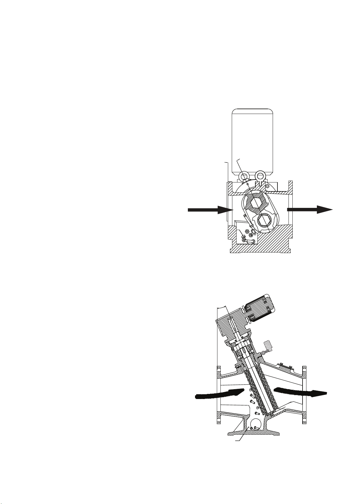
The unique internal trash trap built into the main body of
the machine (patent pending), has access covers placed
on either side for easy clean out.
Access cover plates drilled to suit standard NP16 50mm
diameter flange to allow hosetail or similar to be fitted for
flushing exercise when required.
25°
9) Shafts should be clean and any burrs fi led off for
easier stacking. Inspect shafts for excessive wear of
hexagonal portion. Replace if necessary.
3.4 REASSEMBLY ADVICE
1) Lubricate all bores, shafts and seals on reassembly.
2) Lubricate gears on re-assembly with the specifi ed
lubricant.
3) Reconnect wiring at motor(s) terminal box(es) using
tag leads for identifi cation.
4) Re-open system isolation valves.
5) On completion of assembly, run through the ‘initial
start-up’ procedure on page 11.
TR MUNCHERS ONLY
25° CUTTER STACK AND TRASH TRAP (CT201,CT206
& CT205 ONLY)
The cutter stack is inclined at 25° from the vertical
axis to allow any unbreakable solids to drop clear of
the cutters into the trash trap on reversal side of the
cutter stacks. the solids can then be manually removed
once the machine has been isolated (mechanically and
electrically).
CT201
25°
TRASH
TRAP
CT203 & CT205
13
Page 14
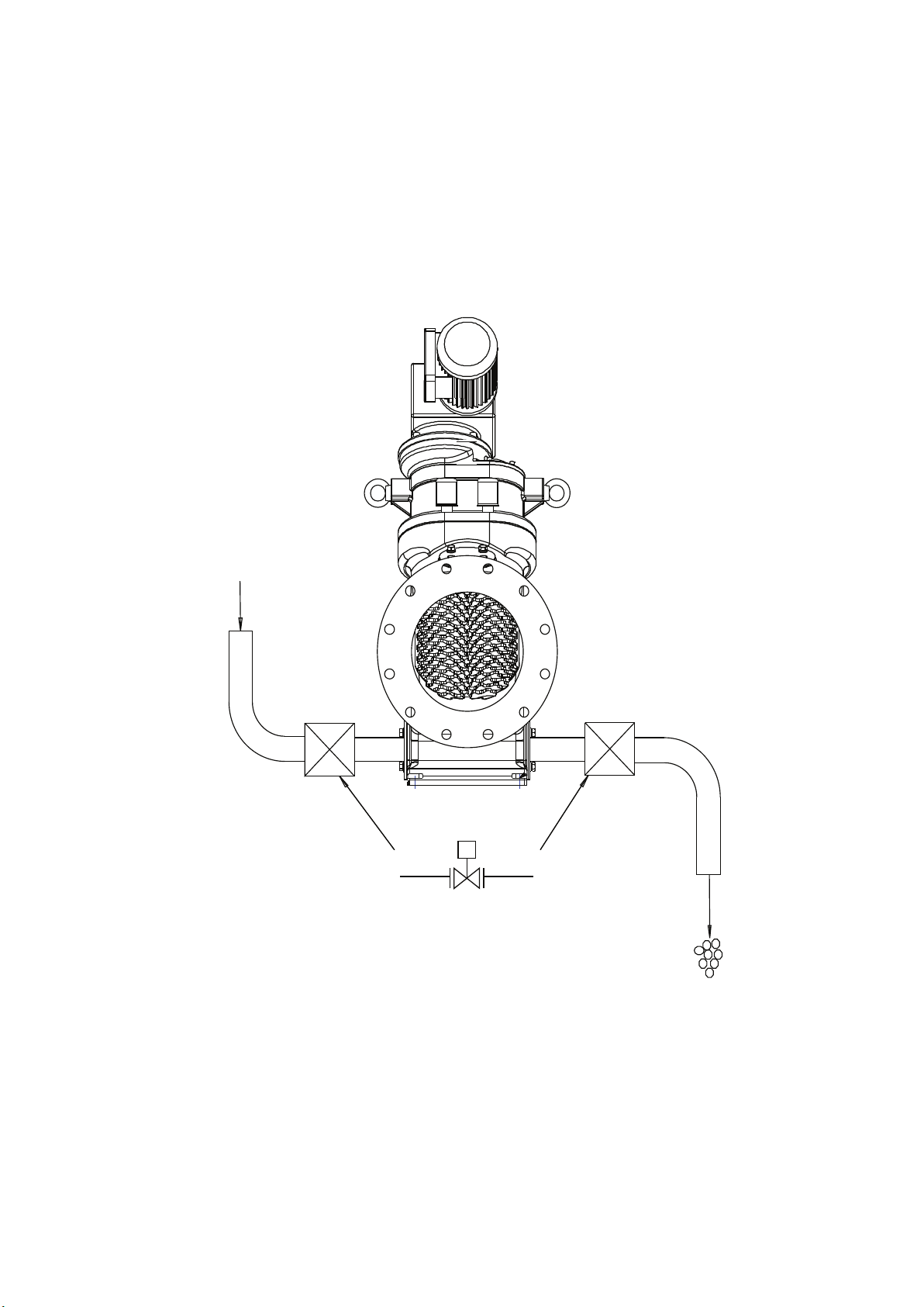
CLEAN OUT FACILITY (TR MUNCHER ONLY)
Using the two clean out access ports, fl anged hoses
and valves can be fi tted to give an automatic fl ushing
sequence at sites where grit/solids are known to cause
problems.
H2O
S
14
Page 15
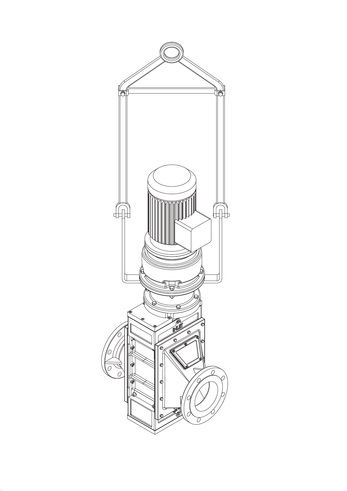
Recommended Lifting
15
Page 16
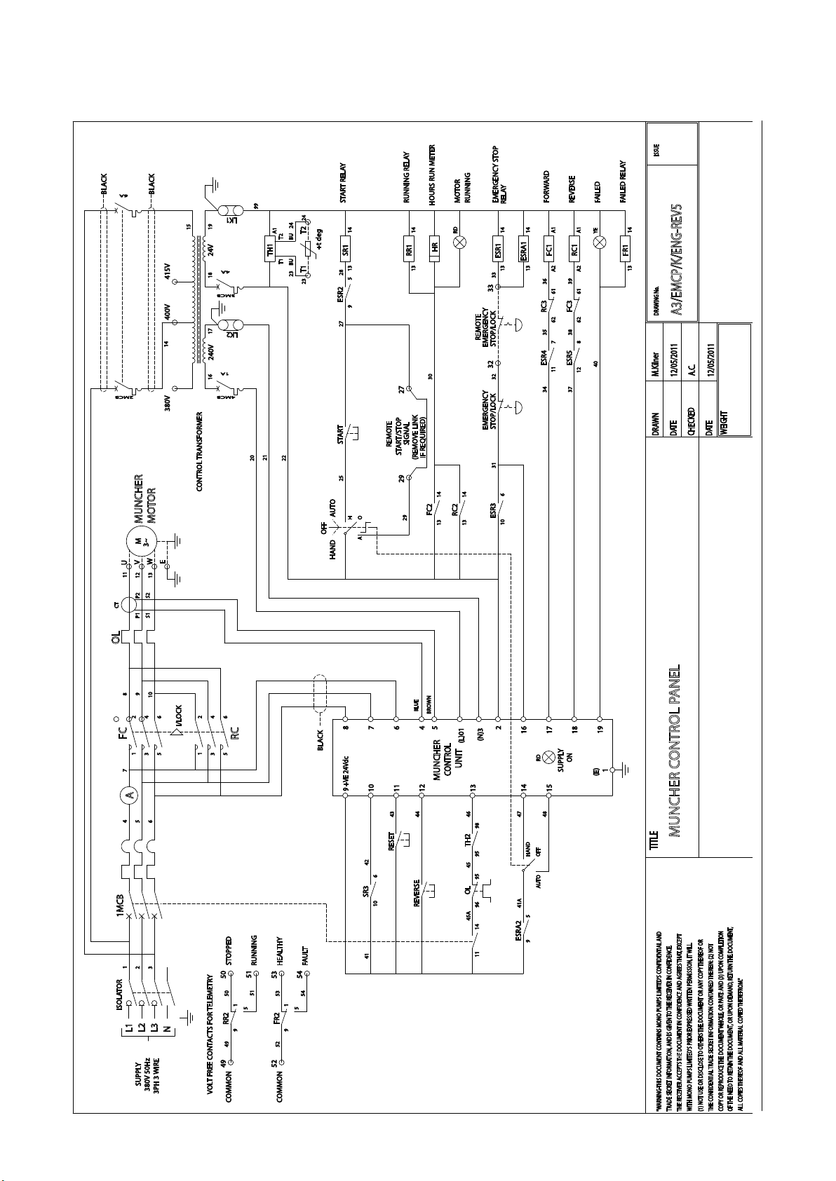
Wiring Diagram
16
Page 17

Weights
Muncher Type
CA202AA
CA203AA
CA205AA
CA206AA
CA210AA
CA215AA
CA202AB
CA203AB
Series A
Series F
CA205AB
CA206AB
CA210AB
CA215AB
CA202AC
CA203AC
CA205AC
CA206AC
CA210AC
CA215AC
CF306RJS7B2
CF310RMS7B2
Gear Unit /
Class
IP55 2
IP55 2
IP55 4
Nord IP55
M/C Size (kW)
11
7.5 & 11
Weight
(kg)
241
251
276
286
351
400
254
264
284
294
369
439
265
275
295
305
380
450
780
1180
Series H
SB
TR
CH06
CH09
CH12
Pipeline CB201
Channel CB201A
CT203C IP55
CT203D IP55
CT203E IP55
Nord IP55
IP55
IP55
IP55
IP67 & IP68
11 & 15
15 & 22
1.1
1.5
2.2
1.1
1.5
2.2
1.1
1.5
2.2
1.1
1.5
2.2
1.5
2.2 / 4.0
1.5
2.2 / 4.0
1.5
2.2 / 4.0
1800
2300
2800
205
207
244
208
244
248
155
190
195
200
225
260
290
340
290
340
290
340
CT205F IP55
CT205G IP55
R CR145A IP55 8 800
1.5
2.2 / 4.0
1.5
2.2 / 4.0
345
390
345
390
17
Page 18

Muncher Type Gear Unit / Class M/C Size (HP) Weight (lb)
Series A
Series F
Series H
CA202AA
CA203AA
CA205AA
CA206AA
CA210AA
CA215AA
CA202AB
CA203AB
CA205AB
CA206AB
CA210AB
CA215AB
CA202AC
CA203AC
CA205AC
CA206AC
CA210AC
CA215AC
CF306RJS7B2
CF310RMS7B2
CH06
CH09
CH12
TEFC 2
TEFC 3
TEFC 5
TEFC
TEFC
10 & 15
15 & 20 /
20 & 30
15
531
553
608
630
773
881
559
582
626
648
813
967
584
606
650
672
837
992
1719
2601
3968
5070
6172
SB
TR
Pipeline CB201
SUBMERSIBLE
Channel CB201A
SUBMERSIBLE
CT203P TEFC
CT203Q TEFC
CT203R TEFC
CT203S TEFC
CT203T TEFC
TEFC
TEFC
1.5
2
3
1.5
2
3
1.5
2
3
1.5
2
3
2
3 / 5
15
10 & 15
15
10 & 15
15
10 & 15
15
10 & 15
451
456
537
458
537
546
341
418
429
440
496
573
639
749
639
749
639
749
760
859
760
859
R CR145A TEFC 10 1763
18
Page 19
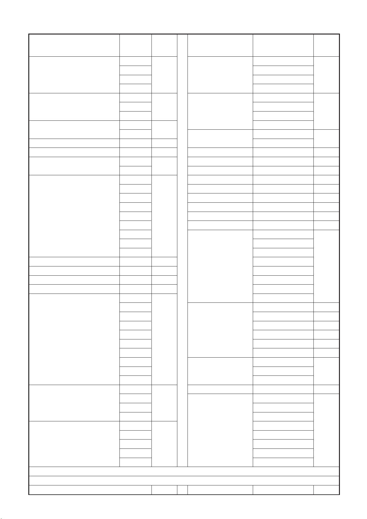
Part Numbers
DESCRIPTION
Bearing Housing
Mid Housing
Nameplate
Warning Nameplate 0650 06B 3504
Bottom Cover Plate 1100 11A Spacer (Mid Bearing) 3556² 35C
Top Cover Plate
Adapter Stool
Cover Plate Gasket 2000 20A 2695¹
Side Rail Gasket 2010 20B 2696¹
Mid Bearing Housing Gasket 2020 20C 2697¹
Mounting Flange Gasket 2021 20D 2698¹
Side Rail
Cutter
Drive Shaft
¹ - Machines prior to 21/09/2015
² - Machines after 21/09/2015
For more information contact your Supplier
NOV
PART NO.
0100
0101 3255
0112 3256²
0113 3500
0175
0176 3502
0177 3506
0600
0630
1150
1152 Retaining Washer 4702 47A
1701
1708 Drive Gear 7800 78A
1720 Driven Gear 7850 78B
1721 Lifting Lug 9700 97A
1722
1723 Coupling Variations
1724
1725 2691¹
1726 2692¹
2100
2101
2105 2601 26B
2106
2110
2111
2120
2121
2123 80B06893²
2511
2513
2515 M040127G-T¹
2516 M040127G-NORTH¹
3200¹
3201 M040227G²
3205 M040227G-T²
3206² M040227G-NORTH²
3251 M040229G²
DRG.
REF
01A Driven Shaft
01B
06A
11B
17A
21A
25A
32A
DESCRIPTION NOV PART NO.
Spacer
Shim Spacer
Sleeve (Mid Bearing) 3557² 35D
Lock Washer 4701 47B
1 Piece Coupling
2 Piece Coupling
Pin & Buffer Coupling
Seal Variations
Mechanical Seal
DRG.
REF
3250¹
32B
3501
35A
3551
3503
2690¹
2699¹
2600 26A
80B06891²
M040127G¹
M040129G¹
35B
26C
P2092122 80B06892²
P305
19
Page 20
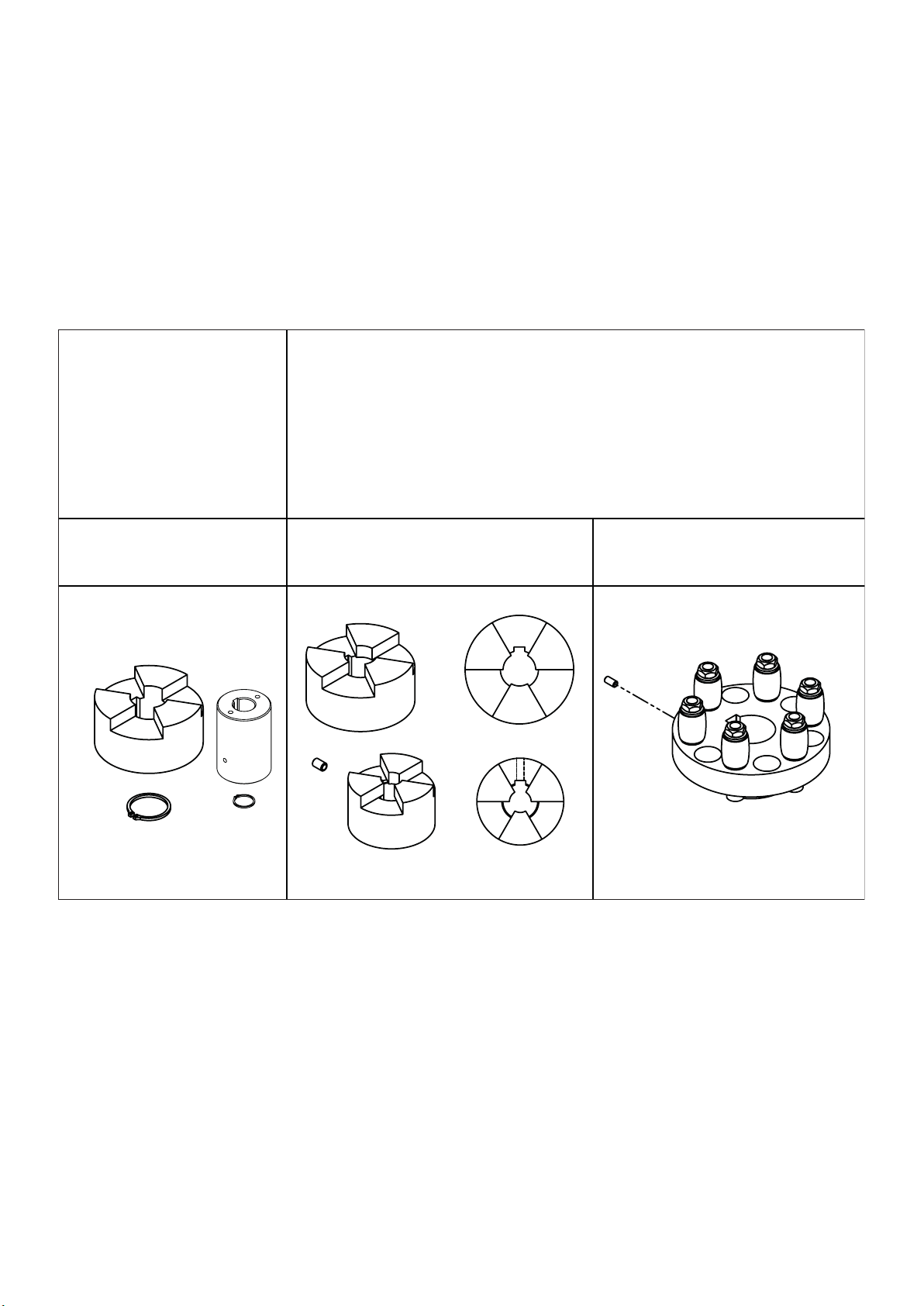
Coupling Options
BEFORE
BEFORE
24/09/2015
24/09/2015
Serial Number 801481
CA202 - CA215 CA202 - CA206 CA210 - CA215
CA202 - CA215 CA202 - CA206 CA210 - CA215
AFTER
AFTER
24/09/2015
24/09/2015
20
Page 21

Torque Settings
DESCRIPTION
THREAD
SIZE
PART NO.
MAX. TIGHTENING
TORQUE
Nm
Lbf.ft.
SLOTTED HEX NUT M24 x 3 P106 230
SOCKET CAP SCREW M10 x 1.5 P107 56
SOCKET CAP SCREW M8 x 1.25 P108 29
HEX HEAD SCREW M8 x 1.25 P109 29
SOCKET CAP SCREW M10 x 1.5 P114 56
HEX HEAD BOLT M12 x 1.75 P201 101
HEX HEAD BOLT M12 x 1.75 P202 101
HEX HEAD SCREW M10 x 1.5 P207 56
HEX HEAD SCREW M8 x 1.25 P400 29
HEX HEAD BOLT M8 x 1.25 P401 29
170
41
22
22
41
76
76
41
22
22
Torque tolerances are +/- 5% of stated values.
21
Page 22

Muncher Coding Sheet
Features Description
Body Material
Product Series A Muncher A
Mark No. 2014 2
Throat Size
Machine Type and
Flange Bore
(Metric Flanges Drilled to BS4504
PN16 and Imperial Flanges
Drilled to ANSI B16.5 Class 150)
Build Option Refer to NOV *
Cutter
No. of Teeth
Thickness
Material (Cutters)
Oblique /
Field Variation V A R
Typical Code C A 3 0 2 B * T 7 B 2 / 1 2 3
Basic Code Variation
1 2 3 4 5 6 7 8 9 10 11 12 13 14 15
Cast Iron C
Stainless Steel ** S
Gun Metal ** G
200mm (8”) 0 2
300mm (12”) 0 3
500mm (20”) 0 5
600mm (24”) 0 6
1000mm (40”) 1 0
1500mm (60”) 1 5
Basic (Channel Type) A
Pipeline 80 N.B. to BS4504 B
Pipeline 100 N.B. to BS4504 C
Pipeline 150 N.B. to BS4504 D
Pipeline 200 N.B. to BS4504 E
Pipeline 250 N.B. to BS4504 F
Pipeline 300 N.B. to BS4504 G
Upow 80 N.B. to BS4504 H
Upow 100 N.B. to BS4504 J
Upow 150 N.B. to BS4504 K
Upow 200 N.B. to BS4504 L
Pipeline 3” N.B. ANSI N
Pipeline 4” N.B. ANSI P
Pipeline 6” N.B. ANSI Q
Pipeline 8” N.B. ANSI R
Pipeline 10” N.B. ANSI S
Pipeline 12” N.B. ANSI T
Upow 3” N.B. ANSI U
Upow 4” N.B. ANSI V
Upow 6” N.B. ANSI W
Upow 8” N.B. ANSI Y
CAM T
ETOS W
5 (ETOS Only) 5
7 (CAM Or ETOS) 7
5.5mm (0.2165”) A
8.0mm (0.3150”) B
Stainless Steel (ETOS Only) 1
Chromium Molybdenum Steel
(CAM Only)
2
** Stainless Steel construction available with high ow side rails only
Note: “X” in any column denotes a special variation.
22
Page 23
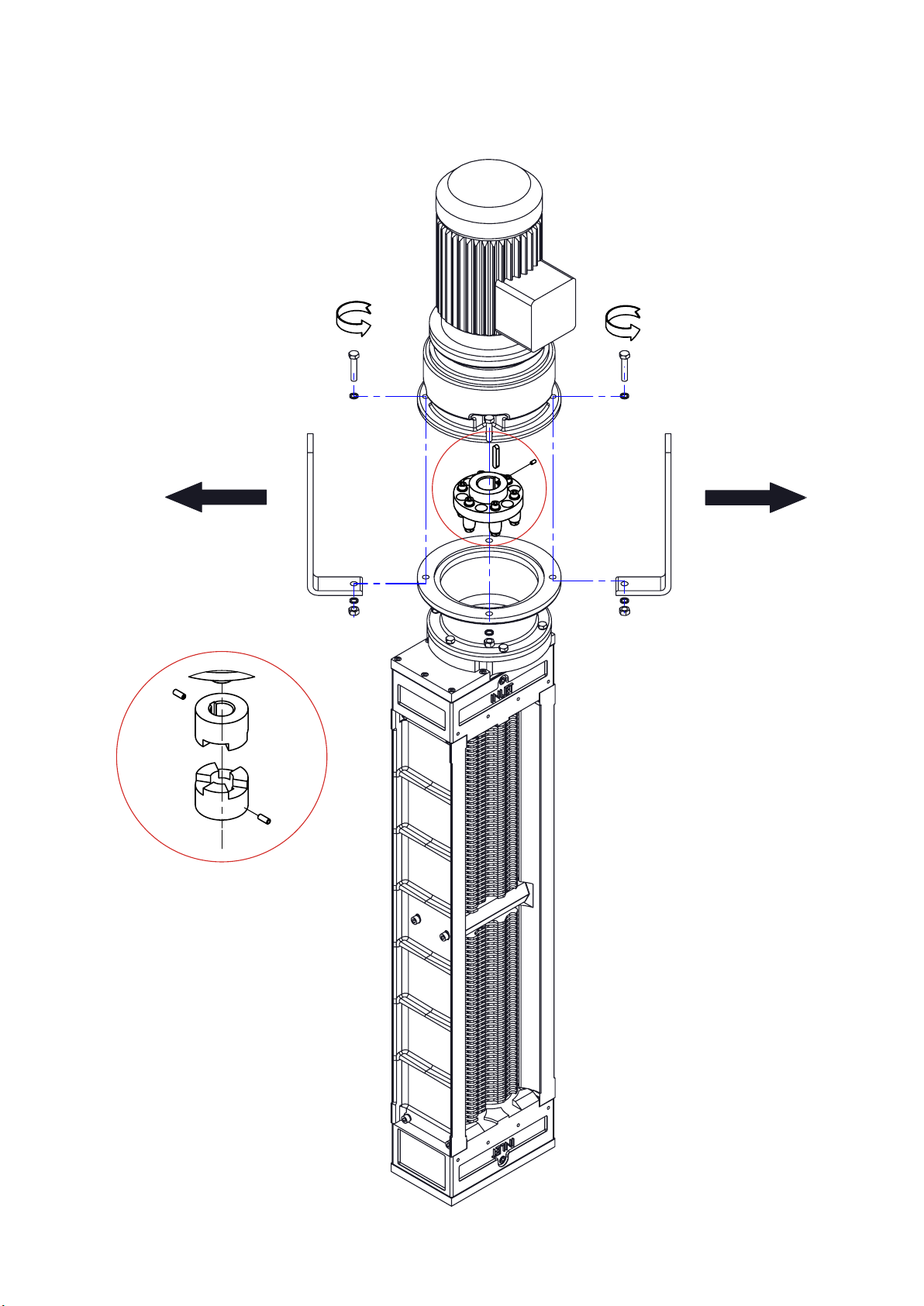
Dismantling Drawings
23
Page 24
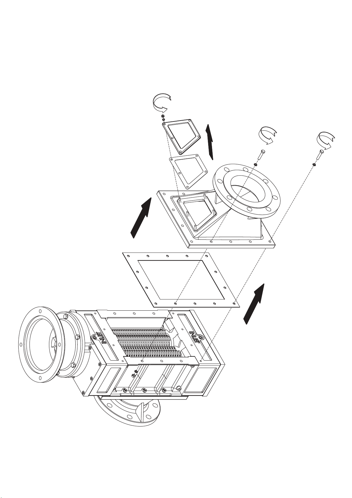
24 25 26 27 28 29 30 31 32 33 34 35
Page 25
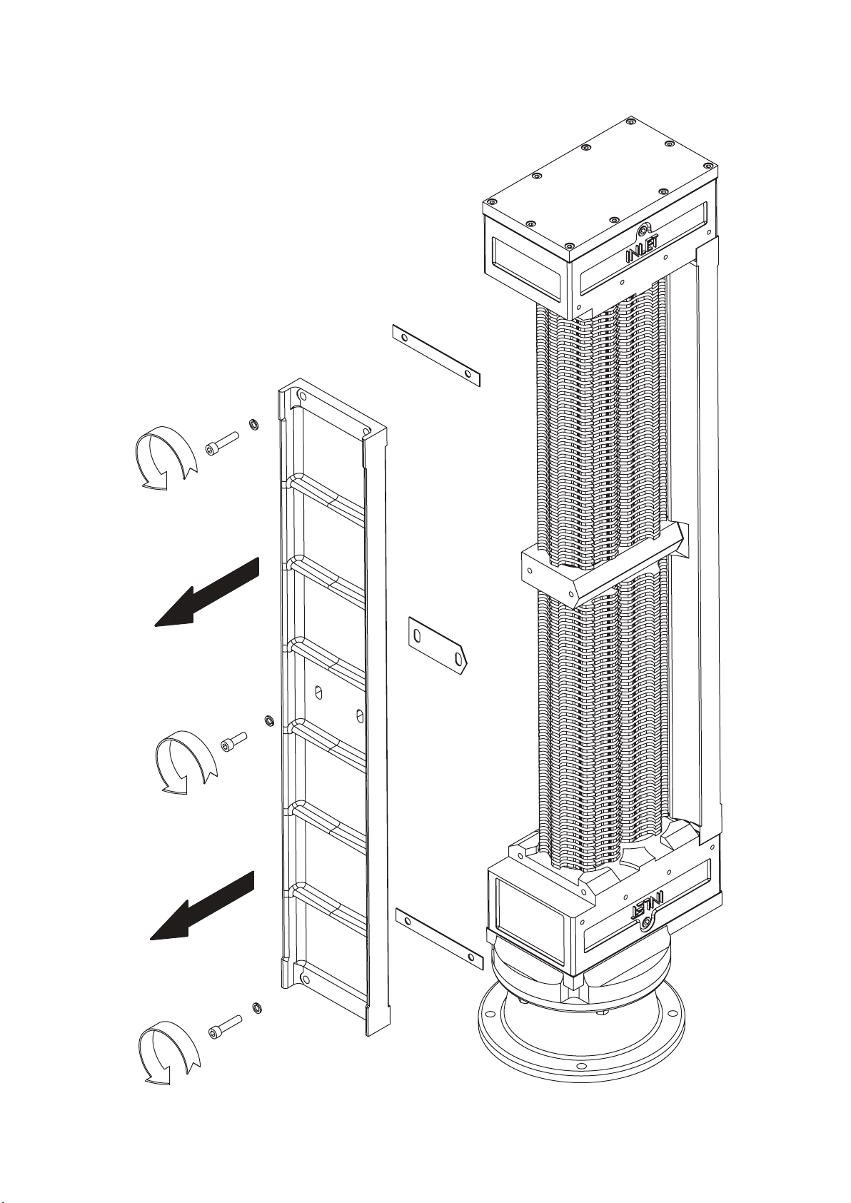
Page 26
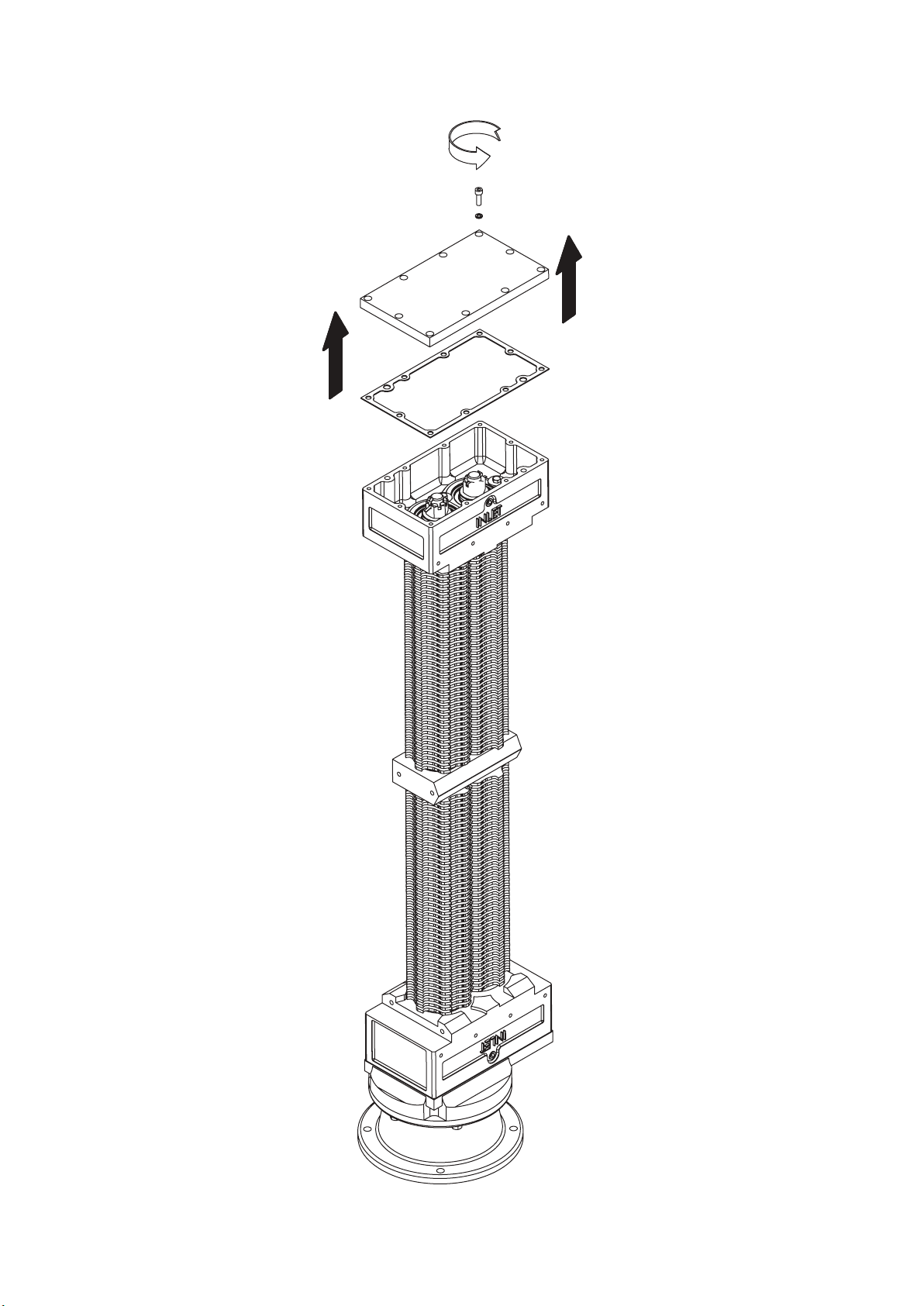
Page 27
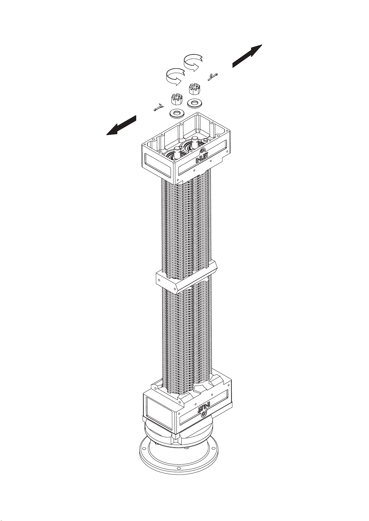
Page 28
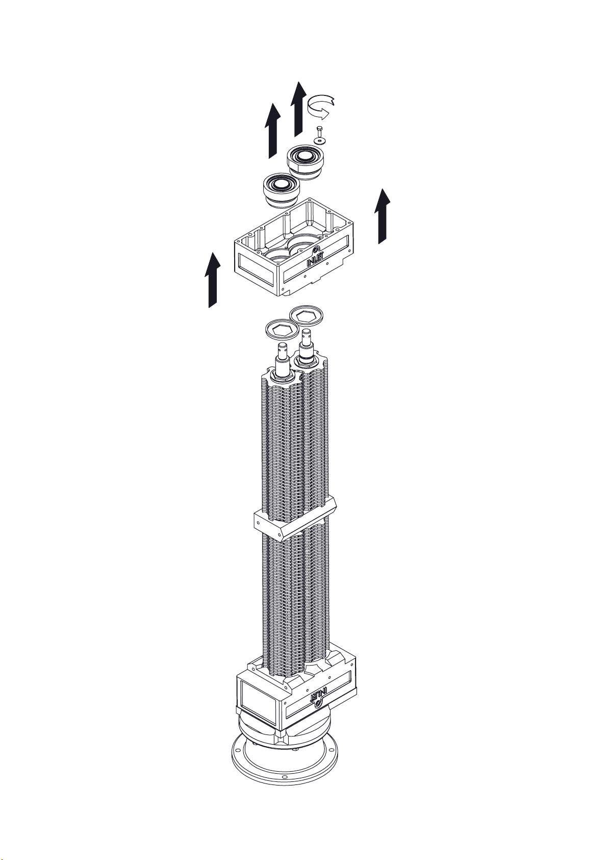
Page 29
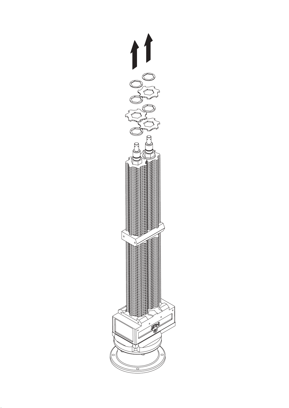
Page 30

Page 31
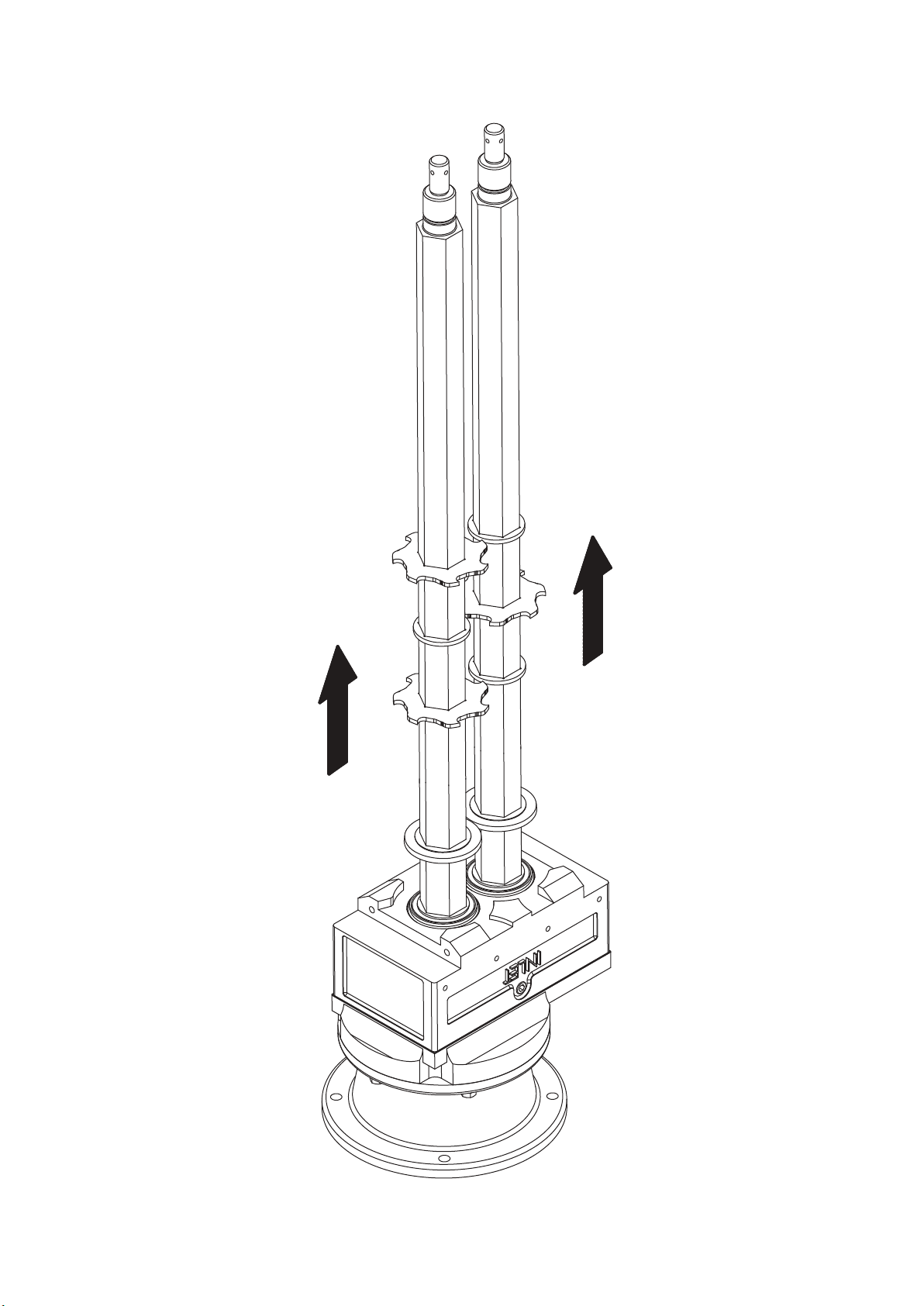
Page 32
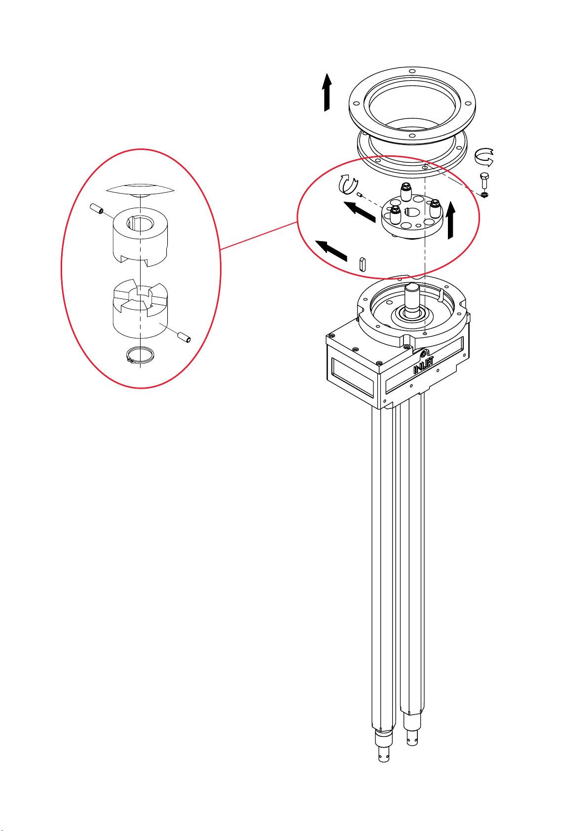
Page 33
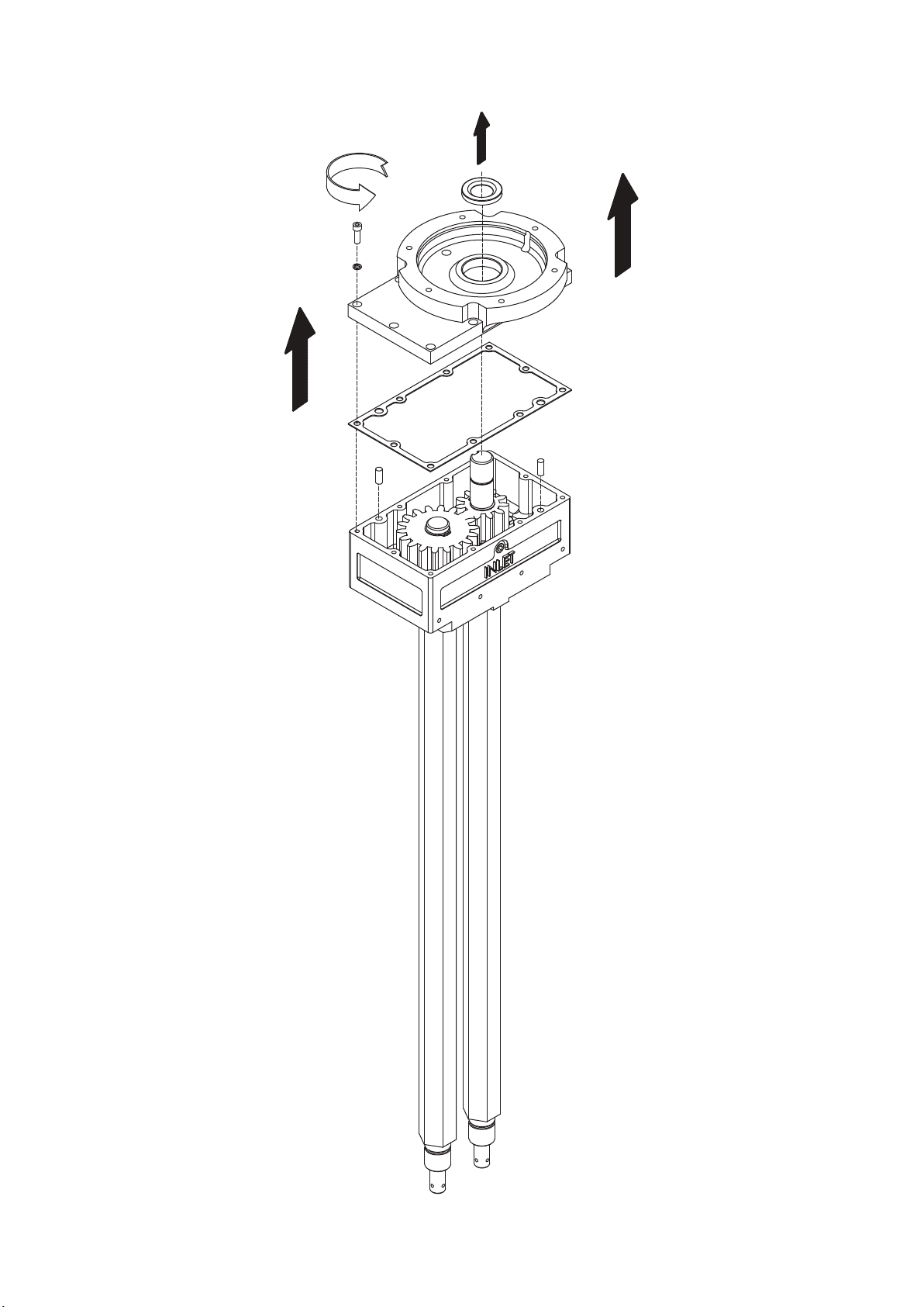
Page 34
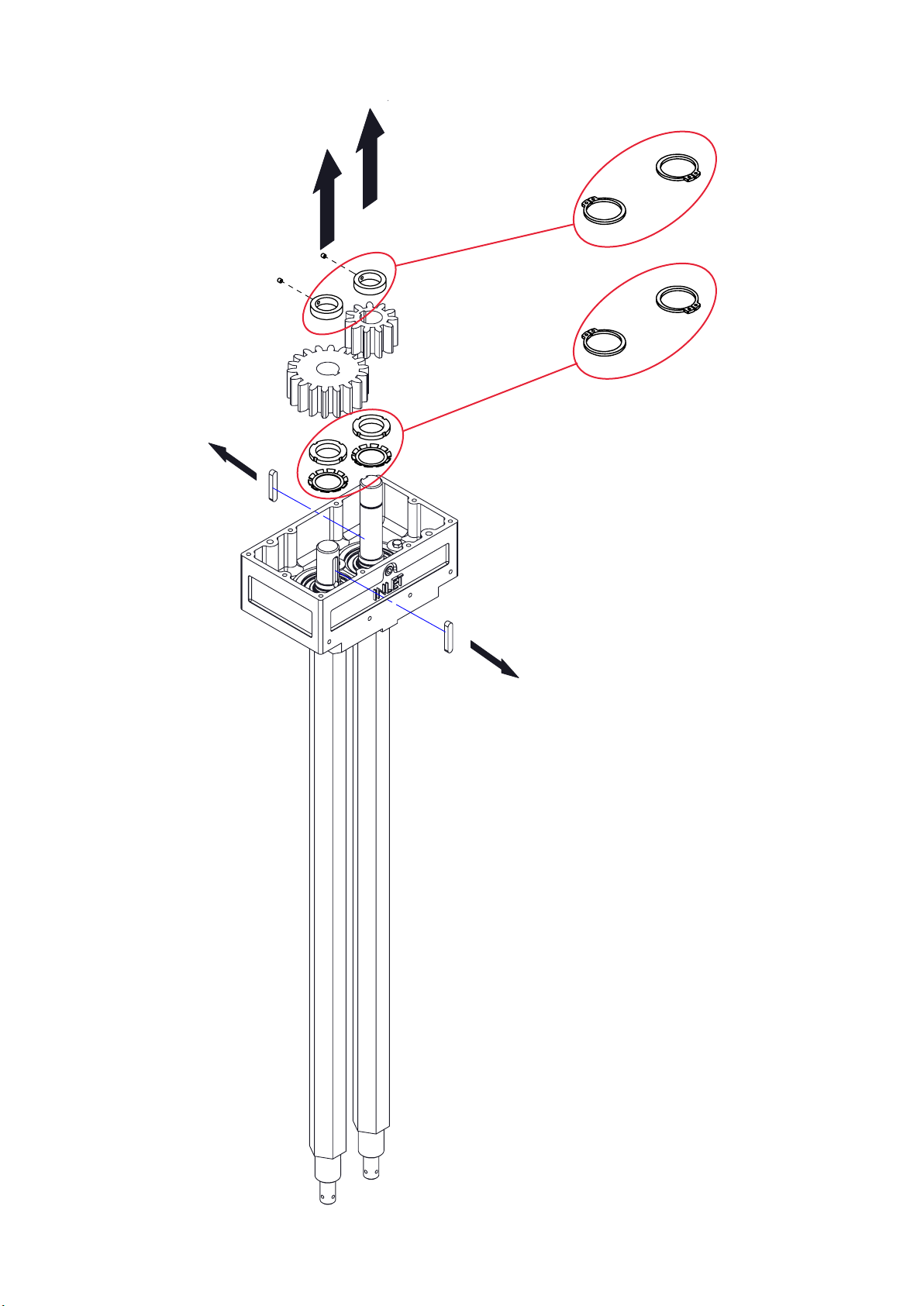
Page 35
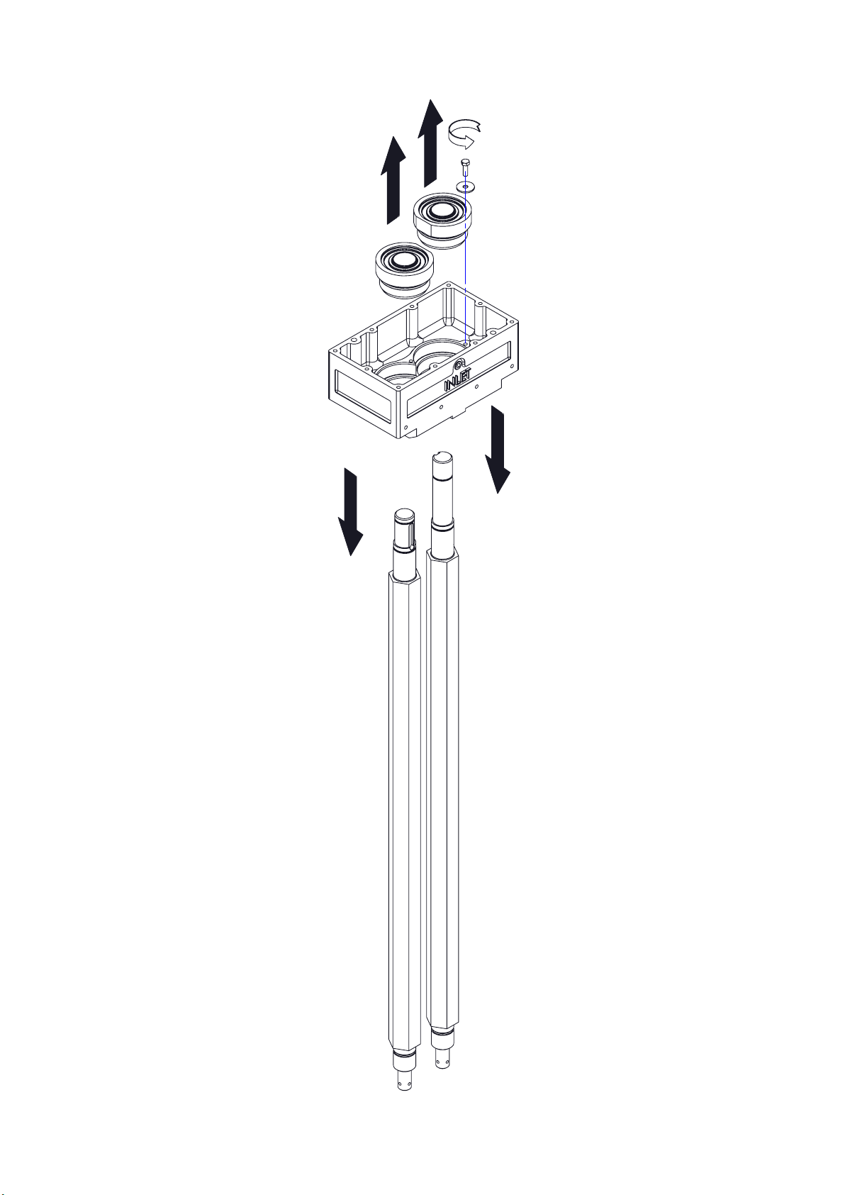
Page 36
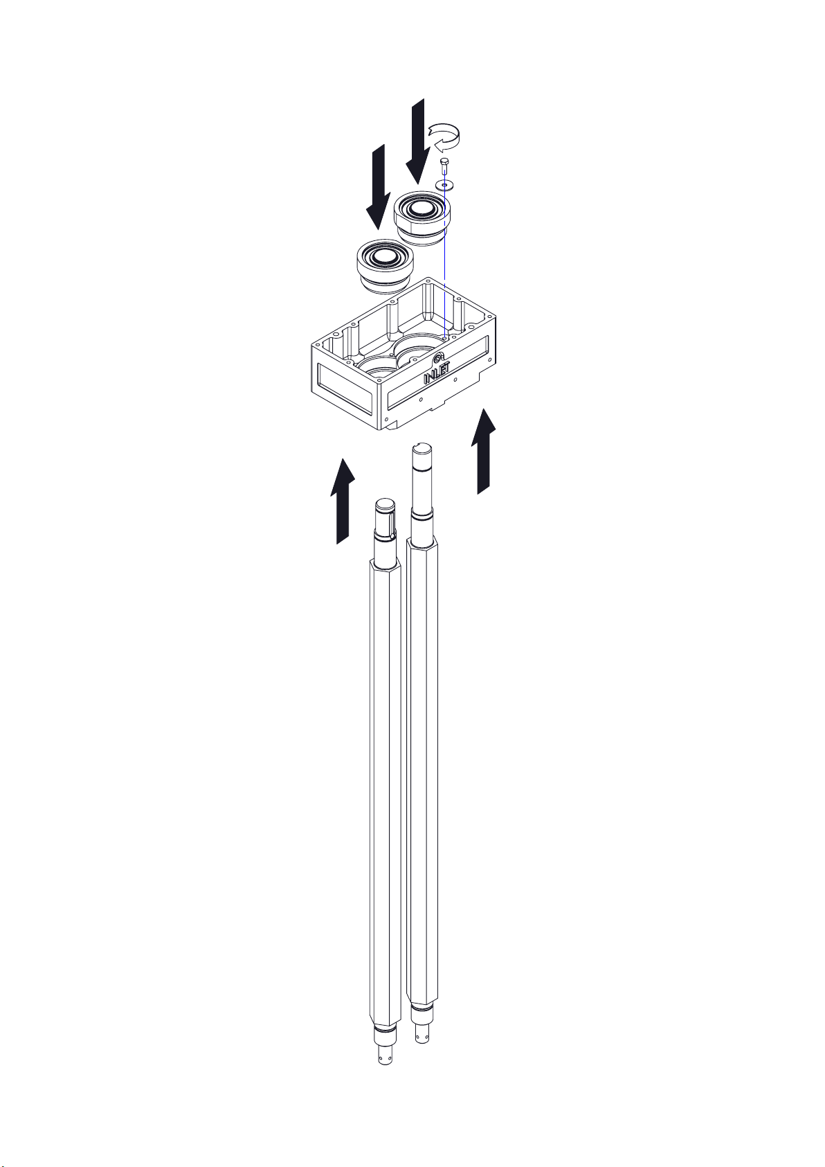
Assembly Drawings
36
Page 37
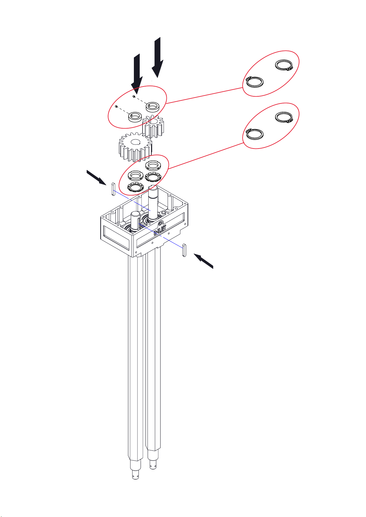
37 38 39 40 41 42 43 44 45 46 47
Page 38
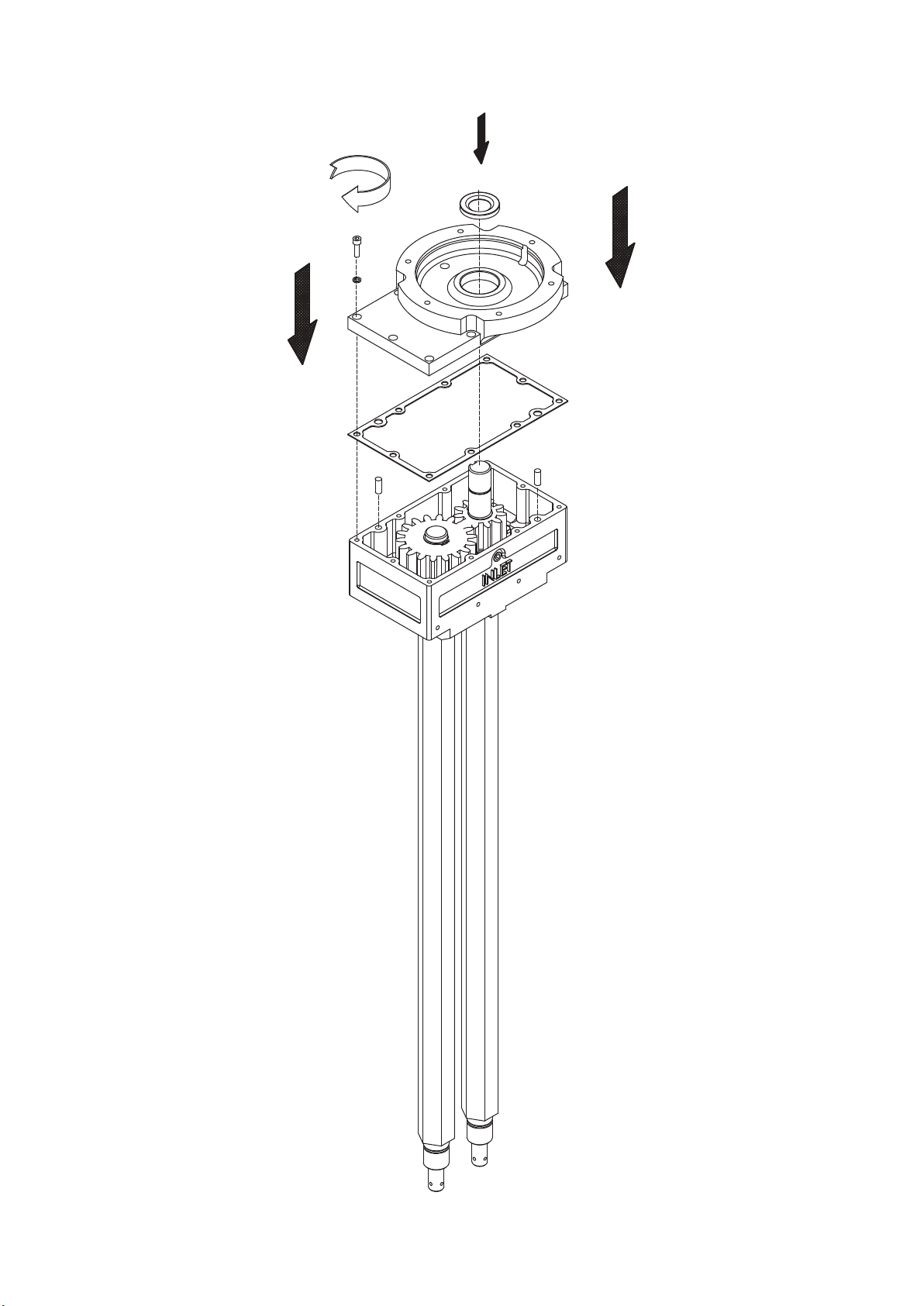
Page 39
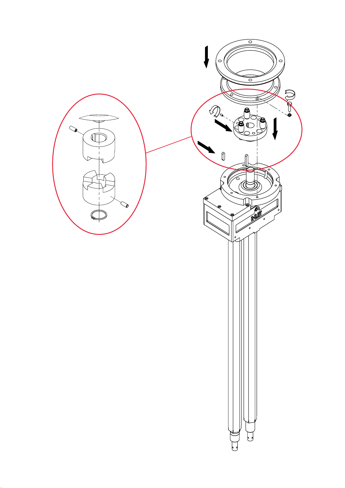
Page 40
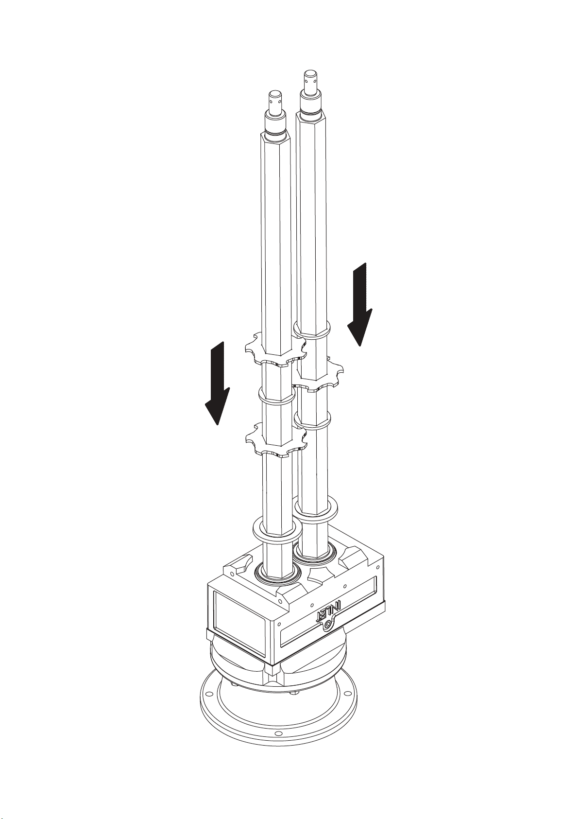
Page 41
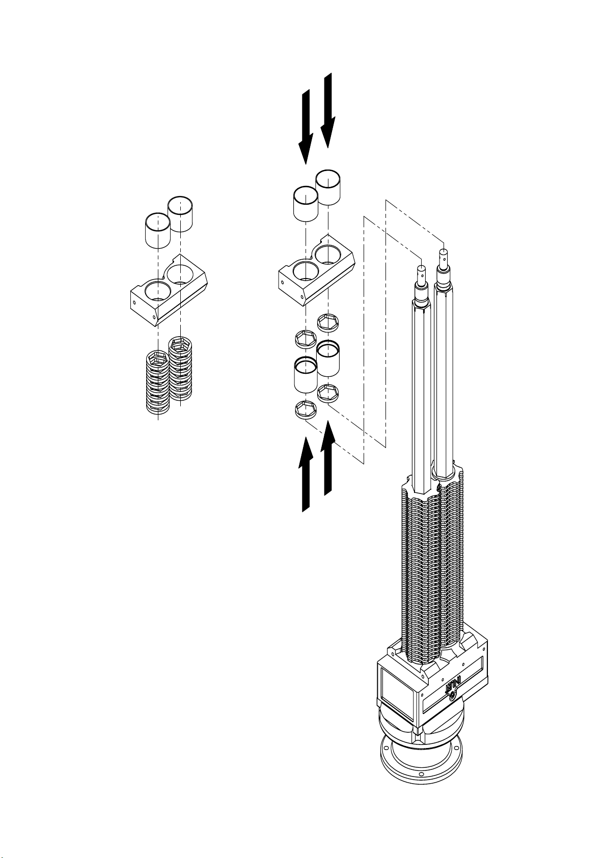
Page 42
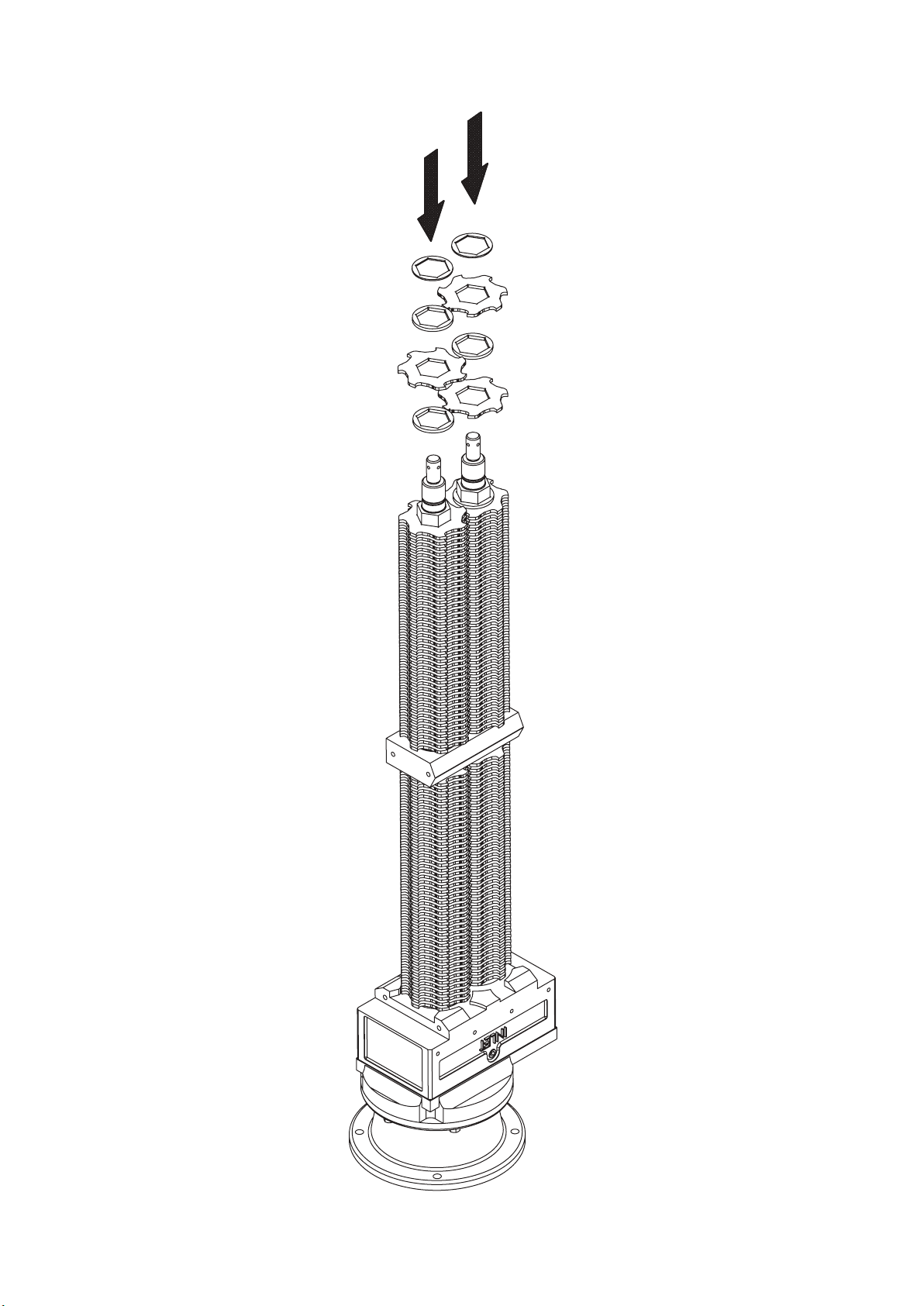
Page 43
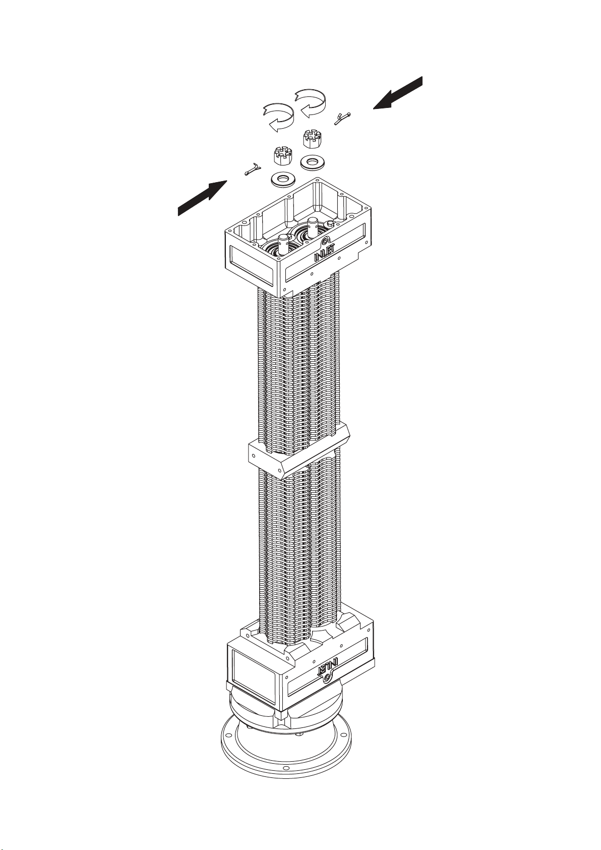
Page 44
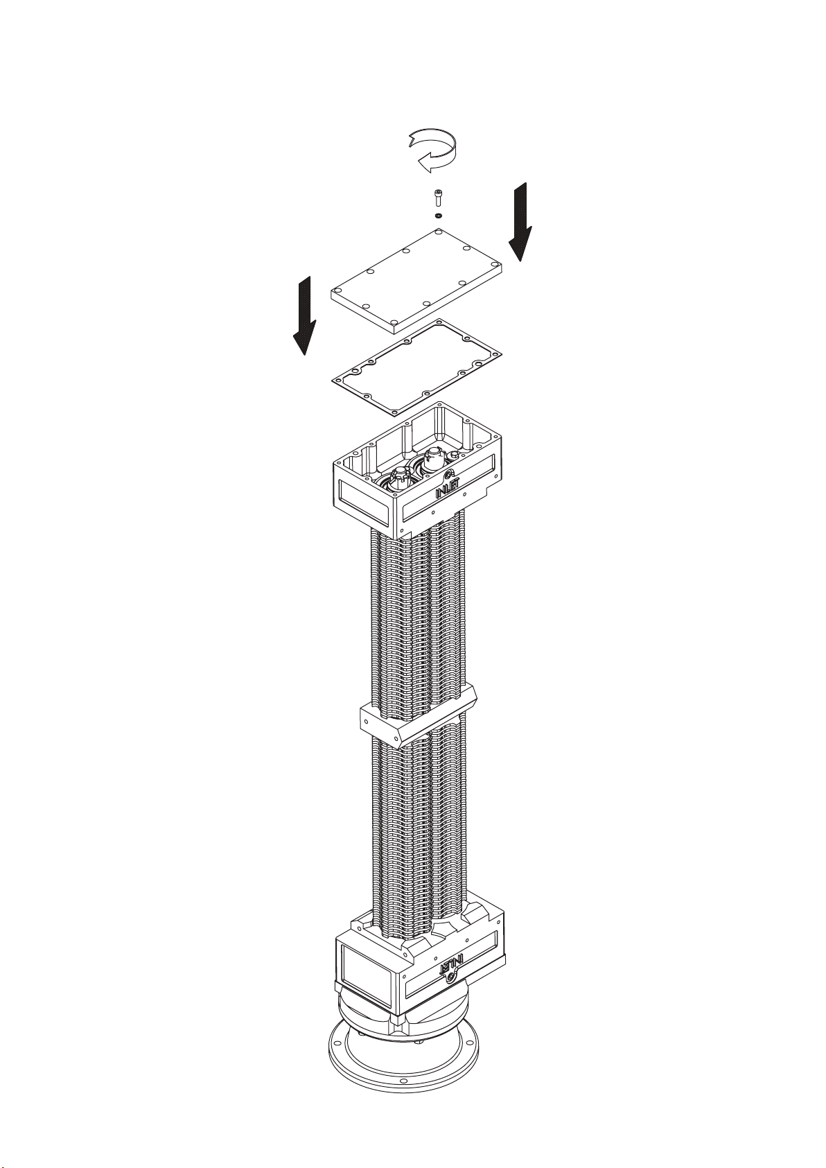
Page 45
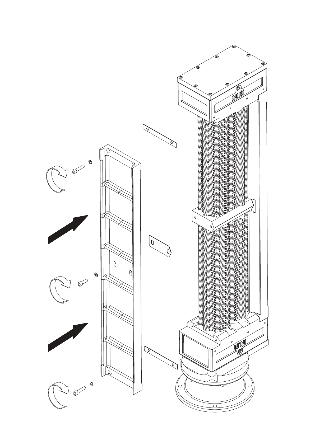
Page 46
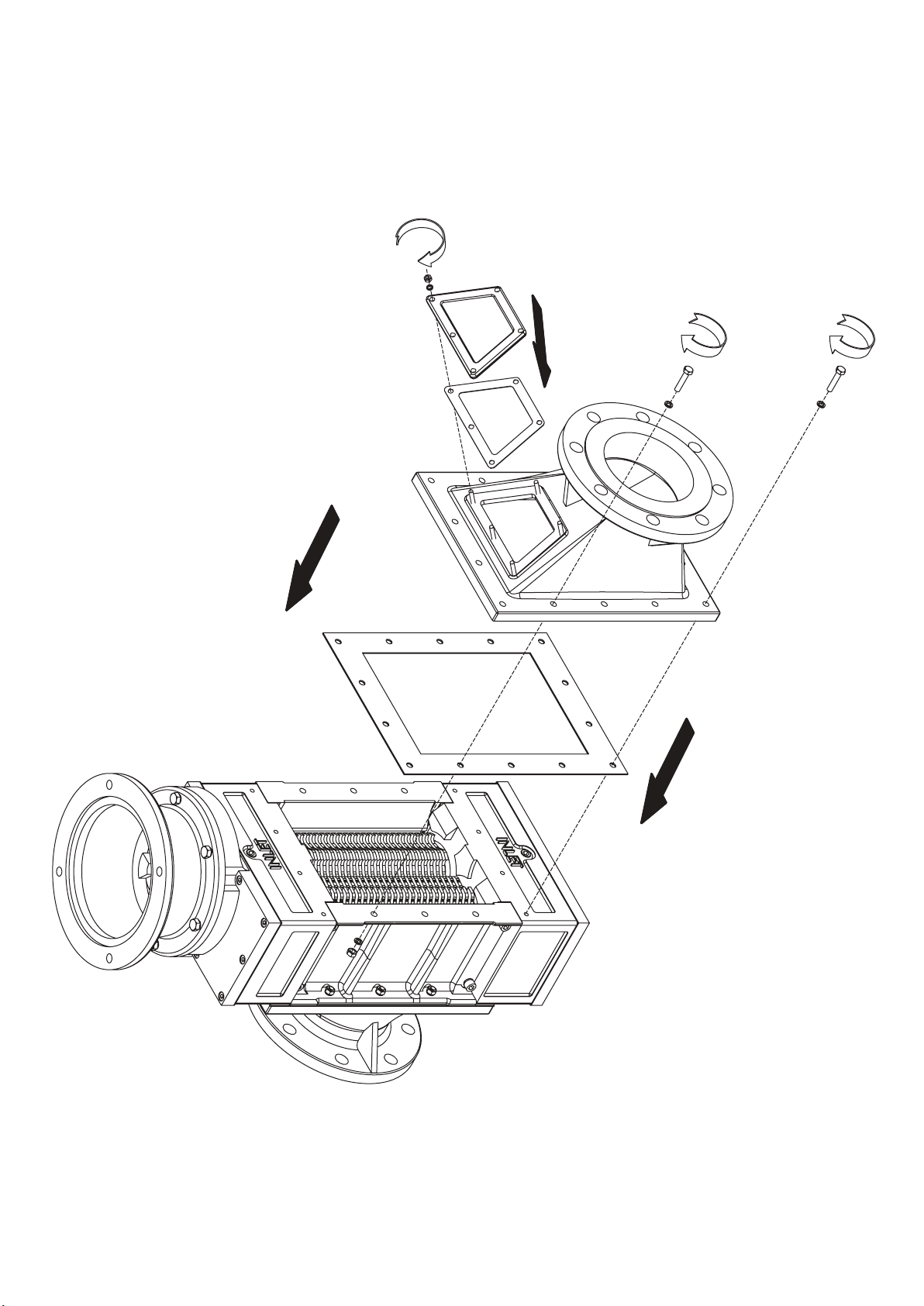
Page 47
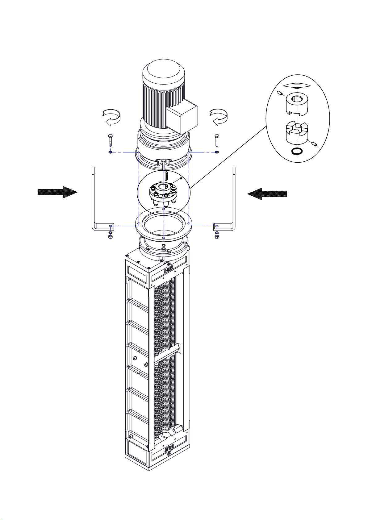
Page 48
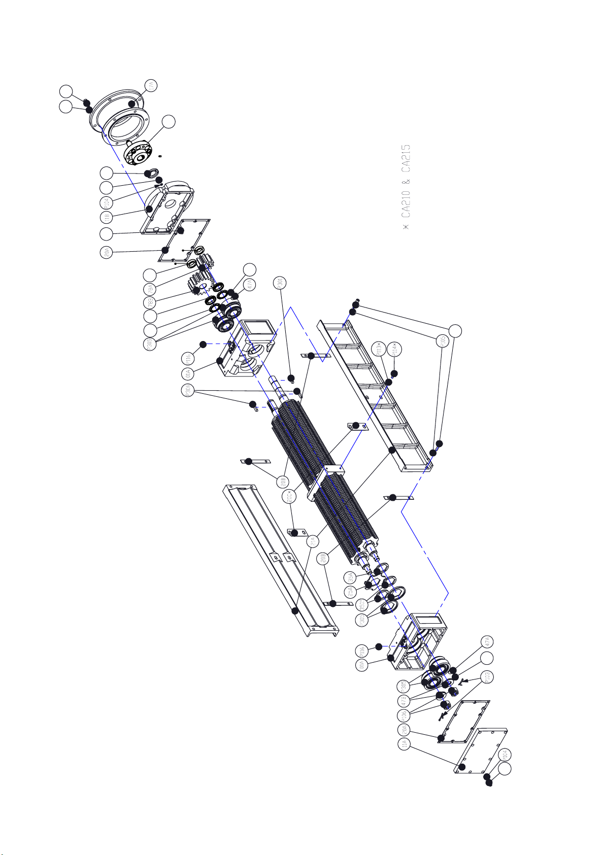
Exploded Views
P207
P208
P209
P102
P108
P101
P117
P119P118
P109
P107
48
P109
P108
Page 49
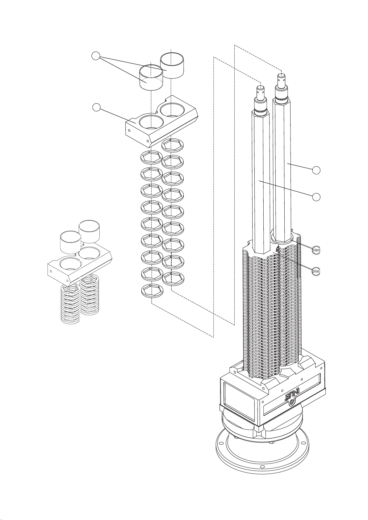
P30
3
5
3200
3250
017
49
Page 50
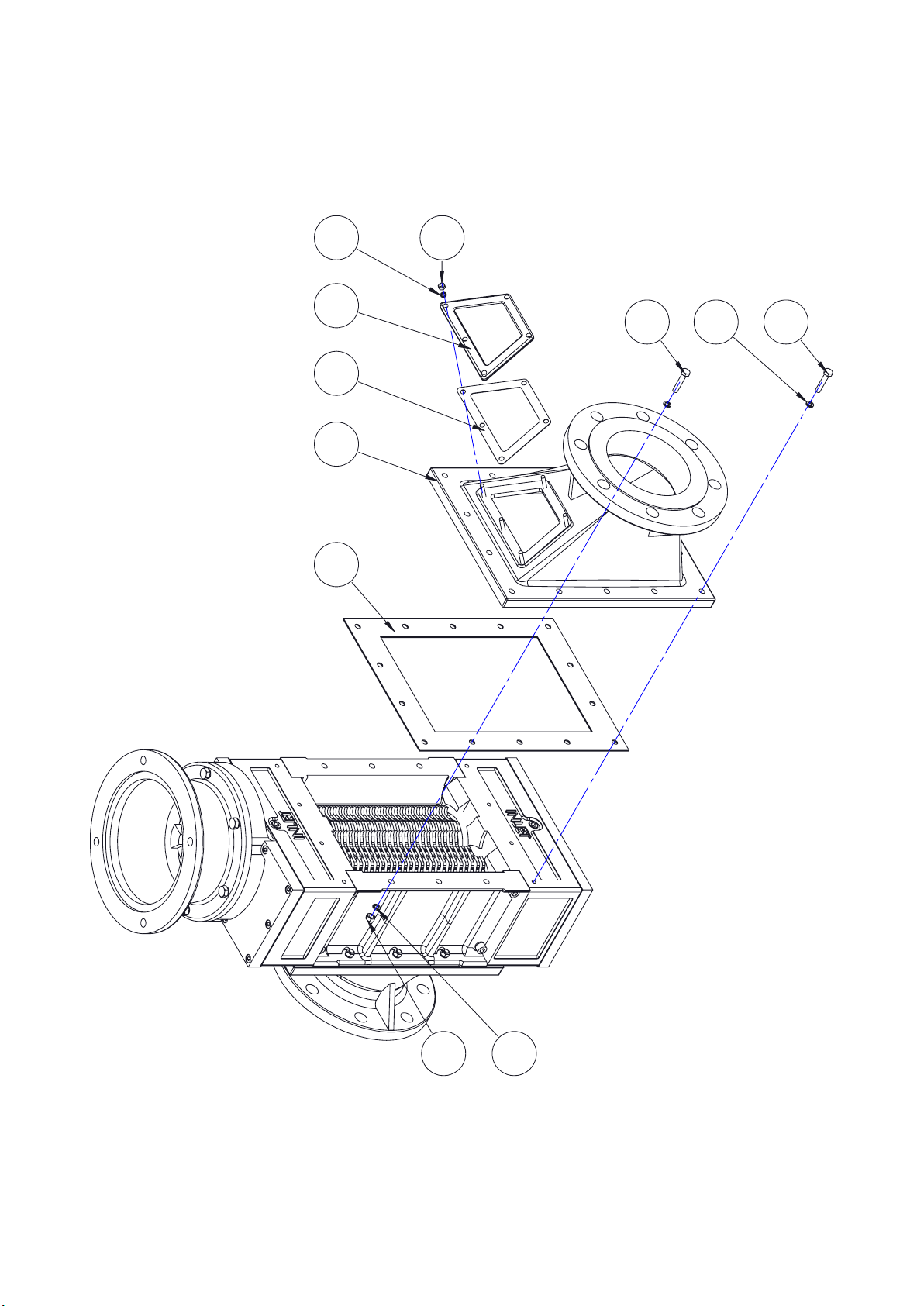
P405
P406
P402
59A
20E
24A
20D
P403
P401
P407
P400
50
Page 51
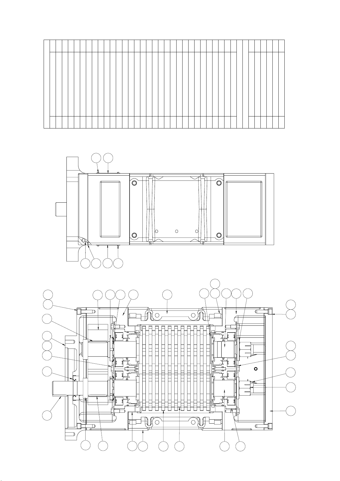
P117
P305
Sectional Arrrangement
2
QTY
BODY PARTS
DESCRIPTION
01A BEARING HOUSING
ITEM
1
1
4
1
1
2
4
8
NAMEPLATE (MUNCHER)
NAMEPLATE (WARNING)
MECHANICAL SEAL (INCL O-RINGS)
COVER PLATE (BOTTOM)
COVER PLATE (TOP)
COVER PLATE GASKET
SIDERAIL GASKET
WASHER
06A
06B
P305
11A
11B
20A
P115
20B
47A
06B
2
1
1
2
LOCK WASHER
DRIVE GEAR
DRIVEN GEAR
DOWEL PIN
47B
78B
78A
P101
1
2
8
2
20
ROTARY SHAFT LIPSEAL
SPLIT COTTER PIN
SGL COIL SPR WASHER
P102
P103
P104
8
ST STL SPR WASHER
ST STL HEX SOC CAPSCREW
P105
P106 SLOTTED HEX NUT
P107
8
4
4
8
2
2
20
ST STL HEX SOC CAPSCREW
HEX HD SCREW
ST STL SPR WASHER
ST STL HEX SOC CAPSCREW
DRIVESCREW
P108
P109
P113
P114
P115
2
HEX CSK PLUG
ABUTMENT RING
LOCK NUT
P116
P117
P118
2
1
2
LOCK WASHER
RECT PAR KEY
RECT PAR KEY
P119
P301
P306
*
2
1
1
ROTATING PARTS
SIDERAIL
CUTTER
DRIVE SHAFT
DRIVEN SHAFT
25A
32A
32B
21A
*
*
CUTTER SPACER
SHIM SPACER
35B
35A
P108 P104
P306
11B
P109
47A
P301 P102
P101
20A
78B
06A
P118
P115
P119
01A
21A
35B
P107 P105
32B
01A
47B
P108 P104
47A
P109
P103
P106
11A
78A
20B
21A
25A
51
35A
32A
Page 52
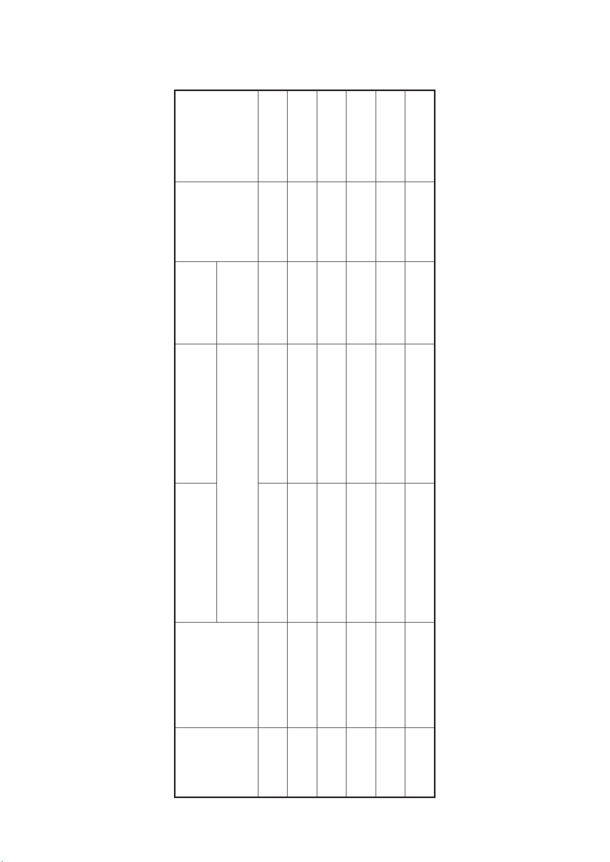
Adaptor Stool Coding
P.C.D.
FLANGE/
GEARBOX
SHAFT
GEARBOX
DIAMETER
SIZE
ONE PIECE
CA215
CA210,-
PART NO.
GEARBOX COUPLING
PART NO.
MUNCHER COUPLING
STOOL
ADAPTOR
SIZE CA202,CA203,CA205,CA206
PART NO.
ADAPTOR
CODE
STOOL
J CD A02A 1723 MS A02A 2601 MS A02B 2660 80B06893 45 250/215
H CD A02A 1724 MS A02A 2601 MS A02A 2655 80B06892 40 250/215
G CD A02A 1725 MS A02G 2626 MS A02G 2626 80B06891 35 250/215
52
L CD A02C 1701 MS A02A 2601 MS A02C 2627 48 260/230
K CD A02A 1701 MS A02A 2600 MS A02A 2627 38 210/180
M CD A02B 1701 MS A02A 2601 MS A02B 2627 58 340/310
Page 53
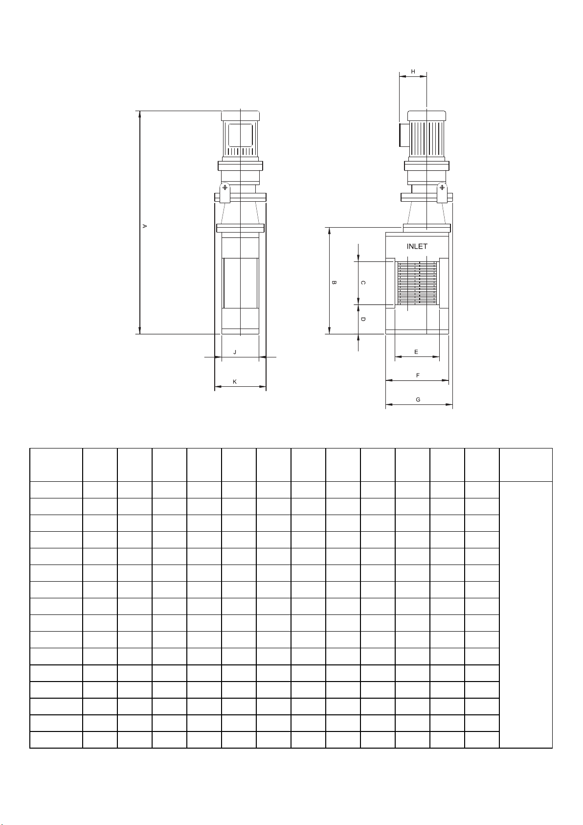
General Arrangements
MODEL kW
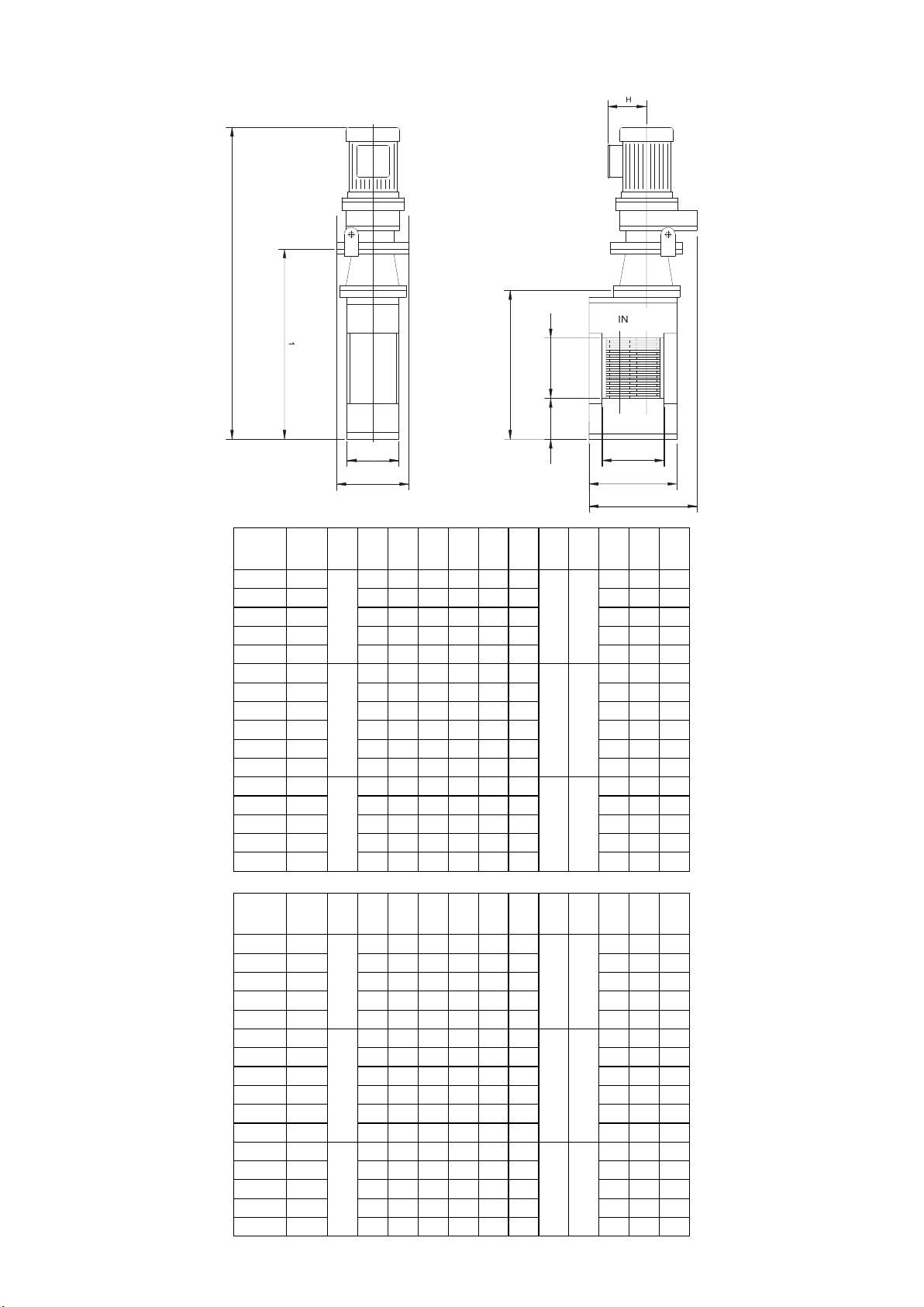
CA202AA 1.5 1059 515 175 155 215 305 350 145 178 260 159
CA203AA 1.5 1173 629 290 155 215 305 350 145 178 260 169
CA205AA 1.5 1323 779 440 155 215 305 350 145 178 260 189
CA206AA 1.5 1468 924 585 155 215 305 350 145 178 260 199
CA210AA 1.5 1883 1339 1000 155 215 305 350 145 178 260 274
CA202AB 2.2 1119 515 175 155 215 305 350 154 178 260 170
CA203AB 2.2 1233 629 290 155 215 305 350 154 178 260 180
CA205AB 2.2 1383 779 440 155 215 305 350 154 178 260 200
CA206AB 2.2 1528 924 585 155 215 305 350 154 178 260 210
CA210AB 2.2 1943 1339 1000 155 215 305 350 154 178 260 285
CA215AB 2.2 2453 1849 1510 155 215 305 350 154 178 260 355
CA202AC 4.0 1244 515 175 155 215 305 350 179 178 260 196
CA203AC 4.0 1358 629 290 155 215 305 350 179 178 260 206
CA205AC 4.0 1508 779 440 155 215 305 350 179 178 260 226
CA206AC 4.0 1653 924 585 155 215 305 350 179 178 260 236
CA210AC 4.0 2068 1339 1000 155 215 305 350 179 178 260 311
DIM A mmDIM B mmDIM C mmDIM D mmDIM E mmDIM F
mm
DIM G
(MAX)
mm
DIM H
mm
(MAX)
DIM J mmDIM K
mm
MASS
kg
(MAX)
CONDUIT
ENTRY
mm
21
53
Page 54
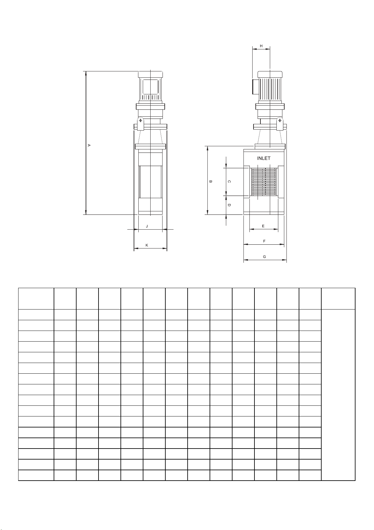
MODEL
CA202AA 2.0 41.7 20.3 6.9 6.1 8.5 12.0 13.8 5.7 7.0 10.2 351
CA203AA 2.0 46.2 24.8 11.4 6.1 8.5 12.0 13.8 5.7 7.0 10.2 373
CA205AA 2.0 52.1 30.7 17.3 6.1 8.5 12.0 13.8 5.7 7.0 10.2 417
CA206AA 2.0 57.8 36.4 23.0 6.1 8.5 12.0 13.8 5.7 7.0 10.2 439
CA210AA 2.0 74.1 52.7 39.4 6.1 8.5 12.0 13.8 5.7 7.0 10.2 605
CA202AB 3.0 44.1 20.3 6.9 6.1 8.5 12.0 13.8 6.1 7.0 10.2 375
CA203AB 3.0 48.5 24.8 11.4 6.1 8.5 12.0 13.8 6.1 7.0 10.2 397
MOTOR HPDIM A
inches
DIM B
inches
DIM C
inches
DIM D
inches
DIM E
inches
DIM F
inches
DIM G
inches
(MAX)
DIM H
inches
(MAX)
DIM J
inches
DIM K
inches
MASS
lb
(MAX)
CONDUIT
ENTRY
inches
CA205AB 3.0 54.4 30.7 17.3 6.1 8.5 12.0 13.8 6.1 7.0 10.2 441
CA206AB 3.0 60.2 36.4 23.0 6.1 8.5 12.0 13.8 6.1 7.0 10.2 463
CA210AB 3.0 76.5 52.7 39.4 6.1 8.5 12.0 13.8 6.1 7.0 10.2 629
CA215AB 3.0 96.6 72.8 59.4 6.1 8.5 12.0 13.8 6.1 7.0 10.2 783
CA202AC 5.4 49.0 20.3 6.9 6.1 8.5 12.0 13.8 7.0 7.0 10.2 432
CA203AC 5.4 53.5 24.8 11.4 6.1 8.5 12.0 13.8 7.0 7.0 10.2 455
CA205AC 5.4 59.4 30.7 17.3 6.1 8.5 12.0 13.8 7.0 7.0 10.2 499
CA206AC 5.4 65.1 36.4 23.0 6.1 8.5 12.0 13.8 7.0 7.0 10.2 521
CA210AC 5.4 81.4 52.7 39.4 6.1 8.5 12.0 13.8 7.0 7.0 10.2 686
54
0.8
Page 55
A
1
J
A
C
D
G
B
MOTOR kWDIM A
MODEL
CA202AA 1.5
CA203AA 1.5 748 629 290 155 215 305 178 260 131
CA205AA 1.5 898 779 440 155 215 305 178 260 151
CA206AA 1.5 1043 924 585 155 215 305 178 260 161
CA210AA 1.5 1458 1339 1000 155 215 305 178 260 236
CA202AB 2.2
CA203AB 2.2 757 629 290 155 215 305 178 260 131
CA205AB 2.2 907 779 440 155 215 305 178 260 151
CA206AB 2.2 1052 924 585 155 215 305 178 260 161
CA210AB 2.2 1467 1339 1000 155 215 305 178 260 236
CA215AB 2.2 1977 1849 1510 155 215 305 178 260 306
CA202AC 4.0
CA203AC 4.0 769 629 290 155 215 305 178 300 132
CA205AC 4.0 918 779 440 155 215 305 178 300 152
CA206AC 4.0 1063 924 585 155 215 305 178 300 162
CA210AC 4.0 1478 1339 1000 155 215 305 178 300 237
DIM
DIM B mmDIM C mmDIM D mmDIM E mmDIM F
A1
mm
mm
634 515 175 155 215 305
SEE DRIVE
UNIT SPEC
643 515 175 155 215 305
SEE DRIVE
UNIT SPEC
654 515 175 155 215 305
SEE DRIVE
UNIT SPEC
mm
DIM G
mm
(MAX)
SEE DRIVE
UNIT SPEC
SEE DRIVE
UNIT SPEC
SEE DRIVE
UNIT SPEC
DIM H
mm
(MAX)
SEE DRIVE
UNIT SPEC
SEE DRIVE
UNIT SPEC
SEE DRIVE
UNIT SPEC
mm
MASS
(MAX)
DIM J mmDIM K
178 260 121
178 260 121
178 300 122
kg
MOTOR HPDIM A
MODEL
CA202AA 2.0
CA203AA 2.0 29.4 24.8 11.4 6.1 8.5 12.0 7.0 10.2 289
CA205AA 2.0 35.4 30.7 17.3 6.1 8.5 12.0 7.0 10.2 333
CA206AA 2.0 41.1 36.4 23.0 6.1 8.5 12.0 7.0 10.2 355
CA210AA 2.0 57.4 52.7 39.4 6.1 8.5 12.0 7.0 10.2 521
CA202AB 3.0
CA203AB 3.0 29.8 24.8 11.4 6.1 8.5 12.0 7.0 10.2 289
CA205AB 3.0 35.7 30.7 17.3 6.1 8.5 12.0 7.0 10.2 333
CA206AB 3.0 41.4 36.4 23.0 6.1 8.5 12.0 7.0 10.2 355
CA210AB 3.0 57.8 52.7 39.4 6.1 8.5 12.0 7.0 10.2 521
CA215AB 3.0 77.8 72.8 59.4 6.1 8.5 12.0 7.0 10.2 675
CA202AC 5.4
CA203AC 5.4 30.3 24.8 11.4 6.1 8.5 12.0 7.0 11.8 291
CA205AC 5.4 36.1 30.7 17.3 6.1 8.5 12.0 7.0 11.8 335
CA206AC 5.4 41.9 36.4 23.0 6.1 8.5 12.0 7.0 11.8 357
CA210AC 5.4 58.2 52.7 39.4 6.1 8.5 12.0 7.0 11.8 523
DIM
DIM B
DIM C
A1
inches
UNIT SPEC
UNIT SPEC
UNIT SPEC
inches
inches
25.0 20.3 6.9 6.1 8.5 12.0
SEE DRIVE
25.3 20.3 6.9 6.1 8.5 12.0
SEE DRIVE
25.7 20.3 6.9 6.1 8.5 12.0
SEE DRIVE
inches
DIM D
inches
DIM E
inches
DIM F
inches
DIM G
inches
(MAX)
SEE DRIVE
UNIT SPEC
SEE DRIVE
UNIT SPEC
SEE DRIVE
UNIT SPEC
DIM H
inches
(MAX)
SEE DRIVE
UNIT SPEC
SEE DRIVE
UNIT SPEC
SEE DRIVE
UNIT SPEC
DIM J
DIM K
inches
inches
7.0 10.2 267
7.0 10.2 267
7.0 11.8 269
MASS
lb
(MAX)
55
Page 56
J
C
A
B
B.S.4504 PN16
K
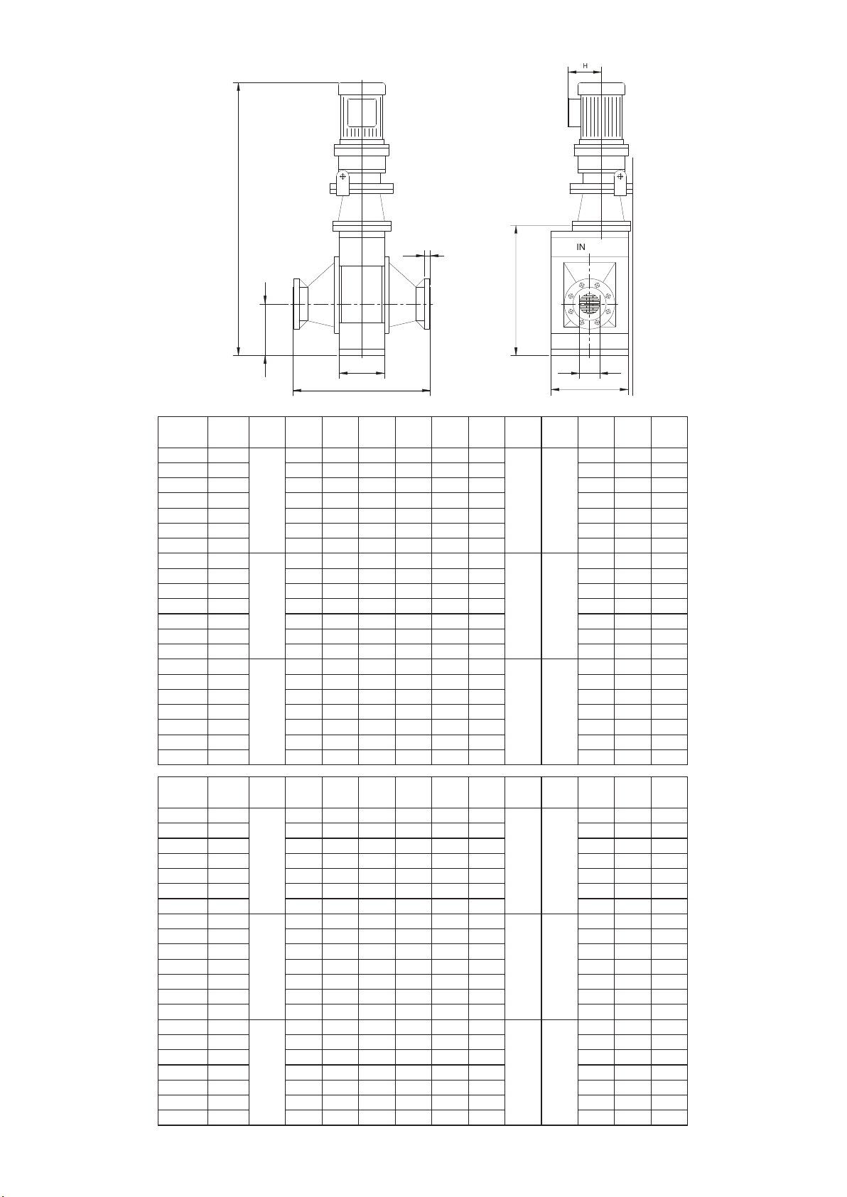
MODEL
CA202BA 2
CA202CA 2 634 515 205 24 100 305 178 544 150
CA202DA 2 634 515 205 24 150 305 178 544 152
CA203DA 2 748 629 230 24 150 305 178 544 167
CA203EA 2 748 629 255 24 200 305 178 584 179
CA205FA 2 898 779 280 24 250 305 178 684 224
CA206GA 2 1043 924 305 24 300 305 178 784 268
CA202BB 2
CA202CB 2 643 515 205 24 100 305 178 544 150
CA202DB 2 643 515 205 24 150 305 178 544 152
CA203DB 2 757 629 230 24 150 305 178 544 167
CA203EB 2 757 629 255 24 200 305 178 584 179
CA205FB 2 907 779 280 24 250 305 178 684 224
CA206GB 2 1052 924 305 24 300 305 178 784 268
CA202BC 4
CA202CC 4 654 515 205 24 100 305 178 544 151
CA202DC 4 654 515 205 24 150 305 178 544 153
CA203DC 4 768 629 230 24 150 305 178 544 168
CA203EC 4 768 629 255 24 200 305 178 584 180
CA205FC 4 918 779 280 24 250 305 178 684 225
CA206GC 4 1063 924 305 24 300 305 178 784 269
MODEL
CA202BA 2
CA202CA 2 25 20 8 1 4 12 7 21 331
CA202DA 2 25 20 8 1 6 12 7 21 335
CA203DA 2 29 25 9 1 6 12 7 21 368
CA203EA 2 29 25 10 1 8 12 7 23 395
CA205FA 2 35 31 11 1 10 12 7 27 494
CA206GA 2 41 36 12 1 12 12 7 31 591
CA202BB 3
CA202CB 3 25 20 8 1 4 12 7 21 331
CA202DB 3 25 20 8 1 6 12 7 21 335
CA203DB 3 30 25 9 1 6 12 7 21 368
CA203EB 3 30 25 10 1 8 12 7 23 395
CA205FB 3 36 31 11 1 10 12 7 27 494
CA206GB 3 41 36 12 1 12 12 7 31 591
CA202BC 5
CA202CC 5 26 20 8 1 4 12 7 21 333
CA202DC 5 26 20 8 1 6 12 7 21 338
CA203DC 5 30 25 9 1 6 12 7 21 371
CA203EC 5 30 25 10 1 8 12 7 23 397
CA205FC 5 36 31 11 1 10 12 7 27 496
CA206GC 5 42 36 12 1 12 12 7 31 594
MOTOR kWDIM A
MOTOR HPDIM A
inches
DIM
DIM B mmDIM C mmDIM D mmDIM E mmDIM F
A1
mm
mm
634 515 205 24 80 305
UNIT SPEC
SEE DRIVE
643 515 205 24 80 305
UNIT SPEC
SEE DRIVE
654 515 205 24 80 305
UNIT SPEC
SEE DRIVE
DIM
DIM B
DIM C
A1
inches
inches
25 20 8 1 3 12
UNIT SPEC
SEE DRIVE
25 20 8 1 3 12
UNIT SPEC
SEE DRIVE
26 20 8 1 3 12
UNIT SPEC
SEE DRIVE
inches
DIM D
inches
DIM E
inches
mm
DIM F
inches
DIM G
mm
(MAX)
SEE DRIVE
SEE DRIVE
SEE DRIVE
DIM G
inches
(MAX)
SEE DRIVE
SEE DRIVE
SEE DRIVE
DIM H
mm
(MAX)
UNIT SPEC
UNIT SPEC
SEE DRIVE
UNIT SPEC
UNIT SPEC
SEE DRIVE
UNIT SPEC
UNIT SPEC
SEE DRIVE
DIM H
inches
(MAX)
UNIT SPEC
UNIT SPEC
SEE DRIVE
UNIT SPEC
UNIT SPEC
SEE DRIVE
UNIT SPEC
UNIT SPEC
SEE DRIVE
DIM J mmDIM K
mm
178 544 149
178 544 149
178 544 150
DIM J
DIM K
inches
inches
7 21 329
7 21 329
7 21 331
MASS
kg
(MAX)
MASS
lb
(MAX)
56
Page 57

nov.com/industrial
© National Oilwell Varco - All rights reserved
 Loading...