

Page 1

UniNet 2000
Workstation
Installation, Operation,
and Administration Manual
Document 51540
4/8/02 Rev
51540:B1 ECN 02033
B1
Workstation
Page 2

This page intentionally left blank.
2
The Workstation Installation/Operation Manual Version 2 Document 51540 Rev. B1 4/8/02
Page 3

Fire Alarm System Limitations
While a fire alarm system may lower insurance rates, it is not a substitute for fire insurance!
An automatic fire alarm system–typically made up of smoke
detectors, heat detectors, manual pull stations, audible warning
devices, and a fire alarm control with remote notification
capability–can provide early warning of a developing fire. Such a
system, however, does not assure protection against property
damage or loss of life resulting from a fire.
The Manufacturer recommends that smoke and/or heat detectors be located throughout a protected premise following the recommendations of the current edition of the National Fire
Protection Association Standard 72 (NFPA 72), manufacturer's
recommendations, State and local codes, and the recommendations contained in the Guide for Proper Use of System Smoke
Detectors, which is made available at no charge to all installing
dealers. A study by the Federal Emergency Management
Agency (an agency of the United States government) indicated
that smoke detectors may not go off in as many as 35% of all
fires. While fire alarm systems are designed to provide early
warning against fire, they do not guarantee warning or protection
against fire. A fire alarm system may not provide timely or adequate warning, or simply may not function, for a variety of reasons:
Smoke detectors may not sense fire where smoke cannot
reach the detectors such as in chimneys, in or behind walls, on
roofs, or on the other side of closed doors. Smoke detectors
also may not sense a fire on another level or floor of a building.
A second-floor detector, for example, may not sense a first-floor
or basement fire.
Particles of combustion or "smoke" from a developing fire
may not reach the sensing chambers of smoke detectors because:
• Barriers such as closed or partially closed doors, walls, or
chimneys may inhibit particle or smoke flow.
• Smoke particles may become "cold," stratify, and not reach
the ceiling or upper walls where detectors are located.
• Smoke particles may be blown away from detectors by air
outlets.
• Smoke particles may be drawn into air returns before reaching the detector.
The amount of "smoke" present may be insufficient to alarm
smoke detectors. Smoke detectors are designed to alarm at
various levels of smoke density. If such density levels are not
created by a developing fire at the location of detectors, the detectors will not go into alarm.
Smoke detectors, even when working properly, have sensing
limitations. Detectors that have photoelectronic sensing chambers tend to detect smoldering fires better than flaming fires,
which have little visible smoke. Detectors that have ionizingtype sensing chambers tend to detect fast-flaming fires better
than smoldering fires. Because fires develop in different ways
and are often unpredictable in their growth, neither type of detector is necessarily best and a given type of detector may not provide adequate warning of a fire.
Smoke detectors cannot be expected to provide adequate warning of fires caused by arson, children playing with matches (especially in bedrooms), smoking in bed, and violent explosions
(caused by escaping gas, improper storage of flammable mate-
The Workstation Installation/Operation Manual Version 2 Document 51540 Rev. B1 4/8/02
rials, etc.).
Heat detectors do not sense particles of combustion and alarm
only when heat on their sensors increases at a predetermined
rate or reaches a predetermined level. Rate-of-rise heat detectors may be subject to reduced sensitivity over time. For this
reason, the rate-of-rise feature of each detector should be tested
at least once per year by a qualified fire protection specialist.
Heat detectors are designed to protect property, not life.
IMPORTANT! Smoke detectors must be installed in the same
room as the control panel and in rooms used by the system for
the connection of alarm transmission wiring, communications,
signaling, and/or power. If detectors are not so located, a devel-
oping fire may damage the alarm system, crippling its ability to
report a fire.
Audible warning devices such as bells may not alert people if
these devices are located on the other side of closed or partly
open doors or are located on another floor of a building. Any
warning device may fail to alert people with a disability or those
who have recently consumed drugs, alcohol or medication.
Please note that:
• Strobes can, under certain circumstances, cause seizures in
people with conditions such as epilepsy.
• Studies have shown that certain people, even when they hear
a fire alarm signal, do not respond or comprehend the meaning of the signal. It is the property owner's responsibility to
conduct fire drills and other training exercise to make people
aware of fire alarm signals and instruct them on the proper
reaction to alarm signals.
• In rare instances, the sounding of a warning device can cause
temporary or permanent hearing loss.
A fire alarm system will not operate without any electrical
power. If AC power fails, the system will operate from standby
batteries only for a specified time and only if the batteries have
been properly maintained and replaced regularly.
Equipment used in the system may not be technically compatible with the control. It is essential to use only equipment listed
for service with your control panel.
Telephone lines needed to transmit alarm signals from a
premise to a central monitoring station may be out of service or
temporarily disabled. For added protection against telephone line
failure, backup radio transmission systems are recommended.
The most common cause of fire alarm malfunction is inadequate maintenance. To keep the entire fire alarm system in
excellent working order, ongoing maintenance is required per the
manufacturer's recommendations, and UL and NFPA standards.
At a minimum, the requirements of Chapter 7 of NFPA 72 shall
be followed. Environments with large amounts of dust, dirt or
high air velocity require more frequent maintenance. A maintenance agreement should be arranged through the local
manufacturer's representative. Maintenance should be scheduled monthly or as required by National and/or local fire codes
and should be performed by authorized professional fire alarm
installers only. Adequate written records of all inspections
should be kept.
Precau-L-3-2002.p65
3
Page 4

Installation Precautions
Adherence to the following will aid in problem-free installation with long-term reliability:
WARNING - Several different sources of power can be con-
nected to the fire alarm control panel. Disconnect all sources of
power before servicing. Control unit and associated equipment
may be damaged by removing and/or inserting cards, modules,
or interconnecting cables while the unit is energized. Do not
attempt to install, service, or operate this unit until this manual is
read and understood.
CAUTION - System Reacceptance Test after Software
Changes. To ensure proper system operation, this product
must be tested in accordance with NFPA 72 Chapter 7 after any
programming operation or change in site-specific software. Reacceptance testing is required after any change, addition or deletion of system components, or after any modification, repair or
adjustment to system hardware or wiring.
All components, circuits, system operations, or software functions known to be affected by a change must be 100% tested. In
addition, to ensure that other operations are not inadvertently
affected, at least 10% of initiating devices that are not directly
affected by the change, up to a maximum of 50 devices, must
also be tested and proper system operation verified.
This system meets NFPA requirements for operation at
0-49° C/32-120° F and at a relative humidity of 85% RH - 93%
per ULC - (non-condensing) at 30° C/86° F. However, the useful
life of the system's standby batteries and the electronic components may be adversely affected by extreme temperature
ranges and humidity. Therefore, it is recommended that this
system and all peripherals be installed in an environment with a
nominal room temperature of 15-27° C/60-80° F.
Verify that wire sizes are adequate for all initiating and
indicating device loops. Most devices cannot tolerate more than
a 10% I.R. drop from the specified device voltage.
Like all solid state electronic devices, this system may
operate erratically or can be damaged when subjected to lightning-induced transients. Although no system is completely immune from lightning transients and interferences, proper grounding will reduce susceptibility. Overhead or outside aerial wiring
is not recommended, due to an increased susceptibility to
nearby lightning strikes. Consult with the Technical Services
Department if any problems are anticipated or encountered.
Disconnect AC power and batteries prior to removing or inserting circuit boards. Failure to do so can damage circuits.
Remove all electronic assemblies prior to any drilling, filing,
reaming, or punching of the enclosure. When possible, make all
cable entries from the sides or rear. Before making modifications, verify that they will not interfere with battery, transformer,
and printed circuit board location.
Do not tighten screw terminals more than 9 in-lbs.
Over-tightening may damage threads, resulting in reduced
terminal contact pressure and difficulty with screw terminal removal.
Though designed to last many years, system components
can fail at any time. This system contains static-sensitive components. Always ground yourself with a proper wrist strap
before handling any circuits so that static charges are removed
from the body. Use static-suppressive packaging
to protect electronic assemblies removed from the unit.
Follow the instructions in the installation, operating, and
programming manuals. These instructions must be followed to
avoid damage to the control panel and associated
equipment. FACP operation and reliability depend upon proper
installation by authorized personnel.
FCC Warning
WARNING: This equipment generates, uses, and can radiate
radio frequency energy and if not installed and used in accordance with the instruction manual, may cause interference to
radio communications. It has been tested and found to
comply with the limits for class A computing device pursuant
to Subpart B of Part 15 of FCC Rules, which is designed to
provide reasonable protection against such interference when
operated in a commercial environment. Operation of this
equipment in a residential area is likely to cause interference,
in which case the user will be required to correct the interference at his own expense.
Canadian Requirements
Acclimate Plus™, HARSH™, NOTI•FIRE•NET™, ONYX™, and VeriFire™ are trademarks, and FlashScan® and VIEW ® are registered trademarks of NOTIFIER.
NION™ and UniNet™ are trademarks of NIS. NIS™ and Notifier Integrated Systems™ are trademarks and NOTIFIER® is a registered trademark of Fire•Lite
Alarms, Inc. Echelon® is a registered trademark and LonWorks™ is a trademark of Echelon Corporation. ARCNET® is a registered trademark of Datapoint
Corporation. Microsoft® and Windows® are registered trademarks of the Microsoft Corporation. LEXAN® is a registered trademark of GE Plastics, a subsidiary
of General Electric Company.
4
The Workstation Installation/Operation Manual Version 2 Document 51540 Rev. B1 4/8/02
This digital apparatus does not exceed the Class A
limits for radiation noise emissions from digital
apparatus set out in the Radio Interference Regulations of the
Canadian Department of Communications.
Le present appareil numerique n'emet pas de bruits radioelectriques depassant les limites applicables aux appareils
numeriques de la classe A prescrites dans le Reglement sur
le brouillage radioelectrique edicte par le ministere des Communications du Canada.
Precau-L-4-2002.p65
Page 5

Contents
Workstation ...............................................................................1
Foreword................................................................................................ 12
Introduction............................................................................................ 12
Part 1 Workstation Installation ................................................13
Section 1.1: UWS Computer Installation ................................................. 15
1.1.1 Description of the Computer Components ............................................................................. 15
1.1.2 Installation Description........................................................................................................... 16
Figure 1-1: Attaching the PCLB-5 to the Intel Pentium II Computer ............................................ 16
Figure 1-2: Attaching the PCLB-6 to the Intel Pentium III Rack Mountable Computer ............... 17
Figure 1-3: Connecting the Power Cord and Primary AC Power to the HSP-121B ........................ 17
Figure 1-4: Computer UPS Supervision............................................................................................ 18
Figure 1-5: Intel Pentium III Rack Mountable Computer and Peripheral Connections................ 19
Figure 1-6: Intel Pentium II Computer and Peripheral Connections ............................................. 20
1.1.3 The Workstation Supervisor ..................................................................................................... 21
Figure 1-7: The WSSUP Board ......................................................................................................... 21
Figure 1-8: Workstation Supervisor DIP Switch Settings ............................................................... 22
1.1.4 Network Hubs .......................................................................................................................... 23
Figure 1-9: The Hub Location on the Network ............................................................................... 23
1.1.5 Screen Savers, Power Management and Screen Resolution ................................................ 24
Figure 1-10: Accessing Taskbar Properties .................................................................................... 24
Figure 1-11: Adding UniNet to the Startup Folder ........................................................................ 24
Section 1.2: Printer Installation ............................................................. 25
1.2.1 General Printer Setup ............................................................................................................. 25
Figure 1-12: PRN Series Serial Cable Wiring Diagram................................................................... 26
1.2.2 Event and Report Printer Setup .............................................................................................. 26
Figure 1-13: The Printers Dialog ...................................................................................................... 26
Section 1.3: Basic Workstation Setup....................................................... 27
1.3.1 Configuring Event Managers and Alarm Servers.................................................................. 27
Figure 1-14: Alarm Server Connections .......................................................................................... 27
Figure 1-15: Alarm Server Connection Fields ................................................................................. 28
Figure 1-16: Event Manager Configuration .................................................................................... 28
Figure 1-17: New Alarm Server Connection ................................................................................... 29
1.3.2 The System Setup Folder ......................................................................................................... 29
Figure 1-18: System Options : General Tab ................................................................................... 29
Figure 1-19: System Options: Printers Tab .................................................................................... 31
The Workstation Installation/Operation Manual Version 2 Document 51540 Rev. B1 4/8/02
5
Page 6

Figure 1-20: System Options: Speech Annunciation Tab ............................................................. 32
Figure 1-21: System Options: Operator Response Tab ................................................................. 32
Figure 1-22: System Options: Operator Features Setup............................................................... 33
Figure 1-23: System Options: Site Information Setup Tab ........................................................... 34
Figure 1-24: System Options: Arm/Disarm Filter Tab ................................................................... 34
Part 2 Operation......................................................................35
Figure 2-1: The Workstation Main Screen ...................................................................................... 37
Section 2.1: Basic Workstation Operation............................................... 37
2.1.1 The Workstation Main Screen Tour.......................................................................................... 37
Figure 2-2: The Event Display .......................................................................................................... 38
Figure 2-3: Network Communications ............................................................................................ 39
Figure 2-4: Toolbar - Operator Area ............................................................................................... 39
2.1.2 Logging Into the Workstation.................................................................................................. 40
Figure 2-5: Operator Login .............................................................................................................. 40
Figure 2-6: Operator Login Dialog Box........................................................................................... 40
Section 2.2: Event Handling ................................................................... 41
2.2.1 About Events ............................................................................................................................ 41
2.2.2 Types of Events ......................................................................................................................... 41
2.2.3 Event Handling ........................................................................................................................ 42
Figure 2-7: Event Display Box .......................................................................................................... 42
2.2.4 Configurable Event Counters .................................................................................................. 43
Figure 2-8: Starting Configurable Counters ................................................................................... 43
Figure 2-9: Configurable Counters.................................................................................................. 43
Figure 2-10: Modifying/Adding an Event Type............................................................................... 44
2.2.5 Getting More Information about Events ................................................................................ 44
Figure 2-11: Expanded Event Box.................................................................................................... 44
2.2.6: The View Latest Events and Messages Window ................................................................... 45
Figure 2-12: Latest Events and Messages Window ........................................................................ 45
2.2.7 Armed / Disarmed Points Display .......................................................................................... 46
Figure 2-13: Armed / Disarmed Points Display ............................................................................. 46
Section 2.3: Floor Plan Display .............................................................. 47
2.3.1 Introduction to the Floor Plan................................................................................................. 47
Figure 2-14: Floor Plan Display ........................................................................................................ 47
Figure 2-15: Select Screen Dialog ................................................................................................... 47
2.3.2 Contents of the Floor Plan Display .......................................................................................... 48
Figure 2-16: Sample Pop-up Menu................................................................................................. 48
Figure 2-17: Sample Information Window ..................................................................................... 49
Figure 2-18: Common Tools .............................................................................................................. 49
2.3.3 Keymap .................................................................................................................................... 50
Figure 2-19: Overview / Keymap .................................................................................................... 50
2.3.4 Addressable Device Pop-Up Menus....................................................................................... 51
Figure 2-20: Addressable Device Pop-Up Menus .......................................................................... 51
2.3.5 Symbol Key .............................................................................................................................. 52
Figure 2-21: Symbol Key .................................................................................................................. 52
2.3.6 Linked Information and Guidance Text ................................................................................. 52
6
The Workstation Installation/Operation Manual Version 2 Document 51540 Rev. B1 4/8/02
Page 7

Section 2.4: Advanced Features ............................................................. 53
2.4.1 Monitoring and Control Profiles ............................................................................................. 53
Figure 2-22: Event Monitoring Configuration Dialog..................................................................... 53
Figure 2-23: Control Profile Select Dialog....................................................................................... 54
2.4.2 Function Keys........................................................................................................................... 55
2.4.3 Printing in the Workstation .................................................................................................... 55
2.4.4 History Manager ....................................................................................................................... 56
Figure 2-24: History Manager Main Screen.................................................................................... 56
Figure 2-25: The Event Display........................................................................................................ 57
2.4.5 Panel Communications ........................................................................................................... 58
Figure 2-26: Panel Communications Session Box .......................................................................... 58
2.4.6 View Member Information Window........................................................................................ 59
Figure 2-27: View Member Information Window ........................................................................... 59
2.4.7 View Site Information.............................................................................................................. 60
Figure 2-28: View Site Information ................................................................................................. 60
Figure 2-29: View Site Information Menus ..................................................................................... 60
Part 3 System Administration ...................................................61
Section 3.1: User Management .............................................................. 63
3.1.1 The Member Editor and Member Database .......................................................................... 63
Figure 3-1: The Member Editor Dialog............................................................................................ 63
Figure 3-2: Member Name and Name Format .............................................................................. 64
3.1.2 Member Editor Configuration ................................................................................................. 65
Figure 3-2: Profile Access Editor - Edit Profiles Tab ....................................................................... 65
Figure 3-3: New UDF Dialog............................................................................................................ 66
Figure 3-4: Profile Access Editor - Edit Fields Tab .......................................................................... 66
Figure 3-5: Modifying a User Defined Field ................................................................................... 66
3.1.3 Security and Security Profiles ................................................................................................. 67
Figure 3-6: Security Profile Maintenance Dialog ........................................................................... 69
3.1.4 Defining Monitor and Control Profiles ................................................................................... 70
Figure 3-7: The Event Monitor Profiles Manager Dialog ............................................................... 70
Figure 3-8: The Control Profiles Configuration Dialog................................................................... 72
Section 3.2: Screen and Site Management.............................................. 73
3.2.1 Screen Structure ...................................................................................................................... 73
3.2.2 Creating a New Site................................................................................................................. 73
Figure 3-9: Add New Site Form ....................................................................................................... 74
3.2.3 Adding and Editing Screens ................................................................................................... 75
Figure 3-10: Add New Screen to Site Form..................................................................................... 75
3.2.4 Other Screen and Site Related Operations ........................................................................... 76
Section 3.3: Graphic and Screen Editing Tools ........................................ 77
3.3.1 Editing Screens ........................................................................................................................ 77
3.3.2 Graphics Toolbox ..................................................................................................................... 78
Figure 3-11: Common Screen Tools ................................................................................................. 78
Figure 3-12: Edit Tab ........................................................................................................................ 78
Figure 3-13: Draw Tab...................................................................................................................... 79
The Workstation Installation/Operation Manual Version 2 Document 51540 Rev. B1 4/8/02
7
Page 8

Figure 3-14: Tools Tab ...................................................................................................................... 79
Figure 3-15: Text Tab ........................................................................................................................ 80
Figure 3-16: Color Tab ...................................................................................................................... 80
3.3.3 Vector Drawing Tools ............................................................................................................... 81
Figure 3-17: Mouse Pointer Tools .................................................................................................... 81
3.3.4 Using Text................................................................................................................................. 84
3.3.5 Importing .BMP and .WMF Files ............................................................................................. 84
3.3.6 Cutting, Copying and Pasting ................................................................................................. 85
3.3.7 Repairing Screens ................................................................................................................... 85
Section 3.4: Device Placement and Configuration................................... 87
3.4.1 Graphic Devices - Description ................................................................................................ 87
3.4.2 Adding Addressable Devices .................................................................................................. 88
Figure 3-18: Addressable Device .................................................................................................... 88
3.4.3 The New Devices Dialog.......................................................................................................... 89
Figure 3-19: New Device Dialog...................................................................................................... 89
Figure 3-20: The Device Library ...................................................................................................... 90
3.4.4 Defining Analog Devices......................................................................................................... 91
Figure 3-21: Analog Input Device Dialog ....................................................................................... 91
Figure 3-22: The Analog Device ...................................................................................................... 92
3.4.5 Adding Sound, Video and Text ............................................................................................... 93
Figure 3-23: The Sound Recorder .................................................................................................... 93
Figure 3-24: The Open Text File Dialog........................................................................................... 94
3.4.6 Navigation and Functional Buttons ....................................................................................... 95
Figure 3-25: Button Link Dialog...................................................................................................... 95
Figure 3-26: The Navigation Button Library................................................................................... 95
Figure 3-27: Functional Button Configuration Dialog.................................................................... 96
Figure 3-28: The Functional Button Library.................................................................................... 96
3.4.7 Annunciation Icons.................................................................................................................. 97
Figure 3-29: Site Link Dialog........................................................................................................... 97
Figure 3-30: The Site Symbol Library .............................................................................................. 97
3.4.8 Information Labels .................................................................................................................. 98
Figure 3-31: Information Label Link Dialog................................................................................... 98
Figure 3-32: The Information Label Library ................................................................................... 98
3.4.9 Creating a Device Symbol....................................................................................................... 99
Figure 3-33: Using the Selection Tool to Create a Box ................................................................... 99
3.4.10 Other Device Features......................................................................................................... 100
Figure 3-34: Device List Report...................................................................................................... 100
Figure 3-35: The Symbol Key ......................................................................................................... 100
3.4.11 The Effect of Zooming on Devices....................................................................................... 101
Figure 3-36: Setting Icon Zoom Levels.......................................................................................... 101
Section 3.5: System Maintenance ......................................................... 103
3.5.1 Database Management ........................................................................................................ 103
Figure 3-37: Network Configuration Window............................................................................... 105
3.5.2 Node Configuration............................................................................................................... 105
3.5.3 Defining Function Keys and Command Buttons.................................................................. 106
8
The Workstation Installation/Operation Manual Version 2 Document 51540 Rev. B1 4/8/02
Page 9

Figure 3-38: Function Key Configuration form............................................................................. 106
Figure 3-39: Function Key Help Bar .............................................................................................. 108
3.5.4 Using Macro Editor ................................................................................................................ 108
Figure 3-40: Command Buttons in the Operator Area ................................................................ 108
Figure 3-41: Macro Editor .............................................................................................................. 108
3.5.5 Guidance Text ........................................................................................................................ 110
Figure 3-42: Guidance Text Reader / Editor ................................................................................. 110
3.5.6 Creating and Assigning Voice Annunciation Files ............................................................... 110
Figure 3-43: Speech Annunciation Tab......................................................................................... 110
3.5.7 Universal Time Code Editor .................................................................................................... 112
Figure 3-44: Time Code Editor Form.............................................................................................. 112
Figure 3-45: Holiday Codes Form .................................................................................................. 114
3.5.8 Device Test Manager ............................................................................................................. 115
Figure 3-46: Device Test Manager ................................................................................................. 115
Figure 3-47: Device Test Manager ................................................................................................. 115
Part 4 Plug-In Applications and Installations .........................117
4.1: Plug-In Installation ...................................................................... 119
4.1.1 Plug-In Selection and Configuration ................................................................................... 119
Figure 4-1: NION Plug-In Selection and Configuration Form..................................................... 119
4.1.2 Mapping Plug-ins With NIONs............................................................................................. 120
Figure 4-2: Network Configuration Window................................................................................. 120
4.2: GenFire Plug-In Application ........................................................ 121
4.2.1 GenFire.CFG Configuration File ............................................................................................ 121
4.3: AFP-400/AFC-600 Plug-In Application ......................................... 123
4.3.1 Command Options................................................................................................................. 123
4.4: NION-ENV Plug-in Application...................................................... 125
4.4.1 NION-ENV Configuration and Settings Forms .................................................................... 125
4.4.2 Configuration Options ........................................................................................................... 125
Figure 4-3: NION-ENV Configuration Form.................................................................................. 125
4.4.3 View Current Settings ............................................................................................................ 127
Figure 4-4: View Current Settings Form........................................................................................ 127
4.4.4 HVAC Operation .................................................................................................................... 127
4.5: Reserved ...................................................................................... 129
4.6: Burle Plug-In Application ............................................................. 131
4.6.1 The Burle Plug-In Interface .................................................................................................. 131
Figure 4-5: Burle CCTV NION Plug-In Interface........................................................................... 131
Figure 4-6: Sequencing and Preset Location ............................................................................... 131
Figure 4-7: Burle CCTV NION On-Line Session Dialog ................................................................ 132
4.6.2 UniLogic Applications for the Burle CCTV NION Plug-In .................................................... 132
4.7: Javelin Plug-In Application........................................................... 133
4.7.1 Javelin PTZ and Switcher Plug-Ins....................................................................................... 133
4.7.2 Javelin PTZ ............................................................................................................................. 133
The Workstation Installation/Operation Manual Version 2 Document 51540 Rev. B1 4/8/02
9
Page 10

Figure 4-8: Javelin PRZ Controller Interface ................................................................................ 133
Figure 4-9: Javelin Plug-In Interface............................................................................................ 134
4.7.3 Javelin Video Switcher (JavVid) Plug-In.............................................................................. 134
4.8: Pelco Plug-In Application.............................................................. 137
4.8.1 Pelco CCTV NION Plug-In ..................................................................................................... 137
Figure 4-10: Pelco CCTV NION Plug-In Interface......................................................................... 137
4.8.2 Command Buttons ................................................................................................................. 138
Figure 4-11: The Sequence Dialog................................................................................................ 138
Figure 4-12: Playing a Macro ........................................................................................................ 138
Figure 4-13: Playing a Macro ........................................................................................................ 138
Figure 4-14: Patterns ..................................................................................................................... 139
Figure 4-15: Presets ....................................................................................................................... 139
4.8.3 UniLogic Applications for the Pelco CCTV NION Plug-In .................................................... 140
4.9: Vicon Plug-In Application ............................................................. 141
4.9.1 Vicon CCTV NION Plug-In ..................................................................................................... 141
Figure 4-16: Vicon CCTV NION Plug-In Interface ........................................................................ 141
4.9.2 CCTV Operation ..................................................................................................................... 141
4.10: NION-2C8M / 16C48M Point Scheduling Plug-In Applications ..... 143
4.10.1 NION-2C8M/16C48M Overview .......................................................................................... 143
Figure 4-17: 2C8M I/O Configuration............................................................................................ 143
Figure 4-18: 16C48M I/O Configuration........................................................................................ 144
Figure 4-19: Time Code Configuration .......................................................................................... 145
4.10.2 Time Codes ........................................................................................................................... 145
4.10.3 Universal Time Codes and Time Code Groups................................................................... 146
Figure 4-20: Holiday Code Configuration ..................................................................................... 146
4.10.4 Functional Properties of the 2C8M / 16C48M..................................................................... 147
4.11: NFN Explorer ............................................................................. 151
4.11.1 NFN Explorer Overview ....................................................................................................... 151
4.11.2 Registering the NFN Explorer with UniNet ........................................................................ 151
4.11.3 Launching the NFN Explorer .............................................................................................. 151
Figure 4-21: Starting the NFN Explorer ......................................................................................... 151
4.11.4 The NFN Explorer ................................................................................................................. 152
4.11.5 Operation............................................................................................................................. 152
4.11.6 Compatible Panels .............................................................................................................. 152
Figure 4-22: The NFN Explorer ....................................................................................................... 152
4.11.7 Editing Panel Properties ..................................................................................................... 153
4.11.8 Detectors .............................................................................................................................. 153
Figure 4-23: Updating Changes ..................................................................................................... 153
Figure 4-24: Detecting Detectors ................................................................................................... 153
4.11.9 Modules ................................................................................................................................ 154
Figure 4-25: Detecting Modules ..................................................................................................... 154
Figure 4-26: Module Controls ......................................................................................................... 154
Figure 4-27: Enable and Disable.................................................................................................... 154
4.11.10 Panels................................................................................................................................. 155
10
The Workstation Installation/Operation Manual Version 2 Document 51540 Rev. B1 4/8/02
Page 11

Figure 4-28: Finding Panel Circuits ................................................................................................ 155
4.11.11 Panel Interfaces ................................................................................................................ 156
NFS-640/3030 Panels...................................................................................................................... 156
NFS-640/3030 Panels (Cont’d) ....................................................................................................... 157
NFS-640/3030 Panels (Cont’d) ....................................................................................................... 158
NFS-640/3030 Panels (Cont’d) ....................................................................................................... 159
AFP-300/400 Panels ........................................................................................................................ 160
AFP-300/400 Panels (Cont’d) .......................................................................................................... 161
AFP-300/400 Panels (Cont’d) .......................................................................................................... 162
AFP1010/AM2020 Panels ................................................................................................................ 163
AFP1010/AM2020 Panels (Cont’d) .................................................................................................. 164
AFP1010/AM2020 Panels (Cont’d) .................................................................................................. 165
AFP1010/AM2020 Panels (Cont’d) .................................................................................................. 166
AFP1010/AM2020 Panels (Cont’d) .................................................................................................. 167
Appendices Additional System Information ............................169
Appendix A: UniNet Keyboard Shortcuts .............................................. 171
Figure A-1: EDIT MODE KEYBOARD SHORTCUTS .......................................................................... 171
Figure A-2: EDIT MODE KEYBOARD SHORTCUTS (CONT.) ............................................................ 172
Figure A-3: MISC. KEYBOARD SHORTCUTS ................................................................................... 172
Appendix B: Pull Down Menu Hierarchy............................................... 173
Appendix C: Terminology Index........................................................... 177
Appendix D: Using Sound Recorder ..................................................... 183
The Sound Recorder ........................................................................................................................ 183
Figure D-1: The Sound Recorder ................................................................................................... 183
Sound Recorder Pull Down Menu Hierarchy.................................................................................. 184
Appendix E: Event Data (Status, Priority, and Color Coding) ................ 187
Figure E-1: Events By Priority (Highest Priority First) ................................................................... 187
Event Data........................................................................................................................................ 187
Figure E-2: Event Color Coding ...................................................................................................... 189
Figure E-3: Event Abbreviations .................................................................................................... 190
Printer Output Format..................................................................................................................... 192
Index ................................................................................................... 193
Network Installation Manual 51539 UniLogic 51547
Workstation 51540 UniBadge 51549
System Utilities 51592 UniTour 51550
BCI ver. 3-3 51543 NION-ENV Environmental Monitoring 51541
Local Area Server 51544 IRM/IM 51591
Wide Area Server 51545 2DRN 51542
Event Manager 51546 UniGuard Access Control Application 51548
The Workstation Installation/Operation Manual Version 2 Document 51540 Rev. B1 4/8/02
Related Documentation
11
Page 12

Foreword
The contents of this manual are important and must be kept in close proximity of the Workstation. If building
ownership is changed, this manual including all other testing and maintenance information must also be passed to
the current owner of the facility. A copy of this manual was shipped with the equipment and is also available from
the manufacturer.
NFPA Standards
• National Fire Protection Association Standards 72.
• National Electric Code (NFPA 70).
• Life Safety Code (NFPA 101).
Underwriters Laboratories U.S. Documents
• UL-864 Control Units for Fire Protective Signaling Systems.
• UL-1076 Proprietary Burglar Alarm Units and Systems.
• UL-294 Access Control System Units.
Underwriters Laboratories Canada Documents
• CAN/ULC-S524-M91 Standard for Installation of Fire Alarm Systems.
• CAN/ULC-S527-M99 Standard for Control Units for Fire Alarm Systems.
Other
• Requirements of the Local Authority Having Jurisdiction (LAHJ).
WARNING: Improper installation, maintenance, and lack of routine testing could result in system malfunction.
Introduction
The UniNet Workstation Software is the next step in facility monitoring and control. The software provides extensive
control and monitoring functions for fire, security, and building automation of local and remote sites. The software
is fully customizable in order to adapt to a wide variety of monitoring situations. The software supports multiple
operators and multiple workstations, monitoring all or a portion of local and remote sites.
This system is suitable for proprietary systems listed under:
• NFPA 72-1993 Proprietary Service.
UniNet consists of graphical workstations monitoring and controlling, local or remote twisted pair or fiber optic
networks. Remote network monitoring is achieved through the use of a Building Communications Interface (BCI).
A twisted pair network topology (FT-10) may be a maximum length of 6000 feet per network segment with no Ttaps, allowing communications between 32 nodes in each segment. In addition FT-10 allows dedicated runs of
8000 feet point-to-point or multiple T-taps within 1500 feet of any other node on the segment. FO-10 communicates over fiber-optic cable and can be configured in either a bus or ring topology with up to 8 db of attenuation
between nodes. The network has a maximum system capacity of 200 nodes. The network is supervised for shorts,
opens and node failures as dictated in Style 4 wiring.
The network power is 24 VDC nominal and receives operating power from a filtered, power limited source which is
listed for use with fire protective signaling units.
12
The Workstation Installation/Operation Manual Version 2 Document 51540 Rev. B1 4/8/02
Page 13

Part 1
Workstation Installation
The Workstation Installation/Operation Manual Version 2 Document 51540 Rev. B1 4/8/02
UniNet 2000
13
Page 14

NOTES
14
The Workstation Installation/Operation Manual Version 2 Document 51540 Rev. B1 4/8/02
Page 15

1.1
Section 1.1: UWS Computer Installation
The UniNet 2000 network may be comprised of two different UL listed computers. UniNet 2000 is now available
with a rack mount capable UL listed Pentium III computer. These new computers may be used in conjunction with
a UniNet 2000 system using the Intel Pentium II previously offered with UniNet 2000. The following will describe
the installation and configuration of both computers.
1.1.1 Description of the Computer Components
The following is a list of components common to all computers on the UniNet 2000 network.
Intel Pentium II 400 Computer
• Intel Pentium Computer with:
- Intel Pentium II 400 Mhz CPU.
- 128 MB RAM.
- 3 GB Hard Drive
• (1) Monitor:
- 19"
• (1) Pointing Device:
- Microsoft Serial PS/2 compatible mouse.
• 101 key keyboard.
• Workstation Supervisor card.
• Ethernet network interface card.
• Software key.
• PCLB-5
Intel Pentium III 800 Computer
• Intel Pentium III Computer with:
- Intel Pentium III 800 Mhz CPU with 512Kb Cache Memory
- 256 MB RAM Expandable to 512 MB
- 20 GB Hard Drive
• (1) Monitor:
- 19"
• (1) Pointing Device:
- Microsoft Serial PS/2 compatible mouse.
• 101 key keyboard.
• Workstation Supervisor card.
• Ethernet network interface card.
• Software key.
• PCLB-6
The Workstation Installation/Operation Manual Version 2 Document 51540 Rev. B1 4/8/02
15
Page 16

1.1.2 Installation Description
This section describes the procedures for installing the computer system.
Site Requirements
The computer system can be installed in the following environmental conditions:
• Temperature range of 0ºC - 49ºC (32ºF - 120ºF).
• 93% humidity non-condensing at 30ºC (86ºF).
Setup
The computer should be placed on a desk or table with the monitor, keyboard, and pointing device. This must be
done in accordance with local code requirements.
Connecting AC Power to the PC Power Supply of UniNet 2000 Computers
AC power must be connected in a permanent manner and enclosed by the included PCLB-5 (Intel Pentium II
computer) or PCLB-6 (Intel Pentium III computer) electrical box. An AC power line protector (HSP-121B) and UPS
are required for each power line on the workstation (CPU and monitor). Attach the AC power line to the CPU per
the following three figures:
NOTES: The workstation requires 115 VAC, 60Hz primary power.
A UPS (Uninterruptable Power Supply) which is UL listed for use with fire protective signaling units is
required for each workstation.
The front power switch for the Intel Pentium II computer has been permanently disabled.
Power management options must be disabled in the CPU BIOS and on the monitor, or loss of network
communication or alarm reporting may result.
16
Intel Pentium
II
PCLB-5
Knockout
Power Supply
Socket
Mounting Screws
Figure 1-1: Attaching the PCLB-5 to the Intel Pentium II Computer
The Workstation Installation/Operation Manual Version 2 Document 51540 Rev. B1 4/8/02
Page 17

NOTES: The workstation requires 115 VAC, 60Hz primary power.
A UPS (Uninterruptable Power Supply) which is UL listed for use with fire protective signaling units is
required for each workstation.
The power switch on the back of the Intel Pentium III computer has been disabled and permanently
fixed in the ON psition. A functional power supply switch is located behind the locking front door.
Power management options must be disabled in the CPU BIOS and on the monitor, or loss of network
communication or alarm reporting may result.
Intel Pentium
III
PCLB-6
Cover
Mounting Screws
PCLB-6
Power Supply
Socket
Knockout
Figure 1-2: Attaching the PCLB-6 to the Intel Pentium III
Rack Mountable Computer
Connecting the HSP-121B AC Power Line Protector
The following diagram shows the connections of the HSP-121B. It must be installed on each Multi-Net Manager
computer.
Black
To 115 VAC, 60
Hz Primary Power
White
Green
Figure 1-3: Connecting the Power Cord and Primary AC Power to the HSP-121B
The Workstation Installation/Operation Manual Version 2 Document 51540 Rev. B1 4/8/02
Junction Box
HSP-121B
Fuse
Neutral - White
AC - Black
Conduit
Power Cord
Ground Green
17
Page 18

UPS Supervision
Where a workstation or server PC is not ancillary, the use of a supervised 115VAC Uninterruptable Power Supply
(UPS) is required. A networked NION with supervised dry contact inputs must be located within three feet of the
UPS, and wiring must be in conduit. Refer to figures 1-3 for wiring information.
Example: NION2C8M
UPS Supervision of Workstation/Server/Monitor/PRN
Used with the Lamarche Mfg. Company Battery Charger A36F-25-48V-ABD1 and Inverter A31-1.5K-48V-A6
Figure 1-4: Computer UPS Supervision
18
The Workstation Installation/Operation Manual Version 2 Document 51540 Rev. B1 4/8/02
Page 19

NOTE: Use only wire for power limited systems.
Power limited wire runs use type FPLR, FPLP, FPL
or equivalent cabling per NEC 760.
RJ-45 Ethernet
Connection
Echelon PCLTA-20
LPT Port
Software Key
Connection
COM Ports 1 and
2
USB Ports 1 and
2
Workstation
Supervisor
AC Power
Connector
COM Ports 3
and 4
Audio
Mouse/Keyboard
Port
Figure 1-5: Intel Pentium III Rack Mountable Computer
and Peripheral Connections
NOTE: The power switch on the back of the UnInet 2000 Intel Pentium III computer has
been disabled and permanently fixed in the ON position. A functional power supply
switch is located behind the locking front door.
Connecting the Computer Peripherals
1) Connect AC power to the AC power connector.
2) Connect the keyboard to the mouse/keyboard port.
3) Connect the mouse to the PS/2 mouse/keyboard port.
4) Connect the monitor cable to the monitor port.
5) Connect the Echelon PCLTA-20 to the network using the terminal screws (This is only available on computers with the Local Area Server installed).
6) Connect the software key to LPT-1.
7) For the Event Printer option, connect the Event Printer to the workstation at COM Port 1.
8) For the Graphic Printer option, connect the Graphic Printer into the workstation key at LPT-1.
Monitor
Port
Not
Used
The Workstation Installation/Operation Manual Version 2 Document 51540 Rev. B1 4/8/02
19
Page 20

NOTE: Use only wire for power limited systems.
Power limited wire runs use type FPLR, FPLP, FPL
or equivalent cabling per NEC 760.
RJ-45 Ethernet
Connection
LPT-1
AC Power Connector
Monitor Port
Workstation
Supervisor
Speaker
Connection
COM Port 1
COM Port 2
USB Ports
Keyboard
PS/2 Mouse Port
Figure 1-6: Intel Pentium II Computer and Peripheral Connections
NOTE: The front power switch of the PC has been disabled at the factory by removing the connector
from J8G3 and placing a jumper across pins 1 and 2 of J8G3 on the motherboard.
Connecting the Computer Peripherals
1) Connect AC power to the AC power connector.
2) Connect the keyboard to the keyboard adapter.
3) Connect the mouse to the PS/2 mouse port.
4) Connect the monitor cable to the monitor port.
5) Connect the Echelon PCLTA-20 to the network using the terminal screws (This is only available on computers with the Local Area Server installed).
6) Connect the software key to LPT-1.
7) For the Event Printer option, connect the Event Printer to the workstation at COM Port 1.
8) For the Graphic Printer option, connect the Graphic Printer into the workstation key at LPT-1.
IMPORTANT: Once the Workstation has been assembled and powered on, Windows Settings must be configured. Since these settings
affect multiple Multi-Net Manager applications, they are detailed in
a separate manual entitled System Utilities. For the Workstation to
function properly, these instructions must be followed.
20
The Workstation Installation/Operation Manual Version 2 Document 51540 Rev. B1 4/8/02
Page 21

1.1.3 The Workstation Supervisor
The workstation supervisor is designed to monitor the workstation. In the event that the software stops running or
the CPU fails, an onboard sounder is activated to notify operators of the problem. The board also has an onboard
output relay to allow annunciation by any external device which uses dry contact inputs. Alarms may be acknowledged by pressing a button on the back of the board.
This board mounts internally in the UWS 586T computer using an ISA slot and a standard mounting bracket.
Power is provided by an external 24VDC source, power limited and regulated with battery backup which is UL/ULC
listed (as appropriate for your area) for use with fire protective signalling units. The unit comes pre-installed and
configured and requires only external power to activate. Maximum power use is 35mA @ 24VDC.
The onboard relay may be wired for normally open (NO) or normally closed (NC) operation by setting jumper JP1
to the desired position. Refer to the board markings for jumper settings. This relay is rated for 1A @ 30VDC.
NOTE: Do not connect power from
a fire alarm panel, as it may cause a
ground fault in the panel.
Jumper JP1
Address Selection DIP
Onboard
Sounder
Relay Output
(Use power limited
contacts only)
GND
+24VDC
Acknowledge
Button
Operation
Alarm LED
Figure 1-7: The WSSUP Board
The Workstation Installation/Operation Manual Version 2 Document 51540 Rev. B1 4/8/02
21
Page 22

The address of the workstation supervisor is set using the DIP switch settings shown in Figure 1-8 (S2). If the board
came pre-installed from the factory, the address will already be set. If the supervisor is being installed in the field, be
sure to use the currently defined default setting unless directed by a Notifier technician to do otherwise.
The default setting is 700H.
S1 S2 S3 S4 Address
ON ON ON ON 700H - 706H
OFF ON ON ON 710H - 716H
ON OFF ON ON 720H - 726H
OFF OFF ON ON 730H - 736H
ON ON OFF ON 740H - 746H
OFF ON OFF ON 750H - 756H
ON OFF OFF ON 760H - 766H
OFF OFF OFF ON 770H - 776H
ON ON ON OFF 780H - 786H
OFF ON ON OFF 790H - 796H
ON OFF ON OFF 7A0H - 7A6H
OFF OFF ON OFF 7B0H - 7B6H
ON ON OFF OFF 7C0H - 7C6H
OFF ON OFF OFF 7D0H - 7D6H
ON OFF OFF OFF 7E0H - 7E6H
OFF OFF OFF OFF 7F0H - 7F6H
22
Figure 1-8: Workstation Supervisor DIP Switch Settings
NOTE: Switches S5 & S6 are
not used.
NOTE: Use only wire for power
limited systems. Power limited
wire runs use type FPLR, FPLP,
FPL or equivalent cabling per
NEC 760.
The Workstation Installation/Operation Manual Version 2 Document 51540 Rev. B1 4/8/02
Page 23

1.1.4 Network Hubs
For network hookup and expansion, you will need a hub. Hubs provide the means to for multiple computers to
connect to an Ethernet network. The following model is recommended and listed to U.L. 864:
• ENIC-HUB (TP800) 100 Base TX Stackable Hub
Each hub used must be mounted in a NISCAB-5 enclosure with network and power transient protection. For more
information on the enclosure and its use, refer to the Network Installation Manual, Section 1.8, Enclosures.
Additional Workstations
Ethernet Cable
NISCAB-5 containing:
ENIC-HUB (TP800) Hub
PNET1 for each Ethernet cable
HSP-121B
Figure 1-9: The Hub Location on the Network
Workstation and
Local Area
Server
Echelon Network
Ethernet Cable
The Workstation Installation/Operation Manual Version 2 Document 51540 Rev. B1 4/8/02
23
Page 24

1.1.5 Screen Savers, Power Management and Screen Resolution
To ensure that the workstation annunciates every message; all power management functions, including CPU and
monitor sleep modes, must be disabled. No third party screen savers (i.e. After Dark) or Open GL applications
should be used; however, standard Windows screens savers may be used without loss of monitoring on computers
that have only the workstation application running (Do not run any standard Windows screen savers on servers,
event managers, or other clients such as UniLogic).
The display properties must always be set to the following:
1024 x 768, Large Fonts, 16 bit Color.
This is done through the Windows desktop properties or Control
Panel, Display properties.
Setting the Workstation to Autoboot
To activate the software whenever Windows is started, the UniNet
application must be added to the Start-up folder.
1) Open the Taskbar Properties by clicking on the Start
button, then select Settings, and then Taskbar & Start
Menu.
2) Click on the Start Menu Programs tab.
3) Click on the Add button to begin the process of adding the
UniNet Application to the Start-up folder.
4) Type the drive and path of the UniNet Application, for
example, C:\uninet\uninet.EXE. Click the Next>
button to continue.
5) Type UniNet as the name of the shortcut to the UniNet
Application. Click the Finish button and the OK button.
Figure 1-10: Accessing
Taskbar Properties
Figure 1-11: Adding UniNet to the Startup Folder
24
The Workstation Installation/Operation Manual Version 2 Document 51540 Rev. B1 4/8/02
Page 25

1.2
Section 1.2: Printer Installation
UniNet workstations support two types of printers:
• An event printer can be attached to the COM port of the workstation for the printing of off-normal events.
• A screen/report printer can be attached to the workstation to print:
- Screens (requires the Enhanced Printing option).
- Text of linked files.
- Guidance text (requires the Enhanced Printing option).
- History logs.
The Network and Standalone Event Printers are addressed in the "Network Installation" portion of the
manual.
1.2.1 General Printer Setup
Any printer attached to the workstation for use by the workstation requires some setup when it is installed. In the
case of event printers, they need only to be set up in the workstation software; screen/report printers must be
installed in Windows as well.
Screen/Report Printer Setup
The screen/report printer is attached to the workstation computer by the LPT port. The setup for this printer must be
done in Windows, including installation of the printer driver. When installing these drivers, be sure to disable
bidirectional support and set the graphics mode to raster. This can be done through the Windows Start menu by
selecting Settings, Printers, Properties. Any Windows-compatible printer that will work connected to the
parallel port can be a screen/report printer. Printer font and printer pitch can be configured for the screen/report
printer by selecting Workstation Configuration, Options, then clicking on the Printers tab.
To print floor plans, the Enhanced Printing option must be installed.
NOTES: When using the HP Laserjet 5, be sure that Advanced Functions are turned off
under the Parallel menu. With any printer always be sure to disable bidirectional
communication. Never use bidirectional devices such as tape or disk drives on the parallel port.
NOTE:This feature does not support the HP Laserjet Series II printers.
Event Printer Setup
The event printer is a dot-matrix printer (i.e. NOTIFIER PRN series) that receives all messages from the COM port; it
is configured in the Printers tab of the System Setup folder. Do not install this printer in Windows.
Windows Printer Setup
Selecting Printer Setup from the File menu displays a dialog box for setting up your specific printer for screen/
report printing.
To choose a printer, select either the default printer or a specific printer displayed in the list box.
There are two page orientations available:
• Portrait is a vertical page layout. This orientation is preferred for report printing.
• Landscape is horizontal page layout. This orientation is preferred for a screen print.
The paper settings (size and source) are specific to the printer. The Options button gives the user choices regarding graphics and print quality. The options are specific to the printer.
The Workstation Installation/Operation Manual Version 2 Document 51540 Rev. B1 4/8/02
25
Page 26

Event Printer Connections
PRN series event printers require a serial cable assembled with the following connections.
DB9F Serial Connector
DB25M Serial Connector
Figure 1-12: PRN Series Serial Cable Wiring Diagram
1.2.2 Event and Report Printer Setup
The UniNet software must be configured properly for communication with optional event and report printers.
IMPORTANT: Report printers must be configured and installed in Windows.
The following event printer parameters must be set up to match the parameters configured in the serial event
printer:
• Event printer location - select the following from the combo box:
- none (default) if no event printer is attached to the system.
- local if an event printer is connected directly to a computer COM port.
• Handshaking - default is None. (Special applications)*
• Buffer Size - default is 4k. (Special applications)*
• Local Event Printer COM Port - select the COM port (1-4) that the local printer is attached to.
• Local Event Printer Parity - select none, even or odd.
• Local Event Printer Data Bits - select seven or eight.
• Local Event Printer Baud Rate - select 1200, 2400, 4800 or 9600.
• Local Event Printer Stop Bits - select one or two.
If an optional report printer is connected to the LPT port, then a desired font and pitch size can be selected in the
Report Printer Font combo box and the Report Printer Pitch field.
*Always use the default settings
(special applications only).
Figure 1-13: The Printers Dialog
26
The Workstation Installation/Operation Manual Version 2 Document 51540 Rev. B1 4/8/02
Page 27

1.3
Section 1.3: Basic Workstation Setup
1.3.1 Configuring Event Managers and Alarm Servers
Event Managers provide the workstation with a buffer of events from each of its configured Alarm Servers .
The Alarm Servers interface with the actual devices and pass the information to the Event Manager. All
communication between the Workstation and any other device goes through the Event Manager. For more
information on the UniNet system architecture, see the related section in the System Utilities manual. To begin
Event Manager configuration, select Workstation Configuration, Event Managers from the menu bar.
NOTES: All communication between PCs and applications is performed using TCP/IP protocol over
Ethernet. For information on setting up TCP/IP communication, refer to the Local Area Server
manual.
The secondary Event Manager is optional and serves as a backup in case the primary Event
Manager fails. It does not add any additional functionality past this fall-back feature.
Figure 1-14: Alarm Server Connections
The Workstation Installation/Operation Manual Version 2 Document 51540 Rev. B1 4/8/02
27
Page 28

Column Description
# The Event Manager or Alarm Server number
Type The application type: EM=Event Manager, LAS=Local Area Server, WAS=Wide Area Server
Name The name of the computer on which the application resides
IP Address The static network IP address of the computer
Port An Ethernet parameter describing the port on which the current Event Manager resides; not configurable
State Current status of the application
Connect Time The date/time when the application began/resumed communication with the system
Connect Count The number of times that the Event manager has connected to that server
Backing Up
Backed Up By Denotes whether another like client is serving as the selected application's backup
Denotes whether the selected application is serving as a backup of another like client. When this field is
blank, that Event Manager/Alarm Server does not back up any other.
Figure 1-15: Alarm Server Connection Fields
Event Manager Configuration
Event Managers must be configured in the Workstation for it to
communicate with other network clients and process events.
Follow these steps to configure the Primary and optional
Secondary Event Managers:
1. From the main menu bar, select Workstation Con-
figuration, Event Managers.
2. On the Socket Connections screen, select Event
Managers, Configure, and the Event Manager
Configuration form will be displayed (see Figure 3-
3).
3. Enter the PC network name and/or IP address for the
Primary/Secondary, then click OK.
4. After these settings have been made, you must also
update these connections by selecting Event
Managers, Update All.
When viewing Event Manager connections in general, you
can update single Event Manager entries by highlighting the
desired EM in the list, then selecting Event Managers,
Update Selected. To view the most updated list of connections, select Refresh Display. This will reset the Socket
Connections screen and show any recent configuration
changes.
Figure 1-16: Event Manager
Configuration
Alarm Server Configuration
Alarm Servers must be configured so they can communicate over the network. To
configure a new Alarm Server, follow these steps:
1. Select Alarm Servers, New Connection.
28
The Workstation Installation/Operation Manual Version 2 Document 51540 Rev. B1 4/8/02
Page 29

2. Give the server a unique Server Number. Specify the Network Name of the computer on which the server
resides, or enter the computer's static IP address. If applicable, select the number of the server it either
backs up or is backed up by.
3. When all information has been entered, click OK, then select Alarm Servers, Update All to update the
settings.
NOTE: Update Selected will only update the highlighted Alarm Server entry. Update All will update all
Alarm Server entries. Refresh Display will reset the Socket Connections form to reflect any configuration
changes made. Drop Selected will disconnect the highlighted server from the network, and a status message
will be displayed on the screen. Drop All will disconnect all servers from the network.
Figure 1-17: New Alarm Server Connection
1.3.2 The System Setup Folder
The System Setup Folder consists of six tabs that are used to configure various elements of the software. The
System Setup Folder is opened from the top menu bar by selecting Workstation Configuration, Options.
General Tab
The General Tab contains options and settings that apply to various parts of the workstation software. Any time
changes are made, it is necessary to click Apply or OK for changes to take effect. Clicking on OK will close the
tab. Clicking Apply will save the changes for the current tab and another tab may be edited. Clicking Cancel
will discard any changes made.
Figure 1-18: System Options : General Tab
The Workstation Installation/Operation Manual Version 2 Document 51540 Rev. B1 4/8/02
29
Page 30

• Device Descriptions - This box contains two checkbox options. The first is Extract Descriptions
From Panel. This option assigns device descriptions as they are reported from the panel instead of using
the locally defined descriptions. This description will appear in the proximity display and be displayed
when viewing the device description or properties. The second checkbox is Proximity Activated
Display. This option turns on the proximity display. The proximity display is a small box with device ID
and description information that is automatically displayed when the mouse pointer moves over or onto a
device.
• History Backup - This box contains a checkbox option labeled Automatically backup history.
This option backs up the history file to an external file named with the date, as in YYYYMMDD.HIS. This
option can be executed monthly or on a user defined day period. In addition, the time of day to execute
the backup can be defined (the default is midnight) as well the start date.
• Number of days to keep in history following backup - allows the user to maintain a predefined
portion of the most current data from the old history file in the new history file after the backup is executed.
The backup option is recommended. If this option is not checked, the history database will continue to
increase in size indefinitely, until it is backed up manually (See Database Management).
NOTE: Windows 2000 provides similar features in the operating system.
• Outbound Message Time-out - This is the amount of time that the software will continue to send an
outbound message and wait for a response. If there is no response after this time, the message is dropped
from the queue and the operator notified. The software will then move to the next outbound message.
NOTE: Each server has a time-out setting as well. Accordingly, each message
will time out on the shorter setting.
• Pop-Up Message Box - This field sets a maximum number of messages that will be queued in the popup system message box. Once the maximum number is reached, no new messages will be queued until
the current list has been acknowledged. 0 (default) = unlimited.
• Analog History Configuration - When Write Analog Updates to History is checked (enabled),
all analog values that are updated for devices on the screen will also be posted to history. Otherwise,
analog values for devices will only be posted to history when they are associated with an event (trouble,
alarm, etc...).
• Workstation Automation Control - When the option Automatically Take Node Control When
Created is checked, then every time a new node reports to the workstation, it will automatically assume
control of that node.
NOTE: This option is to be enabled for single workstation systems ONLY.
• Suppress Automatic Screen Navigation for Events - This globally disables automatic screen
navigation for new events. Manual screen navigation operates normally.
• AutoActivate Next Event After Acknowledge - By default, devices with linked files (text, picture,
sound, AVI) which are set to autoactivate for events will only do so when they are the first event to appear
in an empty New Events box. If an event is annunciated for a device and any other events are currently in
the New Events box, then any linked files will not be autoactivated.
With this option enabled, the autoactivation will be based on the acknowledge command. Once any
events in the New Events box are acknowledged, the next event will autoactivate any linked files which are
set to do so.
• Maintain Text/Picture Viewer Display Upon Event Arrival - When the text viewer is being
displayed for text linked to a device, new events will not cause the viewer to close. New events will still
autonavigate, but the text viewer will remain open.
30
The Workstation Installation/Operation Manual Version 2 Document 51540 Rev. B1 4/8/02
Page 31
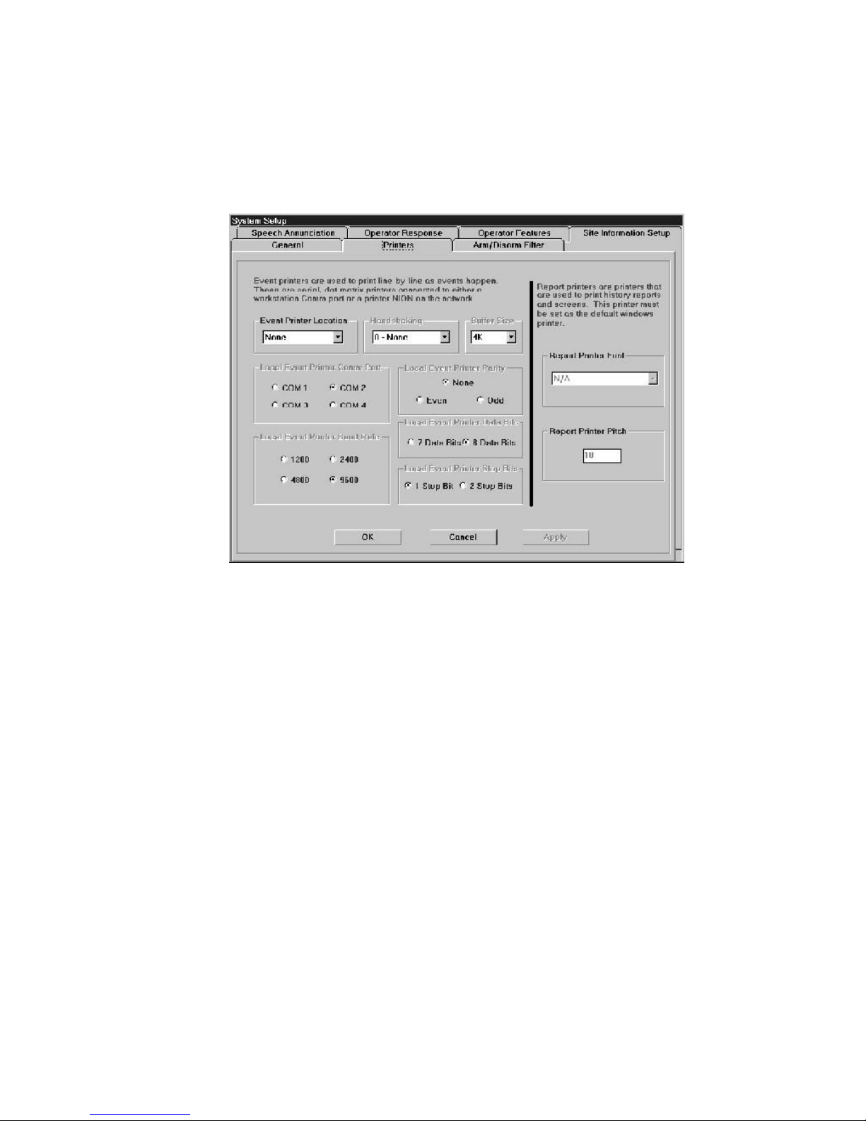
• Suppress Automatic Device Icon Creation for New Devices - When activated, this prevents the
automatic creation of new device icons when events are annunciated. New devices can still be created
manually, and existing devices will function normally.
• Database Synchronization Enabled- When this box is checked (option enabled), databases on
remote workstations will automatically be synchronized with this workstation when database changes are
made.
Figure 1-19: System Options: Printers Tab
Printers Tab
The Printers Tab contains all the setting information to configure a local event printer and a report printer. The
local event printer runs from a COM port on the computer. Report printers are configured through Windows (using
an LPT port), and whatever printer is set up as default will operate as the report printer for the workstation.
The Printers Tab is divided into two separate sections, one for event printers and one for report printers. When
configuring an Event Printer, in the Event Printer Location box, select Local (the options are local and none).
Once this location has been selected, the rest of the box becomes active. Refer to the printer's documentation for
printer specific information.
• Local Event Printer COM Port - This option tells which COM port connection is used by the local
event printer.
• Local Event Printer Baud Rate - Selects the appropriate baud rate for communication between the
computer and the printer.
• Local Event Printer Parity - Specifies the Parity Type for the event printer: None, Even , or Odd.
• Local Event Printer Data Bits - Selects either 7 or 8 bit data bits.
• Local Event Printer Stop Bits - Selects either 1 or 2 bit stop bits.
The Report printer is configured through Windows as the standard Default Windows Printer. In addition, though,
two options are provided here; Report Printer Font and Report Printer Pitch. These two settings tell the
software what font and what dot pitch to use when printing standard text.
The Workstation Installation/Operation Manual Version 2 Document 51540 Rev. B1 4/8/02
31
Page 32

Speech Annunciation
Because of its depth and complexity, the Speech annunciation portion of this software is covered in Section 3.5.6
Creating and Assigning Voice Annunciation Files.
Figure 1-20: System Options: Speech Annunciation Tab
Operator Response Tab
The Operator Response Tab allows the definition of custom fields that an operator can use to enter response
information that will be recorded to the History File for later viewing.
Figure 1-21: System Options: Operator Response Tab
This tab contains 8 cells for entering a line of text. Text entered into these fields will be displayed on the operator
response form as checkbox options. The information selected will then be recorded to the history file.
32
The Workstation Installation/Operation Manual Version 2 Document 51540 Rev. B1 4/8/02
Page 33

Operator Features Setup Tab
The Operator Features Setup Tab contains configuration tools for enhancements covering operator log in and
supervision of operator performance.
Figure 1-22: System Options: Operator Features Setup
• Use Unacked Event Supervision - When this feature is enabled, the workstation supervises operator
acknowledgement of new events. In security circles, this feature is commonly known as a "Dead Man."
When enabled, this feature monitors the New Event box status and activity.
When an event appears in the New Event box, a timer is started which will run for a user defined time (3 60 min.). If the operator acknowledges an event before the timer expires, no action is taken. If any other
events are outstanding in the New Event box, the timer is reset and starts again; otherwise, it is canceled.
If the timer expires before an event is acknowledged, then a user defined macro is executed. This macro
either activates or deactivates an output on the network (also user defined). When executed, this macro
creates an event when the output is activated/deactivated. The output can be used to trip any external
device (horn, strobe, pager etc...) provided by the installer. Once all New Events are acknowledged, a
second user defined macro is executed which contains the converse commands of the first macro.
To configure this option, enter the supervision time in the Unacked Event Timeout field. Select the
predefined macros from the list boxes for Macro Activated on Alarm and Macro Activated on
Alarm Restore. For more details on defining macros, refer to section 3.5.4 Using Macro Editor.
• Shift Change Configuration - Enabling this feature provides a simplified login in process for a four
shift operator duty cycle. Select a different operator name for each shift from the operator account pool.
Then, these operators can log in by simply clicking on the Shift Change button on the Operator
Login form, or you can assign the shift change function to a function key allowing the operators to log in
by pressing the allocated F-key. If the Automatic Shift Changes option is enabled, then assigned
operators will be logged in automatically at the times assigned for each shift.
Site Information Setup Tab
The Site Information Setup Tab allows you to add custom fields to the Site Information display. These
are text fields and can be used to add non-software related informational fields related to the site such as address,
contact numbers, special notes, etc. Fields are added here in the same manner as the Member Information
Setup Tab. Only text field types are available.
The Workstation Installation/Operation Manual Version 2 Document 51540 Rev. B1 4/8/02
33
Page 34

Figure 1-23: System Options: Site Information Setup Tab
The Site Information Setup Tab allows you to define only text-based fields. These fields can be up to 80
characters in length.
To add a new field:
1. Type a description under Field Description.
2. Enter the field length in the Length area.
3. Select OK or Apply to implement the changes.
Arm / Disarm Filter Tab
The Device Types box lists all network device types. This form allows the user to filter device arm/disarm status by
type from the Arm/Disarm Event display. If an entry is checked (default), then devices of that type will be
included in the display. To filter device types from the display, simply uncheck them (left click), then click the OK
button when all desired selections are made.
Figure 1-24: System Options: Arm/Disarm Filter Tab
34
The Workstation Installation/Operation Manual Version 2 Document 51540 Rev. B1 4/8/02
Page 35

Part 2
Operation
The Workstation Installation/Operation Manual Version 2 Document 51540 Rev. B1 4/8/02
UniNet 2000
35
Page 36

NOTES
36
The Workstation Installation/Operation Manual Version 2 Document 51540 Rev. B1 4/8/02
Page 37

2.1
Section 2.1: Basic Workstation Operation
2.1.1 The Workstation Main Screen Tour
The main screen of the Workstation can be divided into six primary parts plus pull down menus. The primary
screen parts are:
• Screen Description
• Floor Plan Display.
• Event Display.
• Network Communications Display.
• Graphic Tools Toolbox.
• Toolbar / Operator Area.
• Information Bar
All of these sections are briefly described in the following paragraphs, with the exception of Graphics Tools, which
is covered in the Administration section of the manual, Section 3.3. Figure 2-1 is a sample main screen from the
Workstation:
Network
Communications
Screen
Description
Floor Plan Display
Information
Bar
Graphics Tools
Toolbar /
Operator Area
Event Display
Figure 2-1: The Workstation Main Screen
The Workstation Installation/Operation Manual Version 2 Document 51540 Rev. B1 4/8/02
37
Page 38
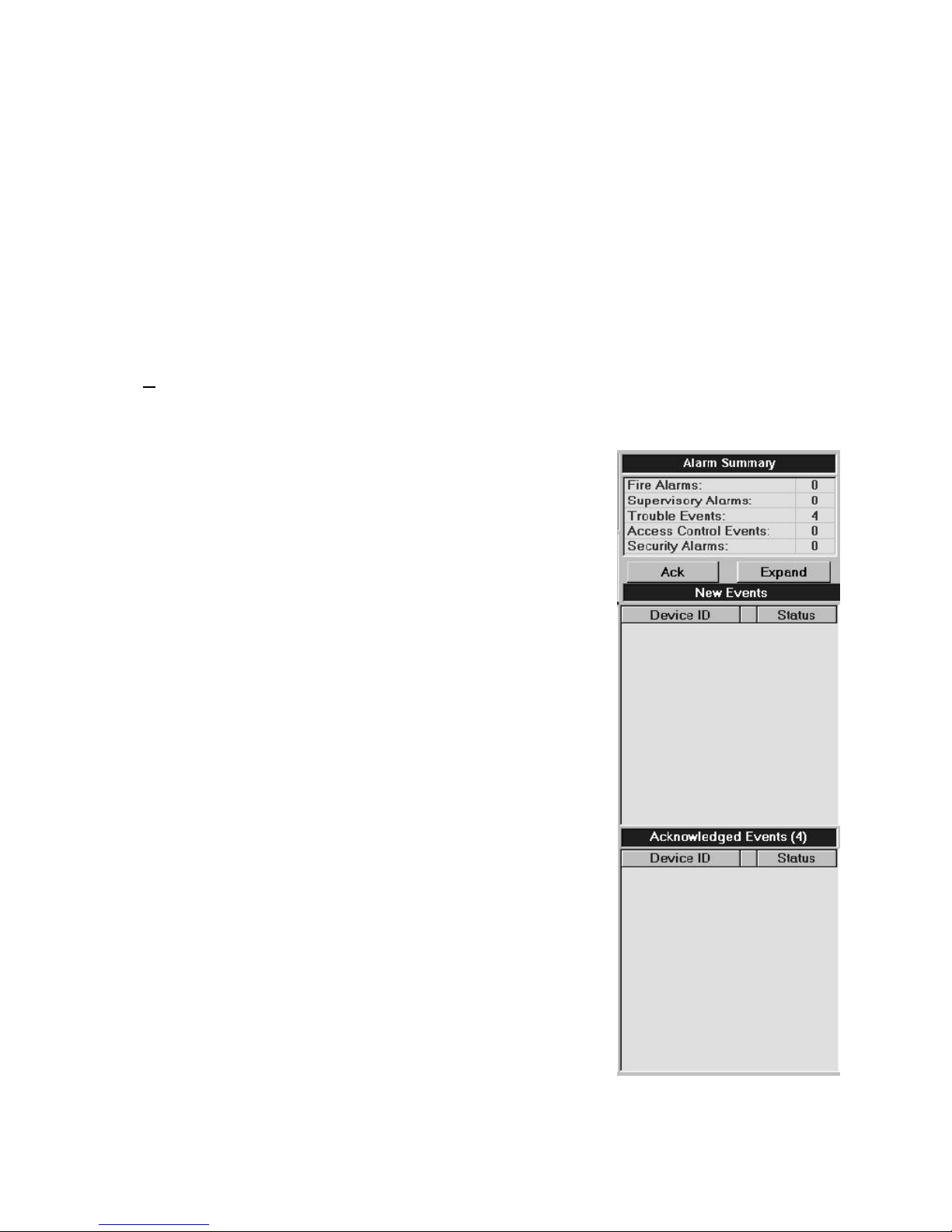
Screen Description
The Site Description, located above the upper left corner of the Floor Plan display, identifies which screen is
currently shown on the Workstation. This description is created in Edit mode by accessing either of the two following menu options:
1. Graphics, Add/Copy Screen
2. Graphics, Edit, Screen Title
Floor Plan Display
The Floor Plan display is the primary source of visual feedback and interaction with the network. The floor plan
display can show any number of screens, each containing one or more devices. Devices include fire panels, fire
protection devices, security devices, cameras, card access stations, and a wide variety of other equipment.
The floor plan display can also contain buttons, which can be either navigational or functional in nature. Navigational buttons move from screen to screen. Functional buttons perform various macro functions such as acknowledging alarms or resetting a panel. Navigation between screens can also be performed manually using the
Screen Navigation pull down menu.
When an event occurs that relates to an icon in the floor plan display, that icon will change to indicate the event.
For example, if a server connection goes into fault, the icon will begin to flash red. In addition, the workstation
incorporates an (optional) Auto-Navigation feature that will automatically
change screens to find the appropriate device related to an event. AutoNavigation works on a priority basis. For example, a trouble on one screen will
not take you away from an alarm on another.
For more information on the floor plan display, see section 2.3: Floor Plan
Display.
Event Display
The event display contains three discrete sections from top to bottom: Alarm
Summary area, New Events box, and Acknowledged Events box.
The Alarm Summary area shows a running total of new and acknowledged
events by type. This tally shows a separate total for Fire Alarms, Supervisory
Alarms, Access Control Events, Trouble Events, and Security Alarms.
The new events box displays events that have been received by the workstation
but not yet acknowledged by an operator. When an event comes in to a
workstation, the workstation will display the event information in the New
Events box and sound an audible alarm at the station. It will also autonavigate to the appropriate screen if priority allows and the option is activated.
Once the operator acknowledges an event by clicking on the ACK button or
the event line, the event moves to the Acknowledged Events box.
For more information on events, the event display, and event handling, refer to
the section titled Event Handling (section 2.2) in the Operations portion of
this manual.
38
The Workstation Installation/Operation Manual Version 2 Document 51540 Rev. B1 4/8/02
Figure 2-2: The Event
Display
Page 39

Network Communications
The network communications box displays basic information relating to the Event Manager, Alarm Servers, and
network traffic. The right side of the box displays the number of Alarm Servers and Event Managers (respectively)
currently on-line.
Immediately below each connection label are send and receive indicators for data transmitted between the alarm
server(s) and the workstation. The number to the right of the Network Communications box ("Queue") shows the
number of inbound messages waiting sent from the Event Manager. Event Manager and Alarm Servers LEDs
display active connections in green. Servers in fault are shown in red. For more information on Event Managers
and Alarm Servers, see section 1.3.1.
Figure 2-3: Network Communications
A Note On Event Manager Synchronization
When Primary and Secondary Event Managers are disconnected and then reconnected, there is a small lag time
before the Event Managers synchronize events (normally just a few seconds, depending on the number of events to
be re-sorted). During this time, new events are still received as normal.
Toolbar / Operator Area
This area of the display contains a variety of different tools. The upper inset box contains the Current Operator
button. Below this button, the name of the current operator is displayed. To the right, the operator's picture is
shown, if available. Clicking on the Current Operator button calls up a dialog box for logging in as a new
operator. This is discussed in the next subsection, Logging into the Workstation.
Below the operator area is another inset box. This box displays buttons for windows that have been moved behind
the current display. If you have a dialog box open and an event comes in, the current window will be moved to the
background, and a button will appear in the inset box. When you click this new button, the previous window will
open. You also have the option of creating custom command buttons under Tools; Command Button
Editor.When the workstation software is initially launched, it contains a button for Msg Window.
Figure 2-4: Toolbar - Operator Area
Information Bar
The Information Bar, located at the very bottom of the Workstation screen, displays the following information at all
times:
• The title of the screen displayed.
• The screen number.
• The type of screen (ie: Title) as it applies to the Screen architecture.
• The Month/Day/Year and current time.
• The zoom level.
The Workstation Installation/Operation Manual Version 2 Document 51540 Rev. B1 4/8/02
39
Page 40

2.1.2 Logging Into the Workstation
When the workstation is started, it begins with the operator account that is currently logged in to the system. This
information is retrieved from the registry and is specific to each computer. If the computer is rebooted, the registry is
cleared, and the workstation is logged in with the Default operator account. This account has extremely limited
access to the system. An actual operator must log in to have access to functions assigned to him/her by the system
administrator. An operator's access also determines which pulldown menus and options are visible. To log in, click
on the Current Operator button in the Operator Area of the main screen. This will activate the Operator
Login dialog box.
Click here
to log in
Figure 2-5: Operator Login
This dialog box is used to select the operator and log in to the workstation.
Available
Operators
List
Operator
Photo
Password
Entry Box
Optional
Admin
Password
Entry Box
Figure 2-6: Operator Login Dialog Box
On the left side of the Operator Login dialog box is the Available Operators list. This list box shows all the currently defined operator accounts. These accounts are defined by the system administrator, and each account has
an associated password and an optional photo. To log in, select the appropriate operator from the Available
Operators list, and then click on the Password Entry box. Now type in the password for the selected operator and
click OK.
If the secondary password feature is enabled, the administrator will require a second password to allow for complete, unrestricted access to the application. All other operators will have only one password, which is assigned
and configured by the administrator. Secondary passwords are configured with the Global Profile Editor. Refer to
the System Utilities manual for more information.
The Operator Login dialog will close and the Operator Area of the main menu will now display the newly
logged in operator's name, and if available, a photo. The operator is now ready to use the workstation system.
To log out the current operator and log in the Default operator account, click on the Logout button.
If Shift Change Operators have been configured, they may be logged in manually be clicking on the Shift
Change button. Clicking the Shift Change button logs out the current operator and logs in the next shift change
rated operator in sequence. For more information on shift change operators and their configuration, refer to
section 1.3.2 The System Setup Folder - Operator Features.
40
The Workstation Installation/Operation Manual Version 2 Document 51540 Rev. B1 4/8/02
Page 41

2.2
Section 2.2: Event Handling
2.2.1 About Events
An Event is any change in the status of a device or a transfer of information between a device and the workstation
or between two devices. Some of these events are considered background and housekeeping events and are not
seen by the user. The events that are of primary concern to the operator are those identified as Off-Normal
Events.
An Off-Normal Event is an event that indicates activity or change in condition requiring the attention and/or
response of an operator. Examples of possible off-normal events include:
• A change in condition or activation of a monitoring device (Motion Detectors, Smoke Alarms, etc.).
• An invalid card swiped through a networked card reader.
• A door is ajar.
• A NION becomes disconnected from the network.
• A Monitoring device is disconnected from its monitoring NION.
Off-normal events seen by the operator can be grouped into two categories:
• Paired Events - Events which after acknowledgment still require another event to return the associated
device to its original state. This second event may be initiated by the operator (as in the case of sending a
reset to a device or panel), or initiated by the original device itself (such as an alarm server which
originally went off-line and is coming back on-line). Devices can send more than one off-normal event
before the related return state event is sent. For example, a fire panel may have more than one alarm state,
and these will not clear until all events have cleared and the panel reports an all clear state.
• Single Events - A single event that, once it is received, leaves the sending device in the same condi-
tion that it was in originally. A good example of a single event is a card access event, which does not
actually change the status of the device.
2.2.2 Types of Events
Events which come into the workstation and are displayed in the event box on the main screen can be divided into
five fundamental categories:
• Security Alarms - Events issued by security related devices such as motion detectors, glass break
detectors, and door contacts.
• Fire Alarms - Events issued by fire protection related devices such as pullstations, smoke detectors,
and sprinkler systems.
• Supervisory Alarms - Supervisory alarms are special alarms to indicate action that has functionally
disabled a key device (for either fire protection or security). An example of this is the event generated if the
water valve is shut off for a sprinkler system.
• Access Control Events - Events issued by card access reader panels, such as a card swipe event or
an invalid card read.
• Trouble Events - Trouble events indicate a functional problem with a device on the network.
Examples of trouble events include a device or workstation going off-line, a battery low or no power event,
a clogged head on a smoke detector, etc.
The Workstation Installation/Operation Manual Version 2 Document 51540 Rev. B1 4/8/02
41
Page 42
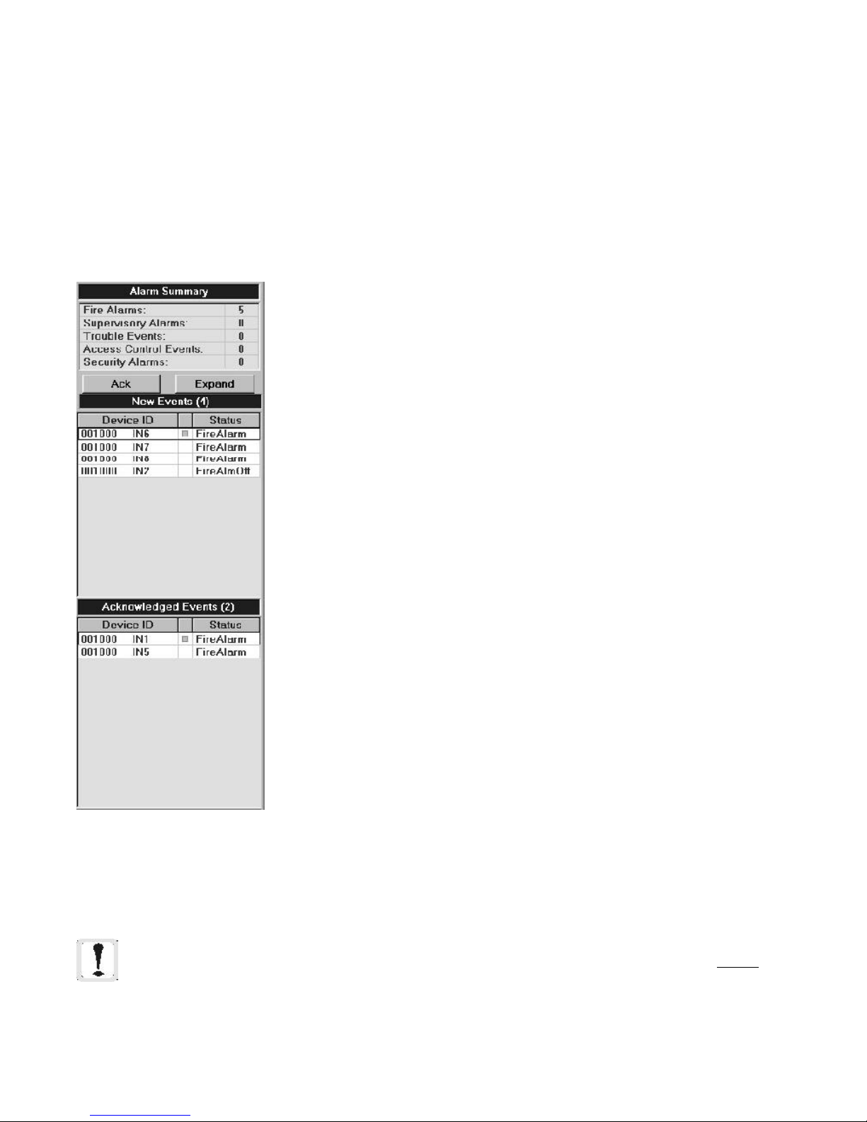
2.2.3 Event Handling
When the Event Manager sends an off-normal event to the workstation, the event is placed in the New Events list
box on the main screen. It remains there until it is acknowledged either locally or by another workstation on the
network which is controlling the device. The Alarm Summary list above the new event box provides a count of
the events received of each type.
When there is an event in the New Events box, an audible alert is sounded on the computer. If auto-navigation is
activated on the device in question, the screen display will move to show that device (unless there is an alarm of
equal or greater priority that has not yet been acknowledged). Events are ordered in both event boxes based on
priority to ensure that an operator deals with the most urgent alarms first.
To acknowledge an event in the new event box, you can do one of three things:
1. Click on the ACK button in the Event Display. This will acknowledge the top
(highest priority) event in the New Events box.
2. Click on the event itself in the New Events box in the Status column.
3. Use a functional button or hotkey that has been defined to send an acknowledgment to some or all devices.
The following options are also available from the Event Display.
New Events
Double left clicking on either column acknowledges the event and navigates to
the screen the device is on.
The Device ID column:
--Single left click - produces a button next to the device. When clicked, it opens
a detailed information box for that event and device.
--Single right click - opens the pop-up menu associated with the device.
The Status column:
--Single left click - acknowledges the event.
Acknowledged Events
Double left clicking either the Status or the Device ID column navigates to the
screen the device is on.
The Device ID column:
--Single left click - produces a button next to the device. When clicked, it opens
a detailed information box for that event and device.
--Single right click - opens the pop-up menu associated with the device.
Clearing A Single Event - To clear a specific event, right click on the desired
event, then select Clear Event from the menu.
When an event is acknowledged, if it is a paired event, it moves to the acknowledged event box where it stays until the related event is also received and acknowledged. If the event is a single event, it disappears when acknowledged,
since single events do not represent a lasting change of condition.
Once a device status is returned to normal (usually by receiving the related pair
event, such as a fault event and a fault-off event), its entry in the Acknowledged
Figure 2-7: Event
Display Box
Events box will disappear.
Alarm states are the exception to this rule. These states will stay in the event box
until the panel associated with these states is reset. This is because the alarms
actually latch at the panels, and the operator should be aware that the panel
requires a reset. Alarm-off states that have been acknowledged will clear once
the panel is reset and all panel states have returned to normal.
NOTE: If a device is acknowledged at a workstation, it is only acknowledged locally and does not
actually affect the device or other workstations on the network unless the current workstation has control
of the specific device. This is not generally an issue in single workstation setups, but for multi-workstation setups, please refer to the control profiles section of the operators manual for more information on
the control of devices.
42
The Workstation Installation/Operation Manual Version 2 Document 51540 Rev. B1 4/8/02
Page 43
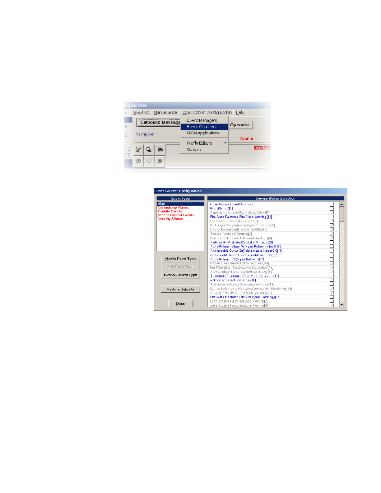
2.2.4 Configurable Event Counters
The Configurable Counters feature of the Workstation allows users to configure the Event Counters section of the
application. In previous versions of the Workstation, the Event Counter would list Event Statuses such as Alarm,
Trouble, Security, Supervisory, and Access Control Events. This new feature allows users to configure both the name
of the counter (limited to five counters) and the Event Statuses that are counted in each catagory.
To begin using the Event Counter Configuration utility, select Event Counters in the drop down menu under
Workstation Configuration. This will open the screen titled Event Counter Configuration .
Figure 2-8: Starting Configurable Counters
The Event Counter Configuration
interface enables the user to define
which Event Counters will be displayed at the Workstation. This
interface allows the user to specify
exactly what qualifies as an event in
each event catagory. The user also
has the option of configuring the
name of the counter (maximum of 25
characters). The workstation will
display a total of up to 5 Event
Counters.
Modifying, Adding, and Removing Event Types
The Event Counter Configuration tool allows the user to modify, add, or remove event types in the Event
Counters area in the upper right corner of the Workstation.
To modify an Event Type, select the desired catagory in the upper left box. Once highlighted, select the Modify
Event Type button below the Event Type list. This will bring up a text box with the prompt Enter Event Type
(25-Char Max). In the open text field type the name of the Event Type being created. When complete, select
OK.
To add a new Event Type, there must be less than 5 Event Type catagories already in place. The Event Counters
area of the Workstation is limited to no more that 5 Event Types. If 5 Event Types already exist, one or more must
be chosen to be removed before more can be added. To remove, highlight the Event Type, and select Remove
Event Type from the buttons below the listing box. This will remove the highlighted item out of the Event Type
box.
To add a new Event Type, select Add Event Type from the buttons below. This will bring up a box similiar to the
Modify Event Type box. Name the Event Type in this box.
The Workstation Installation/Operation Manual Version 2 Document 51540 Rev. B1 4/8/02
Figure 2-9: Configurable Counters
43
Page 44

Figure 2-10: Modifying/Adding an Event Type
Restoring Defaults
The fourth selection under the Event Type box is a button titled Restore Defaults. This will repopulate the Event
Type box with the 5 default settings: Fire Alarms, Supervisory Alarms, Trouble Events, Access Control Events, and
Security Alarms. All settings within the default catagories will be restored as well.
2.2.5 Getting More Information about Events
You can double click on a device appearing in the Event box to navigate to the screen containing the device.
NOTE: If an event is unacknowledged, this will acknowledge the event.
If more off-normal events are received than can be displayed in the event box, the user may choose to expand the
event box to display additional off-normal events. The Expand button, located at the top of the event box,
displays the Off-Normal Events in a list. This list displays all current off-normal events in the system in a treelike
fashion organized by node or group (see figure 2-8).
Figure 2-11: Expanded Event Box
44
The Workstation Installation/Operation Manual Version 2 Document 51540 Rev. B1 4/8/02
Page 45

2.2.6: The View Latest Events and Messages Window
The View Latest Events and Messages window provides the user with information about system events. This
display can be filtered for the following types of events:
• system events applying to the software
(default, not de-selectable).
• fire related events.
• security related events.
• access control related events.
• discrete I/O events.
• environmental events.
• reporting terminal events.
NOTE: When a new filter is selected, it takes effect
for all new events printed to the window. Filters
cannot be applied to events already displayed.
To view the View Latest Events and Messages window, click on the Msg Window button in the toolbox section.
The message and priority are given along with a time and date stamp. Click outside the message box to send it to
the background. To set filters, select the Filters option; clicking on each option will select/deselect it. The default
setting is to show all events. When you click on an event type, and the corresponding check disappears, that event
type will no longer appear in the message window.
The Window menu option includes the following:
Always Show Window - Selecting this will keep the message window activated at all times. Clicking
outside the message window will gray it out, but it will remain on top of the Workstation screen.
Close Window - Click on this option to minimize the message window. A shortcut button will still be visible
in the Toolbar/Operator area of the workstation screen.
• power supply events.
• analog events.
• lighting event.
• Event Manager updates.
• acknowledgments.
• Show All Events.
• Show No Events.
Figure 2-12: Latest Events and Messages Window
Logging
Message logging is available for troubleshooting system problems. The Logging menu item provides the options
Toggle Network Echo and Toggle Network Logging. The echo option displays all network messages received by the
workstation in the window. Most of these messages would normally not be seen by the operator. The logging
option also writes these messages to a log file whose name is the current date in MMDDYYXX.log format (i.e.. Mar
30, 2001's backup would be 033001XX.log) and places the file in c:\uninet\ws. When making multiple backups
in the same day, the log file for that day simply gets appended rather than a separate log file being created.
NOTE: This option should only be used if instructed to by a factory support technician.
The Workstation Installation/Operation Manual Version 2 Document 51540 Rev. B1 4/8/02
45
Page 46
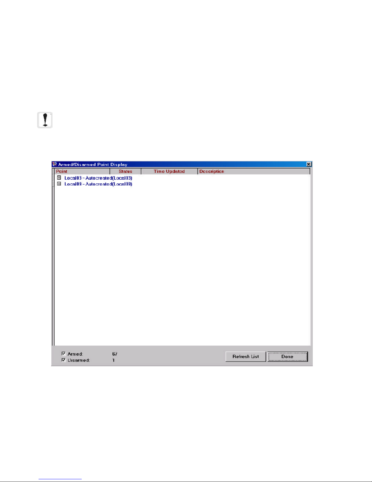
2.2.7 Armed / Disarmed Points Display
The Armed / Disarmed Points display is accessible from the View menu. This form provides a complete list indicating which points are currently armed (coded in red) or disarmed (coded in blue). Every point is displayed by either
its native address or the display ID according to how the workstation is currently set. In addition, any description
defined for the point is displayed, as well as the time of the most recent update.
When both Armed and Disarmed are checked, all addressed points are displayed. Unchecking one of these boxes
will filter out those points from the list (e.g., if you uncheck Armed, only the Disarmed points will be displayed in
the list.).
NOTE: In order for the workstation to track the state of armed and disarmed points in this display, the
point must exist as a graphic device in the screen database. Points defined as text only cannot be
tracked here.
Figure 2-13: Armed / Disarmed Points Display
46
The Workstation Installation/Operation Manual Version 2 Document 51540 Rev. B1 4/8/02
Page 47
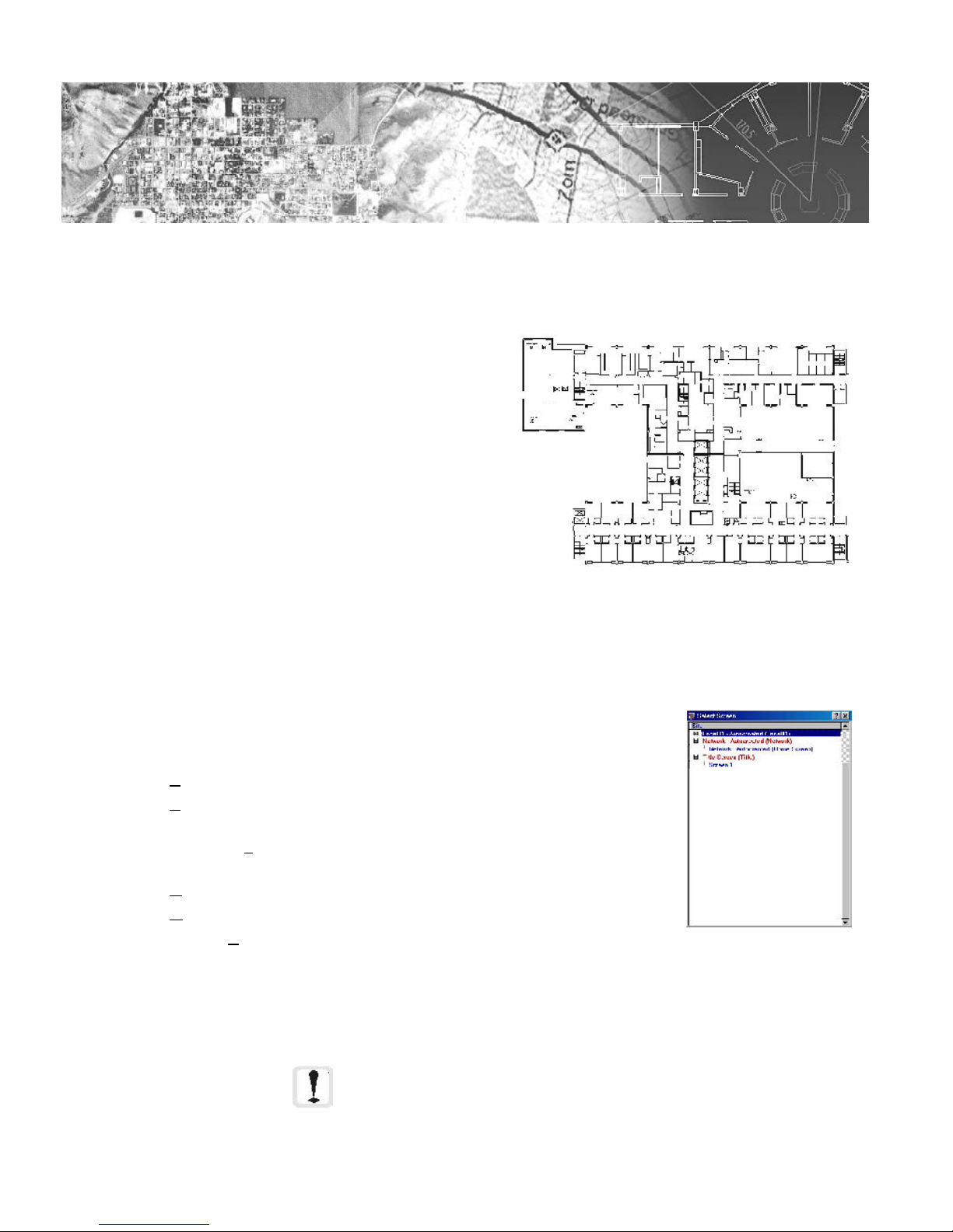
2.3
Section 2.3: Floor Plan Display
2.3.1 Introduction to the Floor Plan
The Floor Plan Display provides a graphical context for the
devices on the network, showing their location on a building
floor plan. It can also display informational icons for items
such as biohazard warnings and various other cautions.
The floor plan area can be used to display front end screens
for navigating the screen database and device network.
Screens can interact using a variety of methods depending
on the situation and environment of its usage.
Buttons on the floor plan allow the operator to either
navigate between the screens and sites of the database or
perform a number of defined macros to communicate with
devices on the network.
Screen Navigation
There are many different ways to navigate through the screens and sites on each network. Buttons allow navigation between screens. Clicking on a navigational button will load the appropriate screen based on how the button
was originally configured. The system administrator has the ability to label these buttons for clarification.
Figure 2-14: Floor Plan Display
It is also possible to navigate through screens with the Screen Navigation
submenu (on the main screen). The options on the Screen Navigation menu are as
follows:
• Front Screen - Navigates to the first (title) screen.
• Previously Viewed Screen - Goes back to the last screen loaded in
the display.
• Previous Screen Number - Moves backwards one screen (numerically).
• Next Screen Number - Moves forward one screen (numerically).
• Go To Screen - Prompts to type in a screen number to load.
• Screen Titles by Site - Calls up the Select Screen dialog. This dialog shows the hierarchy of sites and
In addition to the above , it is also possible for the system administrator to map screen
navigational control to a keyboard function key (see section 2.4.2) or command button
(see section 3.5.3).
screens and allows the user to pick any screen to view (see figure 2-12).
NOTE: The more objects that are placed on a screen,
the more time it takes for that screen to load. The use
of background graphics will also affect the loading
time.
The Workstation Installation/Operation Manual Version 2 Document 51540 Rev. B1 4/8/02
Figure 2-15: Select
Screen Dialog
47
Page 48

2.3.2 Contents of the Floor Plan Display
The floor plan display is a highly detailed canvas that allows the workstation to function within a wide range of
applications, scales, and environments. This section will detail the different types of objects on the display and
examine situations in which they might be found.
The floor plan display can contain three different classes of objects:
• Devices - Devices include a number of different types of objects and can be divided further into six
different types of graphical (floor plan based) devices:
- Addressable Discrete Devices
- Addressable Analog Devices
- Functional Buttons
- Navigational Buttons
- Site Annunciation Icons
- Information Labels
• Vector Graphics - Vector graphics include a number of different graphical objects including:
- Non Device Text
- Line Based Vector Objects (Lines, Boxes, Ellipses, and Arcs)
- Bitmaps (Bitmaps mapped to vector boxes)
• Background - The background can be one of three types:
- Blank
- Imported Bitmap (.BMP)
- Imported Windows MetaFile (.WMF)
These three primary elements and their subcategories form what is seen on various screens in the floor plan display.
Some elements are more common than others, but we will look at all of them to provide a full overview.
Addressable Devices
Addressable Devices represent physical real-world network devices that are monitored by the workstation. These
include various monitoring devices such as motion detectors, pullstations, and door sensors. Addressable devices
also include NIONs, servers, and other workstations on the network. Almost any physical networked device falls
into this category.
There are two different types of Addressable Devices: Discrete and Analog.
Discrete devices are monitored nodes, NIONs, and panels with defined (discrete) states or conditions. These
conditions are annunciated at the workstation. For example, a pullstation either reports a normal state, an alarm
state, or a trouble state. Normal state indicates normal operation, Alarm state shows that the pullstation has been
activated, and a Trouble state indicates a functional problem with the device.
Analog Devices are devices with one or more continuously variable values that are translated into states by the
workstation software based on configurable ranges. An example of an analog device is an environmental sensor,
which continuously reports values such as temperature. Depending on the configured ranges, the workstation will
indicate various states for the device.
Addressable devices have pop-up menus activated by right clicking on the device that allow to view device properties and descriptions, execute macro code to perform device specific operations
(for example, acknowledge a device, reset a panel, etc.), and view linked text,
video, pictures, and sound. An operator can also enter a custom response entry
to a fault from the device. For more information on Pop-Ups, see the Device
Pop-Ups subsection.
Left clicking on a device zooms to place the device in the center and at its native
zoom level.
Figure 2-16: Sample
Pop-up Menu
48
The Workstation Installation/Operation Manual Version 2 Document 51540 Rev. B1 4/8/02
Page 49

If the proximity display option is turned on, an information
window appears when the mouse cursor is placed over an
addressable device. This window displays the Device ID,
description, and type (shown in Figure 2-17).
Devices have two IDs. One is the Device ID, which is the
actual network address of the device. The other is a Display
ID, which is completely definable by the system administrator
Figure 2-17: Sample Information
Window
and usually represents a real world identification of the device,
such as "smoke alarm 26" or "East Hall MDet" (Just like the
Device ID, there is a 14 character limit). The operator can
select which ID to display on the floor plan. This option can be
switched in the View menu on the main screen.
Buttons
There are two types of buttons available in the workstation. These two types, Functional and Navigational, are
similar only in appearance. A button can be any selected bitmap that responds to a mouse click. In the case of a
Functional button, clicking on the button will preform a macro function (such as sending an acknowledge to a
device or resetting all fire panels). Navigational buttons on the other hand simply move to a specified screen in the
screen database and are used to create shortcuts for navigating the system.
Site Annunciation Icons
Site Annunciation icons are special device icons that represent the overall condition of a site on the network. Site
Annunciation icons have two states, normal and off-normal. The state of a Site annunciation icon is dependent on
the condition of the devices at the site it represents. If all devices at the represented site are in normal condition,
then the site annunciation icon displays a normal condition. If any device at the site reports an off-normal condition, then the site annunciation icon is displayed in an off-normal condition.
For example, a display can be created on a screen that shows or lists a number of remote BCI sites. Next to each
display or listing is a site annunciation icon that is linked to the site. If any remote devices report an off-normal
condition, then the site annunciation icon associated with that site will go into off-normal, alerting the operator of a
problem at that site.
Information Labels
Information labels are icons with linked text, pictures, video, and sound that represent information about locations
or specific details about areas of the monitored network. Information labels are not actually physical devices.
Examples of information labels include biohazard area designations (including pictures of the area and text
directions for specific instructions and cautions), construction area designations, exit designators, etc. The linked
material of information labels is accessed with the pop-up menu of the icon.
Vector Graphics and Backgrounds
The specifics of various types of vector graphics and backgrounds are of little interest to the operator and are
discussed at length in the administration manual, Section 3.3.
Vector graphics and backgrounds provide the operator with a context in which the devices, buttons, labels, etc.
exist. The most common type of graphics found are floor plans and front end screens.
Floor plans are imported floor plan diagrams of an area monitored by the workstation. These floor plans (like all
screens in the floor plan display) can be zoomed to allow moving from an
overview of the building down to viewing the devices in one area. Zoom can be
performed using the Zoom In, Zoom Out, and Zoom Full buttons in the
common screen tools area (see figure 2-18), or using the keyboard shortcuts
CTRL-I and CTRL-O (for In and Out respectively). The maximum zoom level
depends on the resolution of the screen.
Front end screens are used to create menus and more conceptual groupings of
Zoom In Zoom Out Zoom Full
devices for monitoring in a less direct fashion. Examples of this might be a
building selection menu that had buttons to go to each remote site and site
annunciation icons that displayed the overall status of each site.
Figure 2-18: Common
Tools
The Workstation Installation/Operation Manual Version 2 Document 51540 Rev. B1 4/8/02
49
Page 50

2.3.3 Keymap
The keymap provides either an overview of the currently displayed screen (without devices, buttons, or other objects)
or a predefined bitmap. Open the keymap by selecting View, Keymap from the main screen menu bar, or click
the keymap button in the graphic toolbox.
When the main screen floor plan display is zoomed in and the keymap is not in bitmap mode, a red box on the
overview outlines what portion of the map is currently being displayed. You can return the main floor plan to
100% zoom by clicking the display portion of the Overview display. If the keymap is displaying a bitmap, then
clicking the keymap will navigate to the specified return screen for the current screen.
The Keymap will always stay on top of other windows on the desktop and can be moved anywhere on the desktop
by clicking and holding on the title bar of the window and placing it as desired. The Keymap can be re-sized by
clicking and dragging the lower right corner. The keymap will automatically maintain its proper perspective.
Figure 2-19: Overview / Keymap
50
The Workstation Installation/Operation Manual Version 2 Document 51540 Rev. B1 4/8/02
Page 51

2.3.4 Addressable Device Pop-Up Menus
Addressable Device Pop-Up menus provide the operator with device specific information and controls. The device
pop-up menu is activated by clicking the right mouse button on any addressable device. The menu that appears
depends on the type of device, the situation, and the rights of the user. Some options are common to all addressable devices, and some devices have functions that are device type specific. The following commands are available
for most devices through addressable device pop-up menus, although access can be restricted for some options:
• Description - Selecting Description brings up a small display box which shows the device's provided
description. This may be a description entered by the system administrator or a description read from a
panel on the network.
• Enter Operator Response - This option calls up a form with the option to select among a number of
predefined operator responses for reporting various conditions and operations related to the device. There
is also a custom response field. The selected response is logged to the history file.
• History of Device - Opens the history manager with preset filters to only display the history
information relating to the selected device. Refer to the System Utilities manual for more information on
the History Manager.
• View/Play Text, Bitmap, Video, Audio - If the device has any linked media, an option will appear
on the pull down to view or play the linked file. Devices with linked media have an asterisk next to the
icon on the Floor Plan Display.
• Zoom - The Zoom Commands allow quick selection of various zoom levels as well as the ability to return
to the previous zoom level. When a zoom is performed, the zoom will center on the current mouse pointer
location.
• Acknowledge, Silence, and Reset - These are examples of device specific commands. They are
based upon macros and are definable by the system administrator. An asterisk on the menu next to an
option indicates that control of the device belongs to another workstation. A workstation must have control
of a device to execute device specific macro commands.
Common
Commands
Device
Specific
Macro
Commands
Zoom Commands
(Common to All
Devices)
Figure 2-20: Addressable Device Pop-Up Menus
The Workstation Installation/Operation Manual Version 2 Document 51540 Rev. B1 4/8/02
51
Page 52

2.3.5 Symbol Key
The Symbol Key provides a directory of devices and information labels found on the floor plan display. The
symbol key also allows the operator to change the description of any of the device icons. The top tabs allow you to
select viewing devices (such as, NIONs, Fire Panels, etc.) or information labels (such as hazardous material,
radioactivity, etc.). The symbol key is found at View, Symbol Key on the main pulldown menu.
Figure 2-21: Symbol Key
2.3.6 Linked Information and Guidance Text
Linked Information
Any addressable device or information label on the floor plan can have linked information. Linked information can
be text, video, bitmaps, and sound. To access the linked information on a device (either addressable or an information label), right click on the icon to bring up the pop-up menu and then make the appropriate selection.
Linked text usually provides information about area restrictions, special cautions, etc. Linked bitmaps are often
pictures of the device or the specific device location. Linked video can be demonstrational in nature, such as how
to reset or disable a device. Linked sound is often instructional, but could be used to give example audio alarms.
All of these are only examples and represent some of the more common uses of linked information.
Guidance Text
Guidance text is linked text associated with a specific screen. Usually, as with linked device text, this relates to
special procedures or precautions. Guidance text is different for every screen. The content of the guidance text
window can be anything that needs to be imparted to operators for a specific floorplan. For example: emergency
contact numbers and instructions for building approach and access.
To open the guidance text display for the current screen, select the View, Guidance Text menu option.
52
The Workstation Installation/Operation Manual Version 2 Document 51540 Rev. B1 4/8/02
Page 53
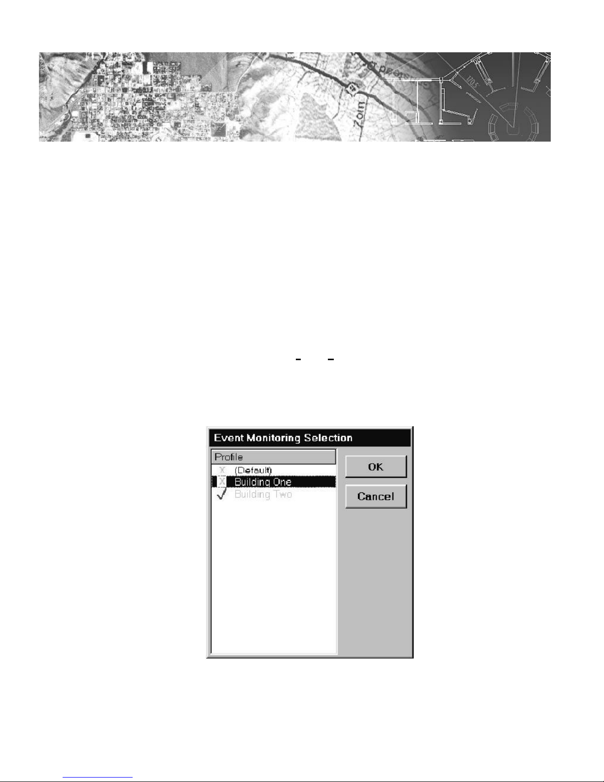
2.4
Section 2.4: Advanced Features
2.4.1 Monitoring and Control Profiles
Monitoring and control profiles allow the operator to select what devices will be monitored and controlled by the
workstation. Each predefined setting, called a profile, is defined by the system administrator for the specific site and
application. Monitoring profiles determine what events are seen by the workstation. Likewise, control profiles select
what devices are controlled by the workstation. By using monitoring and control profiles, supervision of various
portions of the device network can be transferred as needed based on the schedule and needs of the site.
Monitoring Profiles
Monitoring profiles allow the operator to select exactly what events are seen by the workstation, organized based on
selecting specific nodes, subnodes and devices. This specific selection is the job of the system administrator, who
creates a number of profiles that can be selected by the operator. Usually these profiles are created around a
physical or operational structure, such as by building or by work shift.
In order to activate a new profile for monitoring, select Tools, Event Monitoring Selection from the pulldown
menu. This will call up the Event Monitoring Selection dialog box. On the left side of the box is a list of
currently defined monitoring profiles. Any number of profiles can be selected for activation. Select the profile(s) to
activate and click on the OK button. The workstation will now be monitoring the specified areas and/or devices.
Figure 2-22: Event Monitoring Configuration Dialog
The Workstation Installation/Operation Manual Version 2 Document 51540 Rev. B1 4/8/02
53
Page 54

Control Profiles
Control profiles determine which devices the workstation is currently supervising. This is very important because
when a message is sent to a device, or an event for a device is acknowledged, that message or acknowledgment is
only local unless the workstation has control of that device.
Because of the need to be able to respond to problems that may occur in areas that a specific operator does not
always monitor, the operator can change control of specific devices. To change control profiles and control of
specific devices, select Tools, Node Control Selection from the pull down menu. This will open the Control
Profile Select dialog box.
The left side of the Control Profile Select dialog shows the hierarchy of nodes, subnodes, and devices on the
network. Next to each device is the IP address of the controlling workstation. If this address is blue, the local
workstation has control of the device, if it is gray, another workstation on the network has control. To activate a
predefined control profile, select that profile's name on the right side of the screen and click on Activate. The
device display to the left will reflect this control change.
Figure 2-23: Control Profile Select Dialog
NOTE: You can only select control profiles from this screen.
For details on how to define control profiles, refer to section
3.1.4 Defining Monitor and Control Profiles.
You can also take control of a single device, subnode, or node by right clicking on that device and selecting
Activate Control for this... from the pop up menu. This will give the current workstation control over the
selected device(s).
Important Note: Only one workstation can control any
single device at a given time. Taking control of a device
removes control from the previous supervisor of that device.
54
The Workstation Installation/Operation Manual Version 2 Document 51540 Rev. B1 4/8/02
Page 55

2.4.2 Function Keys
Function Keys F2 through F12 are all configurable within the UniNet Software. This allows commonly used
functions to be assigned to the function keys for easy access. Configuration of the function keys is an assignable
security privilege, but generally the system administrator will define their function. The workstation has a toolbar for
function keys which displays the 12 keys and a description of what the key has been assigned to do. To activate
the toolbar, press CTRL-H on the keyboard. Although F1 is listed in the Toolbar, its function is always predefined
to activate the On-Line Help.
Function keys can provide the following features (when configured by the System Administrator):
• Navigate to a specified screen
• Acknowledge Event
• Operator Login
• Toggle Keymap
• View Active Alarm Messages
• View Outbound Messages
• Search for Existing Symbols
• View Symbol Key / Legend
• View Site Information
• Activate Messages Window
• Activate Expanded Event Box
• Image Zoom In
• Image Zoom Out
• Image Zoom Full
• Toggle Edit Mode
• Toggle Function Key Help Bar
• Map Devices(s) w/ Pop Up Menu Options
• Log Out
2.4.3 Printing in the Workstation
The workstation has numerous locations where you can print a variety of information. All the different printer
options (with the exclusion of the event printer) use the same settings derived from the File, Print, Printer Setup
menu option. This displays the standard Windows printer setup form.
You can print the floor plan by clicking on the Print icon in the graphics toolbox. This will print the floor plan
display area as it currently appears, headed by a section w/ screen title, site information, and screen information.
From the Printing menu (at File, Print) there are four available options:
• Printer Setup - Sets up the printer with the standard Windows printer setup form. Allows setting of
general options plus selection of the printer to be used.
• Print Device List - Allows the operator to print a list of devices programmed in the workstation sorted
by device ID or device type. The list can be of all devices or just devices on the currently viewed site.
• Print Floorplan area - This does the same thing as the print icon in the toolbox. It prints the floor
plan and a header of description information.
• Print Events - Prints a report of outstanding events. In addition, the operator may choose to print
unacknowledged events only, acknowledged events only or all events.
The Workstation Installation/Operation Manual Version 2 Document 51540 Rev. B1 4/8/02
55
Page 56

2.4.4 History Manager
The History Manager is a utility for viewing all of the events that are currently stored in the history database of a
network client application. It serves as a database manager which can organize all events which pass through the
main software application. The History Manager allows a complex set of filters to be applied to the events in order
to view the history for specific event types, devices, and events for specific dates.
There are three ways to access the History Manager:
1. Select Tools...History Manager within a network client (such as the workstation)
2. From the desktop, select Start...Programs...Uninet...History Manager .
3. Right click on a device and select View History.
When first launched, the History Manager displays events in the database. The information bar at the bottom of
the screen displays the number of entries within the database, which events are being shown, the date and current
time.
Figure 2-24: History Manager Main Screen
The Event Display Screen
The Event Display shows a list of events in the history file currently being viewed. This can be the current history file
in use by the application (for example: history.mdb) or it can be an archived history file. Color coding of displayed
events can be enabled or disabled at the user's choice for easier analysis by grouping entries by user definable
criteria. This function is accessed through the Configure...Use Color Coding menu item.
The History Manager displays all columns of the database currently being accessed. The information displayed by
the History Manager depends on what specific application provided the database. For example, if the History
Manager was running a UniLogic database, only columns specific to that database would be displayed in the
layout. Likewise, if the workstation database was being accessed by the History Manager, then all columns specific
to the workstation would be shown.
Aside from the different events which are targeted depending on what application is in use, the History Manager
retains a constant color coding system which applies to databases that support color coding. These colors allow
each event to be grouped with a greater prejudice than the variation in events.
56
The Workstation Installation/Operation Manual Version 2 Document 51540 Rev. B1 4/8/02
Page 57

NOTE: For more information on the History Manager application including filter application and report
scheduling and generation, refer to the System Utilities manual.
Figure 2-25: The Event Display
When used with the workstation history database, the Event Display contains nine columns of information (six are
shown above because of screen width). These nine columns are:
• Date/Time (Rec)(Actual): This field displays either the time that the event was received by the worksta-
tion, or the actual time the event occurred. The field can be alternated between received and actual time
using the button in the lower left hand corner of the main screen. The format is MM/DD/YY HH:MM:SS
(AM/PM).
• Site: This field gives the Site ID for the site from which the event was generated. Keep in mind that all
local sites use the naming convention LocalXX, where XX is the server number that monitors that location.
• Device ID: This field gives the device ID of the device that generated the event.
• Status: The Status field gives the status of the device or the nature of the event. Status is where the event
is annunciated in plain text terms.
• Value: This field indicates the value associated with an event. 0 = Off, 255 = ON.
• Device Type: This field gives the device type in accordance with the configured device type inside the
workstation software.
• Event / Msg Type: This indicates the event type in accordance with the event types used in filtering
events. These types are less specific than the device type, but more specific than the color codes.
• Ack: This field contains a checkbox. If the checkbox is checked, then the event was acknowledged by an
operator. If the box is unchecked, it was not acknowledged.
• Text Messages: This field contains text messages associated with an event. System events often contain
informational text in this field. This is also the field where text entered by an operator as an operator
response will appear.
The Workstation Installation/Operation Manual Version 2 Document 51540 Rev. B1 4/8/02
57
Page 58
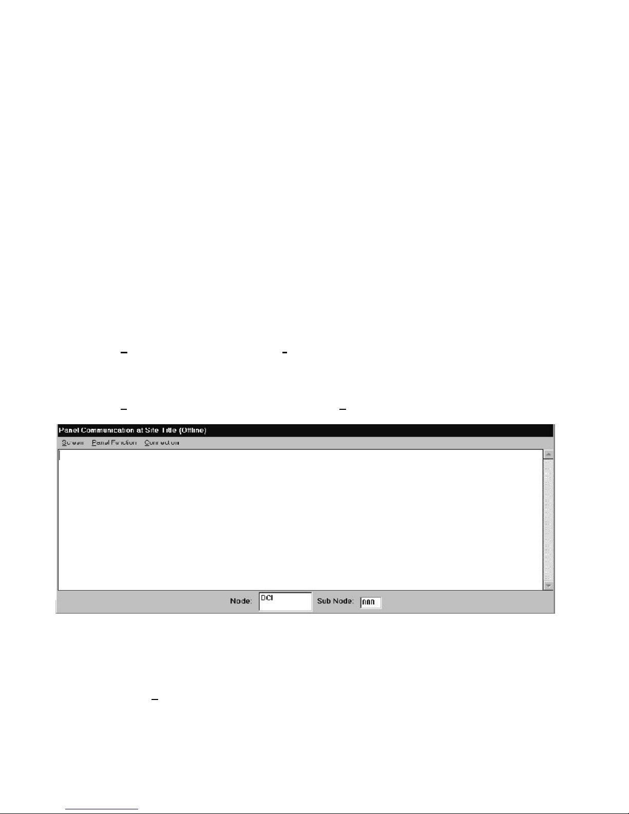
The events are also color coded with the following color scheme:
• Red: Red indicates a critical alarm. These alarms are events that generally require immediate
response and take top priority. Examples include Forced Entry, Door Ajar, and Tour Interrupted.
• Yellow: Yellow events are trouble or fault events, or their paired (inverse) events. These events usually
represent internal or system problems and often require maintenance as a response. Examples include
High Value, Prealarm, and Trouble.
• Gray: Gray events indicate resets or return to a passive/normal state. Examples include reset and
Panel Normal.
• Green: Green events are events that indicate by their presence a normal condition of operation.
Examples include Accepted, Guard Tour Read, and Request to Exit.
• Blue: Blue events are security and supervisory events. Examples include Panel Armed, Security Alarm
Restored, and Test Mode Terminated.
2.4.5 Panel Communications
The UniNet software allows the operator to communicate with a panel that supports terminal communication and is
connected to the UniNet system through a Serial NION. To communicate with a specific panel:
• Go to the screen for the site with which you would like to communicate. Keep in mind that if the site you
select is a remote site, the workstation will have to dial out to the site for the panel communications
session. These sessions will operate more slowly than a local session.
• Select Panel Communications from the Tools menu on the main screen. The Panel
Communications Session box will appear for the currently selected site (based on the current screen).
• From the bottom of the Panel Communications dialog box, select the Node, and if applicable, the
subnode with which to connect.
• Select Establish Communications Session from the Connection pull down menu item.
Notifier
HVAC NION MAIN MENU
72 F ECON: ON REHEAT: ON 63 %RH
Choose 1-15 >_
Figure 2-26: Panel Communications Session Box
The workstation will now attempt to connect to the selected panel. Once the connection is completed, the display
portion of the Panel Communications dialog will show the ASCII output from the panel, emulating a direct
terminal session. The Panel Functions menu contains a list of functions available for each specific device based
on the plug-in for that device. Fire panels will have options to Acknowledge, Silence, and Reset based on the
generic fire plug-in. Security panels will have at least Arm and Disarm, as well as other functions specific to certain
panels. Refer to each specific plug-in manual for more information on these functions.
58
The Workstation Installation/Operation Manual Version 2 Document 51540 Rev. B1 4/8/02
Page 59
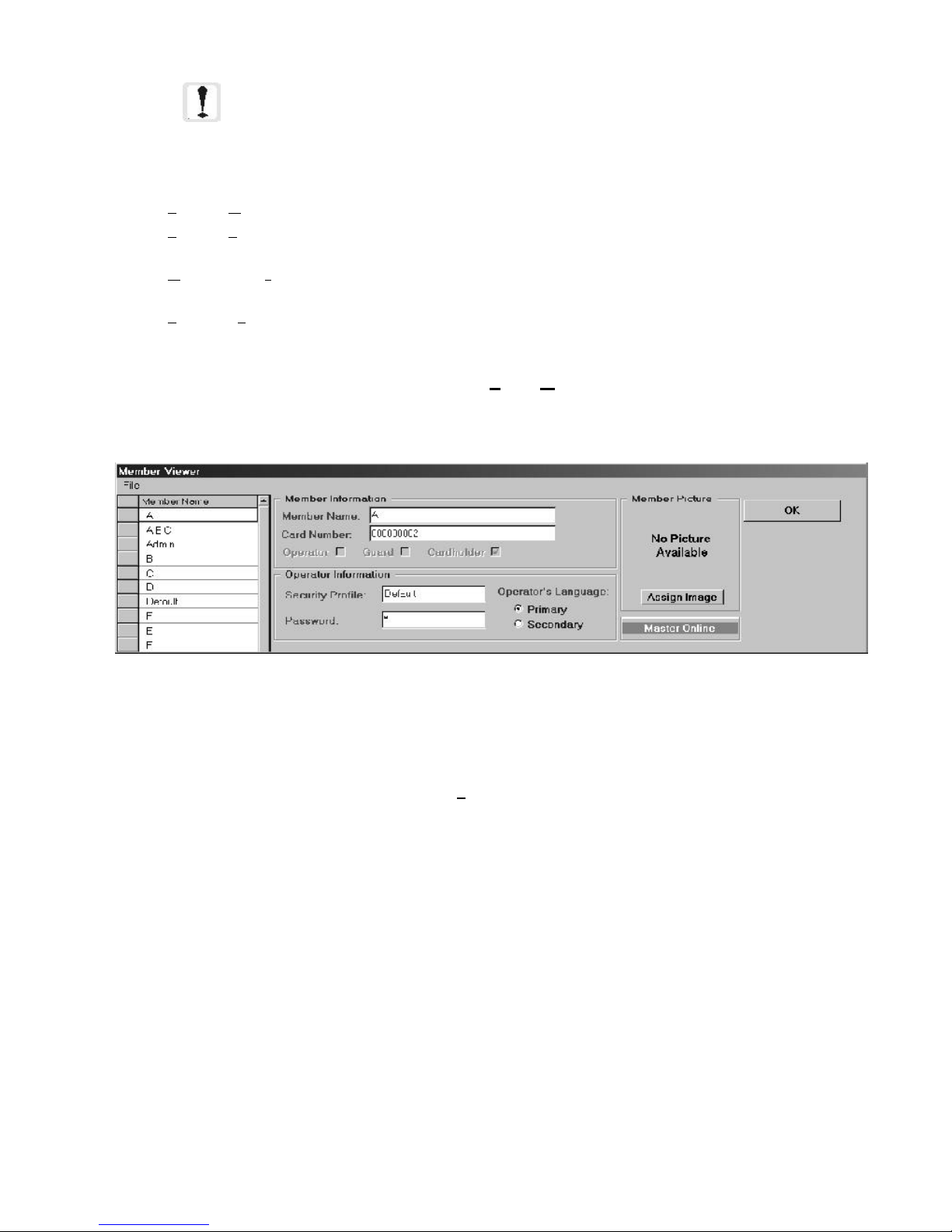
NOTE:The panel communications session is an ancillary feature and is not meant to
be used as a substitute for a dedicated terminal. Terminal functions through this
window may be much slower compared to a terminal connected directly to the
panel.
Other options within the Panel Communications Session box:
• Screen, Clear Screen will clear the ASCII display window.
• Screen, Print Screen will print the ASCII terminal display to the selected printer (see section titled Printing
in the Workstation for more information).
• Connection, Terminate Communications Session will end the current communications session with
the selected node.
• Screen, Exit Panel Communications will exit the Panel Communications Session box.
2.4.6 View Member Information Window
The View Member Information window is located in View, Member Information. This view can be used
to examine the member information database but does not have the facility to add or delete users.
Figure 2-27: View Member Information Window
Card members can be selected from the Member Name list box on the left. The user has the option to search by
member card number instead of name by right clicking in the Member Name list box. This will change the display
to show a list of card numbers for all members. The File menu has an exit option. To exit, you can also click the
OK button at the top right of the form.
The Workstation Installation/Operation Manual Version 2 Document 51540 Rev. B1 4/8/02
59
Page 60
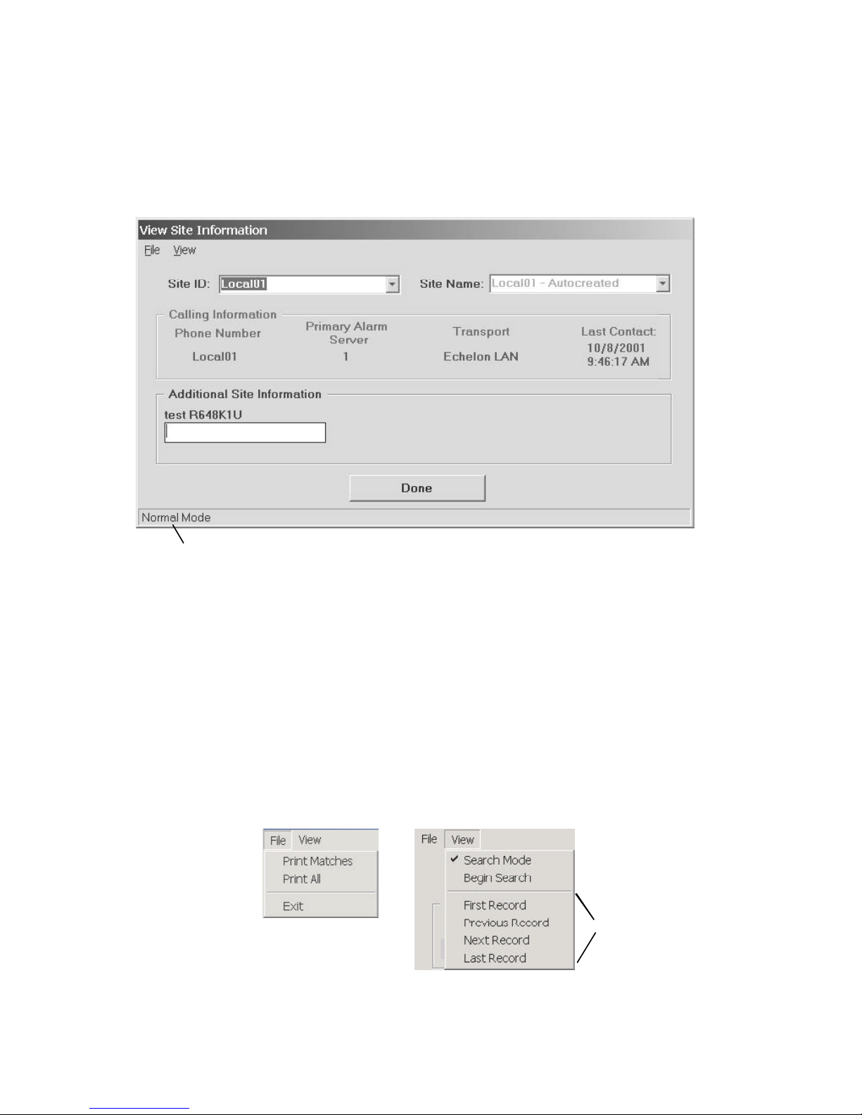
2.4.7 View Site Information
This option allows you to obtain detailed information about a specific site or sites, based on search criteria. To
access this feature, click on View, Site Information. To display information, select by either Site ID or Site
Name. The Phone Number field displays the phone number used to dial that site. The Primary Alarm Server field
indicates which Server is controlling the routing of events from that site. The Transport field displays the type of
phone line over which that site is communicating. The Last Contact field shows the last time that site called in to
the workstation.
This status bar shows
you whether the dialog
is in Normal or Search
mode.
Figure 2-28: View Site Information
If you need to perform a search for a site, once View Site Information is activated, access Search mode by selecting
View, Search Mode. The status bar at the bottom of the View Site Information window will indicate the mode
change. Using the Search feature is most effective when there are user defined fields which have been configured
for displaying custom detailed descriptions to aid in differentiating sites. The Additional Site Information frame is
where these user defined fields are located.
For example, when dealing with a networked college campus, a custom field can be created to describe a site's
physical location, assuming a site represents a single building. The user defined field could then contain entries
like dormitory 1, natural sciences, physical sciences, chemical sciences, basketball gym, etc. Once in Search
mode, you could type in "sciences" to get all sites with that word in that user defined field. You could then select
File, Print Matches to print the information for all those sites, which, using this example, would be natural
sciences, physical sciences, and chemical sciences. Selecting File, Print All will print site information for all sites on
the monitoring network.
When a search produces
multiple results, you can
scroll through them using
these menu options.
Figure 2-29: View Site Information Menus
60
The Workstation Installation/Operation Manual Version 2 Document 51540 Rev. B1 4/8/02
Page 61

Part 3
System Administra-
tion
The Workstation Installation/Operation Manual Version 2 Document 51540 Rev. B1 4/8/02
UniNet 2000
61
Page 62

NOTES
62
The Workstation Installation/Operation Manual Version 2 Document 51540 Rev. B1 4/8/02
Page 63
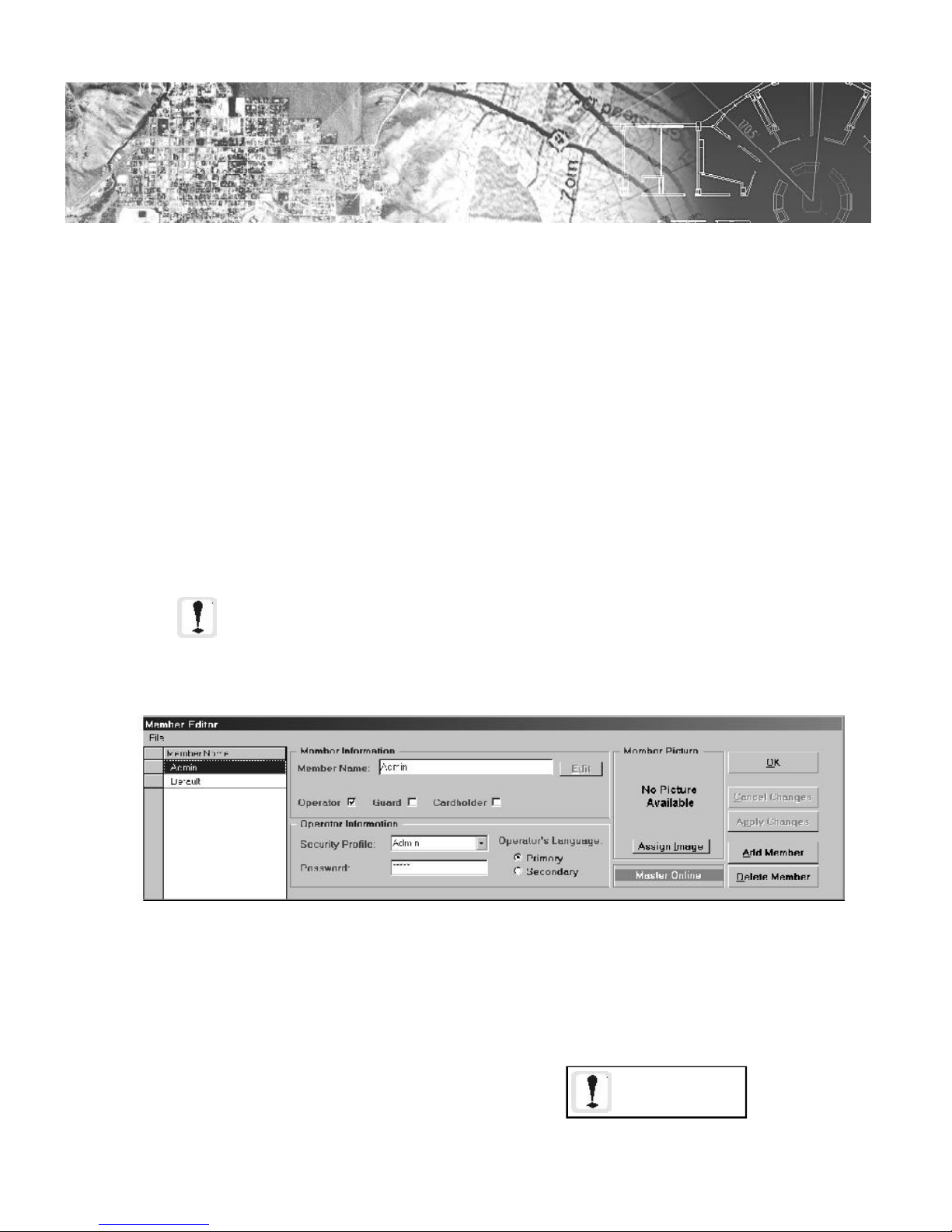
3.1
Section 3.1: User Management
UniNet supports a variety of tools to configure and manage databases for system users, system operators and
administrators. Workstation specific profiles can be defined for the following user categories:
• Security
• Monitoring
• Control
Configuration of each of these categories is explained in the following sections.
3.1.1 The Member Editor and Member Database
The member database contains information on access card holders and system operators. Any workstation can
add, edit or delete information (data) from this database at any time. After changes are made, databases on other
workstations are synchronized to match. Select Tools, Member Editor to add or modify member information.
NOTE: Member Editors of different clients will not have common information unless
Launcher is configured to point them to a common master database. Please refer to
the Systems Utilities for detailed information on this configuration.
Figure 3-1: The Member Editor Dialog
The Workstation Installation/Operation Manual Version 2 Document 51540 Rev. B1 4/8/02
You must hit enter
after typing data in a
user defined text
field.
63
Page 64

Adding a New Member
To add a new member, click on the Add Member button. In the Member Information frame, enter the person's
name using the Member Name dialog. To assign a card to the member, enter the card number in the Card
Number field. This field is only active when the Cardholder option is checked. The admin and default user
names cannot be edited.
Applications prior to 2.1 store member information in one field. From version 2.1forward, these applications have
been changed to having three fields for the name: First, Middle and Last. This change has been made to improve
database processing time and affects any client utilizing the Member Editor (Workstation, UniGuard, and
UniBadge) and the Login screen (all UniNet clients). To convert older databases to a current, three-field database,
use the Database Upgrade Utility, found in c:\UniNet\MasterDB. Double click on DBConvert21.exe, and the
utility will walk you through the upgrade steps. For details about the Database Upgrade Utility, refer to the corresponding section in the System Utilities manual.
Editing Member Names
To edit a member's name, click on the Edit button. This
brings up the corresponding dialog, allowing you to edit the
name that appears in the Member Name list box on the left
side of the Member Editor form. Once the name is edited,
another window activates prompting the user to select the
format to be used for the names that appear in the list box.
Name Formats
There are two format possibilities for displaying names in the
Member Editor's Member Name list: First, Middle, Last
(F,M,L) or Last, First, Middle (L,F,M). Select Change Name
Format from the File menu to perform this function.
Figure 3-2: Member Name and
Name Format
Operator Information
For a system member to be given access to the UniNet user interface, they must be assigned as an operator.
Operators do not need to be assigned an access card to log in to the system. Each operator has an associated
name, password and security profile. Security profiles are defined by the system administrator via either the Global
Profile Editor or the Profile Editor of individual applications.
To assign a member as an operator:
1. Click on the Operator check box. This will enable the fields associated with operators.
2. Enter the operator's password in the Password field (fifteen characters max.). The default password is
"username."
3. Select the desired operator security profile from the Security Profile combo box.
4. Select which language is to be used for speech annunciation with the assigned operator in the
Operator's Language area.
5. Click on OK or Apply Changes to accept, Cancel Changes to abort.
64
The Workstation Installation/Operation Manual Version 2 Document 51540 Rev. B1 4/8/02
Page 65

Digital Images of System Members
A digital image of a member may be included in their record. For operators, this image would be displayed during
login and on the main screen after login. UniBadge can print these imported images on badges. This image is
obtained from a file on the hard drive. To store an image in a member's record, click on the Assign Image
button or right click on the image area, then click on Load Picture From Disk. This brings up a Windows
Open File dialog box. The file can be selected from any available drive. The command copies the file to the
user database. Images can also be captured directly from a digital camera.
3.1.2 Member Editor Configuration
Creating and Editing User Defined Fields
Edit Profiles tab - Select File, Edit User Defined Field Information to access this dialog. From here, you
can assign user-defined-field access levels for the different profiles which have been defined. Adding a new profile
can only be done through the Global Profile Editor. Highlight a profile to assign UDF access levels. You can
choose either editing or view-only access by selecting the desired checkbox for each user defined field. After
assigning all profiles their respective UDF access levels, click on OK to return to the Member Editor screen.
Figure 3-2: Profile Access Editor - Edit Profiles Tab
The Workstation Installation/Operation Manual Version 2 Document 51540 Rev. B1 4/8/02
65
Page 66

Edit Fields tab - This feature allows any user with editing access to
add, remove, or edit user defined fields. To add a new UDF, click on
Add Field. In the corresponding dialog, enter the field name and
choose a field type. If you choose to create a text field (maximum
200 characters), you will be prompted to enter a field size.
There are three possible user defined field types:
Figure 3-3: New UDF Dialog
Figure 3-4: Profile Access Editor - Edit Fields Tab
• Text - an alphanumeric text field.
• Boolean - a true/false field in the form of a check box.
• Picture - a digital image.
To edit a UDF, highlight it in the list, and click on Modify Field. The application will ask if you are sure about
making changes; click Yes, and the following dialog appears:
You can change the field name, type, and if it is a text field, the field size; after these changes are made, click OK
to apply the changes or Cancel to exit without modifying the UDF.
Figure 3-5: Modifying a User Defined Field
NOTE: You cannot change a text or boolean
field to a picture field.
You cannot modify a picture field. It must be
removed and recreated.
66
The Workstation Installation/Operation Manual Version 2 Document 51540 Rev. B1 4/8/02
Page 67

3.1.3 Security and Security Profiles
There are numerous workstation security controls to ensure that the workstation is not disabled by unauthorized
users. Two basic areas of protection are covered:
• Hardware Security.
• Software Security.
Hardware Security
Workstation power connections are secured with special hardware, and the computer power switch is disabled.
With proper line current surge protection and UPS power supply installed, the workstation is well protected from
system failures.
In addition, a dedicated workstation supervisor device is available that monitors its operation through a direct
connection with the motherboard's bus. In the event the workstation goes off-line, either from mechanical/electrical
failure or tampering, an alarm is sounded by the device to notify personnel of monitoring loss. (For more information on the Workstation Supervisor, See Section 1.1.3).
Software Security
Software security provides workstation operation protection through three methods:
• Control/Command Key Lockouts.
• Application auto-start.
• Operator Security Profiles.
Control/Command keys or application switching keys are standard computer commands which provide computer
users convenient methods to shut down and re-boot the computer. Other key commands allow easy access to
system resources and programs outside of the current application. All of these commands can be disabled by the
system administrator.
For details on how to disable application switching, refer to the Launcher section of the System Utilities manual.
NOTE: Changing the application switching setting requires rebooting the computer.
In the event that the system is shut down or re-booted, the monitoring software is set to automatically load during
the start-up process. With the control key lockouts in place, this makes it extremely difficult to circumvent the
workstation.
The Workstation Installation/Operation Manual Version 2 Document 51540 Rev. B1 4/8/02
67
Page 68

Security Profiles
Operator functionality and activity are controlled by the assignment of security profiles. Each operator and administrator is assigned a security profile with their system member record. Security profiles contain a list of all workstation functions where anyone assigned to that profile is allowed access.
Security profiles are defined and maintained by a system administrator using the Security Profile Maintenance
dialog box. This dialog is accessed through the menu selection Workstation Configuration, Profile Editors,
Security Profiles. This is for Workstation specific access configuration. All applications can be configured
through the Global Profile Editor. For details, refer to the System Utilities manual.
The workstation comes with two profiles predefined:
• Administrator.
• Default.
These correspond with matching operator accounts with passwords:
• Admin admin
• Default default
The administrator profile has access to all system functions. IMPORTANT: The default password for the
Admin account should be replaced with an actual operator password to ensure security. The Admin
and Default account is not removable.
NOTE: Passwords are case sensitive.
The Default profile is set with all access to system functions denied. The Default operator account cannot be
deleted as it is used by the system as the Current Operator at system start-up.
Creating and editing security profiles is a simple process. The Security Profile Maintenance dialog contains a
two column list on the left side of the dialog. The left column is the system function category map containing a
hierarchical menu list of all system features. The right column displays the status of each feature for the currently
selected profile, either Denied or Allowed.
The list box on the right side of the dialog contains a list of all defined security profiles. Click on a profile to
display its configuration on the left.
To create a new profile:
1. Click on the Add Profile button.
2. Enter a new profile name. The categories for the new profile will be displayed with all features denied.
3. Under the Title column, click on a feature or feature group to change its status from Denied to
Allowed. Clicking on a feature group header denies access to all features beneath it in the hierarchy.
Clicking on the column header Allowed toggles all features to either Allowed or Denied.
NOTE: Duplicate profile names cannot be created.
68
The Workstation Installation/Operation Manual Version 2 Document 51540 Rev. B1 4/8/02
Page 69

Profile List
Box
Feature Group
Headings
Individual
Features
Figure 3-6: Security Profile Maintenance Dialog
To remove an existing profile, select the profile from the Profiles list box then, click on the Delete Profile
button, and confirm its removal. If any existing operators are assigned that profile, then the workstation prompts for
assignment of new profiles for those operators.
To edit an existing profile:
1. Select the desired profile from the list box.
2. Toggle the status of menus and features under the category heading by double clicking them.
The Copy Profile button creates a new profile with the same access level as the currently selected profile. Once
created, this profile can be edited. This feature is useful for creating multiple profiles with similar access permissions.
The Workstation Installation/Operation Manual Version 2 Document 51540 Rev. B1 4/8/02
69
Page 70

3.1.4 Defining Monitor and Control Profiles
Monitoring and control profiles allow the operator to select what devices will be monitored and controlled by the
workstation. Each profile is defined for the specific site and application. Monitoring profiles determine what events
are seen by the workstation and control profiles select what devices are controlled by the workstation. By using
monitor and control profiles, supervision of various portions of the network can be transferred as needed based on
the schedule and needs of the site (ie. a Security workstation vs a Fire workstation).
These two types of profiles are defined by the system administrator using the tools described in the following
sections.
Monitoring Profiles
Monitoring profiles are configured event annunciation filters that block selected events from appearing on the
workstation. Filters are defined by two methods:
• Event Location.
• Event Type.
These profiles are defined using the Event Monitor Profiles Manager dialog located under the menu
Workstation Configuration, Profile Editors, Event Monitoring Profiles.
NOTE: An open box represents a unselected item while a
check mark represents a selected item.
Monitoring
Profiles List
Box
Site
Node
Subnode
Figure 3-7: The Event Monitor Profiles Manager Dialog
The system comes with a default monitoring profile defined to monitor all devices. Locations can be filtered at three
levels:
• Site.
• Node.
• Subnode.
NOTE: Any device status which is filtered from display at all workstations on the
network must also be purged from the event pool on the event manager. For more
information on event pool configuration, refer to the event manager manual.
70
The Workstation Installation/Operation Manual Version 2 Document 51540 Rev. B1 4/8/02
Page 71

Event types are filtered by the device status. The device status represents every alarm type recognized by the system.
Each profile can be defined to filter alarms system-wide by their status.
Both of these methods can be used in a profile to allow alarms to be filtered for selected types and all alarms to be
filtered for a selected location.
To create a new profile:
1. Click on the Add Profile button.
2. Enter a new profile name. The Sites and Device Statuses for the new profile will be displayed with all
features selected.
To filter by location:
3. In the Site list box, double click on each Site or Node to be filtered or select individual subnodes if
applicable. Double-clicking on a site filters all nodes beneath it in the hierarchy. Double-clicking on a
node filters all subnodes beneath it in the hierarchy.
To filter by type:
4. In the Device Status list box, select each alarm type to be filtered by the workstation. Check Full
Process to monitor normally. Check History Only to register those events in the history buffer without
graphic or Event Box annunciation. Uncheck both to completely filter the event from the workstation.
NOTE: Click on the column headers Monitored, History
Only or Full Process to select or deselect all elements in
that column. Click on Device Status to UN-select all
device statuses.
An existing control profile can also be linked to a monitoring profile and automatically activated when the monitoring profile is activated.
To link an existing control profile to the monitoring profile:
5. Select an existing control profile from the Control Profile to Activate combo box.
To remove an existing profile, select the profile from the Profiles list box then, click on the Remove Profile
button.
To edit an existing profile:
1. Select the desired profile from the list box.
2. Perform steps 3. through 5. above.
The Copy Profile button creates a new profile with the same status as the currently selected profile. Once
created, this profile can be edited. This feature is useful for creating multiple profiles with similar configurations.
External Profile Control
A special feature of the Event Monitor Profiles Manager is the External Profile Control. This feature
allows predefined monitoring profiles on other workstations to be linked with monitoring profiles on the local
workstation. When configured, a monitoring profile activated at the local workstation will automatically activate or
deactivate the linked monitoring profile at the other workstation. Likewise, when the local profile is deactivated the
linked profile will change state accordingly. This allows nearly automatic transfer of monitoring responsibilities
from one workstation to another.
To configure the external profile control:
1. Select an existing local monitoring profile from the Profiles list box or create a new one.
2. Enter a computer name in the Computer field. Computer names can be found using Windows Explorer
under Network Neighborhood.
3. Enter an external profile name in the External Profile field. This must be the name as it is defined on
the other workstation.
4. Under External Profile Sync, select either Parallel or Opposite. Selecting parallel means that if the
local profile is activated then, so will the external profile and vice-versa. Selecting opposite means that if
the local profile is activated, then the external profile is DE-activated and vice-versa.
The Workstation Installation/Operation Manual Version 2 Document 51540 Rev. B1 4/8/02
71
Page 72

Control Profiles
Control profiles define which nodes a workstation currently supervises. If a workstation does not have control of a
node, all actions taken at a workstation in regard to that node are local only. For example, an acknowledge
command at the workstation tallies on the workstation, but the node doesn't receive it. In addition, only one
workstation can have control of any node at any time. When control of a node is activated at a workstation, it is
deactivated at the other workstation that previously had control.
Control profiles can be configured to include or exclude any combination of nodes being monitored and controlled
by the system. Control profiles are defined using the Control Profiles Configuration dialog under the Work-
station Configuration, Profile Editors, Control Profiles menu item. The system comes with a default
control profile.
NOTE: Duplicate profile names cannot be created.
Site
Node
Subnode
Control
Profiles List
Box
Figure 3-8: The Control Profiles Configuration Dialog
Control can be selected at two levels in the network hierarchy:
• Site
• Node
To create a control profile:
1. Click on the Add Profile button.
2. Enter a new profile name. The nodes in the Node ID list box for the new profile will be displayed with all
controls enabled.
3. In the Node ID list box, double click on each Site, Node or Subnode to be disabled in the profile.
Double-clicking on a site disables all nodes beneath it in the hierarchy. Double-clicking on a node
disables all subnodes beneath it in the hierarchy.
To remove an existing profile, select the profile from the Profiles list box then, click on the Remove Profile
button. To edit an existing profile:
1. Select the desired profile from the list box.
2. Toggle the enabled/disabled status per step 3 above.
The Copy Profile button creates a new profile with the same configuration as the currently selected profile. Once
created, this profile can be edited. This feature is useful for creating multiple profiles with similar configurations.
72
The Workstation Installation/Operation Manual Version 2 Document 51540 Rev. B1 4/8/02
Page 73

3.2
Section 3.2: Screen and Site Management
3.2.1 Screen Structure
Graphical displays in the workstation are arranged as screens associated with a particular site. Multiple sites can
be created on a workstation, each one with its own collection of screens. All addressable point devices must be
placed on a screen that is part of the site from which the point is reporting. The only exception is Site Annunciation
Icons, which can be placed on any screen. In addition, each workstation has a Title screen and a Network screen.
These screens are represented as sites and can have their own collection of screens; however, the Title site can only
have Site Annunciation Icons report to it, while the Network site can only have Site Annunciation Icons and special
System Icons that represent the Alarm Servers and Event Managers.
Site 1
Screens
Site 1
Optional
Title
Screens
Title
Screen
Network
Site 2 Site X
Screen
Optional
Network
Screens
3.2.2 Creating a New Site
A graphical representation of a site is a collection of screens that pertain to one particular device network. This
can be a local area network or a remote BCI site calling into a wide area server. Each UniNet network has at least
one site, the first generally being a local area network.
When an event comes into a workstation that does not associate with any existing sites, the workstation will automatically generate a site. The standard naming convention for a local area network is Local## where ## is the
server from which the events originated. This name, Local##, is always used for the local area network. New
events received from a wide area server (via a BCI) are named with the telephone number used to identify the BCI.
When a new remote BCI site or local area network server is set up, a new site can be created before UniNet autocreates a site.
The Workstation Installation/Operation Manual Version 2 Document 51540 Rev. B1 4/8/02
73
Page 74
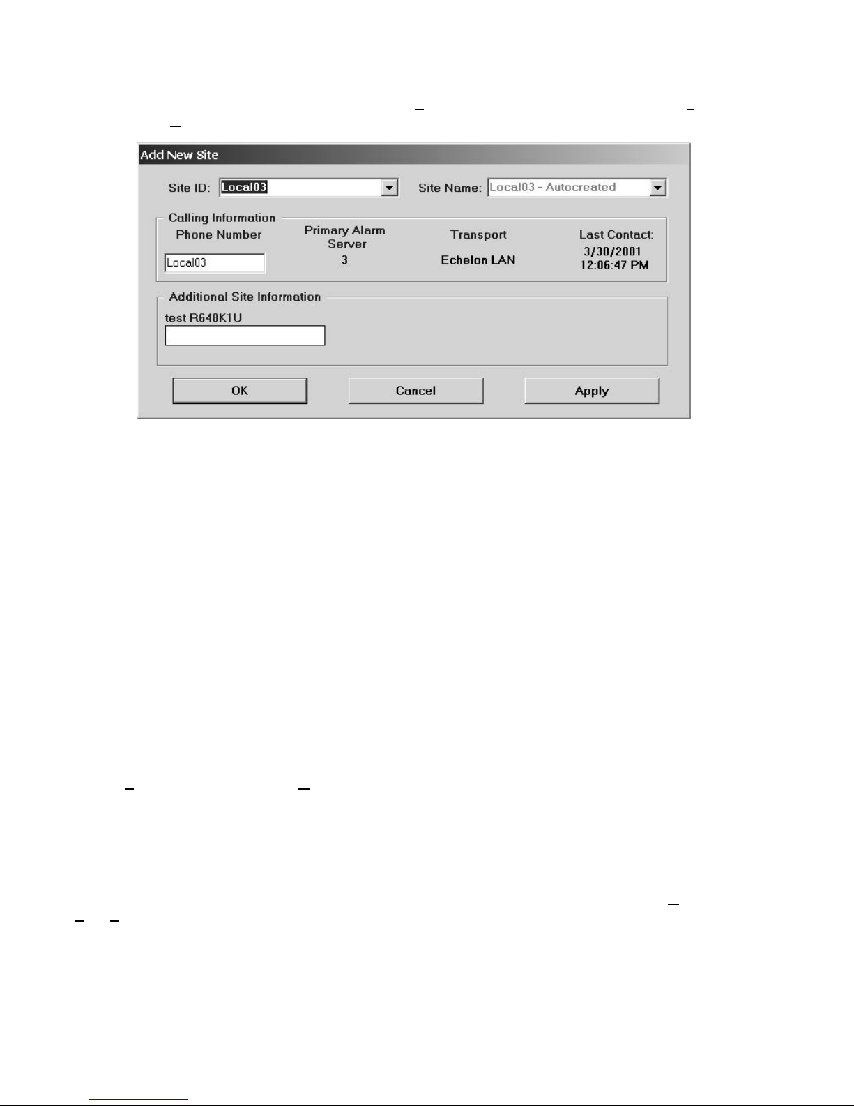
Creating a New Site
To create a new site, go into Graphics mode, then select Create A New Site from the Add/Copy Screen
submenu of the Graphics pulldown on the main screen. This will open the Add New Site form (see figure
below).
Figure 3-9: Add New Site Form
This form is used to enter the initial data about the location both physically and logically of the new site. The New
Site button at the top of the form clears the form of any information. Follow these steps for adding a new site to
the UniNet network:
• Click on the Site ID text box (clicking on the down arrow opens a list box of existing sites). If the new site
is based on a local area network server, enter the naming convention Local##, where ## is the server
number from 1 to 10. If the site is a remote site, any sequence of 15 or fewer characters will work to
identify the site.
• Select the Site Name text box (once again the list box contains existing site names). The Site Name
box holds the "real world" description of the site. Enter a description of the site here.
• The next section is the Calling Information section. This area holds information pertaining to outbound
calls to remote BCI locations. If the new site to be created is a local site, skip this section. Otherwise,
enter the phone number of the modem for the remote BCI in the Phone Number text box.
The Primary Alarm Server field will be automatically configured when the first event comes into the
system. The Transport and Last Contact fields are updated automatically by the workstation.
• The Additional Information box contains custom definable fields that hold non-system-vital
information about the site. These fields are defined on the Site Information Setup page of the
System Administration, Options, System Setup tab form. Additional Information fields can
contain information such as contact names and numbers for a site, mailing addresses, or any other
general information.
• Once all data has been entered properly and verified, click Apply to save the information and OK to
close the form. If you would like to cancel the creation of the new site, click Cancel.
Editing a Site
The information for a site can also be edited at any point after it has been created. To do this, select Graphics,
Edit, Site Information. This will open the same dialog box used to add a new site. Simply edit the desired
information and again, click Apply and OK.
74
The Workstation Installation/Operation Manual Version 2 Document 51540 Rev. B1 4/8/02
Page 75
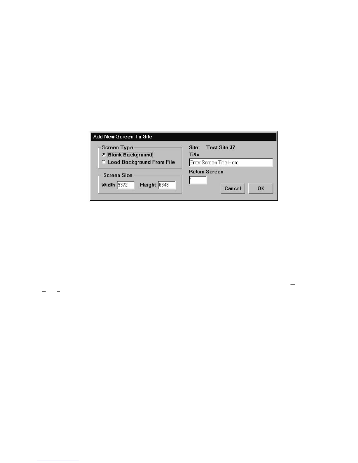
3.2.3 Adding and Editing Screens
Screens are the fundamental visual interface between sites and the operator. Screens are displayed in the Floor
Plan Area of the main display. Each site can contain numerous screens, and screens can contain floor plans,
graphics, and/or devices.
When a site is created automatically, a screen titled Autocreated is made by default. If the site is manually created,
the user is prompted to enter a site name. This screen has a standard layout and contains all devices that have
been detected on that particular site. This screen can be edited to fit the needs of the system, or it can be deleted
and a new screen can be created.
Adding a New Screen to a Site
To add a new screen to a site first select Add A New Screen to this Site in the Add Screen, Graphics
portion of the main screen pull down menu. This will open the Add New Screen to Site form (see figure
below).
Figure 3-10: Add New Screen to Site Form
This form gives the initial settings for the new screen. Follow these procedures for entering this information:
• The Screen Type section allows selection of either starting with a blank background (upon which vector
graphics can be added) or starting with a loaded background. The workstation can load files of type
.BMP and .WMF. BMP is used for background bitmapped images and .WMF is generally used for vector
based floor plan drawings. Select the screen type desired for the new screen. Background images affect
screen loading times, so smaller files work better.
Editing a Site
The information for a site can also be edited at any point after it has been created. To do this, select Graphics,
Edit, Site Information. This will open the same dialog box used to add a new site. Simply edit the desired
information and again, click Apply and OK.
• The Screen Size section contains the dimensions of the new screen in logical units. The default value for
these fields is 9372 x 6348. This value of logical units is roughly one full screen display at full view in the
floor plan display. These values can be modified or left at their default value. Regardless of the dimensions
used, the floor plan display will still show the full screen when it is in full view mode.
• The Site field contains the name of the site for which the new screen will be added. Below the Site field is
the Title field. Enter the name of the new screen to be created in the Title text box.
• The Return Screen box contains the screen number that the system will return to when a bitmap based
keymap is clicked on with the mouse.
• Once the information has been entered and verified, click OK to confirm the addition of the new screen
or Cancel to abort.
If Load Background from File is selected, a file selection window will now open, allowing selection of the
bitmap or vector drawing to use as the background. Select a file of the appropriate type and select OK. The
selected file is copied into the screen database, therefore the original source file does not need to be preserved in
any way.
The Workstation Installation/Operation Manual Version 2 Document 51540 Rev. B1 4/8/02
75
Page 76

If a .WMF vector drawing is used, it will be stored in the workstation's screen database. This format provides an
image that can be re-sized and zoomed without loss of quality and resolution. Individual elements of the vector
drawing can also be edited and the colors modified. For more information on these operations, refer to the section
titled Graphic Tools, which covers the graphic editing of screens.
When zooming, selecting FULL shows everything present on the screen regardless of scale, size or aspect ratio.
Selecting 100% will display all objects at a one to one resolution as they were assigned and placed on the screen.
This means that at 100% backgrounds with aspect ratios that do not match that of the display area will extend
beyond that area. Scroll bars will appear just as they do at higher zoom levels.
3.2.4 Other Screen and Site Related Operations
Copy This Site to A New Site
This option allows copying of the existing screens and settings for a site to a new site. This option is found at
Graphics, Add Screen, Copy This Site to A New Site. When this menu item is selected, the workstation will
copy all the information and screens for the currently displayed screen and its associated site to a new site. A
dialog box will appear and prompt for a new site ID and a new associated phone number. This information is
needed to differentiate between the original and new sites.
Edit Screen Title
This option allows renaming of the currently displayed screen. The software will prompt for a new screen title. This
option is useful for renaming screens that were Auto-created and still have their default titles. This option can be
found at Graphics, Edit, Screen Title.
Delete Screen
This option deletes the currently displayed screen and is found at Graphics, Delete, Screen. When this option
is selected the software will prompt to confirm the deletion of the current screen. Clicking OK will delete the
current screen, while clicking Cancel will abort the delete procedure.
Keep in mind that because of the way information is stored in the screen database, deleting a screen will not
immediately reduce the size of the screen database. In order to free the space again, the screen database must be
compacted. This is done by selecting Compact Screen Database in the Maintenance, Database
Utilities, Compacting menu. For more information on compacting databases and database management, refer
to section 3.5.1 titled Database Management in the System Maintenance section of this manual.
Delete Site
This option operates in the same fashion as Delete Screen except that it deletes the site from which the current
screen belongs and all screens from that site. Delete Site is also found in the Graphics, Delete menu.
NOTES ABOUT DELETING SITES AND SCREENS:
Sites and screens containing off-normal devices cannot be deleted until these devices return to
normal or are reset.
When a screen or site is deleted, all related devices are deleted as well. In addition, any
navigational buttons referring to the deleted screen will also be deleted.
When screens are deleted (both individually and with a site) all screens of a higher number are
decremented to fill the gap. Any references to those screens are updated as well.
When a screen or site is deleted, the action is logged to the Messages window.
76
The Workstation Installation/Operation Manual Version 2 Document 51540 Rev. B1 4/8/02
Page 77
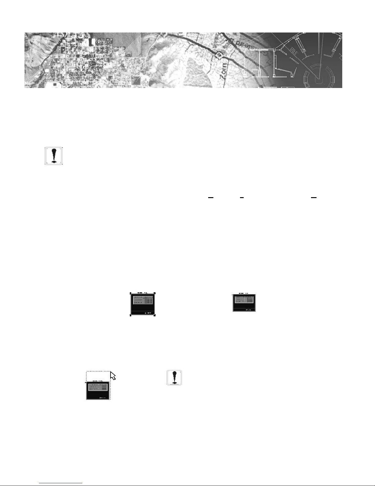
3.3
Section 3.3: Graphic and Screen Editing Tools
3.3.1 Editing Screens
A NOTE ABOUT EDITING SCREENS: Whenever you are editing a screen or site, it is recommended that
you first back up the SCREEN.MDB file. In the event of a mistake, you can revert to the old screen.
Edit Mode
You must activate Edit Mode in order to edit screens, and you must have access to this feature. To activate edit
mode, click on the Edit Screen button in the toolbox or go to Graphics, Edit, Screen Edit Mode On.
To prevent inconsistencies in different workstation databases, only one workstation can edit the databases at a time.
Because activating Edit Mode puts the machine in continual control of editing the database, the computer first
makes a check to see if anyone else is editing in the database. If not, Edit Mode is activated and no other
workstation on the network can perform any editing functions until the user is finished.
Selecting, Moving, and Resizing Objects
Before you can modify, size, move, or edit any objects on the screen, they must be selected. To select an object you
simply click on the middle of the object with the pointer tool. When you hold down the SHIFT key and select
another object it will be selected as well, allowing you to select multiple objects at once. When an object is
selected, four handles appear on the corners around the object. These handles are used to re-size and move an
object.
When you click and hold on a handle with the pointer, a dotted line appears in a box around the object. This box
can now be freely resized. When you release the mouse button, the object will be resized to fill the box. If you
hold down the SHIFT key while resizing an object, the object will maintain proper proportion.
Resizing An Object
Clicking and holding on the middle of the object allows you to move it around the screen without resizing it.
Release the mouse button to replace the object.
The Workstation Installation/Operation Manual Version 2 Document 51540 Rev. B1 4/8/02
Selected
Object
Unselected
Object
NOTE: Text objects have different characteristics than bitmap or vector graphics. For more
information on working with text objects, refer
to section 3.3.4.
77
Page 78
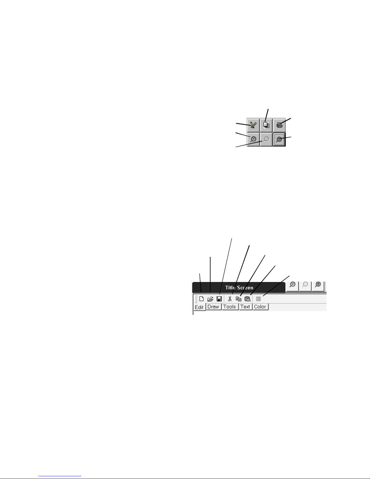
3.3.2 Graphics Toolbox
Toolbox Layout
The graphics toolbox contains buttons for most of the common screen editing tools. These tools are grouped on
separate tabs of the toolbox. The diagram below illustrates what each icon represents. This toolbox is opened and
closed by toggling edit mode from the Common Screen Tools area. For the rest of the section, buttons will be
referred to only by name. Please refer back to this figure as a reference to locate them.
Common Screen Tools
• Edit Mode - Toggles Edit Mode on and off.
• Display Keymap - Displays the keymap
overview window. This button also works when not
in edit mode.
• Print Screen - Prints the floor plan display to the
currently selected printer.
• Zoom In - Increases the zoom of the floor plan
display by 50% (ranges from 100% to 3700%).
• Zoom Out - Decreases the zoom of the floor plan
display by 50% (ranges from 100% to 3700%).
• Zoom Full - Sets the floor plan zoom to full zoom.
Edit Tab
• Add Screen - Adds a new screen to the current
site. Opens the Add Screen dialog (refer to section
3.2.3 Adding and Editing Screens).
• Load Background - Allows replacement of the
current background with a new background (.wmf
or .bmp format).
• Save Floor plan - Saves the floor plan to the
database (updates database of current changes).
• Cut Object - Cuts the currently selected
object(s).
• Copy Object - Copies the currently selected
object(s).
• Paste Object - Pastes previously cut or copied
object(s) onto the current screen. If the cut or
copied object was a device, the software will
prompt for a new device ID and name (see
subsection titled Cutting, Copying, and Pasting).
• Grid Display - Displays an alignment grid on
the floor plan. When selected, opens a numeric
field for the operator to enter a grid size.
Display Keymap
Edit Mode On/Off
Zoom In
Zoom Out
Print Screen
Zoom 100%
Figure 3-11: Common Screen Tools
Save Floor plan
Load
Background
Add
Screen
Cut Object
Copy Object
Paste Object
Grid Display
Figure 3-12: Edit Tab
78
The Workstation Installation/Operation Manual Version 2 Document 51540 Rev. B1 4/8/02
Page 79
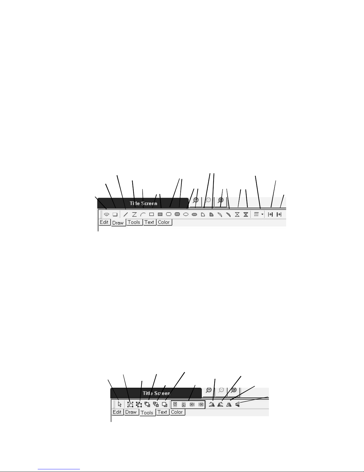
Draw Tab
• Add Device - Adds a new device to the
floor plan display (for information on device
placement and configuration, see Section
3.4).
• Add Button - Adds a button to the floor
plan display (see Section 3.4).
• Add Line - Activates the Line tool (See the
subsection titled Vector Drawing).
• Add Polyline - Activates the Polyline tool
(See the subsection titled Vector Drawing).
• Add Arc - Activates the Arc tool (See the
subsection titled Vector Drawing).
• Add Square - Activates the Box tool (See
the subsection titled Vector Drawing).
• Add Rounded Rectangle - Activates the
Rounded Rectangle tool (See the subsection
Add Line
Add Button
Add Device
Add
Polyline
Add Arc
Add Square
Add Rounded
Rectangle
titled Vector Drawing).
• Add Ellipse - Activates the Ellipse tool (See
the subsection titled Vector Drawing).
• Add Sector - Activates the Sector tool (See the
subsection titled Vector Drawing).
• Add Chord - Activates the Chord tool (See the
subsection titled Vector Drawing).
• Add Polygon - Activates the Polygon tool (See
the subsection titled Vector Drawing).
• Line Style - Select a desired line style for
drawing objects from the Line Style combo box.
• Increase Line Weight - Increments the weight
of a selected object's outline each time it is
clicked.
• Decrease Line Weight - Decrements the
weight of a selected object's outline each time it is
clicked.
Add
Ellipse
Add Sector
Add
Chord
Line Style
Add
Polygon
Increase
Line Weight
Decrease
Line Weight
Figure 3-13: Draw Tab
Tools Tab
• Pointer Tool - Sets the mouse pointer to the
standard arrow pointer for selecting, moving,
and resizing objects.
• Group - Combines a selection of objects into
a single group.
• Ungroup - Explodes a selection of grouped
objects into their individual units.
• Bring to Front - Moves selected objects to
the top layer on the screen.
• Send to Back - Moves selected objects to the
bottom layer of the screen.
• Bring Forward - Moves selected objects up
one layer each time it is clicked.
• Nudge Buttons - Moves selected object in a
Pointer Tool
Group
Ungroup
Bring to
Front
Send to
Back
Bring
Forward
Nudge
Buttons
straight line the desired direction each time the
button is clicked.
• Rotate Clockwise - Rotates selected object
clockwise 90° each time it is clicked.
• Rotate Counter-clockwise - Rotates selected
object counter-clockwise 90° each time it is
clicked.
• Flip Vertical - Transforms the selected object to
a vertical mirror image.
• Flip Horizontal - Transforms the selected
object to a horizontal mirror image.
Rotate
Clockwise
Rotate Counterclockwise
Flip
Vertical
Flip
Horizontal
The Workstation Installation/Operation Manual Version 2 Document 51540 Rev. B1 4/8/02
Figure 3-14: Tools Tab
79
Page 80

Text Tab
For details, see the subsection titled Using Text.
• Font - Select the desired font from the Font
combo box.
• Point Size - Enter a point size for selected text
objects.
• Add Text - Activates the text tool.
• Toggle Bold - Toggles bold for the currently
selected text.
• Toggle Italics - Toggles italics on and off for
the currently selected text.
• Toggle Underline - Toggles underline on
and off for the currently selected text.
• Rotate Clockwise - Rotates selected text
clockwise 5° each time it is clicked.
• Rotate Counter-clockwise - Rotates
selected text counter-clockwise 5° each time it is
clicked.
Font
Toggle Bold
Point Size
Add Text
Toggle
Italics
Toggle
Underline
Rotate
Clockwise
Rotate Counterclockwise
Figure 3-15: Text Tab
NOTE: Only select true type fonts (file extension .ttf), or keymaps will not
work properly.
Color Tab
• Color Palette - Click on a desired color to fill a selected object. Hold the CTRL key and click on a
color to change the outline of the selected object.
Color Palette
80
The Workstation Installation/Operation Manual Version 2 Document 51540 Rev. B1 4/8/02
Figure 3-16: Color Tab
Page 81

3.3.3 Vector Drawing Tools
The UniNet workstation software includes a number of tools for creating vector based graphics on the floor plan
display. All of these tools are accessed through the Graphics Toolbox (explained above), and operate only while in
Edit Mode.
What are Vector Graphics?
Vector graphics are based on lines, boxes, curves, and fills between discrete points in two dimensional space.
Because all objects are described as sets of points, lines, curves, and fills that can be recreated at any scale, vector
drawings are freely scalable over an unlimited range with no loss of resolution. This makes vector drawings ideal
for floor plan layouts and detailed design work.
Vector drawings are also unique in that all the elements always remain independent and can be stacked on top of
each other. The workstation floor plan keeps track of the layering of vector objects, allowing objects to reside
partially over one another without affecting either object. Bitmaps also retain some vector properties when working
with the workstation floor plan. Bitmaps can be moved up and down in the layers, so that vector elements can be
put above or below the bitmap. Bitmaps operate as a vector based box with a bitmap fill.
To move vector objects up or down layers, use the ALT + and ALT - keys. An object can also be brought to the
front of the screen by pressing CTRL-ALT + and an object can be sent to the back layer with the CTRL-ALT - keys.
These key commands will affect all the currently selected objects.
The Mouse Pointer Tools
As different tools are selected for usage in a vector drawing, the mouse pointer will change to reflect the tool.
These tools, referred to here as mouse pointer tools, are all designed to create or modify elements of the vector
drawing. Some of the pointer tools include:
ARROW POINTER LINE
TOOL
ARC TOOL
BOX TOOL ELLIPSE TOOL
Figure 3-17: Mouse Pointer Tools
Since the arrow pointer and its usage has been previously discussed, we will continue here with the other tools
(except the text tool, which is covered in the subsection Using Text). Each time a tool is used, it will return to the
arrow function once the object is drawn. To create multiple objects with the same tool, hold the CTRL key when
selecting the tool and creating the objects. Right clicking any object that has been created with these tools will
open a pop-up menu containing all editing options from the tool bar available for that object.
The Workstation Installation/Operation Manual Version 2 Document 51540 Rev. B1 4/8/02
81
Page 82

The Line Tool
The line tool is one of the most fundamental tools in vector drawing. Its operation is simple:
• Select the Line Tool by clicking on the line tool icon on the toolbar. The mouse pointer will change to the
line tool pointer.
• Click with the left mouse button on the floor plan where you want the first point of the line to start. Hold
down the mouse button and move the pointer to where you would like the line endpoint. Once you
release the mouse button, the software will create a line between the two points defined.
• Keep in mind that once you define one line with the line tool, the software will automatically switch back
to the arrow pointer. If you need to put down multiple lines, you will need to re-select the line tool each
time.
• The color of the line will be the last used default color. To reset the color of a new (or old) line, select the
line to modify with the arrow pointer, and then click the color for the line in the color palette on the Color
tab.
• The line width can also be modified using the hot-keys for increase and decrease line width (CTRL + and
CTRL - respectively). Keep in mind that depending on the size of the floor plan and the current zoom level,
changes in line width may not be immediately apparent.
• The line style can also be modified. There are five different line styles, one solid line and four dotted or
dashed lines. To change the line style, press CTRL * to rotate between available styles. Keep in mind that
CTRL * is not CTRL 8, but uses the * on the num-lock keypad.
The Polyline Tool
The Polyline Tool works in the same manner as the Line Tool except as the line is being drawn it will precisely follow
the path of the mouse pointer on the screen. All features described above also apply.
Arc Tool
The Arc Tool works in essentially the same manner as the line tool except that an arc is used between the start and
end points. As the endpoint of the arc is moved on the floor plan, a dashed line will display the current arc. Once
the appropriate endpoint is located, releasing the mouse button will create the arc.
Once the arc is created, its width can be changed, the line style can be changed, it can be moved, and resized in
the same fashion as a line. You can also modify the color of an arc in the same fashion as you would a line.
Box Tool
The Box Tool works under the basic principle of creating a box based on the start and end points of a diagonal line
through two opposite corners of the box. By clicking and holding to set a start point, and dragging to an endpoint,
you can create a rectangular box of any dimensions. As the endpoint is moved on the floor plan, a dashed box is
displayed to show the box as it would exist based on the current endpoint.
When drawing a box, holding down the SHIFT key causes the software to force the line to a 45 degree angle,
creating a square with equal sides instead of a rectangle. Moving the endpoint of the square will change only its
size.
By default, the Box Tool creates a non-filled box that consists only of the lines that compose the four sides of the
box. The fill portion of the box is transparent and any objects underneath the box will be visible. The line width
can be modified in the same fashion as a line. You can modify the fill style of a box by pressing CTRL F while the
box is selected. Using this, you can change a non-filled box into a filled box and vice-versa. You can also scroll
through a number of hatching fill patterns for boxes with the CTRL F key.
In order to change the outline color of a box, you must hold down the CTRL key when selecting the color in the
color palette. Pressing a color without holding down CTRL modifies the FILL color of the box, but has no effect if
the box is set to transparent.
You can also change the outline style of the box using CTRL * in the same fashion as with a single line. Keep in
mind that CTRL * is not CTRL 8, but uses the * on the num-lock keypad.
82
The Workstation Installation/Operation Manual Version 2 Document 51540 Rev. B1 4/8/02
Page 83

Filled Box Tool
This tool works in the exact same fashion as the box tool except that instead of a transparent fill, it has a solid color
fill by default. Everything works in the same way as the box tool. When working with a filled object (box ellipse,
sector, chord or polygon), selecting the box and then a color on the color palette will modify the fill color of the
box. To change the outline color of the box, hold down the CTRL key and select a color on the color palette.
You can change the fill style of a 'filled' box by pressing CTRL F. The options for fill style are solid color,
transparent, and six different hatching styles.
Rounded Rectangle and Filled Rounded Rectangle Tool
These tools work in exactly the same fashion as the Box tools except that the objects created have radiused corners.
The shape of the corners is defined by the aspect the rectangle. A square will have corners that are a perfect radius
while high aspect ratio rectangles will have corners that appear to be squashed.
Ellipse Tool and Filled Ellipse Tool
The Ellipse Tool (filled and non-filled) creates an ellipse on the basic principle of imposing an ellipse inside of the
box created by start and end points of a diagonal line. As with the box tool, holding down the SHIFT key while
placing the end point forces a 45 degree line and as a result creates a circle (an ellipse imposed in a square).
Other than their difference in appearance, ellipses operate in the exact same fashion as boxes. Outline width, fill
style, fill color, and outline color can all be changed in the same way as with a box.
Sector Tool and Filled Sector Tool
The Sector Tool works similarly to the Arc Tool except that it creates a closed pie slice object. When the endpoints
are defined a dashed line will display an arc on one side and two lines projected on the other which meet at a
right angle. All other characteristics are the same as those described for other closed and filled objects.
Chord Tool and Filled Chord Tool
The Chord Tool works in exactly the same fashion as the Sector Tool except that instead of creating two straight
lines that meet at right angles for a pie shape, it draws a single straight line between the endpoints of the arc. All
other characteristics are the same as those described for other closed and filled objects.
Polygon Tool and Filled Polygon Tool
The Polygon Tool is based on the Polyline Tool. It functions in the same manner as the Polyline Tool except that it
creates a closed object by connecting the two endpoints of the Polyline with a straight line. All other characteristics
are the same as those described for other closed and filled objects.
A NOTE ON PATTERN FILLS: The pattern for a pattern fill does not resize
with various zoom levels because of the way the fill operates. Keep this
in mind when creating smaller objects with fills because at high zoom
levels, the fill may not appear the same or even be visible.
The Workstation Installation/Operation Manual Version 2 Document 51540 Rev. B1 4/8/02
83
Page 84

3.3.4 Using Text
Text in the workstation can take two fundamental forms:
• device text
• non device text
Device text is defined as text labels that relate to specific devices and their icons. Device text is covered in the
Devices section of the manual. Non-device text is text that has no functional usage other than to label and title
screens and objects in the workstation.
Non-device text is created using the text tool from the tool bar. Select the desired font, size and formating features
for the text to be created. Select the T button to get the text cursor and click on the screen where the text is to be
placed. A text dialog box will open (displayed above). Enter the desired text there and click the OK button. The
text will be placed on the screen.
Once text is placed, it can be moved like other objects. It can be resized by changing the value in the Point Size
field on the Text Tab. Text which has already been placed can be edited by selecting it with the pointer tool, right
clicking and selecting Edit Text from the menu. A cursor will appear at the end of the text line and the text can be
modified.
Different fonts can be selected for text using the Font combo box on the Text tab. Any installed font in Windows
may be used.
NOTE: Only true type fonts (file extension .ttf) are
recommended for use. Other font types are not correctly sized
in the keymap.
The color of text can also be modified. To change the color of text on the floor plan, simply select the text and then
click the desired color in the color palette. Text will begin with the currently selected default color.
When typing text or when a line of text is selected by the arrow pointer, the three toggle switches for bold, italics,
and underline will toggle these characteristics for the entire line. The keyboard shortcuts CTRL-ALT B, I, and U also
work for each toggle.
3.3.5 Importing .BMP and .WMF Files
What are .BMP Files?
.BMP is an extension that stands for bitmap. Bitmaps are files that hold basic image data in the form of a grid of
pixels, each with a certain color. Bitmaps are the standard method of importing and transporting image type
information. Bitmap files each have a specific size in pixels. Because of this, they degrade in quality if they are
zoomed or resized.
Importing .BMP Files
There are two different occasions in the creation of a screen when .BMP files can be added. When a screen is first
created (see Section titled Site and Screen Management), the load background option will allow the importation of
a .BMP as a background. Remember when using .BMP files as backgrounds that, when zoomed, they will lose
image quality. At 200% zoom, a bitmap's pixels will appear twice as large as at 100% and therefore have half the
resolution.
.BMP files can also be added to a screen once the screen is created. This is done with the Bitmap option in the
Graphics, Add Symbol menu off of the main screen. Bitmaps import at their resolution in relation to the
current screen size and the current zoom level. Bitmaps added using this method can be resized freely and moved.
Bitmaps can not be rotated.
What are .WMF Files?
.WMF stands for Windows Meta Files. These files hold vector drawing information, discrete points, lines, and
curves. .WMF files are used in the workstation predominately for importing floor plans. Because .WMF files are
vector based, the information in them can be resized without loss of resolution and quality. When dealing with
floor plans in the workstation, this is very important as it allows the floor plan to be zoomed in without degrading
resolution of the lines.
84
The Workstation Installation/Operation Manual Version 2 Document 51540 Rev. B1 4/8/02
Page 85

Importing .WMF files
.WMF files are read into the software and converted into individual lines that can be moved, colorized, resized, and
deleted with the workstation vector drawing tools. A good starting point for screen creation is to import a floor plan
of the building or area that is being monitored. The software will resize the vector based floor plan to full screen
(without loss of resolution), and from there the floor plan can be modified, and icons, buttons and devices can be
added.
Screen Database Storage of Imported Files
Rather than creating a link to the file that has been imported, which leaves the system vulnerable to errors and
problems, the workstation software adds the raw data of a bitmap and the vector format information of a .WMF file
directly to the database. This means that the screen database file will grow more dramatically in size if numerous
.WMF and .BMP files are used. In most cases this is acceptable, but keep in mind that a slightly longer load time
will be required for larger screen database files.
3.3.6 Cutting, Copying and Pasting
The workstation provides three basic features to allow easier transportation and replication of screen elements.
Cutting and Pasting (as a pair) is useful for moving elements from one screen to another screen. Copying and
Pasting (as a pair) is useful for replicating an object or element multiple times on one or more screens.
The functions of copy and cut both use the clipboard to record the information of any currently selected objects. In
addition, cut removes the selected objects from the screen. Pasting causes the objects stored in the clipboard to be
placed on the current screen (even if the current screen is different from the screen the object(s) were copied or cut
from originally).
NOTE: The workstation uses a clipboard and cut/copy/paste format that is not compatible with
windows standard cut/copy/paste clipboard functions. Because of this, it is not possible to paste an
object from another application into the workstation and it is not possible to cut or copy a
workstation element and paste it into another document.
It is possible to cut/copy/paste in two different ways in the workstation. There are toolbar buttons for cut/copy/
paste, and the keyboard shortcuts CTRL X, C, and V are also usable. These keyboard shortcuts are standard (X for
cut, C for Copy and V for Paste) keyboard shortcuts and are included so that users can follow a known convention.
NOTE: Devices in an off-normal state cannot be cut or copied.
3.3.7 Repairing Screens
If for any reason elements of a screen become corrupted, you may not be able to access that screen. When this
happens, the Repair Existing Screen feature can restore undamaged elements, allowing you to recreate only those
graphics which were corrupted. This prevents the user from having to rebuild an entire screen if it becomes corrupted.
To access this feature, select Graphics, Activate Edit Mode. After going into edit mode, select Graphics,
Repair Existing Screen, and the corresponding dialog will appear. Select Screen Number To Repair from
the combo box.
The Workstation Installation/Operation Manual Version 2 Document 51540 Rev. B1 4/8/02
85
Page 86

NOTES
86
The Workstation Installation/Operation Manual Version 2 Document 51540 Rev. B1 4/8/02
Page 87

3.4
Section 3.4: Device Placement and Configuration
3.4.1 Graphic Devices - Description
Graphic devices are the primary event annunciation and user configurable on-screen tools of the workstation. The
user can create an unlimited number of graphic devices and place them on any screen of the workstation. The
workstation even auto-creates devices for new events.
Six device types are available:
• Addressable Discrete Devices.
• Addressable Analog Devices.
• Functional Buttons.
• Navigation Buttons.
• Site Annunciation Icons.
• Information Labels.
Creation and editing of each of these device types is discussed in the following sections.
NOTES: Each node can be configured to annunciate in text mode only. For more information on text
mode, refer to Section 3.5: System Maintenance, Node Configuration. The workstation must be in
Edit Mode to add devices.
Addressable Devices
This category of device represents actual physical devices being monitored by the network like pullstations, card
readers, motion detectors, etc... These devices have an address displayed with the graphic symbol and they
change appearance when an off-normal event is reported for them. In addition, the related text field flashes and
displays the off-normal status (i.e. trouble, alarm). Optionally, files can also be attached to each one containing
text, pictures, sound and video.
Two types of addressable devices are assignable; discrete and analog. Discrete devices report distinct state
changes, while analog devices are configurable to report measured values over a defined range with adjustable
alarm levels.
Buttons
Two types of buttons are available; functional and navigation. Navigation buttons are assigned screen numbers
and provide a point-and-click short cut from one screen to another. Functional buttons work like configurable hotkeys and provide the same point-and-click convenience to execute commands and macros (i.e. acknowledging a
particular node).
NOTE: It is strongly advised that a backup of the
c:\uninet\ws\screen.mdb file be done after any
changes to the devices are made. A backup of the
devices directory and the infolabel directory should be
made any time device or infolabel bitmaps have been
created or edited.
Site Annunciation Icons
Site annunciation icons can be placed in any screen location. When that screen is displayed the site is checked for
any outstanding off-normal events. If the result is true then the icon is displayed in its off-normal condition.
Information Labels
A complete library of graphical warning and Hazmat icons is included. These devices can be placed on any
screen to provide standard universal warnings to screens. In addition, each assigned device can have the same
types of optional files assigned to them as addressable devices.
The Workstation Installation/Operation Manual Version 2 Document 51540 Rev. B1 4/8/02
87
Page 88

3.4.2 Adding Addressable Devices
Addressable devices can be assigned at any time during workstation configuration or they are created automatically the first time a device reports in. All addressable devices are placed on a screen within the site with which
they are associated. Discrete and analog devices are identified by a logical address. This address is made up of
three sections:
• Node number (3 digits).
• Subnode (3 digits).
• Device ID (8 characters).
NOTE: Every addressable device should have a device icon. If field
devices don't have a related icon, one will be created on the first screen
of the related site the first time the device reports an event. Device
icons created in this manner should be edited to ensure all information
is complete and moved to the proper screen they are associated with.
The address is displayed as a text field above the graphic symbol that represents the device.
Node Number - The node number is the number assigned to the NION monitoring the device in the field. Node
numbers are assigned to NIONs either at a local area server or a BCI where they are attached.
Subnode - A subnode number is used when a NION is monitoring another network or a wide area server is
connected to a digital receiver with multiple accounts. Each subnode number represents a node on the other
network or a receiver account number.
Device ID - The device ID is the eight character alphanumeric address for the monitored point reported by the
NION.
Subnode
Node Number
Device ID
Graphic
Symbol
Figure 3-18: Addressable Device
NOTES: The Device ID entered for each device must match the device ID reported by the NION exactly.
For more information on ID formats, refer to documentation supplied with each NION or Echelon network. Devices should be added after the floor plan background has been added to ease device sizing
and placement.
88
The Workstation Installation/Operation Manual Version 2 Document 51540 Rev. B1 4/8/02
Page 89

3.4.3 The New Devices Dialog
When adding an addressable device, first navigate to the screen under the site where the device will be located.
Next, zoom in the floor plan to the level of resolution at which you want the default device size displayed. Then,
select the menu items Graphics, Add Symbol, Device. This opens the New Device dialog with the default
settings shown.
Site
Device Address
Device Alias
Figure 3-19: New Device Dialog
The Workstation Installation/Operation Manual Version 2 Document 51540 Rev. B1 4/8/02
89
Page 90
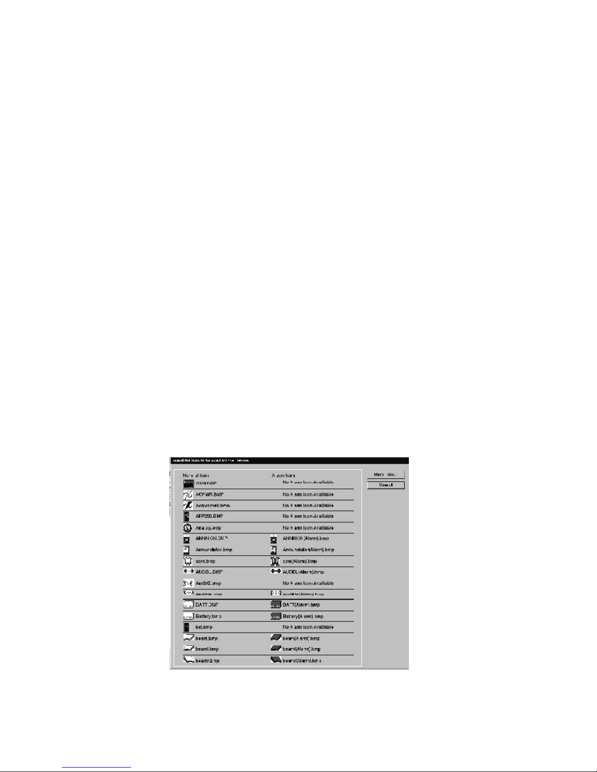
Each section of the New Devices dialog contains input fields and option lists for defining a device. All
parameters of a discrete device can be defined on this form. Analog devices require additional configuration on a
related form. Analog devices are covered in the next section. Each feature of the New Device dialog is
described below.
Device ID
The address of the device, as previously described, is entered here. The node number must be entered as it is
defined at the local area server or BCI where the node is attached. The subnode number (if needed) must match
the number of the node monitored on the other network or the account number assigned in the digital receiver. If
no subnode is needed zeroes will be used. The address field is used to enter the eight character device ID.
Site ID
The Site ID is automatically read from the site in which you are currently working.
Display ID
The display ID is an optional alias address for workstation display. This ID is definable as any logical address
desired up to 14 characters. The operator can toggle between the absolute address and the alias address for
workstation display in the View menu. The pipe (|) character and single quote (') are not valid and are automatically removed from any entries.
Autonavigate
The autonavigate option determines whether the screen containing the device appears automatically during an offnormal event.
Discrete / Analog
This option defines the device as discrete or analog. Analog devices require additional configuration. For more
information on defining analog devices, refer to the next section.
Symbol
This area displays the graphic symbol selected for device display. To select a new symbol click on one of current
symbols. This brings up the Device Library. Click on the desired device for display. Most devices have two
symbols, one for normal status and one for off-normal status. Selecting one symbol of the pair automatically selects
both.
Figure 3-20: The Device Library
90
The Workstation Installation/Operation Manual Version 2 Document 51540 Rev. B1 4/8/02
Page 91

Additional Device Information
Device types relate to the precise nature of the device being monitored. They define the device as a photoelectric
smoke detector, a manual pullstation, a card reader, a motion detector, etc... This assignment is done automatically if the device is autocreated.
There are also two optional assignments; category and subcategory. These assignments are entirely at the discretion of the administrator and are provided as logical definition tools. Once these categories are defined, they can
be used in the creation of Plug-in Application Macros. For more information on Plug-in Applications and related
macros, refer to the section 3.5.4 System Maintenance: Macro Editor.
Device Description
A description for the device can be entered here or extracted from the monitored device (if the device provides
descriptions). Which mode the workstation uses must be selected by the administrator. For more information, refer
to the section Other Device Features.
Linked Files
This option allows four different file types to be linked with a device:
• Text files (.txt).
• Bitmaps (.bmp).
• Sound files (.wav).
NOTE: Devices with linked files are indicated in the
display by an asterisk next to the graphic symbol, in
the upper left corner.
• Video (.avi).
When any of these file types are linked to a device they can be displayed or activated by the operator by selecting
them from the device pop-up menu. In addition, each of these files can be set to be automatically activated when
the device reports an off-normal event. All available files can be selected from the associated combo box. For
more information on creating and managing these files, refer to the section Adding Sound, Video and Text.
3.4.4 Defining Analog Devices
Analog devices are similar to Discrete devices in that they use graphical symbols and text to annunciate off-normal
conditions. However, discrete devices only annunciate a small number of distinct state changes whereas analog
devices can report a range of measured values for devices with adjustable alarm set points.
To define an analog device follow the same steps for defining a discrete device with the following exception: In the
Discrete / Analog area of the New Device dialog select Analog then press the Configure button. This
opens the Analog Input Device dialog.
Device Assignment Area
Device Testing Area
Figure 3-21: Analog Input Device Dialog
The Workstation Installation/Operation Manual Version 2 Document 51540 Rev. B1 4/8/02
91
Page 92
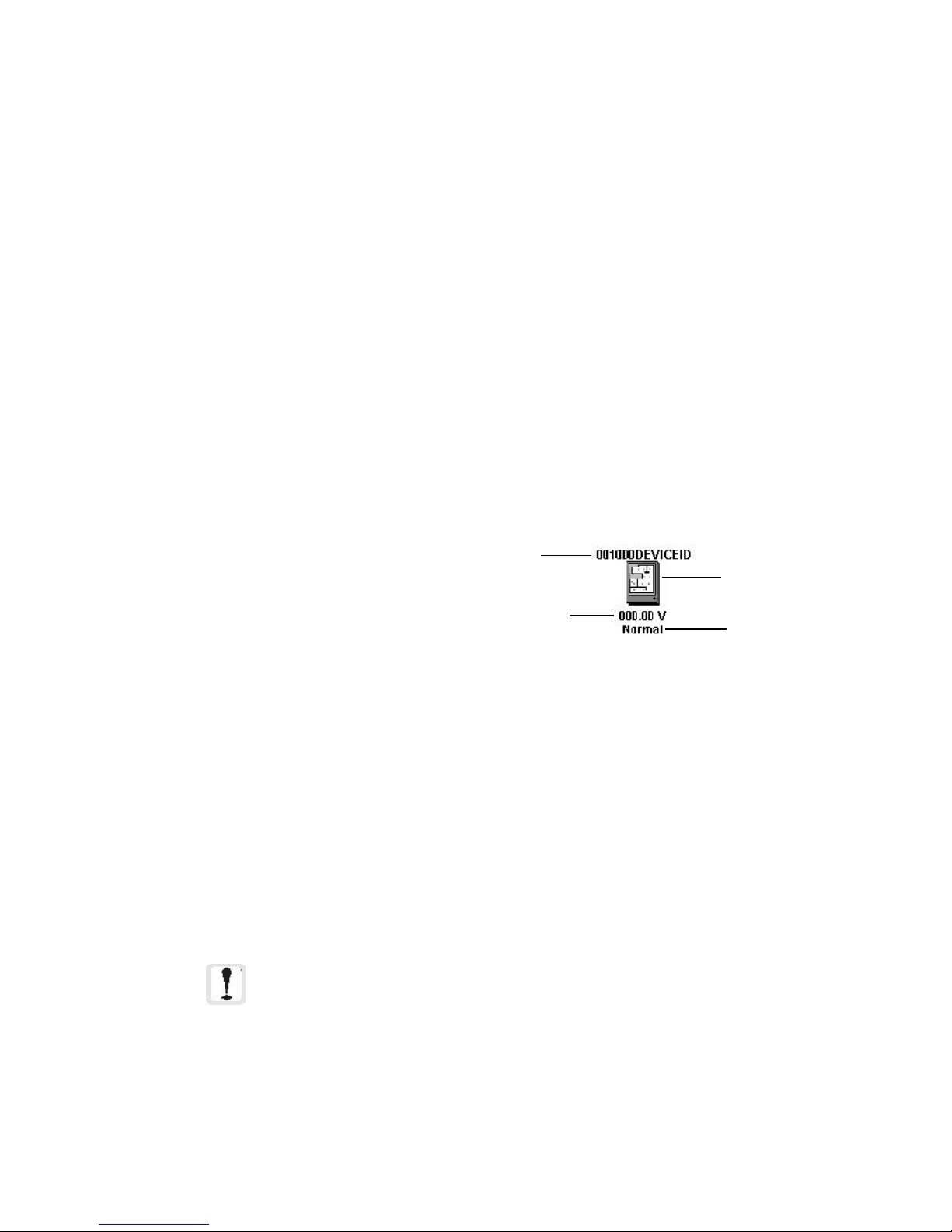
The Analog Input Device dialog is divided into two areas, the Device Assignment Area and the Device
Testing Area. The display style and performance of the device are defined in the assignment area. Then, its
performance can be manually demonstrated in the testing area to verify expected performance before finishing the
assignment.
Device Assignment Area
The device assignment area allows the definition of three basic parameters:
• Range Translation.
• Alarm Thresholds.
• Report Frequency.
Range Translation - The analog device configuration form allows configuration of a range translation
between what is reported by the analog device and what is annunciated and interpreted by the workstation. The
translation portion of the form shows the native values and units. Below this, a space is provided to enter a new
range of values and to specify the new units. The software will automatically perform this translation. All values
displayed in the analog configuration refer to the converted range, not the native range. If a new range is entered
and a threshold point is not within that range, then an error message will be displayed to alert the user of this. In
addition, if a threshold is out of range, it is displayed over a red background instead of a green background.
Alarm Thresholds - These fields allow alarm points to be inserted at different levels in the device's reporting
range. When an analog value is reported for a device it is compared to the assigned alarm thresholds. If the
reported value falls between the first low and first high threshold the device remains in a normal state. As the value
rises and falls it will cause an alarm state in the device when it passes a threshold value. Therefore, reaching the
threshold will not cause a change of state.
Six threshold levels can be assigned:
• Very High.
• Higher.
• High.
• Low.
• Lower.
Address
Symbol
Reported Value
(Adjusted) Device State
Figure 3-22: The Analog Device
• Very Low.
Three parameters must be configured for each alarm threshold:
• Threshold value - This is a numeric value for comparison to the adjusted reporting value. The threshold
can be configured using the blue handles to the side of the threshold scale. Moving these handles within
the range allows quick setting of an alarm point. If a threshold value is out of range, it will be displayed in
a red field instead of a green field.
• Alarm message - Descriptor for the related alarm state. This message is displayed above the device
icon, and is reported as an event when the specified threshold is crossed.
• Device Symbol - Click on the Browse button to open the device library and select a graphic symbol
for each alarm state and the normal condition. Seven must be selected. A variety of device symbols for
gauges and scales in different states are available. Custom symbols can also be created. For more
information on creating custom symbols, refer to the section 3.4.9 Creating Device Symbols.
NOTE: All thresholds must be entered as converted display values and
are compared to reported values after they have been adjusted by the
range translation.
Report Frequency - A Report Frequency is set for both normal and off-normal conditions for each analog
device. These values represent the amount of time in seconds between each update of the current analog value of
the device. Different frequencies can be specified for both off-normal and normal conditions to allow more
frequent reporting during problematic situations.
92
The Workstation Installation/Operation Manual Version 2 Document 51540 Rev. B1 4/8/02
Page 93
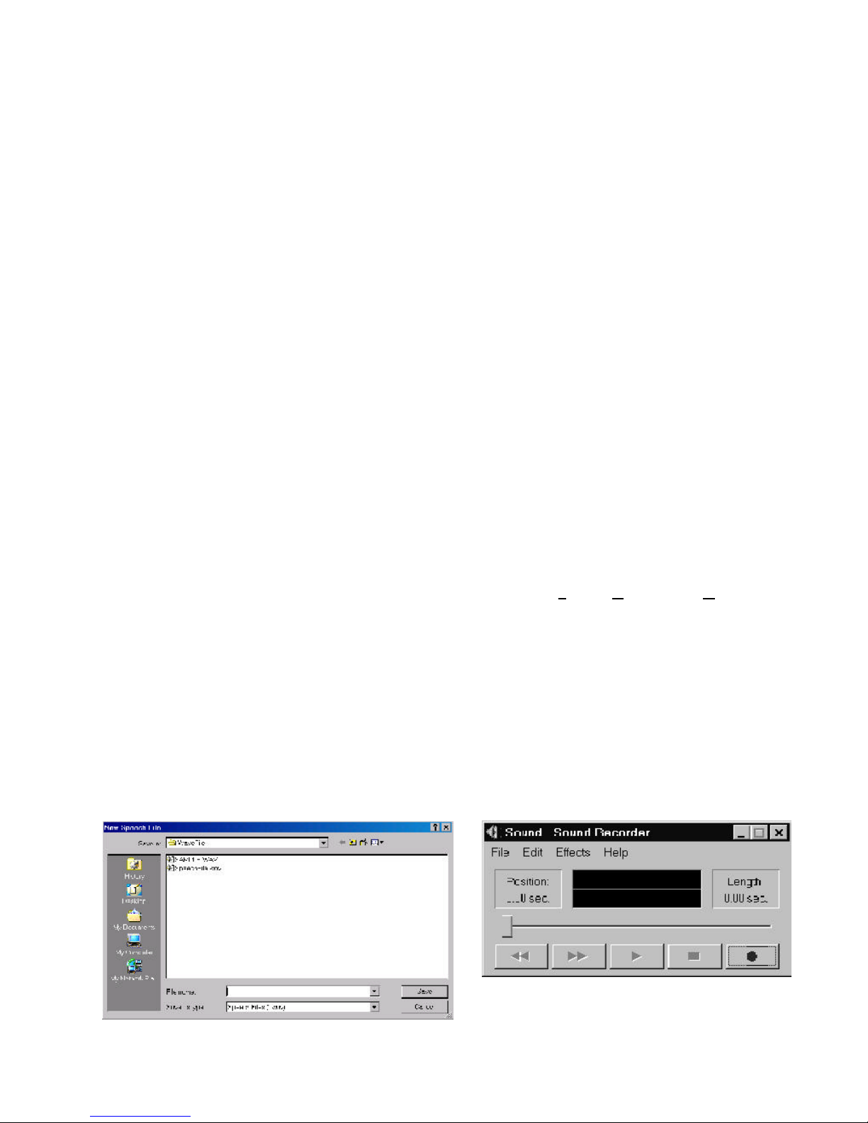
Device Testing Area
The area on the right side of the Analog Input Device dialog provides a simple testing tool to check the performance of a newly assigned analog device. The Sample Display area shows the device graphics with address,
value and state fields. The Value Sweeper has a control handle that can be moved up and down the range. As
it is moved the display values will change and the alarm states will be annunciated as each assigned alarm
threshold is reached. To use the sweeper handle simply click and hold the handle with the mouse pointer and slide
it up and down the range.
3.4.5 Adding Sound, Video and Text
As described earlier, sound, video, text, and pictures can be linked to devices for display and playback. It is up to
the administrator to provide the sources of these files. Video and picture files must be added to the workstation
from outside resources. Speech and text files can be created and maintained using the Workstation utilities provided.
Adding Video and Picture Files
Video files must be in .avi format for playback in the workstation. When copying video files (.avi) to the workstation place them in the c:\uninet\ws\avifile directory. Picture files must be in bitmap format with a .bmp
extension. They should be placed in the c:\uninet\ws\bitmap directory.
Creating Voice Files
There are two types of voice messages in the UniNet system: those that are linked to events and those that are
linked to devices. Files that will be linked to events must be in c:\uninet\ws\lang1 or c:\uninet\ws\lang2.
Files that will be linked to a device must be in c:\uninet\ws\wavefile. In order to record voice files, the Voice
Messaging option must be installed.
For instance, a device goes into alarm. A voice message is assembled using a file assigned in the Speech Annunciation File Assignment dialog in the System Setup folder for the alarm type and files for the device address (e.g.
"Alert: Alarm in node one, device 02D01"). The screen will autonavigate to the device symbol in alarm. If the
device symbol has a red asterisk next to it, click the device symbol with the left mouse button. If Play Audible
Message is in the pop-up menu, there is a voice file linked to the device (e.g. "This detector is next to a
biohazard. Beware!"). This voice file is linked to the device using the Add Symbol, Device under Graphics or
Edit Symbol Attributes in the device's pop-up menu.
Any operator with proper access levels may record new event-linked and device-linked voice files. There is a library
of event-linked voice files provided with UniNet which may be used or edited. Recording and listening to voice files
is done using the Speech Editor. There are two ways to access the Speech Editor in the UniNet software: New/
Open Speech File in the File menu and Assign Voice Annunciation in the System Setup folder (primarily
for event-linked files).
New Speech File:
After selecting New Speech File from the File menu, a window will open, allowing either selection of an existing
file, or creation of a new file. To create a new file, type the name of the file in the File Name field. Once a name
has been designated, select Save the Sound Recorder will appear. If selecting an already existing speech file, a
warning will appear stating that the current file will be overwritten.
The Workstation Installation/Operation Manual Version 2 Document 51540 Rev. B1 4/8/02
Figure 3-23: The Sound Recorder
93
Page 94
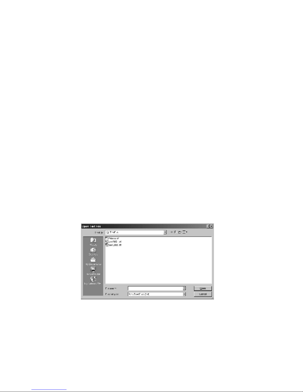
To start recording, press the record button. Speak clearly into the microphone. When finished, press the Stop
button. The length of the file is indicated on the right-hand side of the speech editor. To listen to the voice file,
press the Play button. If the message is correct, select Save File As from the File menu. Enter a name for the
file and make sure the path is correct. Voice files for use with the UniNet system must be saved as *.wav files.
The name and path of the voice message will appear on the bottom of the screen. If the message needs to be
rerecorded, select New from the File menu. To listen to a voice file that already exists, select Open from the File
menu and select the voice file. To exit the Sound Recorder, select Exit from the File menu. For more information
on Sound Recorder, refer to Appendix D.
Assign Voice Annunciation
The Sound Recorder may also be accessed through Speech Annunciation in the System Setup folder. To
access the Sound Recorder, press the New File button. The Sound Recorder will appear. Refer to New/Open
Speech File for more information.
Creating Text Files
Text files are used in the UniNet system to inform operators when there are important messages associated with a
screen or device. Text files are accessed through the pop-up device menu item, View Documentation. These
files must be linked to the device via the New Device Symbol or Edit Device Symbol dialog boxes. The path
to these files must be c:\uninet\ws\textfile.
To create a text file:
Select New Text File from the File menu. The Windows Wordpad will appear. Type in the information. Select
Save As... from the File menu. The Save As dialog will appear. Assign the file a name and make sure it is
saved to c:\uninet\ws\textfile. To exit Wordpad, select Exit from the File menu. The operator may then link
the file to a device.
To open a text file:
Select Open Text File from the File menu. The Open Text File dialog will appear (see figure below).
Figure 3-24: The Open Text File Dialog
Select the text file to be opened. Once selected, press OK to open the file or Cancel to abort.
94
The Workstation Installation/Operation Manual Version 2 Document 51540 Rev. B1 4/8/02
Page 95
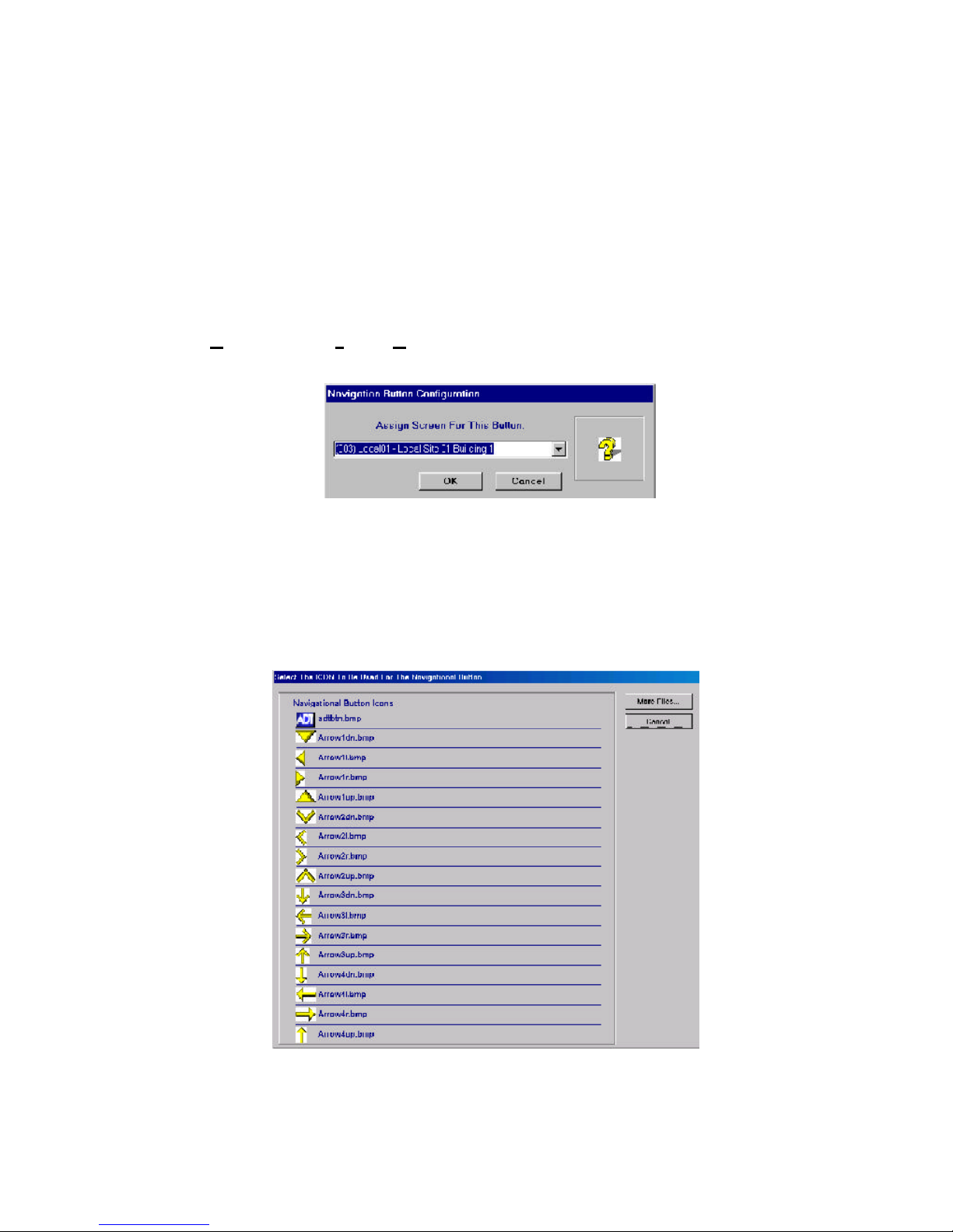
3.4.6 Navigation and Functional Buttons
Two types of button devices can be assigned to screens, Navigation and Functional buttons.
Navigation buttons are linked to other screens and provide navigation shortcuts for operators.
Functional buttons are assigned to predefined macros to provide command shortcuts to operators.
Buttons can be placed on any screen and multiple buttons can access the same screen or execute the same macro.
For more information on defining macros refer to the section 3.5.4 System Maintenance, Macro Editor.
Assigning Navigation Buttons
To assign a navigation button:
1. Go to the screen where the button is to be placed.
2. Select Graphics, Add Symbol, Navigational Button . This opens the Navigation Button dialog.
Figure 3-25: Button Link Dialog
3. Select a screen from the combo box the button is to open when clicked. Next, open the Navigation
Button Library by clicking on the icon area to the right.
Figure 3-26: The Navigation Button Library
The Workstation Installation/Operation Manual Version 2 Document 51540 Rev. B1 4/8/02
95
Page 96

4. Select a graphic symbol for the button.
5. Place the button in the desired screen location.
Assigning Functional Buttons
To assign a functional button:
1. Go to the screen where the button is to be placed.
2. Select Graphics, Add Symbol, Functional Button. This opens the Functional Button Configu-
ration dialog.
Figure 3-27: Functional Button Configuration Dialog
3. Enter the number of the macro to be executed when the button is clicked. Next, open the Functional
Button Library by clicking on the icon area to the right.
Figure 3-28: The Functional Button Library
4. Select a graphic symbol for the button.
5. Place the button in the desired screen location.
96
The Workstation Installation/Operation Manual Version 2 Document 51540 Rev. B1 4/8/02
Page 97

3.4.7 Annunciation Icons
Annunciation icons are two state devices that represent current conditions for an entire site. When an annunciation
icon is assigned for a site it displays a normal condition when the site is completely free of off-normal devices. If
any one device goes to an off-normal state then the icon displays the site as off-normal. These devices can be
placed on any screen or on any site. They do not autonavigate.
To assign an annunciation icon:
1. Go to the screen where the icon is to be placed.
2. Select Graphics, Add Symbol, Site Symbol. This opens the Site Annunciation Label dialog.
NOTE: For more information on building macros, refer to section 3.5.4.
Figure 3-29: Site Link Dialog
3. Enter the site number for the icon. Next, open the Site Symbol Library by clicking on one of the icon
boxes to the right.
Figure 3-30: The Site Symbol Library
4. Select a pair of graphic symbols for the icon.
5. Place the icon in the desired screen location.
The Workstation Installation/Operation Manual Version 2 Document 51540 Rev. B1 4/8/02
97
Page 98

3.4.8 Information Labels
Information labels are graphic devices that provide additional important information about a location represented
on a screen. These labels are generally common symbols and warning signs (i.e. flammable, poison, biohazard,
etc.). Information labels do not receive information regarding alarms and troubles from the system. They can have
video, picture, text and sound files linked to them to provide additional information just like addressable devices.
To add an information label:
1. Go to the screen where the label is to be placed.
2. Select Graphics, Add Symbol, Information Label. This opens the Information Label Link dialog.
NOTE: Devices with linked files are indicated by an asterisk next to the graphic symbol.
Figure 3-31: Information Label Link Dialog
NOTE: All linked files must be stored on the same computer as the workstation application in the
default directory initially displayed in the dialog.
3. Select sound, text, picture and video files by clicking the related check box and using the Browse buttons
to locate the desired files. Next, click on the device symbol area on the left. This opens the Information
Label Library.
Figure 3-32: The Information Label Library
4. Select a graphic symbol for the label and click the OK button.
5. Place the label in the desired screen location.
98
The Workstation Installation/Operation Manual Version 2 Document 51540 Rev. B1 4/8/02
Page 99

3.4.9 Creating a Device Symbol
UniNet includes a comprehensive library of
device symbols, however custom symbols may
be created by the user for library inclusion.
These symbols must be created off-line using
any graphic design package or imported from
another source and saved in bitmap (.bmp)
format. This description uses Windows Paint.
To create a new device symbol:
1. Launch Paint from the Start,
Programs, Accessories menu in
Windows.
2. Using Paint, draw the new device
symbol. The symbol size should be
approximately 53 pixels by 53 pixels.
3. When finished, use the selection tool
to draw a box closely encompassing
the device (see figure 3-33).
4. With the device selected, select Copy
To... from the Edit menu. This
opens the Copy To dialog.
5. Save the file as a 16-color bitmap with a unique logical name.
Selection Box
Selection Tool
Figure 3-33: Using the
Selection Tool to Create a
Box
Be sure to save the file to the c:\uninet\ws\devices directory.
Normal and Alarm State Symbols
Addressable devices have the ability to change state during an off-normal event. This means that the symbol
changes from a normal state to an alarm state. This requires two symbols assigned to the same device, one for the
normal state and one for the alarm state. Dual state device symbols for addressable devices are optional. They are
required only if you wish the device's appearance to change during an off-normal event.
To create an alarm state symbol to pair with a newly created normal symbol:
1. Open the normal device symbol in Paint.
2. Make changes to reflect the alarm state appearance.
3. Select File, Save As... and save the new version with the same name but, with (Alarm) at the end of
the name.
Example: Normal symbol file name = bell.bmp Alarm symbol file name = bell(Alarm).bmp
Be sure to save the file to the c:\uninet\ws\devices directory.
Device Masks
Device masks are layering tools which allow the background of a device symbol to be transparent so that it doesn't
block the floor plan.
To create a mask for the new device symbol:
1. Open the new device symbol in Paint.
2. Fill the object with black and leave the white background.
3. Select File, Save As... and save the new version with the same name but with a .msk extension.
Be sure to save the file to the c:\uninet\ws\devices directory. This must be done for the normal state symbol
and the alarm state symbol.
The Workstation Installation/Operation Manual Version 2 Document 51540 Rev. B1 4/8/02
99
Page 100

3.4.10 Other Device Features
Search for a Device
A device search utility is provided to locate an addressable device anywhere on the workstation. When used it
changes to the screen where the device is located. To execute a device search, select Graphics, Search for a
Symbol. Then enter the device address in the dialog box.
Print Device List
A list of all devices assigned at the workstation can be made using a standard report printer by selecting the menu
item File, Print, Print Device List.
DEVICE REPORT
Report Date: 11/20/00
Site ID Device ID Description Device Type Screen
Local 01 003000 002 Discrete Input #1 Discrete Dev 4
Local 01 003000 008 Discrete Input #8 Discrete Dev 16
5022975020 11827158 Navigational Button Screen 1 Nav Button 1
Page: 1
Figure 3-34: Device List Report
The Device List Report contains address, location and description information for addressable devices,
navigation buttons, functional buttons, annunciation icons and information labels. The user has the option of
printing a list for all sites or only the current site. In additiion, the list can be sorted by device ID or device type.
The Symbol Key
The Symbol Key provides a directory of devices and information labels found on the floor plan display. The symbol
key also allows the user to change the description of any of the device icons by highlighting the current description
and overwriting it. The top tabs allow selection of viewing devices (such as NIONs, Fire Panels, etc.) or information
labels (such as hazardous material, radioactivity, etc.). The Symbol key is found at View, Symbol Key.
100
The Workstation Installation/Operation Manual Version 2 Document 51540 Rev. B1 4/8/02
Figure 3-35: The Symbol Key
 Loading...