

Page 1

SFP-400B
FIRE ALARM CONTROL PANEL
AC POWER
SYSTEM ALARM
ALARM TEST
SUPERVISORY
SYSTEM
TROUBLE
CIRCUIT
TROUBLE
ALARM
SILENCED
POWER
TROUBLE
TONE
SILENCE
ALARM
SILENCE
ALARM
ACTIVATE
ZONE 1
ZONE 2
ZONE 3
ZONE 4
RESET
Doc.# 15124:G1 ECN 97-192
Page 2

Installation Precautions - Adherence to the following will aid in problem-free installation with long-term reliability:
WARNING - Several different sources of power can be connected to the fire alarm
control panel. Disconnect all sources of power before servicing. Control unit and
associated equipment may be damaged by removing and/or inserting cards,
modules, or interconnecting cables while the unit is energized. Do not attempt to
install, service, or operate this unit until this manual is read and understood.
CAUTION - System Reacceptance Test after Software Changes: To ensure
proper system operation, this product must be tested in accordance with NFPA 72-
1993 Chapter 7 after any programming operation or change in site-specific software.
Reacceptance testing is required after any change, addition or deletion of system
components, or after any modification, repair or adjustment to system hardware or
wiring.
All components, circuits, system operations, or software functions known to be
affected by a change must be 100% tested. In addition, to ensure that other
operations are not inadvertently affected, at least 10% of initiating devices that are
not directly affected by the change, up to a maximum of 50 devices, must also be
tested and proper system operation verified.
This system meets NFPA requirements for operation at 0-49O C/32-120O F
and at a relative humidity of 85% RH (non-condensing) at 30O C/86O F.
However, the useful life of the system's standby batteries and the electronic
components may be adversely affected by extreme temperature ranges and
humidity. Therefore, it is recommended that this system and its peripherals be
installed in an environment with a nominal room temperature of 15-27O C/60-80
F.
Verify that wire sizes are adequate for all initiating and indicating device loops.
Most devices cannot tolerate more than a 10% I.R. drop from the specified device
voltage.
Like all solid state electronic devices, this system may operate erratically or can
be damaged when subjected to lightning induced transients. Although no system is
completely immune from lightning transients and interferences, proper grounding will
reduce susceptibility. Overhead or outside aerial wiring is not recommended, due to
an increased susceptibility to nearby lightning strikes. Consult with the Technical
Services Department if any problems are anticipated or encountered.
Disconnect AC power and batteries prior to removing or inserting circuit boards.
Failure to do so can damage circuits.
Remove all electronic assemblies prior to any drilling, filing, reaming, or punching
of the enclosure. When possible, make all cable entries from the sides or rear.
Before making modifications, verify that they will not interfere with battery,
transformer, and printed circuit board location.
Do not tighten screw terminals more than 9 in-lbs. Over tightening may damage
threads, resulting in reduced terminal contact pressure and difficulty with screw
terminal removal.
This system contains static-sensitive components. Always ground yourself with a
proper wrist strap before handling any circuits so that static charges are removed
from the body. Use static suppressive packaging to protect electronic assemblies
removed from the unit.
O
Follow the instructions in the installation, operating, and programming manuals.
These instructions must be followed to avoid damage to the control panel and
associated equipment. FACP operation and reliability depend upon proper
installation.
Fire Alarm System Limitations
An automatic fire alarm system - typically made up of smoke detectors, heat
detectors, manual pull stations, audible warning devices, and a fire alarm control
with remote notification capability can provide early warning of a developing fire.
Such a system, however, does not assure protection against property damage or
loss of life resulting from a fire.
Any fire alarm system may fail for a variety of reasons:
Smoke detectors may not sense fire where smoke cannot reach the detectors such
as in chimneys, in walls, or roofs, or on the other side of closed doors. Smoke
detectors also may not sense a fire on another level or floor of a building. A second
floor detector, for example, may not sense a first floor or basement fire. Further-
more, all types of smoke detectors - both ionization and photoelectric types, have
sensing limitations. No type of smoke detector can sense every kind of fire caused
by carelessness and safety hazards like smoking in bed, violent explosions,
escaping gas, improper storage of flammable materials, overloaded electrical
circuits, children playing with matches, or arson.
IMPORTANT! Smoke detectors must be installed in the same room as the
control panel and in rooms used by the system for the connection of alarm
transmission wiring, communications, signaling, and/or power. If detectors are
not so located, a developing fire may damage the alarm system, crippling its
ability to report a fire.
While installing a fire alarm system may make lower insurance
rates possible, it is not a substitute for fire insurance!
FCC Warning
Audible warning devices such as bells may not alert people if these devices are
located on the other side of closed or partly open doors or are located on another
floor of a building.
A fire alarm system will not operate without any electrical power. If AC power fails,
the system will operate from standby batteries only for a specified time.
Rate-of-Rise heat detectors may be subject to reduced sensitivity over time. For
this reason, the rate-of-rise feature of each detector should be tested at least once
per year by a qualified fire protection specialist.
Equipment used in the system may not be technically compatible with the control.
It is essential to use only equipment listed for service with your control panel.
Telephone lines needed to transmit alarm signals from a premise to a central
monitoring station may be out of service or temporarily disabled.
The most common cause of fire alarm malfunctions, however, is inadequate
maintenance. All devices and system wiring should be tested and maintained by
professional fire alarm installers following written procedures supplied with each
device. System inspection and testing should be scheduled monthly or as required
by National and/or local fire codes. Adequate written records of all inspections should
be kept.
WARNING: This equipment generates, uses, and can radiate radio frequency
energy and if not installed and used in accordance with the instruction manual, may
cause interference to radio communications. It has been tested and found to comply
with the limits for class A computing device pursuant to Subpart B of Part 15 of FCC
Rules, which is designed to provide reasonable protection against such interference
when operated in a commercial environment. Operation of this equipment in a
residential area is likely to cause interference, in which case the user will be required
to correct the interference at his own expense.
Technical Publishing Document PRECAULG.P65 12/31/96
Canadian Requirements
This digital apparatus does not exceed the Class A limits for radiation noise
emissions from digital apparatus set out in the Radio Interference Regulations of the
Canadian Department of Communications.
Le present appareil numerique n'emet pas de bruits radioelectriques depassant les
limites applicables aux appareils numeriques de la classe A prescrites dans le
Reglement sur le brouillage radioelectrique edicte par le ministere des Communica-
tions du Canada.
Page 3

Table of Contents
I NFPA Standards ...............................................................4
II Additional Information..................................................... 4
1.0 The SFP-400B.......................................................................................5
1.1 Features......................................................................................................... 5
1.2 Circuits ........................................................................................................... 5
1.3 Optional Boards ............................................................................................. 7
1.4 Remote Annunciator ...................................................................................... 8
1.5 Specifications................................................................................................. 9
2.0 System Operation..............................................................................11
2.1 System Status LEDs .................................................................................... 11
2.2 Control Switches .......................................................................................... 12
2.3 Zone Status LEDs........................................................................................ 12
2.4 Supervisor y .................................................................................................. 13
2.5 Zone Disable................................................................................................ 13
2.6 Last Event Recall ......................................................................................... 13
3.0 Installation Procedure.......................................................................14
3.1 General ........................................................................................................ 14
3.2 Initiating Device Circuits............................................................................... 15
3.3 4-Wire Smoke Detector Connections........................................................... 16
3.4 Output Circuits ............................................................................................. 17
3.5 Power ........................................................................................................... 18
3.6 Optional Modules ......................................................................................... 19
3.7 Dip Switch Location and Descriptions.......................................................... 24
Appendix A: Power Calculations...........................................................25
Appendix B: NFPA Standard-Specific Requirements..........................27
Trouble Shooting Table............................................................................ 34
SFP-400B 15124:G1 06/24/97
3
Page 4

I NFPA Standards
This control panel complies with the following NFPA standards:
NFPA 72-1993 Central Station Signaling Systems (Automatic, Manual, and Waterflow). Protected
Premises Unit (Requires NOTI-FIRE 911A/911AC DACT or MS5012 Slave Communicator).
NFPA 72-1993 Local (Automatic, Manual, Waterflow and Sprinkler Supervisory) Protective Signaling
Systems.
NFPA 72-1993 Auxiliary (Automatic, Manual, and Waterflow) Protective Signaling Systems. (Requires
4XTM.)
NFPA 72-1993 Remote Station (Automatic, Manual, and Waterflow) Protective Signaling Systems.
(Requires 4XTM or NOTI•FIRE 911A/911AC DACT.)
NFPA 72-1993 Proprietary (Automatic, Manual, and Waterflow) Protective Signaling Systems. (Requires
Potter EFT-C McCulloh Transmitter.)
II Additional Information
Note: Before proceeding, the installer should be familiar with the following documents and standards:
NFPA 72 National Fire Alarm Code
Underwriters Laboratories Documents:
UL 38 Manually Actuated Signaling Boxes
UL 217 Smoke Detectors, Single and Multiple Station
UL 228 Door Closers - Holders for Fire Protective Signaling Systems
UL 268 Smoke Detectors for Fire Protective Signaling Systems
UL 268A Smoke Detectors for Duct Applications
UL 346 Waterflow Indicators for Fire Protective Signaling Systems
UL 464 Audible Signaling Appliances
UL 521 Heat Detectors for Fire Protective Signaling Systems
UL 864 Standard for Control Units for Fire Protective Signaling Systems
UL 1481 Power Supplies for Fire Protective Signaling Systems
UL 1638 Visual Signaling Appliances
UL 1971 Signaling Devices for the Hearing Impaired
CAN/ULC-S524-M91 Standard for Installation of Fire Alarm Systems
CAN/ULC-S527-M87 Standard for Control Units for Fire Alarm Systems
Other:
NEC Article 300 Wiring Methods
NEC Article 760 Fire Protective Signaling Systems
Applicable Local and State Building Codes
Requirements of the Local Authority Having Jurisdiction
Notifier Device Compatibility Document,15378.
ADA Americans with Disabilities Act
4
SFP-400B 15124:G1 06/24/97
Page 5

1.0 The SFP-400B
1.1 Features
o Microprocessor-controlled.
o Power-limited on all circuits except Municipal
Box Output.
o Alarm and trouble resound.
o Four Style B Initiating Device Circuits.
o Two Style Y Notification Circuits.
o General alarm and trouble relays.
o Optional module for 4 zone relays (4XZM).
o Optional transmitter module (4XTM). Com-
plies with NFPA 72 Auxiliary and Remote
Station Protective Signaling systems.
o Optional supervised remote annunciator
(RZA-4X). Requires LED Interface Module
(4XLM).
o Optional digital communicator (NOTI-FIRE
911A/911AC). Complies with NFPA 721993 Central Station and Remote Station
Protective Signaling systems.
o Waterflow Input Option.
o Supervisory Input Option.
1.2 Circuits
o Complies with NFPA 72 Proprietary Protective
Signaling System (requires Potter EFT-C
McCulloh Transmitter).
o One Man Walk Test.
o Disable/enable controls per Initiating Device
Circuit.
o Last Event Recall.
o Battery/Earth fault supervision.
o Fuse protection on all Notification Appliance
Circuits.
o Unregulated output power, 2.25 amperes.
o 7 AH to 15 AH battery options, up to 90 hours
standby.
o Resettable and non-resettable regulated power
outputs.
o Extensive transient protection.
o Watchdog timer to supervise microprocessor
(includes MICRO FAIL LED).
o Output circuits protected against false activa-
tions.
o Slide-in zone identification labels.
o Steel cabinet 14.5" wide by16" high by 5" deep.
o Dead-front dress panel option (DP-400B).
o Alarm verification option.
Input Circuits
Initiating Device Circuit 1 (Style B)
Initiating Device Circuit 2 (Style B)
Initiating Device Circuit 3 (Style B)
Initiating Device Circuit 4 (Style B)
Output circuits
Notification Appliance Circuit 1 (Style Y)
Notification Appliance Circuit 2 (Style Y)
Front Panel Control Switches
Switch 1 Tone Silence
Switch 2 Alarm Silence
Switch 3 Alarm Activate
Switch 4 System Reset
SFP-400B 15124:G1 06/24/97
5
Page 6

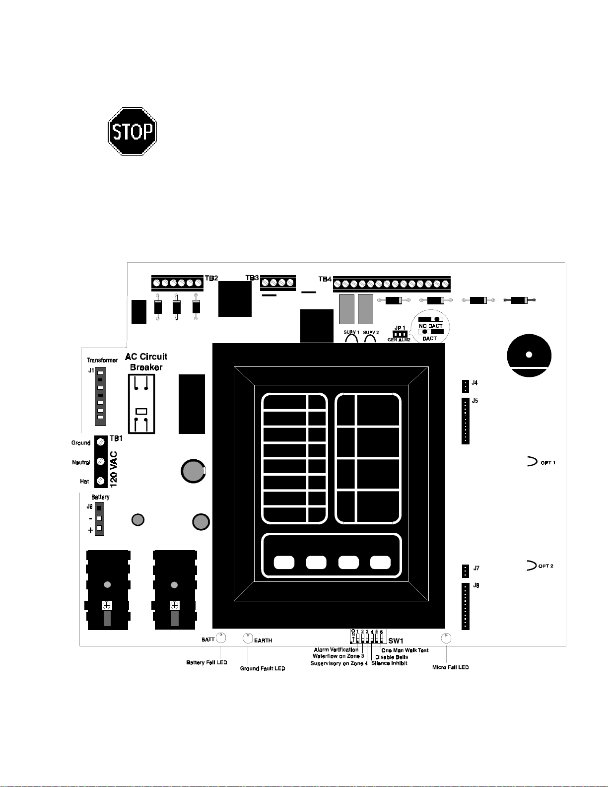
Figure 1.0-1: SFP-400B Installation Diagram
6
SFP-400B 15124:G1 06/24/97
Page 7

1.3 Optional Boards
The SFP-400B has mounting slots for two option boards. Two of the three option modules may be installed.
(see Section
Transmitter Module (4XTM)
The Transmitter Module provides a supervised output for local energy
municipal box transmitter (for NFPA 72-1993 Auxiliary Protective Signaling
System) and alarm and trouble reverse polarity circuits (for NFPA 72-1993
Remote Station Protective Signaling System). Also included is a DISABLE
switch and disable trouble LED.
polarity circuit will open on trouble if no alarm exists.
For Local Energy Municipal Box service (NFPA 72-1993 Auxiliary Fire
Alarm System)
Supervisory current: 5.0 mA.
Trip current: 0.35 amps (subtracted from Notification Appliance power).
Coil Voltage: 3.65 VDC.
Coil resistance: 14.6 ohms.
Maximum allowable wire resistance between panel and trip coil: 3 ohms.
Municipal Box wiring can leave the building.
For Remote Station service (NFPA 72-1993 Remote Station Fire Alarm
System):
Maximum load for each circuit: 10 mA.
Reverse polarity output voltage: 24 VDC.
Remote Alarm and Remote Trouble wiring can leave the building.
"Optional Modules"
)
As a jumper option, the alarm reverse
LED Interface Module (4XLM)
The LED Interface Module supports the RZA-4X Remote Annunciator
module. Annunciator wiring is supervised for open conditions by this
module. The Annunciator Driver Module mounts to the main board, occupying one of the two option connectors.
Notes:
Maximum voltage/current, each output: 27.6V/8mA.
Outputs are power limited.
Zone Relay Module (4XZM)
The Zone Relay module provides Form-C contacts for the following:
As a jumper option, the first four relays described below can be made silenceable.
• Alarm Zone 1
• Alarm Zone 2
• Alarm Zone 3
• Alarm Zone 4 or Supervisory (see Section
"Output Circuits"
)
• System Alarm
• System Trouble
Dry Form-C contacts rated:
2.0 amps @ 30 VDC (resistive),
0.5 amps @ 30 VAC (resistive).
Note: Use the Disconnect Switch located below the relays to disconnect the relays.
SFP-400B 15124:G1 06/24/97
7
Page 8

911AC Digital Communicator
The Noti•Fire 911AC is a stand-alone, three
channel Digital Alarm Communicator Transmitter (DACT) designed to provide for offpremises monitoring of a fire alarm control
panel. The 911AC is triggered by the alarm,
trouble, and/or supervisory contacts received
from the control panel and converts them into
digital transmission format. It communicates
with a digital receiver by means of one of two
transmission formats, BFSK or Pulsed Fast
Signal Round format.
Install the Noti•Fire 911AC Digital Communicator in accordance with the 911AC Installation Manual.
Interconnections between the control panel and the digital communicator are illustrated in Figure B-3.
Power Requirements: 24 VDC, 30 mA in Normal; 138 mA while communicating; 166.8 mA with alarm and
trouble relays while communicating.
Retard time and Reset time must be programmed for zero seconds when connecting the alarm initiating
circuit to an existing control panel.
For more detailed instructions, refer to the Noti•Fire 911AC manual, P/N 74-06200-005-A.
Note: 12V panels (SFP-400B) must use the 911AC.
1.4 Remote Annunciator
Notifier Remote Annunciator (RZA-4X)
The Remote Annunciator mounts on a standard single-gang box, and provides LED
indication of the following:
• Alarm Zone 1 (red)
• Alarm Zone 2 (red)
• Alarm Zone 3 (red)
• Alarm Zone 4 (red)
• System Trouble LED (yellow)
A Local Trouble Sounder and Silence Switch are also provided. All LED wiring is
supervised for open conditions. Any open condition will cause the System Trouble
LED to illuminate. Slide-in paper labels permit an easy change of zone information.
Note: The Remote Annunciator requires the use of an LED Interface module (4XLM).
8
SFP-400B 15124:G1 06/24/97
Page 9

1.5 Specifications
AC Power
For the SFP-400B: 120 VAC, 50/60 Hz, 1.2 amps
For the SFP-400BE: 220/240 VAC, 50 Hz, 0.6 amps
Wire size: minimum #14 AWG with 600V insulation
Battery (lead acid only)
Maximum Charging Circuit: 27.6V, 1.5 amps
Maximum Battery Capacity: 15 AH
(Batteries larger than 7 AH require Notifier BB-17 or similar UL listed battery cabinet).
Initiating Device Circuits
Power-limited circuitry
Operation: Style B (Class B)
Normal Operating Voltage: 24 VDC (ripple = 1.0V peak-to-peak)
Alarm current: 15 mA minimum
Short circuit current: 40 mA maximum
Maximum detector current in standby: 2 mA (max) per zone
Maximum loop resistance: 200 ohms
End-of-line resistor: 4.7K, 1/2-Watt
Detector loop current is sufficient to ensure operation of one alarmed detector per zone.
Supervisory current: 5 mA (including end-of-line resistor)
AC Circuit
Breaker
Notification Appliance Circuits
Power-limited circuitry
Maximum allowable voltage drop due to wiring: 2 VDC
Normal Operating Voltage: 24 VDC
Total current available to all external devices: 2.25 amps.
Maximum signaling current per circuit: 1.5 amps
End-of-line resistor: 4.7K, 1/2-Watt (part # 71252 UL listed)
Alarm and Trouble Relays
Dry Form-C contacts rated: 2.0 amps @ 30 VDC (resistive), 0.5 amps @ 30 VAC (resistive). All relays
must be connected to a power-limited power supply.
Four-wire Smoke Detector Power
Up to 200 mA is available for powering 4-wire smoke detectors.
Maximum ripple voltage: 1.0 V p/p
Non-resettable Power
Total DC current available from this output is up to 200 mA (subtracted from four-wire smoke power).
Maximum ripple voltage: 1.0 V p/p
Unregulated Power
Total DC current available for powering external devices is 0.5 amp (subtracted from 2.25 amps available
to notification appliance circuits).
Maximum ripple voltage: 100 mV p/p
Note: For device compatibility data, refer to the Device Compatibility Chart.
SFP-400B 15124:G1 06/24/97
9
Page 10

Door = 14.218"
Backbox = 14"
Cabinet = 3.047"
Backbox = 3.0"
Door = 14.718"
Backbox = 14.5"
10
Trim Ring
(TR-2-R)
Figure 1.5-1: Cabinet Dimensions
SFP-400B 15124:G1 06/24/97
Page 11

2.0 System Operation
2.1 System Status LEDs
Alarm, Trouble and Supervisory LEDs will flash on and off until the event(s) has been acknowledged
(TONE or ALARM SILENCE), at which point the LED will illuminate steadily.
AC POWER
Green LED that illuminates steadily to indicate presence of AC power.
SYSTEM ALARM
Red LED that flashes when an alarm occurs.
ALARM TEST
Red LED that illuminates during Walk Test.
SUPERVISORY
Yellow LED that flashes upon activation of a
supervisory device (such as tamper switch)
on Zone 4.
SYSTEM TROUBLE
Yellow LED that flashes for any trouble condition, including those associated with option
boards.
CIRCUIT TROUBLE
Yellow LED that flashes for trouble conditions
on output circuits (notification).
ALARM SILENCED
Yellow LED that illuminates steadily when the
ALARM SILENCE switch has been pushed
after an alarm.
POWER TROUBLE
Yellow LED that flashes for low or disconnected batteries and earth fault conditions.
BATT
Yellow LED that illuminates steadily on
motherboard when battery is low or not detected (not visible through door).
EARTH
Yellow LED that illuminates steadily on
motherboard during a ground fault condition
(not visible through door).
MICRO FAIL
Yellow LED that illuminates on motherboard
when watchdog timer detects microprocessor
failure (not visible through door).
SFP-400B 15124:G1 06/24/97
11
Page 12

2.2 Control Switches
Tone Silence
Acknowledge alarms, troubles and supervisories. The panel has alarm
and trouble resound with LED flash of new conditions. The flashing
trouble LED(s) illuminate steadily on TONE SILENCE and the piezo
sounder silences. A second trouble will resound the piezo. The piezo
has three distinct sounds for alarm, trouble, and supervisory. Trouble
conditions are self restoring. Alarms and supervisories latch and require
RESET to clear.
Alarm Silence
Acknowledge for alarms and supervisories. The ALARM SILENCE
switch will silence the local piezo, change any flashing alarm LEDs to
steady, and turn off the notification appliance circuits. The “ALARM
SILENCED” LED will illuminate. Alarm silence is a latching function and
requires a RESET to clear.
Note: If Silence Inhibit has been selected (SW1, DIP switch #4 set to "ON"),
the Alarm Silence will not function until 60 seconds after the initiation of the
alarm.
Alarm Activate
The ALARM ACTIVATE switch may be used to activate Notification
Appliance Circuits. ALARM ACTIVATE also activates the System
Alarm relay. ALARM ACTIVATE is a latching function. Pressing
ALARM SILENCE silences the notification appliance circuits and System Alarm Relay and lights the Alarm Silenced LED. Pressing RESET
returns the system to normal.
System Reset
The RESET switch breaks power to all initiating device circuits, 4-wire
smoke power and option boards and will clear any activated output
circuits. If any alarm or trouble still exists after reset, they will reactivate
the panel. Holding RESET down will perform a LAMP TEST function and
will activate the piezo sounder.
2.3 Zone Status LEDs
The alarm and/or trouble LED(s) will flash until the
event(s) has been acknowledged (TONE or
ALARM SILENCE), at which point the LED(s) will
illuminate steadily.
Note: If zone 4 is set for supervisory, the red alarm LED
is not used.
ALARM LED
TROUBLE
ALARM
TROUBLE
ALARM LED
TROUBLE
ALARM
TROUBLE
LED
LED
LED
LED
LED
LED
ZONE 1
ZONE 2
ZONE 3
ZONE 4
12
SFP-400B 15124:G1 06/24/97
Page 13

2.4 Supervisory
Zone 4 is always used for monitoring supervisory devices (such as valve tamper switches) by setting SW1
DIP switch 3 to "ON" (see Sections
circuit on this zone (activation of a N.O. contact) will cause the supervisory LED and the zone 4 yellow LED
to flash. The piezo sounder will generate a unique sound . Pressing TONE SILENCE will silence the piezo
and cause the supervisory LED to illuminate steadily,
Supervisory signals latch and require RESET to clear. The ALARM SILENCE switch will silence the piezo,
cause the supervisory LED to illuminate steadily and turn off the Supervisory Notification Appliance Circuit.
An open circuit on Zone 4 will be reported as a zone trouble.
2.5 Zone Disable
If a zone has been disabled, an alarm that occurs on that zone will flash
the red zone LED, but neither the piezo nor any output circuit will activate.
If both power sources are removed from the system, all zones will be reenabled upon restoration of power. Disable status will be lost.
The Zone Disable routine makes use of the four panel switches as follows:
1) Press and hold in the TONE SILENCE switch.
2) With the TONE SILENCE switch held in, press (in sequence) the ALARM
SILENCE switch, the ALARM ACTIVATE switch, and then the RESET
switch.
"Output Circuits"
and
"Dip Switch Location and Descriptions"
). A short
but the Zone 4 Trouble LED will continue to flash
.
3) The Zone 1 Alarm LED will flash.
4) To disable Zone 1, press the RESET switch. The Zone 1 yellow LED will light to show that the
zone is disabled.
Note: The RESET switch toggles disable status for the selected zone.
5) To select the next zone, press the ALARM SILENCE switch.
6) To select the previous zone, press the ALARM ACTIVATE switch.
7) When disable selections are complete, release the TONE SILENCE switch.
If any zone has been disabled, the trouble relay will activate and System Trouble LED will flash.
2.6 Last Event Recall
Last Event Recall allows the user to display the previous panel status. The last event recall uses the four
panel switches as follows:
1) Press and hold in the TONE SILENCE switch.
2) With the TONE SILENCE switch held in, press (in sequence) the RESET switch, the ALARM
ACTIVATE switch, and then the ALARM SILENCE switch.
3) Last Event is displayed.
4) Release the TONE SILENCE switch to return to normal operation.
5) To clear the Last Event buffer, press RESET twice.
SFP-400B 15124:G1 06/24/97
13
Page 14

3.0 Installation Procedure
3.1 General
Carefully unpack the system and check for shipping damage. Mount the cabinet in a clean, dry, vibrationfree area in which extreme temperatures are not encountered. The location should be readily accessible
with sufficient room for easy installation and maintenance. Locate the top of the cabinet approximately five
feet above the floor with the hinge mounting on the left. Determine the number of conductors required for
the devices to be employed. Pull required conductors into the box through the knockout provided. All wiring
should be in accordance with the National and/or Local codes for fire alarm systems.
UL Power Limited Wiring Requirements
Power limited and non-power limited circuit wiring must remain separated in the cabinet. All power limited
circuit wiring must remain at least 0.25" away from any non-power limited circuit wiring. Furthermore, all
power limited circuit wiring and non-power limited circuit wiring must enter and exit the cabinet through
different knockouts and/or conduits. A typical wiring diagram for the SFP-400B is shown below.
Power Limited Circuits
AC Power
Bell Circuits
PC Board
Initiating Circuits
Power
Limited
Circuit
Non-Power
Limited
Circuit
14
Figure 3.1-1: Typical Wiring Diagram for UL Power Limited Requirements
SFP-400B 15124:G1 06/24/97
Page 15

3.2 Initiating Device Circuits
Zones
Wire all alarm initiating devices sequentially for proper supervision. Initiating devices include: manual pull
stations, heat, photoelectric, and ionization type detectors; and waterflow alarm devices. Refer to the
Device Compatibility Chart.
Notes:
1) Observe polarity when connecting polarized devices.
2) All circuits are supervised and power limited.
3) Leave Dummy Load (provided) on all unused circuits.
TB4
Two-wire
Smoke
Detector
Heat Detector
Manual
Pull Station
Style B
Initiating
Device
Circuit
4.7K, 1/2-Watt
(part # 71252 )
+-
Style B
Initiating
Device
Circuit
4.7K, 1/2-Watt
(part # 71252 )
+-
Style B
Initiating
Device
Circuit
4.7K, 1/2-Watt
(part # 71252 )
+-
Style B
Supervisory
Circuit
(if SW1 switch
3 is set "ON")
Normally
Open
Tamper
Switch
+-
IN #1 IN #2 IN #3 IN #4
Figure 3.2-1: Example of Initiating Device Circuits
SFP-400B 15124:G1 06/24/97
15
Page 16

3.3 4-Wire Smoke Detector Connections
Refer to the Device Compatibility Document, for suitable 4-wire smoke detectors.
TB2
+ -
34
+24VR
A maximum of 200mA is available from the
+24VDC 4-wire smoke detector power circuit
on terminals 3 and 4. Any power that is drawn
from the +24VDC Non-Resettable Power on
terminals 5 and 6 must be subtracted from
available 4-wire detector power. (see Sections
"Specifications"
and
"Power"
)
24 VDC (+)
Common (-)
IDC(+)
IDC(-)
UL-listed 24 VDC
Four-Wire Smoke Detectors
TB4
B+ B-
Style B Initiating Device Circuit
Initiating Device Circuits 1, 2, 3, or 4
can be used.
24 VDC (+)
Common (-)
IDC(+)
IDC(-)
78
IN #1
Red
Black
UL Listed
4.7K, 1/2-Watt
ELR
Listed
Power
Supervision
Relay
Figure 3.3-1: Diagram of Connections for a 4-Wire Smoke Detector
Notes on Style B and Style D field wiring:
1) The Power Supervision Relay coil leads must be connected to the last detector base 24V screw terminals.
2) Calculation of the maximum allowable resistance in the 24VDC detector power wiring:
16
R
Where:
R
is the maximum resistance of the 24V wires.
MAX
is the minimum operating voltage of the detector or end-of-line relay, whichever is greater,
V
OM
in volts.
N is the total number of detectors on the 24V supply loop.
I
is the detector current in standby.
S
is the number of detectors on the 24V power loop which must function at the same time in
N
A
alarm.
IAis the detector current in alarm.
I
is the end-of-line relay current.
R
= (20.6 - VOM)
MAX
(N x I
S
SFP-400B 15124:G1 06/24/97
) + (NA x IA) + (IR)
Page 17

3.4 Output Circuits
Notification Appliance Circuits
The SFP-400B can provide two Notification Appliance Circuits (Style Y). Each circuit is capable of
providing up to 1.5 amps of current. Total current for both circuits and the unregulated power cannot
exceed 2.25 amps. Refer to the Device Compatibility Chart for suitable devices. Circuits are supervised
and power-limited.
Supervisory Appliance Circuit
If Supervisory Input is selected (see Section
Appliance Circuits will activate for supervisory conditions (either the SUPV1 or SUPV2 jumper must be
cut). To activate only one Notification Appliance Circuit (Circuit 2), cut jumper SUPV 1. To disable both
Notification Appliance Circuits, cut jumper SUPV 2 for supervisory conditions. (See figure below for jumper
location.)
If a 4XZM Relay Module is used, Relay 4 will activate for supervisories.
If an RZA-4X is used, the red LED 4 will annunciate supervisories.
Style Y
Notification
Appliance Circuit
4.7K, 1/2-Watt (part # 71252 UL listed)
Polarized Bell
"Dip Switch Location and Descriptions"
), both Notification
Polarized Strobe
Polarized Horn
TB3
Dummy Load
all unused
Circuits
4.7K, 1/2-Watt
B+ B- B+ B-
OUT #1 OUT #2
TB4
SUPV1
SUPV2
Figure 3.4-1: Notification Appliance Circuits
JP1
Alarm Relay
One Form-C dry alarm contact is provided in the basic panel for controlling supplementary devices. It is
rated 2 amps at 30 VDC and 0.5 amps at 30 VAC (resistive) and is non-silenceable when an alarm occurs.
See the following page for terminal location.
SFP-400B 15124:G1 06/24/97
17
Page 18

Trouble Relay
One Form-C dry trouble contact is provided in the basic panel for controlling supplementary devices. It
is rated 2 amps at 30 VDC, 0.5 amps at 30 VAC (resistive) and will silence when trouble condition is cleared.
See below for terminal location.
Note: The alarm and trouble Form-C dry contact relays must be power limited relays. Any Form-C dry contact
relay that may be used must be wired from one of the 24V power limited terminals as shown in the figure below
or a comparable UL listed power limited power supply.
ALARM TROUBLE
NO NC C NO NC C
or or
- - -
- - -
- - -
TB2
1 2 3 4 5 6
+ - + - + -
+24VU +24VR +24VNR
3.5 Po wer
CAUTION: Several different sources of power can be connected to this panel. Disconnect
all sources of power before servicing. The panel and associated equipment may be
damaged by removing and/or inserting cards, modules, or interconnecting cables while
this unit is energized.
This output is not suitable for powering devices requiring filtered, regulated DC power.
Unregulated Power
24 VDC power for inductive-type
devices such as door holders
can be connected to TB2 terminals 1(+) and 2 (-).
1 2 3 4 5 6
Alarm Trouble
Figure 3.4-2: Alarm / Trouble Coils and Contacts
The combined current draws from the Resettable and Non-Resettable outputs
cannot exceed 200 mA.
4-Wire Smoke Detector Power
24 VDC filtered, regulated, resettable power for 4-wire smoke detectors can be obtained from TB2
Terminals 3 (+) and 4 (-).
Non-resettable Power
24 VDC filtered, regulated, nonresettable power can be drawn
from TB2 Terminals 5 (+) and 6 (-).
TB4
18
+24VU +24VR +24VNR
+ - + - + -
TB2
1 2 3 4 5 6
Figure 3.5-1: Diagram of Power Terminals
AC Power
Primary power required for the SFP-400B panel is 120 VAC, 50/60 Hz, 1.2 amps and primary power
required for the SFP-400BE panel is 220/240 VAC, 50 Hz, 0.6 amps. Overcurrent protection for this circuit
must comply with Article 760 of the National Electrical Code (NEC) and/or local codes. Use #14 AWG or
larger wire with 600 volt rating.
SFP-400B 15124:G1 06/24/97
Page 19
Battery Power
Observe polarity when connecting battery. Connect battery cable to J9 on the main board using the plugin connector provided. See Appendix A for calculation of correct battery rating.
CAUTION: Batteries contain sulfuric acid which can cause severe burns to the skin
and eyes, and can destroy fabrics. If contact is made with sulfuric acid, immediately
flush skin or eyes with water for 15 minutes and seek immediate medical attention.
3.6 Optional Modules
This fire control panel has two module connectors - J5 and J8. Three modules are available for the panel
and they can be used in any combination, including duplicate modules (see notes below). The
corresponding option jumper must be cut before installation of an optional module, to enable module
supervision.
Figure 3.6-1: Option Panel Modules
Notes: Optional 4XLM module for an RZA-4X Annunciator must be installed on J7 and J8 only.
4XTM and 4XZM modules can be installed in either location.
SFP-400B 15124:G1 06/24/97
OPT1 Jumper
Cut to install module
on J5.
OPT2 Jumper
Cut to install module
on J8.
19
Page 20

Installing Option Modules
Insert the two nylon standoffs (provided) into the holes located on the right-side edge of the main board.
Carefully align the pins on the main board with J1 and/or J2 on the option board. Press firmly on the option
board until it locks in place on the standoffs. Affix the terminal identification labels provided with the option
modules as shown below.
(Part # 42050)
Standoffs
Option Board
(4XZM shown)
Main
Board
20
Figure 3.6-2: Installing Option Modules
SFP-400B 15124:G1 06/24/97
Page 21

Transmitter Module -- 4XTM
Polarities shown in activated positions. The wiring of this module must follow the requirements as specified
in the
"General"
Section
"UL Power Limited Wiring Requirements."
1
2
3
4
5
6
7
TBL Jumper
Disconnect
LED
Disconnect
Switch
Push the disconnect switch down to prevent unwanted activation of the Municipal Box during testing of the control
panel. The Disconnect LED will remain illuminated while the Municipal Box is disconnected. The System Trouble
LED will indicate disconnected and/or Open Circuit conditions on the Municipal Box.
Cutting the TBL jumper will allow the alarm reverse polarity circuit to open on trouble, if no alarm exists.
+
Remote Alarm
}
-
+
Remote Trouble
}
No Connection
+
Municipal Box *
}
-
* Dummy load terminals 6 and 7 (4.7K, 1/4 W resistor)
Power Limited Circuit
}
Non-Power Limited Circuit
}
if Municipal Box is not connected.
Note: Remote Alarm, Remote Trouble and Municipal Box wiring can leave the building.
SFP-400B 15124:G1 06/24/97
21
Page 22
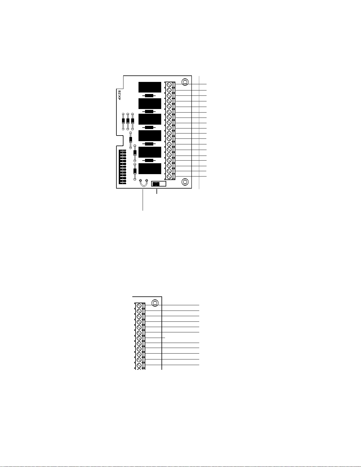
Zone Relay Module -- 4XZM
Non-power limited and power limited wiring must have a minimum distance of 0.25" wire to wire. If this
module is used to drive non-power limited and power limited circuits, please follow the instructions below:
Relay #1 through #4 will activate with Output #1 through #4
and remain latched unless jumper "LATCH" is cut.
1
NO
2
3
4
5
6
7
8
9
10
11
12
13
14
15
16
17
18
Use Disable switch to
disconnect the relays
NC
C
NO
NC
C
NO
NC
C
NO
NC
C
NO
NC
C
NO
NC
C
Relay #1
}
Relay #2
}
Relay #3
}
Relay #4
}
Alarm
}
Trouble
}
Cut jumper for non-latching
(silenceable) relay operation
1) Skip a set of dry contacts to maintain the 0.25" required space between power limited and non-power
limited circuits. The wiring of this module must follow the requirements as specified in the
Section
2) If this module is needed to drive power limited and non-power limited relays that are next to each other,
refer to the figure below showing a typical connection:
Note: Refer to the Protected Premises Unit label, located on the door of the control panel, to indicate if any dry
"UL Power Limited Wiring Requirements."
OR
Relay #1
Relay #2
Relay #3
Relay #4
contacts are to be used as non-power limited dry contacts.
NO
NC
}
NO
NC
}
NO
NC
}
NO
NC
}
C
C
C
C
no connection
}
}
}
}
power limited
circuit
power limited
circuit
non-power
limited circuit
non-power
limited circuit
"General"
22
SFP-400B 15124:G1 06/24/97
Page 23
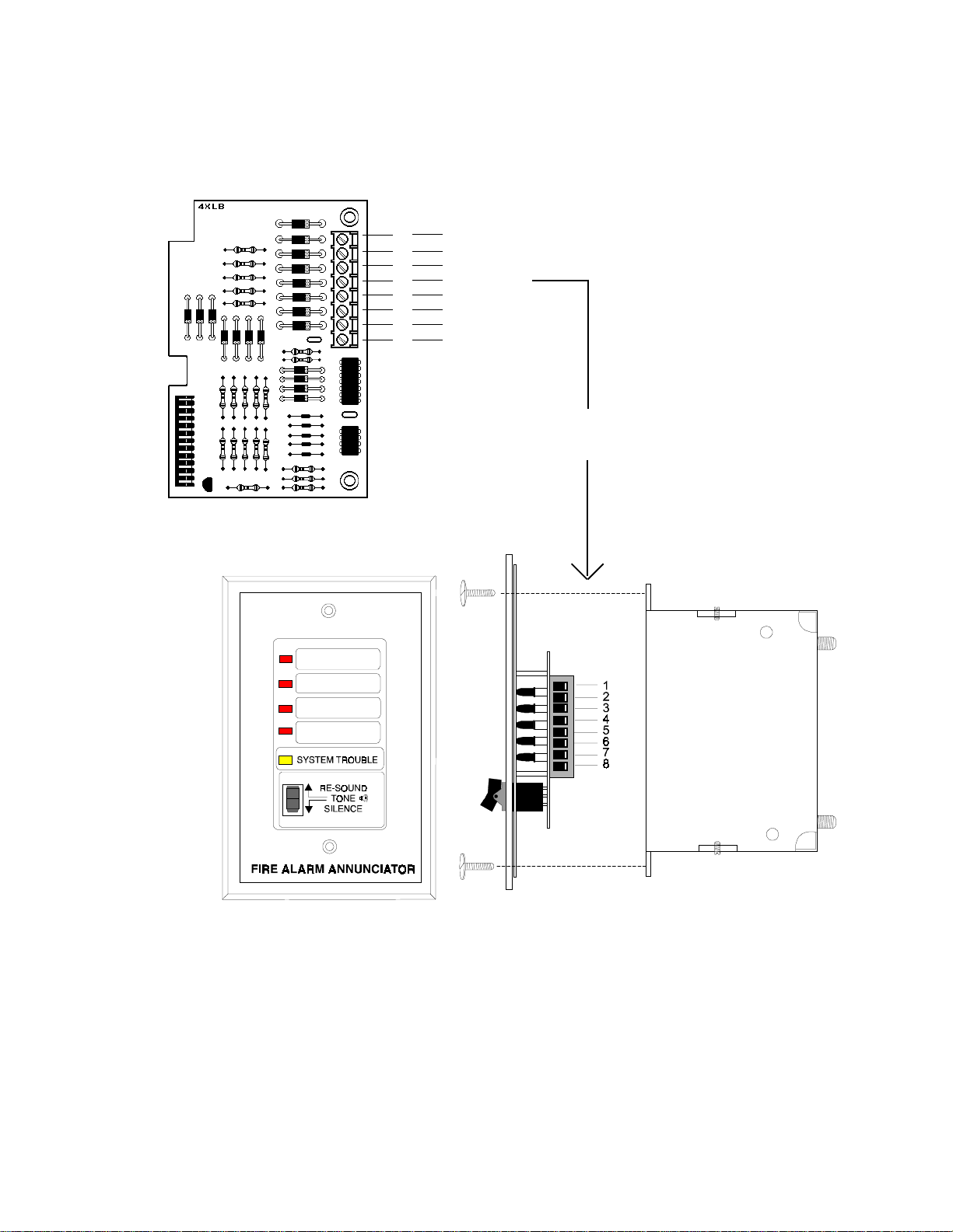
LED Interface Module -- 4XLM
The wiring of this module must follow the requirements as specified in the
Limited Wiring Requirements."
1
2
3
4
5
6
7
8
+24V
Out #1
Out #2
Out #3
Out #4
System Trouble
Sound
Resound
Connect to corresponding terminals of RZA4X Remote Annunciator.
Remote Annunciator -- RZA-4X
"General"
Section,
"UL Power
Side View
Front View
Single-gang Box
Figure 3.6-3: LED Interface Module--4XLM
Note:
Make wiring connections with system power off. Maximum wire impedance is 50 ohm per wiring connection.
SFP-400B 15124:G1 06/24/97
23
Page 24
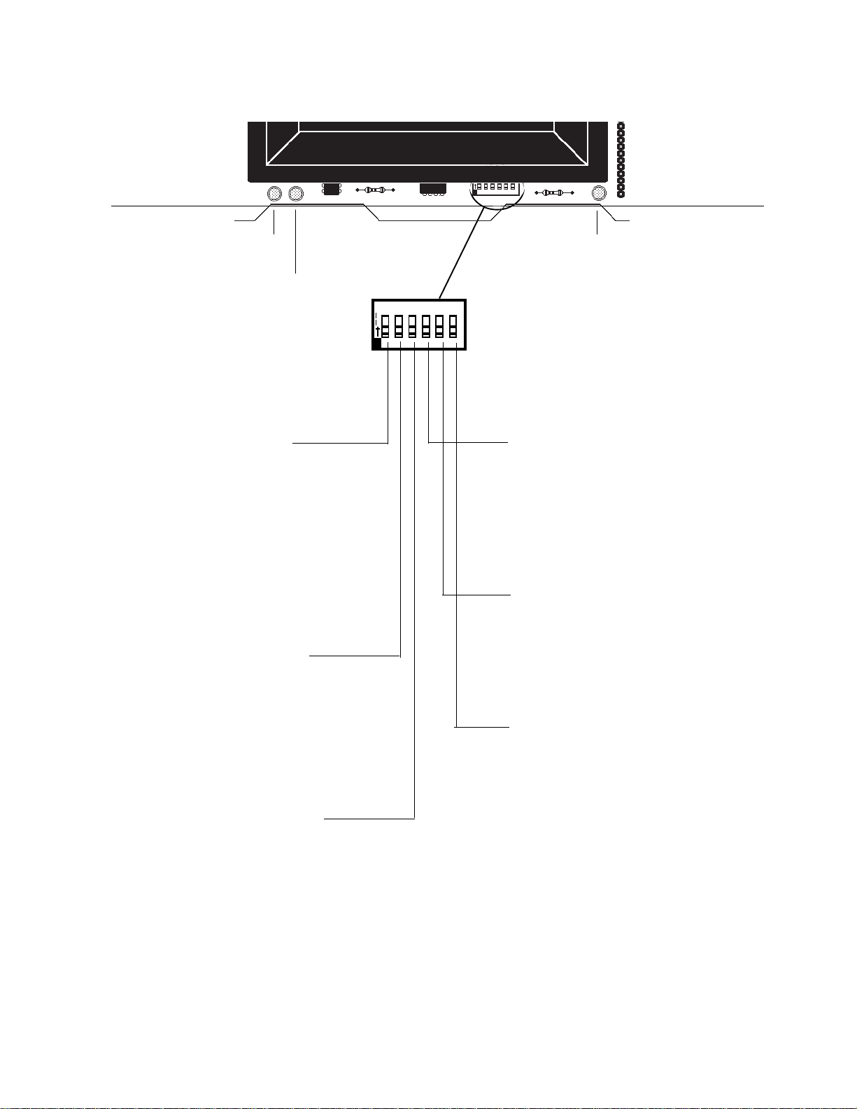
3.7 Dip Switch Location and Descriptions
Battery Fail
LED
Ground Fault LED
Switch 1: Alarm Verification
If selected, alarm signals that occur on any zone will
be subjected to a two-minute verification period to
determine if the alarm is true. Note that the control
panel will distinguish if the alarm signal came from
a shorting-type contact device (manual pull station,
4 wire detector, or heat detector) or a two-wire
smoke detector, and will not employ verification of
alarm signals from the contact devices.
Switch 2: Waterflow on Zone 3
If set for Waterflow, Initiating Device circuit 3 will
function as a waterflow circuit. If an alarm occurs on
this zone, the ALARM SILENCE switch will not
silence any activated output circuits.
Switch 3: Supervisory on Zone 4
If set for Supervisory, Initiating Device Circuit 4 will
function as a supervisory circuit. Activation of a
tamper or other supervisory switch on this circuit will
not result in an alarm condition. The piezo will sound
a distinct pulsing tone and the yellow LED on zone
4 will flash along with the supervisory LED. Notification Appliance Circuits 1 and 2 will activate (see
Section
"Output Circuits"
).
1 2 3 4 5 6
O
N
Micro Fail LED
To set a switch to the "ON" position,
slide it up.
Switch 4: Silence Inhibit
If selected and an alarm occurs, the
ALARM SILENCE switch will not function until 60 seconds have passed since
initiation of the alarm. If another alarm
occurs, the timer will restart at 60 seconds.
Switch 5: Disable Bells
When this switch is set "ON", the four
Indicating Appliance Circuits and the
SYSTEM ALARM relay will be disabled,
and a local trouble signal will be generated.
Switch 6: One Man Walk Test
Setting this switch to the "ON" position
places the control panel in Walk Test
Mode. The first alarm on Initiating Circuit under test will ring associated Indicating Circuit(s) for 5 seconds. Zone
Alarm LED will flash. The second alarm
on Initiating Circuit under test will ring
associated Notification Circuit(s) for 1
second. Zone Alarm LED will illuminate
Steadily. A Trouble condition on Initiating Circuit under test will sound piezo
and light Zone Trouble LED.
Note: The Reset key must depressed after any switch configuration has been made.
24
SFP-400B 15124:G1 06/24/97
Page 25
Appendix A: Power Calculations
Table A-1: Standby Battery Requirements
The Standby Battery Current figure obtained in Table A - 1 represents the amount of current that must
be supplied by the secondary power source (batteries) to sustain control panel operation for one hour.
Basic Control Panel 80 mA
Control panel with AC power off, System Trouble LED and audible trouble sounder on.
If using a 4XZM Zone Relay Module [ ] X 8 mA =
If using a 4XTM Transmitter Module, add 11 mA
If using the Reverse Polarity Alarm output, add 5 mA
If using the Reverse Polarity Trouble output, add 5 mA
If using a 4XLM/RZA-4X Driver/Annunciator combination:
[ 1 ] X 19 mA =
Auxiliary Power
If using a
a. Two-wire detector heads
b. Four-wire detector heads
c. End of Line Relays
d. Add lines a, b, & c for subtotal
911A
, add 30 mA
Number
in use
(see Device Compatibility
Document for data )
X=
X=
X 25.0 mA =
Device
Current
Place subtotal here :
Add last column for Standby Battery Current
and continue to Table A-2.
(113 mA for 60 hours of standby)
Total
Current
SFP-400B 15124:G1 06/24/97
25
Page 26

Table A-2: Ampere-Hour (AH) Calculations
Standby Battery Current Standby Time
Convert the total from Table 1 24 or 60 hours
to amps and enter here
amps X hours =
Enter 0.20 for 5 minutes in alarm or
+
0.4 for 10 minutes in alarm
Add Standby and Alarm AH =
Select a battery with an equal or greater AH rating than the figure obtained in Table A-2.
Batteries must be lead-acid type.
Batteries available from Notifier:
PS-1270 - 12-volt, 7 AH (two required)
PS-12120 - 12 volt, 12 AH (two required)
Notes:
1) Alarm AH assumes a maximum system draw of 2.4 amps in alarm for 5 minutes
(0.2 AH) or for 10 minutes (0.4 AH)
Standby AH
Alarm AH
Total AH
needed
26
2) NFPA 72-1993 Central Station, Local and Proprietary Protective Signaling Systems require 24 hours of
standby.
3) NFPA 72-1993 Auxiliary and Remote Station Protective Signaling Systems require 60 hours of standby.
4) The battery charger in this panel will charge a maximum of 15 amp/hours of batteries within 48 hours (7 amp/
hour minium). Batteries larger than 12 amp/hour will require a UL listed battery cabinet (e.g. Notifier BB-17).
SFP-400B 15124:G1 06/24/97
Page 27

Appendix B: NFPA Standard-Specific Requirements
The Notifier SFP-400B has been designed for use in commercial, industrial, and institutional applications and meets
the requirements for service under the National Fire Protection Association (NFPA) Standards outlined in this
appendix. The minimum system components required for compliance with the appropriate NFPA standard are
listed below.
SFP-400B Control Panel containing the main control board, cabinet (backbox and door), main supply transformer
and power supply.
Batteries (refer to Appendix A for Standby Power Requirements).
Initiating Devices - connected to one of the control panel's Initiating Device Circuits.
Notification Appliances - connected to one of the control panel's Notification Appliance Circuits.
The following additional equipment is needed for compliance with the NFPA standards listed below:
NFPA 72-1993 Signaling Systems for Central Station Service (Protected Premises Unit)
NOTI-FIRE 911A/911AC DACT - for connection to a compatible listed Central Station DACR or Protected
Premises Receiving Unit. This unit must be installed as outlined in Figure B-3A/B.
NFPA 72-1993 Auxiliary Protective Signaling System
4XTM Transmitter Module for connection to a compatible listed Local Energy Municipal Box. This unit must be
installed as outlined in Figure B-1.
NFPA 72-1993 Remote Station Protective Signaling System
4XTM Transmitter Module for connection to the Fire•Lite RS82-9 Remote Station Receiver. See Figure
B-2 for installation instructions for this unit
OR
NOTI-FIRE 911A/911AC DACT - For connection to a compatible listed remote station DACR. This unit must be
installed as outlined in Figure B-3A/B.
NFPA 72-1993 Proprietary Protective Signaling System
Potter EFT-C McCulloh Transmitter. See Figure B-4 for installation instructions for this unit .
SFP-400B 15124:G1 06/24/97
27
Page 28

Figure B-1: NFPA 72-1993 Auxiliary Protective Signaling System
All connections are power limited and supervised. This application is not suitable for separate transmission
of sprinkler supervisory or trouble conditions.
Note: Maximum loop resistance allowed for wiring from control panel to Municipal Box is 3 ohms.
+
Municipal Box Circuit
-
4XTM
Transmitter Module
(activated polarities shown)
+-
6
7
Note: Municipal Box wiring can leave the building.
Gamewell
Model M34-56
Local Energy
Municipal Box
28
SFP-400B 15124:G1 06/24/97
Page 29

Figure B-2: NFPA 72-1993 Remote Station Protective Signaling System
Intended for connection to a polarity reversal circuit of a remote station receiving unit having compatible
ratings. All connections are power limited and supervised with the exception of the reverse polarity loop.
Supervision of the loop is the responsibility of the receiver.
Fire•Lite RS82-9
Remote Station Receiver
UL listed
+ - + -
1
Remote Alarm
2
3
Remote Trouble
4
Note: Remote Alarm and Remote Trouble wiring can leave the building.
4XTM
Transmitter Module
(activated polarities shown)
SFP-400B 15124:G1 06/24/97
29
Page 30

Figure B-3A: NFPA 72-1993 Signaling Systems for Central Station Service
(Protected Premises Unit) and Remote Station Protective Service
NOTI-FIRE 911A DACT - for connection to a Central Station Receiver or Protected Premises Receiving Unit. This
unit must be installed as illustrated below. For additional information on the 911A, refer to document
74-06200-005.
If the NOTI-FIRE 911A is not mounted in the SFP-400B backbox all connections must be in conduit, less than 20'
in length in the same room.
Notes: The Maximum standby load shall be 125 mA. The Standby by Battery Requirement: 24VDC, 7AH Max.
To
27.6 VDC (+)
24 VDC (+)
(-) Common
Alarm
Trouble
Supervisory
Central
Station
Red
1 3 4 6
JP1
Black
STD DACT
NOTE on STD DACT:
Place jumper over pins 2 & 3, marked
DACT, when employing a DACT. This
directs the control panel to transmit all
trouble conditions except AC LOSS.
draobrehtoMA119
mralA
nepoyllamron
stcatnoc
elbuorT
nepoyllamron
stcatnoc
yrosivrepuS
nepoyllamron
stcatnoc
CDV42+
nommoC
CDV6.72+
1-4BT7dna6
3-4BT9dna8
4-4BT01
6-4BT11
21-1BTMZX421
dna6-4BTrepmuJ
01-1BTMZX4
5-2BT2
6-2BT4
daelyrettab)+(1
30
SFP-400B 15124:G1 06/24/97
Page 31

Figure B-3B: NFPA 72-1993 Signaling Systems for Central Station Service
(Protected Premises Unit) and Remote Station Protective Service
NOTI-FIRE 911AC DACT - for connection to a Central Station Receiver or Protected Premises Receiving Unit.
This unit must be installed as illustrated below. For additional information on the 911AC, refer to document
74-06200-005.
All connections between the FACP and 911AC must be in conduit, less than 20' in length in the same room.
Alarm
Trouble
Supervisory
To
Central
Station
1 3 4 6
JP1
STD DACT
NOTE on STD DACT:
Place jumper over pins 2 & 3,
marked DACT, when employing a DACT. This directs the
control panel to transmit all
trouble conditions except AC
LOSS.
draobrehtoMCA119
mralA
yllamron
nepo
stcatnoc
elbuorT
yllamron
nepo
stcatnoc
yrosivrepuS
1-4BT7dna6
3-4BT9dna8
4-4BT01
6-4BT11
21-1BTMZX421
SFP-400B 15124:G1 06/24/97
yllamron
nepo
stcatnoc
dna6-4BTrepmuJ
01-1BTMZX4
31
Page 32

Figure B-3C: Using an MS-5012 as a Slave Communicator
Secondary
Program the MS-5012 for slave application. Reference the Installation Manual for additional information.
Phone Line
Modular Cable
P/N MCBL-6
Primary
Active
Primary
Phone Line
Secondary
Active
J2
Kissoff
AC POWER TROUBLE
ALARM
RESET SILENCE MODE
J3
SUPERVISORY
TB2
1
2
3
4
5
6
7
8
9
10
11
12
13
14
TB3
Alarm
Trouble
Supervisory
1 2
120 VAC
HOT
Neutral
Ground
Black
White
Green
yellow
AC Wiring for DACT/FACP must be
connected to the same circuit.
2105-SMdraobrehtoM
mralA
1-2BT3-4BT
2-2BT1-4BT
elbuorT
3-2BT6-4BT
4-2BT4-4BT
yrosivrepuS
9-2BT
yellow
Red
Black
+
-
MZX4
21#
12VDC
Battery
2-7AH
1 2 3 4 5 6
32
01-2BT
SFP-400B 15124:G1 06/24/97
MZX4
01#
Page 33
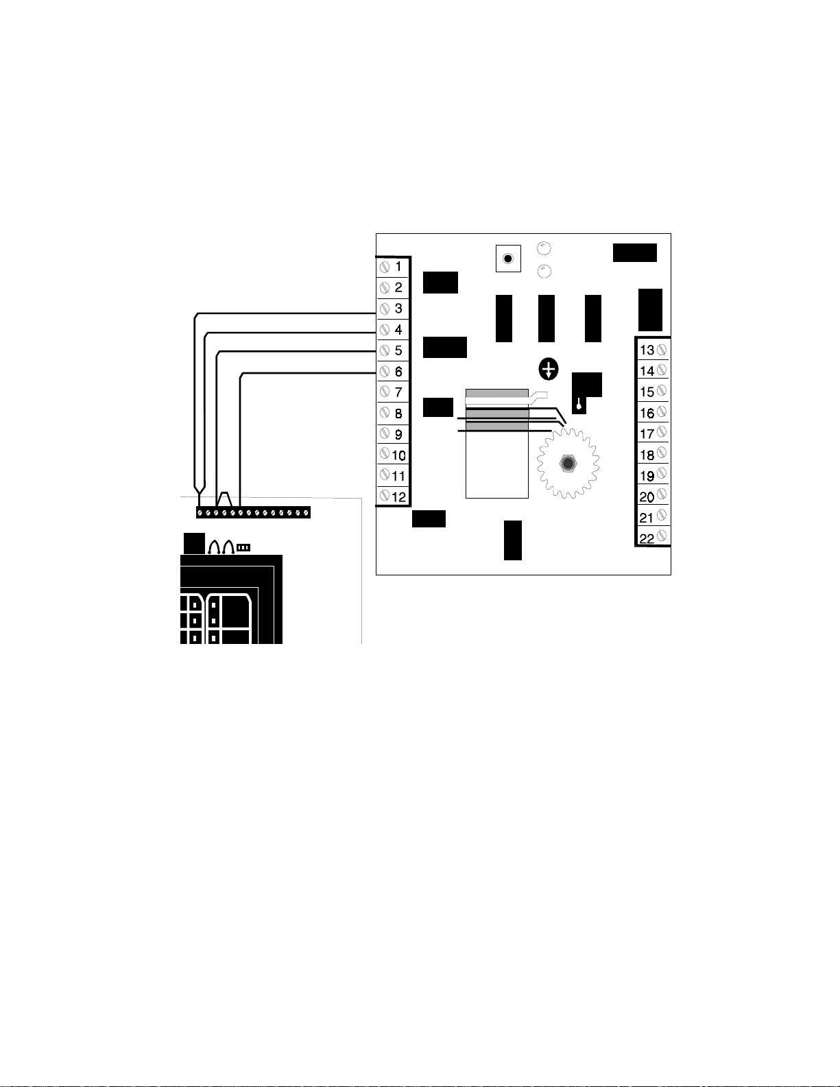
Figure B-4: NFPA 72-1993 Proprietary Protective Signaling System
Notes:
1) Connection between control panel and the transmitter are supervised by the transmitter.
2) Use transformer model ULT STK. NO. 1000391 (listed, Class 2, 12 V, 10 VA.). See Potter Electric Signal
Company Bulletin # 748.
3) This control panel/transmitter arrangement can be employed for NFPA 72-1993 Proprietary Protective
Signaling System.
TROUBLE
SFP-400B
RESET
ALARM
Notes:
Form-C Trouble contact which will automatically activate on any Trouble condition.
Form-C Alarm contact programmed to activate on General Alarm.
SFP-400B 15124:G1 06/24/97
33
Page 34

Trouble Shooting Table
MOTPMYS MELBORP
noDELelbuorttiucriCelbuorttiucricecnailppanoitacifitoN
nmulocthgirehtfoynA
gnihsalfsDELwolley
nmulocthgirehtfoynA
noDELelbuortmetsyS
noDELrewoPCA
no
nosDELdernmulocthgirehtfoynA gniriwtiucricgnitaitininotrohS
elbuortaetaerctonseod
snoitidnocyrosivrepusroelbuort
snoitidnocyrosivrepus
noDELwolleyliaForciMdegamadrossecorporciM
noyatssDELX4-AZRllA
ffoDELrewoPCA
noDELelbuortmetsyS
noDELwolleyliaForciMdegamadrossecorporciM
noydaetssDELwolley
noDELelbuortrewoP
MTX4noDELwolleY
MTX4nohctiwsxoBlapicinuMgnitcennocsiD
,mralarofetavitcat'nseodDELdetaicossa:MZX4
roelbuort,mralarofdnuost'nseodozeipX4-AZR
NOITULOS
.1rof3BT(.snoitcennocreporprof2BTkcehC
BX4)slenap
.2llatsnidnagniriwdleifllaevomeR
.3gniriwdleiftcennocer,RLEymmuddevomeR
.)V0trohs
.4.ecivedtsaltaRLErofkcehC
.5.gniriwdleifkcehC
.1.snoitcennocreporprof4BTkcehC
.2dnaelbuortnienozrofgniriwdleifevomeR
elbuorttiucricnepoenozgnitaitinI
.3.ecivedtsaltaRLErofkcehC
.4.gniriwdleifkcehC
elbasidenoZ
elbuortyrettaB
no
MTX4
MLX4
DELwolleyttaB
yrettab
elbuorttluafdnuorG
noDELwolleyhtraE
tucrepmuj2TPO,1TPO
tiucricnepoxoBlapicinuM
elbuorteludomlanoitpO
roirpdevomert'nsawrewoP
noitallatsni
rewopniamfossoL
rekaerbtiucricdegamaD
.1.launamnoitallatsnikcehC
rognissiM
.1.snoitcennocyrettabkcehC
detcennocsiD
.1regrahcssorcaegatlovkcehc,seirettabevomeR
egamadrowoL
.2taegatlovyrettaberusaem,seirettabtcennoceR
.3.seirettabecalper,tsisrepmelborpfI
.1dnalenapniammorfgniriwdleifevomeR
.2.sdaelyrettabhtobevomeR
.3emitehttatiucricenotcennoc,sraelcelbuortfI
.4.draobtiucricecalper,raelct'nseodelbuortfI
.11WShctiwstcennocsidxoBlapcinuMevoM
.pu
.1firepmujecalperro)s(eludomlanoitpollatsnI
.1noitpoxoBlapcinuMfidaolymmudllatsnI
.desut'nsi
.2.gniriwxoBlapcinuMkcehC
.1fI.RLEllatsnidnagniriwdleifevomeR
.secived
tuct'nsiseludomlanoitporofrepmuJ
.1.2TPOro1TPOrepmujdetaicossatuC
.1.dellatsniylreporpsieludomerusekaM
.2.tfelehtotMZX4no1WShctiwselbasidevoM
.17JnodellatsnisieludomMLX4tahterusekaM
.8Jdna
.2.gniriwdleifkcehC
.1.draobtiucricecalpeR
.1.tesermetsystiH
.1rof1BT(.)5BT(rewopgnimocnikcehCBX4
)slenap
.1.draobtiucricecalpeR
.1.draobtiucricecalpeR
rofkcehC.tiucrictuptuotaRLEymmud
,)V3.2-lamroN(,tissorcaegatlovyrosivrepus
.draobtiucricecalper,tsisrepmelborpfi
,V5-elbuort(;tuptuossorcaegatloverusaemdna
rofK2.2;V42rofK7.4(RLEymmudllatsni
.draobtiucricecalper,tsisrepmelborpfI.)V21
,)V21rofV01-8;V42rofV91ot71(tuptuo
.draobtiucricecalperesiwrehto
fo%58nahtsselsiegatlovfI.slanimretyrettab
.sruoh84rofegrahcotmehtwolla,egatlovdetar
ymmudllatsnI.)dellatsnifi()s(eludomlanoitpo
.)V21rofK2.2;V42rofK7.4(RLE
.melborpehttniopnipot
.desutonsi)s(eludom
deriwyltcerrocniroytluafrofkool,sraelcelbuort
34
SFP-400B 15124:G1 06/24/97
Page 35

NOTES
SFP-400B 15124:G1 06/24/97
35
Page 36

Limited W arranty
NOTIFIER® warrants its products to be free from defects in materials and wo rkmanship
for eighteen (18) months from the date of manufacture , under normal use and service.
Products are date stamped at time of manufacture. The sole and exclusiv e obligation
of NOTIFIER® is to repair or replace, at its option, free of charge for parts and labor,
any part which is defective in materials or workmanship under normal use and service.
For products not under NOTIFIER® manufacturing date-stamp control, the warranty
is eighteen (18) months from date of original purchase by NOTIFIER®'s distributor
unless the installation instructions or catalog sets forth a shorter per iod, in which
case the shorter period shall apply. This warranty is void if the product is altered,
repaired or serviced by anyone other than NO TIFIER® or its authorized distributors or
if there is a failure to maintain the products and systems in which they operate in a
proper and workable manner . In case of def ect, secure a Return Material Authorization
form from our customer service department. Return product, transportation prepaid,
to NOTIFIER®, 12 Clintonville Road, Northford, Connecticut 06472-1653.
This writing constitutes the only warranty made by NOTIFIER® with respect to its
products. NOTIFIER® does not represent that its products will prevent any loss by
fire or otherwise, or that its products will in all cases provide the protection for which
they are installed or intended. Buyer ackno wledges that NOTIFIER® is not an insurer
and assumes no risk for loss or damages or the cost of any inconvenience,
transportation, damage, misuse, abuse, accident or similar incident.
NOTIFIER® GIVES NO WARRANTY, EXPRESSED OR IMPLIED, OF
MERCHANTABILITY, FITNESS FOR ANY PARTICULAR PURPOSE, OR
OTHERWISE WHICH EXTEND BEYOND THE DESCRIPTION ON THE FACE
HEREOF. UNDER NO CIRCUMSTANCES SHALL NOTIFIER® BE LIABLE FOR ANY
LOSS OF OR DAMAGE TO PROPERTY, DIRECT, INCIDENTAL OR
CONSEQUENTIAL, ARISING OUT OF THE USE OF, OR INABILITY TO USE
NOTIFIER® PRODUCTS. FURTHERMORE, NOTIFIER® SHALL NOT BE LIABLE
FOR ANY PERSONAL INJURY OR DEATH WHICH MAY ARISE IN THE COURSE
OF, OR AS A RESULT OF, PERSONAL, COMMERCIAL OR INDUSTRIAL USE OF
ITS PRODUCTS.
This warranty replaces all previous warranties and is the only warranty made by
NOTIFIER®. No increase or alteration, written or verbal, of the ob ligation of this warranty
is authorized.
"NOTIFIER" is a registered trademark.
12 Clintonville Road, Northford, CT 06472
Phone: (203) 484-7161
FAX: (203) 484-7118
Technical Publishing Document WARNBG-C.P65 04/02/96
 Loading...