

Page 1

ONYXWorks
®
NFN Gateway
PC
Installation & Operation Manual
Document 52307
06/01/07 Rev:
P/N: 52307:D ECN: 06-053
D
Page 2

Fire Alarm System Limitations
While a fire alarm system may lower insurance rates, it is not a substitute for fire insurance!
An automatic fire alarm system—typically made up of smoke detec-
tors, heat detectors, manual pull stations, audible warning devices,
and a fire alarm control panel with remote notification capability—can
provide early warning of a developing fire. Such a system, however,
does not assure protection against property damage or loss of life
resulting from a fire.
The Manufacturer recommends that smoke and/or heat detectors be
located throughout a protected premise following the recommendations of the current edition of the National Fire Protection Association
Standard 72 (NFPA 72), manufacturer's recommendations, State and
local codes, and the recommendations contained in the Guide for
Proper Use of System Smoke Detectors, which is made available at
no charge to all installing dealers. These documents can be found at
http://www.systemsensor.com/html/applicat.html.
A study by the Federal Emergency Management Agency (an agency
of the United States government) indicated that smoke detectors may
not go off in as many as 35% of all fires. While fire alarm systems are
designed to provide early warning against fire, they do not guarantee
warning or protection against fire. A fire alarm system may not provide timely or adequate warning, or simply may not function, for a
variety of reasons:
Smoke detectors may not sense fire where smoke cannot reach the
detectors such as in chimneys, in or behind walls, on roofs, or on the
other side of closed doors. Smoke detectors also may not sense a
fire on another level or floor of a building. A second-floor detector, for
example, may not sense a first-floor or basement fire.
Particles of combustion or “smoke” from a developing fire may not
reach the sensing chambers of smoke detectors because:
• Barriers such as closed or partially closed doors, walls, or chimneys
may inhibit particle or smoke flow.
• Smoke particles may become “cold,” stratify, and not reach the ceiling
or upper walls where detectors are located.
• Smoke particles may be blown away from detectors by air outlets.
• Smoke particles may be drawn into air returns before reaching the
detector.
The amount of “smoke” present may be insufficient to alarm smoke
detectors. Smoke detectors are designed to alarm at various levels of
smoke density. If such density levels are not created by a developing
fire at the location of detectors, the detectors will not go into alarm.
Smoke detectors, even when working properly, have sensing limitations. Detectors that have photo-electronic sensing chambers tend to
detect smoldering fires better than flaming fires, which have little visible smoke. Detectors that have ionizing-type sensing chambers tend
to detect fast-flaming fires better than smoldering fires. Because fires
develop in different ways and are often unpredictable in their growth,
neither type of detector is necessarily best and a given type of detector may not provide adequate warning of a fire.
Smoke detectors cannot be expected to provide adequate warning of
fires caused by arson, children playing with matches (especially in
bedrooms), smoking in bed, and violent explosions (caused by escaping gas, improper storage of flammable materials, etc.).
Heat detectors do not sense particles of combustion and alarm only
when heat on their sensors increases at a predetermined rate or
reaches a predetermined level. Rate-of-rise heat detectors may be
subject to reduced sensitivity over time. For this reason, the rate-ofrise feature of each detector should be tested at least once per year
by a qualified fire protection specialist. Heat detectors are designed
to protect property, not life.
IMPORTANT! Smoke detectors must be installed in the same room
as the control panel and in rooms used by the system for the connection of alarm transmission wiring, communications, signaling, and/or
power. If detectors are not so located, a developing fire may damage
the alarm system, crippling its ability to report a fire.
Audible warning devices such as bells may not alert people if these
devices are located on the other side of closed or partly open doors or
are located on another floor of a building. Any warning device may
fail to alert people with a disability or those who have recently consumed drugs, alcohol or medication. Please note that:
• Strobes can, under certain circumstances, cause seizures in people
with conditions such as epilepsy.
• Studies have shown that certain people, even when they hear a fire
alarm signal, do not respond or comprehend the meaning of the signal.
It is the property owner's responsibility to conduct fire drills and other
training exercise to make people aware of fire alarm signals and
instruct them on the proper reaction to alarm signals.
• In rare instances, the sounding of a warning device can cause temporary or permanent hearing loss.
A fire alarm system
will not operate without any electrical power. If
AC power fails, the system will operate from standby batteries only for
a specified time and only if the batteries have been properly maintained and replaced regularly.
Equipment used in the system may not be technically compatible
with the control panel. It is essential to use only equipment listed for
service with your control panel.
Telephone lines needed to transmit alarm signals from a premise to a
central monitoring station may be out of service or temporarily disabled. For added protection against telephone line failure, backup
radio transmission systems are recommended.
The most common cause of fire alarm malfunction is inadequate
maintenance. To keep the entire fire alarm system in excellent working order, ongoing maintenance is required per the manufacturer's
recommendations, and UL and NFPA standards. At a minimum, the
requirements of NFPA 72 shall be followed. Environments with large
amounts of dust, dirt or high air velocity require more frequent maintenance. A maintenance agreement should be arranged through the
local manufacturer's representative. Maintenance should be scheduled monthly or as required by National and/or local fire codes and
should be performed by authorized professional fire alarm installers
2 NFN Gateway Installation & Operation Manual - P/N: 52307:Rev: D 06/01/07
Page 3

Installation Precautions
Adherence to the following will aid in problem-free installation with long-term reliability:
WARNING - Several different sources of power can be connected to
the fire alarm control panel.
servicing. The control unit and associated equipment may be damaged by removing and/or inserting cards, modules, or interconnecting
cables while the unit is energized. Do not attempt to install, service,
or operate this unit until this manual is read and understood.
CAUTION - System Reacceptance Test after Software Changes. To
ensure proper system operation, this product must be tested in accordance with NFPA 72 after any programming operation or change in
site-specific software. Reacceptance testing is required after any
change, addition or deletion of system components, or after any modification, repair or adjustment to system hardware or wiring.
All components, circuits, system operations, or software functions
known to be affected by a change must be 100% tested. In addition,
to ensure that other operations are not inadvertently affected, at least
10% of initiating devices that are not directly affected by the change,
up to a maximum of 50 devices, must also be tested and proper system operation verified.
This system meets NFPA requirements for operation at 0°C to 49°C
(32°F to 120°F) and at a relative humidity 93% ± 2% RH (non-condensing) at 32°C ± 2°C (90°F ± 3°F). However, the useful life of the
system's standby batteries and the electronic components may be
adversely affected by extreme temperature ranges and humidity.
Therefore, it is recommended that this system and all peripherals be
installed in an environment with a nominal room temperature of 1527° C/60-80° F.
Verify that wire sizes are adequate for all initiating and indicating
device loops. Most devices cannot tolerate more than a 10% I.R.
drop from the specified device voltage.
Disconnect all sources of power before
Like all solid state electronic devices this system may operate errati-
cally or can be damaged when subjected to lightning-induced transients. Although no system is completely immune from lightning
transients and interferences, proper grounding will reduce susceptibility. Overhead or outside aerial wiring is not recommended, due to an
increased susceptibility to nearby lightning strikes. Consult with the
Technical Services if any problems are anticipated or encountered.
Disconnect AC power and batteries prior to removing or inserting cir-
cuit boards. Failure to do so can damage circuits.
Remove all electronic assemblies prior to any drilling, filing, reaming,
or punching of the enclosure. When possible, make all cable entries
from the sides or rear. Before making modifications, verify that they
will not interfere with battery, transformer, and printed circuit board
location.
Do not tighten screw terminals more than 9 in-lbs. Over-tightening
may damage threads, resulting in reduced terminal contact pressure
and difficulty with screw terminal removal.
Though designed to last many years, system components can fail at
any time. This system contains static-sensitive components. Always
ground yourself with a proper wrist strap before handling any circuits
so that static charges are removed from the body. Use static-suppressive packaging to protect electronic assemblies removed from
the unit.
Follow the instructions in the installation, operating, and program-
ming manuals. These instructions must be followed to avoid damage
to the control panel and associated equipment. FACP operation and
reliability depend upon proper installation by authorized personnel.
FCC Warning
WAR NING: This equipment generates, uses, and can radi-
ate radio frequency energy and if not installed and used in
accordance with the instruction manual, may cause interference to radio communications. It has been tested and
found to comply with the limits for class A computing
device pursuant to Subpart B of Part 15 of FCC Rules,
which is designed to provide reasonable protection against
such interference when operated in a commercial environment. Operation of this equipment in a residential area is
Acclimate Plus™
ONYX®, FlashScan®, UniNet®, VIEW®, NOTIFIER® are registered trademarks of Honeywell. Simplex® is registered trademark of Tyco
International Ltd. Echelon®
Corporation.
General Electric Company.
©2006 by Honeywell International Inc. All rights reserved. Unauthorized use of this document is strictly prohibited.
, HARSH™, NOTI•FIRE•NET™, VeriFire™, NION™, NOTIFER Intergrated Systems™ and ONYXWorks™ are trademarks, and
is a registered trademark and LonWorks™ is a trademark of Echelon Corporation. ARCNET® is a registered trademark of Datapoint
Microsoft® and Windows® are registered trademarks of the Microsoft Corporation. LEXAN® is a registered trademark of GE Plastics, a subsidiary of
likely to cause interference, in which case the user will be
required to correct the interference at his own expense.
Canadian Requirements: This digital apparatus does not
exceed the Class A limits for radiation noise emissions
from digital apparatus set out in the Radio Interference
Regulations of the Canadian Department of Communications.
Le present appareil numerique n'emet pas de bruits radioelectriques depassant les limites applicables aux appareils
numeriques de la classe A prescrites dans le Reglement
3NFN Gateway Installation & Operation Manual - P/N: 52307:Rev: D 06/01/07
Page 4

Documentation Feedback
Your feedback helps us keep our documentation up-to-date and accurate. If you have any comments, you can email
us.
Please include the following information:
• Product name and version number (if applicable)
• Manual page number
• Your comment
Send email messages to:
FireSystems.TechPubs@honeywell.com
Please note this email address is for documentation feedback only. If you have any technical issues, please contact
Technical Services.
4 NFN Gateway Installation & Operation Manual - P/N: 52307:Rev: D 06/01/07
Page 5

Table of Contents
Section 1 NFN Gateway PC Overview..................................................................................... 7
1.1: Product Description .......................................................................................................................................7
Table 1.1 NFN Network Compatibility Table........................................................................................7
1.2: NFN Gateway PC System Architecture ........................................................................................................8
Figure 1.1 Direct Panel Gateway System...............................................................................................8
Figure 1.2 ONYXWorks
Figure 1.3 ONYXWorks
1.2.1: About Ethernet Network Installations .................................................................................................9
1.3: Gateway Configuration Process Flow Diagram ..........................................................................................10
Figure 1.4 Overall Gateway Configuration Process Flow Diagram.....................................................10
1.4: ONYXWorks
1.4.1: Network Interface Card .....................................................................................................................11
1.4.2: Workstation Power Supply Supervision............................................................................................11
1.5: Agency Listings ...........................................................................................................................................11
1.5.1: Environmental Requirements ............................................................................................................12
1.6: Related Documentation ...............................................................................................................................12
®
System/NFN Gateway Requirements.................................................................................11
Section 2 NFN Gateway PC Configuration ........................................................................... 13
2.1: NFN Gateway PC Software Installation......................................................................................................13
2.1.1: Required Equipment..........................................................................................................................13
2.2: About the Network Interface Card Installation ...........................................................................................13
2.2.1: Network Interface Card Layout.........................................................................................................14
Figure 2.1 NFN-GW-PC-W Card Layout ............................................................................................14
Figure 2.2 NFN-GW-PC-F Card Layout..............................................................................................14
Table 2.1 NCS-NCW/F Status LEDs ...................................................................................................15
2.2.2: Network Interface Card Installation Procedure.................................................................................16
2.2.3: Network Interface Card Cable Connections......................................................................................17
Figure 2.3 Workstation to IP Connection.............................................................................................17
Figure 2.4 Workstation to NFN Network Connection .........................................................................17
2.3: NFN Gateway PC Configuration Procedure................................................................................................18
2.3.1: NFN Gateway Settings ......................................................................................................................18
Figure 2.5 Gateway Node Selection.....................................................................................................18
Figure 2.6 Gateway Login Window .....................................................................................................18
Figure 2.7 NFN Gateway PC NCM Address Setting ...........................................................................18
Figure 2.8 NFN Gateway PC Mode Setting.........................................................................................19
2.3.2: Login Password Settings ...................................................................................................................19
Figure 2.9 Gateway Login - Change Password....................................................................................19
®
System Example 1- One NFN Network......................................................8
®
System Example 2 - Multiple NFN Networks ............................................9
Section 3 NFN Config Tool Reference Information .............................................................21
3.1: NFN Config Tool Description .....................................................................................................................21
3.2: Property/Value Field Descriptions...............................................................................................................21
Figure 3.1 NFN Gateway PC Property and Values..............................................................................21
3.2.1: GATEWAY SETTINGS Fields ........................................................................................................21
3.2.2: Panel Properties Fields ......................................................................................................................22
Figure 3.2 NFN Config Tool Panel Property/Value Field Descriptions ..............................................22
3.3: Menu Descriptions.......................................................................................................................................23
3.3.1: File.....................................................................................................................................................23
3.3.2: View...................................................................................................................................................23
3.3.3: Tools ..................................................................................................................................................23
3.3.4: Help ...................................................................................................................................................23
Index.........................................................................................................................................25
5NFN Gateway - P/N: 52307:Rev: D 06/01/07
Page 6

Table of Contents
6 NFN Gateway - P/N: 52307:Rev: D 06/01/07
Page 7

Section 1 NFN Gateway PC Overview
NOTE: In this document, unless expressly written otherwise, when the term ONYXWorks
Workstation or Workstation is used those terms refer to the software application and the computer
it is installed on as one.
1.1 Product Description
This gateway:
• Serves as a bridge between an ONYXWorks
Workstation as the primary reporting station for the NFN network.
• Translates a NFN network’s panel and device data into data that can be interpreted by the
ONYXWorks
• Monitors NFN networks using ARCNET network architecture.
• Is configured using the NFN Config Tool.
The NFN Gateway PC enables remote users to monitor a NFN network with a Workstation that is
registered on your IP network. The gateway is used in conjuncture with Veri•Fire™ Tools software
application to upload/download data to a panel without having to physically visit the panel.
The NFN Gateway PC acts like any other node on a NFN network and is compatible with the
following node type. An * indicates panels that support using a USB or serial cable for the direct
connections as shown in Figure 1.1 on page 8.
®
Workstation software application.
®
®
Workstation and a NFN network, and it uses that
Table 1.1 NFN Network Compatibility Table
NFN Network Node Type Network Board Used
AFP-200 NAM
AFP-300/400 NAM
AFP-1010 SIB-NET
AM2020 SIB-NET
BACnet Gateway NCM-W/F
BACnet Gateway-2 NCM-W/F
DAA
DVC NCM-W/F
NFS-320* NCM-W/F
NFS-640 NCM-W/F
NFS2-640* NCM-W/F
NFS-3030 NCM-W/F
NFS2-3030* NCM-W/F
NFN Web Server NCM-W/F
NCA NCM-W/F
NCA-2* NCM-W/F
NCS NCM-W/F
7NFN Gateway Installation & Operation Manual - P/N: 52307:Rev: D 06/01/07
Page 8
NFN Gateway PC Overview NFN Gateway PC System Architecture
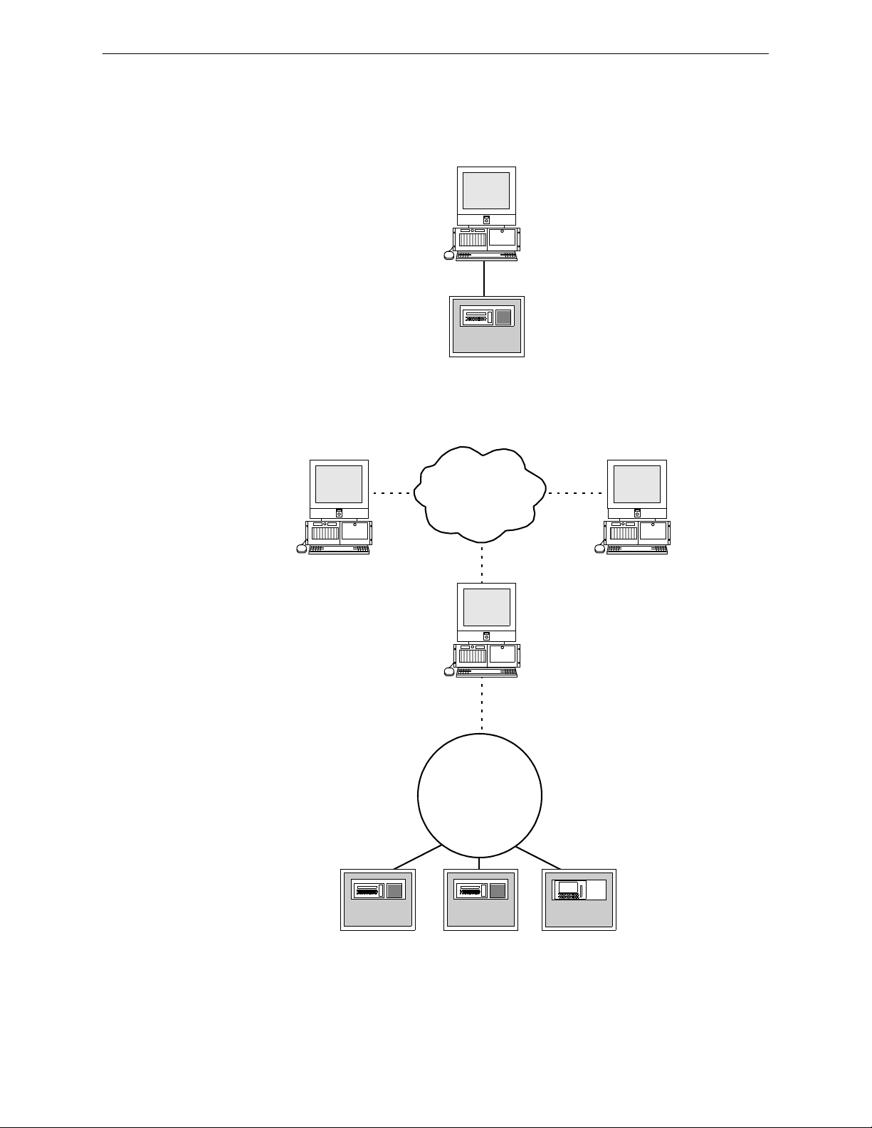
1.2 NFN Gateway PC System Architecture
An ONYXWorks® system must have at least one Workstation. A Workstation can monitor or
control a node and its points on the NFN network through the gateway. Refer to Figure 1.2 and
Figure 1.3 for network diagrams.
Workstation/
Gateway PC
Serial Data or USB Connection
FACP
Figure 1.1 Direct Panel Gateway System
Workstation
IP Network
Workstation
Workstation/
Gateway PC
NFN Network
FACP FACP
Figure 1.2 ONYXWorks
FACP
®
System Example 1- One NFN Network
8 NFN Gateway Installation & Operation Manual - P/N: 52307:Rev: D 06/01/07
Page 9

NFN Gateway PC System Architecture NFN Gateway PC Overview
IP Network
Workstation
Workstation
Gateway
Embedded
Workstation/Echelon
Gateway
Style 4, 6, or 7
Echelon Network
Wire or Fiber, ULC
Style DCLA, DCLB,
and DCLR
Gateway PC
NFN Network
NION NION NION
FACP
FACP
FACP
FACP FACP
Figure 1.3 ONYXWorks® System Example 2 - Multiple NFN Networks
1.2.1 About Ethernet Network Installations
The ONYXWorks® Workstation is a Proprietary Supervising Station that has a supervised client
server architecture that communicates over Ethernet (TCP/IP) networks. The IP network can be a
shared bandwidth system that operates over topologies such as an intranet, the Internet, or a frame
relay system. ULC does not allow operation over an Internet connection.
ONYXWorks
systems, multiple computers can be networked together over the IP network running multiple
instances of the Workstation software application or other clients and gateways.
If the Workstation or gateway are sharing on-premises communications equipment, the shared
equipment shall be “listed for the purpose”. “Listed for the purpose” has been formally interpreted
by NFPA (Formal Interpretation 72-99-1) for equipment on packet switched networks as being
listed to the requirements applicable to general purpose communications network equipment.
®
clients, in the most basic system, can co-exist on one computer. For more powerful
NFN Network
FACP
For ULC applications, the Internet cannot be used for either primary or ancillary functionality.
9NFN Gateway Installation & Operation Manual - P/N: 52307:Rev: D 06/01/07
Page 10
NFN Gateway PC Overview Gateway Configuration Process Flow Diagram
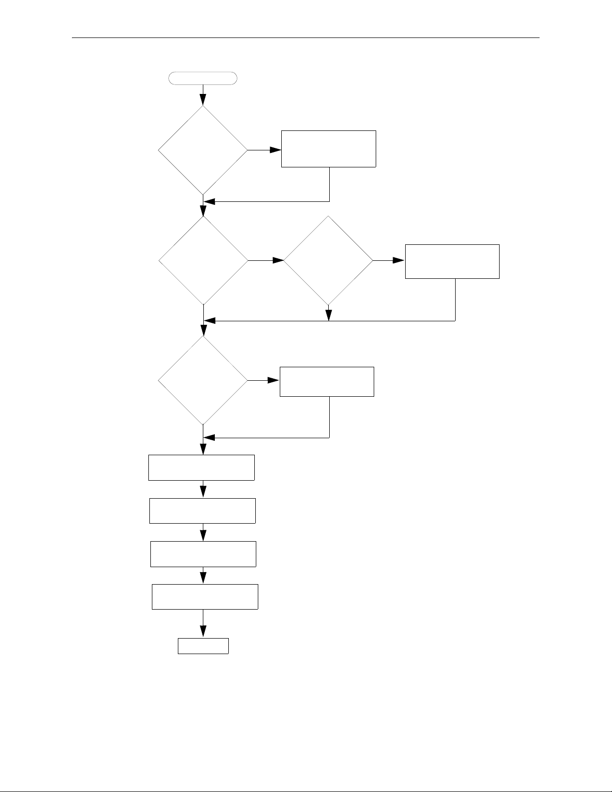
1.3 Gateway Configuration Process Flow Diagram
Start
Is the
gateway
software already
installed on the
Workstation PC?
Yes
No
“NFN Gateway PC
Software Installation” on
page 13
Using Network
Interface Card?
No
Need to connect
Network
Interface Card?
No
“NFN Gateway Settings” on
page 18
“About the NFN Gateway
Mode Setting” on page 19
Yes
Yes
Interface Card
“Network Interface Card
Cable Connections” on
Network
Already
Installed?
page 17
Yes
“Network Interface Card
No
Installation Procedure”
on page 16
“NCM Address Setting” on
“Login Password Settings”
page 18
on page 19
Finished
Figure 1.4 Overall Gateway Configuration Process Flow Diagram
10 NFN Gateway Installation & Operation Manual - P/N: 52307:Rev: D 06/01/07
Page 11

ONYXWorks® System/NFN Gateway Requirements NFN Gateway PC Overview
1.4 ONYXWorks® System/NFN Gateway Requirements
An ONYXWorks® system may be comprised of one or more Workstations. An ONYXWorks®
system can utilize Pentium III UL 864 listed computers from existing NOTIFIER
1.4.1 Network Interface Card
A Network Interface Card must be present in the ONYXWorks® system for the NFN Gateway PC
to function correctly. It can be factory installed in or retrofitted into a Workstation computer on the
ONYXWorks
®
system. Here are the some of the part numbers that can be used when ordering a
NFN Gateway PC configuration.
ONYXWORKS-NW/F
NFN-GW-PC-W/F
• UL 864 or ULC-S527-99 listed computer.
• ONYXWorks
• Network Interface Card, media channel specific (wire/fiber), factory installed.
• Network Interface Card
– To be retrofitted into a Workstation software application cable computer.
– Refer to “Network Interface Card Installation Procedure” on page 16 for
installation information.
®
Workstation software application factory installed.
1.4.2 Workstation Power Supply Supervision
The use of a supervised 115VAC, regulated, UL 1481 listed, power limited Uninterruptible Power
Supply (UPS) is required for the Workstation computer.
1.5 Agency Listings
®
systems.
NOTE: ONYXWorks® systems work with products that have been certified to comply with the
requirements in the Standard for Control Units and Accessories for Fire Alarm Systems, UL 864
9th Edition, as well as products that have not received UL 864 9th Edition certification. Operation
of a UL 864 9th Edition compliant system together with products not tested for UL 864 9th Edition
has not been UL evaluated. Such operation requires the approval of the local Authority Having
Jurisdiction (AHJ).
This product is intended to be installed in accordance with the Local Authority Having Jurisdiction
(LAHJ) and has been investigated to, and found to be in compliance with the following standards
and documents. Before proceeding, the installer should be familiar with them too.
Underwriters Laboratories U.S. Documents
• UL-294: Access Control System Units, Fifth Edition.
• UL-864: Control Units for Fire Protective Signaling Systems, Ninth Edition.
• UL-1076: Proprietary Burglar Alarm Units and Systems, Fifth Edition.
Underwriters Laboratories Canada Documents
• CAN/ULC-S527-99: Standard for Control Units for Fire Alarm Systems.
National Fire Protection Association Standards
• NFPA 70: National Electrical Code.
• NFPA 72: Installation, Maintenance, and Use of Protective Signaling Systems.
WARNING: Installation
!
Improper installation, maintenance, and lack of routine testing could result in system malfunction.
11NFN Gateway Installation & Operation Manual - P/N: 52307:Rev: D 06/01/07
Page 12

NFN Gateway PC Overview Related Documentation
1.5.1 Environmental Requirements
This product must be installed in the following environmental conditions:
• Temperature range of 0°C to 49°C (32°F - 120°F).
• 93% humidity non-condensing at 30°C (86°F).
1.6 Related Documentation
The following documentation resources is related to the ONYXWorks® system.
•ONYXWorks
•ONYXWorks
NOTE: The contents of this manual are important and must be kept in close proximity of the
Workstation. If building ownership is changed, this manual including all other testing and
maintenance information must also be passed to the current owner of the facility. A copy of this
manual was shipped with the equipment and is also available from the manufacturer.
®
Workstation Manual (P/N 52342)
®
Configuration Tool (P/N 53038)
12 NFN Gateway Installation & Operation Manual - P/N: 52307:Rev: D 06/01/07
Page 13

Section 2 NFN Gateway PC Configuration
CAUTION: Multiple NFN Gateway PC Installations
!
NFN Gateway PCs should be installed and configured one at a time because all NFN Gateway PC
use the same default IP address and node number.
NOTE: This version of the NFN Gateway PC must be installed in an ONYXWorks® system 3.0
and later.
Refer to “Gateway Configuration Process Flow Diagram” on page 10 for flow diagram of this
process.
2.1 NFN Gateway PC Software Installation
Use the Workstation software application CD-ROM to install the NFN Config Tool. Typically the
CD-ROM automatically starts. Always use the default settings if prompted.
2.1.1 Required Equipment
This NFN Gateway PC requires the following:
Requirement Description
NFN Gateway (v3.0 or later)
NFN Network (v5.0 or later). Functioning network.
• A UL or ULC listed computer that is appropriate for use with fire
protective signaling units.
• Workstation software application v3.0 or later (factory installed).
• ONYXWorks
Mode set to Supervising Station.
• Network Interface Card (factory installed):
– NFN-GW-PC-W for wire.
– NFN-GW-PC-F for fiber.
• NFN Gateway PC software application (factory installed).
• NFN Gateway PC option enabled USB Hardlock Key plugged into
the Workstation.
®
Workstation software application with its Operating
2.2 About the Network Interface Card Installation
The Network Interface Card is a PCI PC card plugs into any vacant PCI slot into ONYXWorks
Workstation (v3.0 or later). It draws its power from the Workstation computer itself. The card is
connected to NFN network through its network port.
• The NFN-GW-PC-W card uses a twisted media pair of wires for the connection to the NFN
network. One wire connects to one of the CH A pins, the other to the other CH A pin. When
using Style 4 and 7, use CH A and CH B pins.
• The NFN-GW-PC-F card uses fiber cable to connect the Transmit (TX) and Receive (RX) pins
of one channel to the corresponding pins on the next NFN Gateway PC network card.
Once a respective connection is made, the NFN Gateway can be configured.
®
13NFN Gateway Installation & Operation Manual - P/N: 52307:Rev: D 06/01/07
Page 14
NFN Gateway PC Configuration About the Network Interface Card Installation
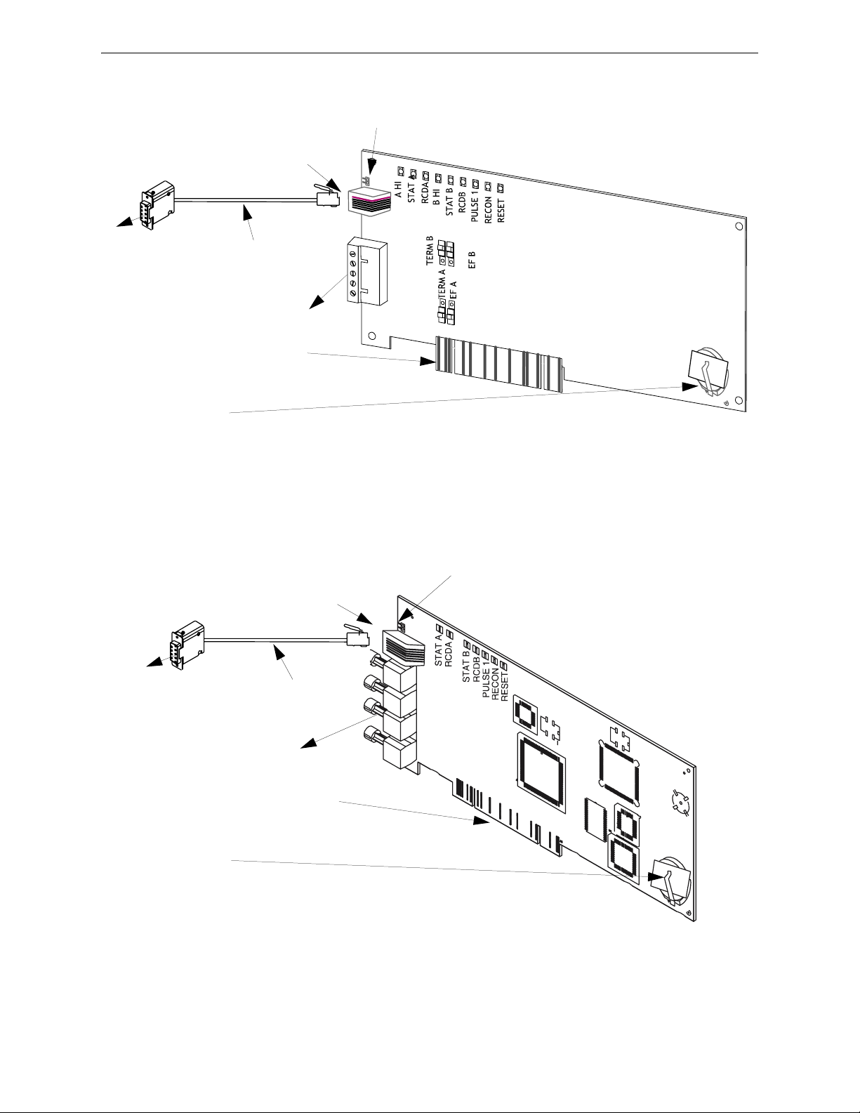
2.2.1 Network Interface Card Layout
This PC board is shipped with a shunt plug over the UPS
SUPV pins. Remove the shunt to write for UPS supervision.
Connect cable to the EIA-232
connector (J2) on the network card.
Connect cable to an
available COM port
Connector Cable
(P/N 75557)
on the Workstation.
NFN Network
Connection
Edge Connector (J5)
insert into a vacant PCI
slot on the Workstation.
Battery
(P/N LITHBATT-3V)
Note:
The NCS-NCW/F is shipped with a paper
strip between the clip and battery. Remove
the paper strip before powering.
Connect cable to the EIA-232
connector (J2) on the network card.
0
1
0
1
Figure 2.1 NFN-GW-PC-W Card Layout
This PC board is shipped with a shunt plug
over the UPS SUPV pins. Remove the
shunt to write for UPS supervision.
Connect cable to
an available
COM port on the
Workstation.
Connector Cable
(P/N 75557)
NFN Network
TX A
RX A
TX B
RX B
Connection
Edge Connector
(J5) insert into a
vacant PCI slot on
the Workstation.
Battery
(P/N LITHBATT-3V)
Note:
The NCS-NCW/F is shipped with a
paper strip between the clip and
battery. Remove the paper strip
before powering.
Figure 2.2 NFN-GW-PC-F Card Layout
14 NFN Gateway Installation & Operation Manual - P/N: 52307:Rev: D 06/01/07
Page 15

About the Network Interface Card Installation NFN Gateway PC Configuration
Network Interface Card LEDs
The following lists the LED indicators and their functions:
Table 2.1 NCS-NCW/F Status LEDs
LED Color Function
A HI Green Channel A High Threshold (NCS-NCW only)
STATA Yellow Channel A inactive for at least 16 seconds
RCDA Green Illuminates to indicate data reception on NFN Network Channel A
B HI Green Channel B High Threshold (NCS-NCW only)
STATB Yellow Channel A inactive for at least 16 seconds
RCDB Green Illuminates to indicate data reception on NFN Network Channel B
PULSE 1 Green Illuminates to indicate data transmission to NFN Network
RECON Yellow Illuminates when NFN Network re-configuration is in progress
RESET Yellow Illuminates to indicate a micro-controller watchdog failure
15NFN Gateway Installation & Operation Manual - P/N: 52307:Rev: D 06/01/07
Page 16

NFN Gateway PC Configuration About the Network Interface Card Installation
2.2.2 Network Interface Card Installation Procedure
Typically the Workstation is ordered with the Network Interface Card already installed. However if
the card is being retrofitted into an existing Workstation computer use the this information as a
guideline to install it.
Step 1. Shut-down the computer, software then hardware.
Step 2. Open the computer’s cover and locate a vacant PCI slot.
Step 3. Remove the blank plate and save the screw from the vacant slot.
Step 4. Insert the Network Interface Card’s edge connector into the vacant PCI slot and then
secure it with the screw.
Step 5. Using the cable (P/N 75557) connect the card’s EIA-232 (J2) connector to the COM port
on the computer.
Step 6. You are now ready to perform "Network Interface Card Cable Connections".
WARNING: ESD
!
These cards contain static sensitive components. Always ground yourself with a proper wrist strap
before handling any circuits so that static charges are removed from the body. Use static-suppressive
packaging to protect electronic assemblies removed from the unit.
16 NFN Gateway Installation & Operation Manual - P/N: 52307:Rev: D 06/01/07
Page 17

About the Network Interface Card Installation NFN Gateway PC Configuration
2.2.3 Network Interface Card Cable Connections
Network Interface Card EIA-232 Connection
The Network Interface Card is connected to an available Workstation Comm Port.
Figure 2.3 Workstation to IP Connection
NFN Network Connection
The Network Interface Card is connected to NFN network through its network port using one of the
following methods:
• NFN-GW-PC-F is the fiber network interface card that is connected to the transmit
(TX)/Receive (RX) pins of one channel to the corresponding pins on the next network
interface card.
• NFN-GW-PC-W is the card that uses a twisted media pair or wires are used for the
connection. One wire connects to one of the CH A pins, the other to the other CH A pin.
When using Style 4 and 7, use CH A and CH B pins. The wires connect to the NFN network.
Figure 2.4 Workstation to NFN Network Connection
17NFN Gateway Installation & Operation Manual - P/N: 52307:Rev: D 06/01/07
Page 18

NFN Gateway PC Configuration NFN Gateway PC Configuration Procedure
2.3 NFN Gateway PC Configuration Procedure
2.3.1 NFN Gateway Settings
NCM Address Setting
Step 1. Start the NFN Gateway PC (Start >NFN Gateway). The NFN Gateway icon is added to
and displays in the Windows System Tray.
Step 2. Double click on the NFN Gateway icon. The NFN Config Tool window displays.
Step 3. Select the highest level entry in the Nodes list column hierarchy.
Figure 2.5 Gateway Node Selection
Step 4. Select File >Login to gain editing control of the selected gateway. The Gateway Login
window displays.
Figure 2.6 Gateway Login Window
Step 5. Type in the gateway password and then click the OK button. The default password is
00000000 (eight zeros). The Property fields now display an asterisk next to the fields that
can be edited.
Step 6. Click in the Value field adjacent to NCM Address Property and then type in the address.
Figure 2.7 NFN Gateway PC NCM Address Setting
Step 7. Now you need to perform “Login Password Settings” on page 19.
18 NFN Gateway Installation & Operation Manual - P/N: 52307:Rev: D 06/01/07
Page 19

NFN Gateway PC Configuration Procedure NFN Gateway PC Configuration
About the NFN Gateway Mode Setting
Figure 2.8 NFN Gateway PC Mode Setting
The NFN Gateway PC’s operation mode matches the mode that has been selected using the
Configuration Tool’s System Options functionality. Refer to the Workstation or Configuration Tool
manuals for information about selecting these modes:
Supervising Station Mode Refer to the Workstation manual for a “Proprietary Supervising
Station Mode Overview”.
FCC and FCC+DCC Mode Refer to the Workstation manual for a “Fire Command Center
(FCC) Mode Overview (PPU)”.
NOTE: You can only select the FCC and FCC+DCC modes if you only have one NFN gateway
connected to the Workstation. Those modes are not available with multiple NFN gateways or if
any other type of gateway is configured for your system.
2.3.2 Login Password Settings
The first time the gateway is started the factory default password is used (00000000 - eight zeros),
after the initial configuration it is highly recommended that you can the password.
Step 1. Select Tools >Set Gateway Password. The Gateway Login (change password) window
displays.
Figure 2.9 Gateway Login - Change Password
Step 2. Type in the current password in the Password field.
• Passwords are case-sensitive.
• Alpha and numeric characters are supported.
• 1 character minimum and 8 character maximum.
Step 3. Type in a new password in the New Password field.
Step 4. Type in the new password again in the Re-Enter New Password field.
Step 5. Click the OK button to complete the password change.
You have completed "NFN Gateway PC Configuration".
19NFN Gateway Installation & Operation Manual - P/N: 52307:Rev: D 06/01/07
Page 20

NFN Gateway PC Configuration NFN Gateway PC Configuration Procedure
20 NFN Gateway Installation & Operation Manual - P/N: 52307:Rev: D 06/01/07
Page 21

Section 3 NFN Config Tool Reference Information
3.1 NFN Config Tool Description
The NFN Config Tool interface is used to display configuration information about NFN network
and the NFN Gateway. With the appropriate access level a user can view and/or change the
gateways settings and security.
The NFN Config Tool uses an Windows Explorer-style collapsible/expandable Nodes list. The
PROPERTY/VALUE columns display information about the selection made in the Nodes list
Property fields that are preceded with an asterisk mean the Value adjacent to it can be modified in
some way.
3.2 Property/Value Field Descriptions
The NFN Config Tool window displays configuration information about the gateway and the NFN
network the gateway is monitoring. When logged into the gateway using a password you can
change settings for any field that has asterik (*) preceding the field’s name.
Figure 3.1 NFN Gateway PC Property and Values
• Version - Displays the gateway’s version.
3.2.1 GATEWAY SETTINGS Fields
• Gateway Label - The name entered will only display on the NFN Network.
• Mode - Displays the NFN Gateway mode which is configured through the Configuration Tool.
This field can not be configured through the NFN Config Tool for this gateway type.
• NCM Address - Is used to set the node address of the NFN Gateway.
• Trouble Reminder - If set to True a trouble reminder message is issued across the network
every 24 hours at 11:00 AM; if there is an active trouble on that network.
• Audio - Is used to enable the audio option if installed.
• Channel A and Channel B Threshold - Are set according to the determined amount of network
noise that is present in the network", the threshold is determined by the distance of the network
segment. Refer to NFN manual for details. High is used when the most noise is present and
filter that noise accordingly.
• Style 7 - If set to True Style 7 is used, if set to False Style 4 is used.
• COMM Port - Is used to specify which port the NFN Gateway uses to communicate with
NCM.
21NFN Gateway Installation & Operation Manual - P/N: 52307:Rev: D 06/01/07
Page 22

NFN Config Tool Reference Information Property/Value Field Descriptions
3.2.2 Panel Properties Fields
Figure 3.2 NFN Config Tool Panel Property/Value Field Descriptions
Node - Is used to change the NFN network address of the panel.
VERSIONS
If the NCM Version field is displayed in red, then the version doesn’t match the Local Node entry.
NOTE: The NCM version for panel must match the NCM version displayed in the Local Node
entry. When it does not match the non-matching version is displayed as a red entry. Contact
Technical Services for assistance in acquiring the correct version.
22 NFN Gateway Installation & Operation Manual - P/N: 52307:Rev: D 06/01/07
Page 23

Menu Descriptions NFN Config Tool Reference Information
3.3 Menu Descriptions
3.3.1 File
• Login... - Is used to gain editing control over the gateway. The factory default password is
00000000 (eight zeros). Refer to “Login Password Settings” on page 19.
• Reboot Gateway - Restarts the gateway on its NFN network.
• Exit - Closes the NFN Config Tool window.
3.3.2 View
All these choices display read only information windows, no editing can be done on the
information displayed from these windows.
• Refresh Gateway List - Used to generate a new list of gateways that will be available and
displayed when the NFN Config Tool’s Address field down arrow is clicked.
• Refresh Nodes List - Used to ping the nodes connected to the current gateway and display their
information.
• Node Table - Displays all the nodes connected to the gateway and their respective version
information.
NOTE: The NCM version for panel must match the NCM version displayed in the Local Node
entry. When it does not match the non-matching version is displayed as a red entry. Contact
Technical Services for assistance in acquiring the correct version. Also panels that do not use an
NCM are displayed as a red entry.
CAUTION: NCM Version
!
NCM versions that do not match will result in an unstable NFN network.
• Connected Clients - Used to display a window which lists the clients that are connected to the
gateway.
3.3.3 Tools
Some menu choices are only displayed when a relative selection is made in Nodes list column.
Right click options are also available for the selection made in the Nodes list column.
• Delete Node - Is used to remove a node from the gateway. The Node must be offline before it
can be deleted.
• Auto Detect Nodes - Is used to force the gateway to detect nodes on the NFN network. The
gateway searches for all online nodes on the NFN network.
• Set Gateway Password - Refer to “Login Password Settings” on page 19.
3.3.4 Help
• About - Display version information.
23NFN Gateway Installation & Operation Manual - P/N: 52307:Rev: D 06/01/07
Page 24

NFN Config Tool Reference Information Menu Descriptions
24 NFN Gateway Installation & Operation Manual - P/N: 52307:Rev: D 06/01/07
Page 25

Index
A
Architecture
Gateway System
Audio
21
8
C
Channel A Threshold 21
Channel B Threshold
COMM Port
Configuration Tool
21
installation
21
13
D
Documentation 12
E
Ethernet Network
about
9
F
File menu
descriptions
23
L
listed for the purpose 9
N
NCM Address 21
P
Proprietary Supervising Station 9
S
Style 7 21
T
Tools menu
descriptions
Trouble Reminder
23
21
U
ULC 9
Uninterruptable Power Supply (UPS) Supervision
11
G
Gateway
assembly
configuration
Configuration Procedure
mode
multiple
PC board LEDs
product description
Required Equipment
Gateway Config Tool
field descriptions
Gateway Label
Gateway PC board
layout
Gateway System Architecture
13
13
19
13
15
7
13
21
21
14
H
Help menu
descriptions
23
I
Installation
Environmental Conditions
18
8
12
V
View menu
descriptions
23
25NFN Gateway - P/N: 52307:Rev: D 06/01/07
Page 26

Index
26 NFN Gateway - P/N: 52307:Rev: D 06/01/07
Page 27

Limited Warranty
Honeywell International Inc. warrants products manufactured by
it to be free from defects in materials and workmanship for
eighteen (18) months from the date of manufacture, under normal
use and service. Products are date stamped at time of
manufacture. The sole and exclusive obligation of Honeywell
International Inc. is to repair or replace, at its option, free of charge
for parts and labor, any part that is defective in materials or
workmanship under normal use and service. All returns for credit
are subject to inspection and testing at the factory before actual
determination is made to allow credit. Honeywell International
Inc. does not warrant products not manufactured by it, but assigns
to the purchaser any warranty extended by the manufacturer of
such products. This warranty is void if the product is altered or
repaired by anyone other than Honeywell International Inc. or as
expressly authorized by Honeywell International Inc. in writing, or
is serviced by anyone other than Honeywell International Inc. or
its authorized distributors. This warranty is also void if there is a
failure to maintain the products and systems in which they operate
in a proper and workable manner. In case of defect, secure a
Return Material Authorization form from our Return Authorization
Department.
This writing constitutes the only warranty made by Honeywell
International Inc., with respect to its products. Honeywell
International Inc., does not represent that its products will prevent
any loss by fire or otherwise, or that its products will in all cases
provide the protection for which they are installed or intended.
Buyer acknowledges that Honeywell International Inc., is not an
insurer and assumes no risk for loss or damages or the cost of any
inconvenience, transportation damage, misuse, abuse, accident or
similar incident.
HONEYWELL INTERNATIONAL INC. GIVES NO WARRANTY,
EXPRESS OR IMPLIED, OF MERCHANTABILITY, FITNESS FOR
ANY PARTICULAR PURPOSE, OR OTHERWISE WHICH
EXTENDS BEYOND THE DESCRIPTION ON THE FACE
HEREOF. UNDER NO CIRCUMSTANCES SHALL HONEYWELL
INTERNATIONAL INC. BE LIABLE FOR ANY LOSS OF OR
DAMAGE TO PROPERTY, DIRECT, INCIDENTAL OR
CONSEQUENTIAL, ARISING OUT OF THE USE OF, OR
INABILITY TO USE HONEYWELL INTERNATIONAL INC.’S
PRODUCTS. FURTHERMORE, HONEYWELL INTERNATIONAL
INC. SHALL NOT BE LIABLE FOR ANY PERSONAL INJURY OR
DEATH WHICH MAY ARISE IN THE COURSE OF, OR AS A
RESULT OF, PERSONAL, COMMERCIAL OR INDUSTRIAL USE
OF ITS PRODUCTS.
27ONYXWorks® Workstation - Installation & Operation Manual - P/N: 52307:Rev: D 06/01/07
Page 28

World Headquarters
12 Clintonville Road
Northford, CT 06472-1610 USA
203-484-7161
fax 203-484-7118
www.notifier.com
 Loading...