


P/N 51990:A2 ECN 03-340
NOTI•FIRE•NET™NOTI•FIRE•NET™
NOTI•FIRE•NET™ Web Server
NOTI•FIRE•NET™NOTI•FIRE•NET™
Installation/Operation Manual
www.PDF-Zoo.com
Document 51990
12/02/03 Rev:
A2

Fire Alarm System Limitations
While a fire alarm system may lower insurance rates, it is not a substitute for fire insurance!
An automatic fire alarm system–typically made up of smoke
detectors, heat detectors, manual pull stations, audible warning devices, and a fire alarm control with remote notification
capability–can provide early warning of a developing fire.
Such a system, however, does not assure protection against
property damage or loss of life resulting from a fire.
The Manufacturer recommends that smoke and/or heat detectors be located throughout a protected premise following the
recommendations of the current edition of the National Fire
Protection Association Standard 72 (NFPA 72),
manufacturer's recommendations, State and local codes, and
the recommendations contained in the Guide for Proper Use
of System Smoke Detectors, which is made available at no
charge to all installing dealers. A study by the Federal Emergency Management Agency (an agency of the United States
government) indicated that smoke detectors may not go off in
as many as 35% of all fires. While fire alarm systems are designed to provide early warning against fire, they do not guarantee warning or protection against fire. A fire alarm system
may not provide timely or adequate warning, or simply may
not function, for a variety of reasons:
Smoke detectors may not sense fire where smoke cannot
reach the detectors such as in chimneys, in or behind walls,
on roofs, or on the other side of closed doors. Smoke detectors also may not sense a fire on another level or floor of a
building. A second-floor detector, for example, may not sense
a first-floor or basement fire.
Particles of combustion or "smoke" from a developing fire
may not reach the sensing chambers of smoke detectors because:
• Barriers such as closed or partially closed doors, walls, or
chimneys may inhibit particle or smoke flow.
• Smoke particles may become "cold," stratify, and not reach
the ceiling or upper walls where detectors are located.
• Smoke particles may be blown away from detectors by air
outlets.
• Smoke particles may be drawn into air returns before reaching the detector.
The amount of "smoke" present may be insufficient to alarm
smoke detectors. Smoke detectors are designed to alarm at
various levels of smoke density. If such density levels are not
created by a developing fire at the location of detectors, the
detectors will not go into alarm.
Smoke detectors, even when working properly, have sensing
limitations. Detectors that have photoelectronic sensing
chambers tend to detect smoldering fires better than flaming
fires, which have little visible smoke. Detectors that have ionizing-type sensing chambers tend to detect fast-flaming fires
better than smoldering fires. Because fires develop in different ways and are often unpredictable in their growth, neither
type of detector is necessarily best and a given type of detector may not provide adequate warning of a fire.
Smoke detectors cannot be expected to provide adequate
warning of fires caused by arson, children playing with
matches (especially in bedrooms), smoking in bed, and violent
explosions (caused by escaping gas, improper storage of
flammable materials, etc.).
Heat detectors do not sense particles of combustion and
alarm only when heat on their sensors increases at a predetermined rate or reaches a predetermined level. Rate-of-rise
heat detectors may be subject to reduced sensitivity over time.
For this reason, the rate-of-rise feature of each detector
should be tested at least once per year by a qualified fire protection specialist.
Heat detectors are designed to protect
property, not life.
IMPORTANT!
Smoke detectors must be installed in the
same room as the control panel and in rooms used by the system for the connection of alarm transmission wiring, communications, signaling, and/or power.
cated, a developing fire may damage the alarm system, crippling its ability to report a fire.
Audible warning devices such as bells may not alert people
if these devices are located on the other side of closed or
partly open doors or are located on another floor of a building.
Any warning device may fail to alert people with a disability or
those who have recently consumed drugs, alcohol or medication. Please note that:
• Strobes can, under certain circumstances, cause seizures
in people with conditions such as epilepsy.
• Studies have shown that certain people, even when they
hear a fire alarm signal, do not respond or comprehend the
meaning of the signal. It is the property owner's responsibility to conduct fire drills and other training exercise to make
people aware of fire alarm signals and instruct them on the
proper reaction to alarm signals.
• In rare instances, the sounding of a warning device can
cause temporary or permanent hearing loss.
A fire alarm system will not operate without any electrical
power. If AC power fails, the system will operate from standby
batteries only for a specified time and only if the batteries
have been properly maintained and replaced regularly.
Equipment used in the system may not be technically compatible with the control. It is essential to use only equipment
listed for service with your control panel.
Telephone lines needed to transmit alarm signals from a
premise to a central monitoring station may be out of service
or temporarily disabled. For added protection against telephone line failure, backup radio transmission systems are recommended.
The most common cause of fire alarm malfunction is inadequate maintenance. To keep the entire fire alarm system in
excellent working order, ongoing maintenance is required per
the manufacturer's recommendations, and UL and NFPA standards. At a minimum, the requirements of Chapter 7 of NFPA
72 shall be followed. Environments with large amounts of
dust, dirt or high air velocity require more frequent maintenance. A maintenance agreement should be arranged
through the local manufacturer's representative. Maintenance
should be scheduled monthly or as required by National and/
or local fire codes and should be performed by authorized professional fire alarm installers only. Adequate written records
of all inspections should be kept.
If detectors are not so lo-
Precau-L-4-2002.p65
www.PDF-Zoo.com
NFN Web Server User’s Manual PN 51990:A2 12/02/032

Installation Precautions
Adherence to the following will aid in problem-free installation with long-term reliability:
WARNING -
nected to the fire alarm control panel.
of power before servicing. Control unit and associated equipment may be damaged by removing and/or inserting cards,
modules, or interconnecting cables while the unit is energized.
Do not attempt to install, service, or operate this unit until this
manual is read and understood.
CAUTION -
Changes.
must be tested in accordance with NFPA 72 Chapter 7 after
any programming operation or change in site-specific software. Reacceptance testing is required after any change, addition or deletion of system components, or after any modification, repair or adjustment to system hardware or wiring.
All components, circuits, system operations, or software functions known to be affected by a change must be 100% tested.
In addition, to ensure that other operations are not inadvertently affected, at least 10% of initiating devices that are not
directly affected by the change, up to a maximum of 50 devices, must also be tested and proper system operation verified.
This system meets NFPA requirements for operation at
0-49° C/32-120° F
per ULC - (non-condensing) at 30° C/86° F. However, the
useful life of the system's standby batteries and the electronic
components may be adversely affected by extreme temperature ranges and humidity. Therefore, it is recommended that
this system and all peripherals be installed in an environment
with a nominal room temperature of 15-27° C/60-80° F.
Verify that wire sizes are adequate for all initiating and
indicating device loops. Most devices cannot tolerate more
than a 10% I.R. drop from the specified device voltage.
Several different sources of power can be con-
Disconnect all sources
System Reacceptance Test after Software
To ensure proper system operation, this product
and at a relative humidity of 85% RH - 93%
Like all solid state electronic devices, this system may
operate erratically or can be damaged when subjected to lightning-induced transients. Although no system is completely
immune from lightning transients and interferences, proper
grounding will reduce susceptibility.
Overhead or outside
aerial wiring is not recommended, due to an increased susceptibility to nearby lightning strikes.
cal Services Department if any problems are anticipated or
encountered.
Disconnect AC power and batteries prior to removing or inserting circuit boards. Failure to do so can damage circuits.
Remove all electronic assemblies prior to any drilling, filing,
reaming, or punching of the enclosure. When possible, make
all cable entries from the sides or rear. Before making modifications, verify that they will not interfere with battery, transformer, and printed circuit board location.
Do not tighten screw terminals more than 9 in-lbs.
Over-tightening may damage threads, resulting in reduced
terminal contact pressure and difficulty with screw terminal
removal.
Though designed to last many years, system components
can fail at any time. This system contains static-sensitive
components. Always ground yourself with a proper wrist strap
before handling any circuits so that static charges are removed from the body. Use static-suppressive packaging
to protect electronic assemblies removed from the unit.
Follow the instructions in the installation, operating, and
programming manuals. These instructions must be followed
to avoid damage to the control panel and associated
equipment. FACP operation and reliability depend upon
proper installation by authorized personnel.
Consult with the Techni-
FCC Warning
WARNING: This equipment generates, uses, and can radi-
ate radio frequency energy and if not installed and used in
accordance with the instruction manual, may cause interference to radio communications. It has been tested and
found to comply with the limits for class A computing device
pursuant to Subpart B of Part 15 of FCC Rules, which is
designed to provide reasonable protection against such
interference when operated in a commercial environment.
Operation of this equipment in a residential area is likely to
cause interference, in which case the user will be required
to correct the interference at his own expense.
Canadian Requirements
Acclimate Plus™, HARSH™, NOTI•FIRE•NET™, ONYX™, and VeriFire™ are trademarks, and FlashScan® and VIEW® are registered trademarks of NOTIFIER.
NION™ and UniNet® are trademarks of NIS. NIS™ and Notifier Integrated Systems™ are trademarks and NOTIFIER® is a registered trademark of Fire•Lite Alarms,
Inc. Echelon® is a registered trademark and LonWorks™ is a trademark of Echelon Corporation. ARCNET® is a registered trademark of Datapoint Corporation.
Microsoft® and Windows® are registered trademarks of the Microsoft Corporation. LEXAN® is a registered trademark of GE Plastics, a subsidiary of General Electric
Company.
NFN Web Server User’s Manual PN 51990:A2 12/02/03 3
www.PDF-Zoo.com
This digital apparatus does not exceed the Class A
limits for radiation noise emissions from digital
apparatus set out in the Radio Interference Regulations of
the Canadian Department of Communications.
Le present appareil numerique n'emet pas de bruits radioelectriques depassant les limites applicables aux appareils
numeriques de la classe A prescrites dans le Reglement
sur le brouillage radioelectrique edicte par le ministere des
Communications du Canada.
Precau-L-4-2002.p65

Table of Contents
SECTION ONE: NFN WEB SERVER FEATURES ...................................................................... 7
1.1 PRODUCT DESCRIPTION ............................................................................................................................ 7
1.2 NFN WEB SERVER/SERIAL CONFIGURATION TOOL FEATURES.................................................................. 7
1.3 RELATED DOCUMENTATION ...................................................................................................................... 7
Table 1.3-1: Related Documentation .................................................................................................................... 7
1.4 STANDARDS AND SPECIFICATIONS .............................................................................................................. 8
1.5 COMPATIBILITY ........................................................................................................................................ 8
1.6 SYSTEM REQUIREMENTS ........................................................................................................................... 8
1.7 SYSTEM ARCHITECTURE ........................................................................................................................... 9
Figure 1.7-1: NFN Web Server Network Architecture ......................................................................................... 9
Figure 1-7.2: NFN Web Server PPP Architecture............................................................................................... 10
Figure 1-7.3: NFN Web Server Direct Panel Interface Architecture ...................................................................11
SECTION TWO: NFN WEB SERVER HARDWARE INSTALLATION ................................. 13
2.1 REQUIRED COMPONENTS ........................................................................................................................ 13
2.2 INSTALLATION OVERVIEW ...................................................................................................................... 14
Figure 2.2-1: NFN Web Server Assembly Checklist .......................................................................................... 14
2.3 INSTALLING THE NFN WEB SERVER ASSEMBLY INTO A CAB-4 SERIES CABINET .................................... 15
Figure 2.3-1: NFN Web Server Installation Diagram ......................................................................................... 15
2.4 NFN WEB SERVER PC BOARD LAYOUT ................................................................................................15
Figure 2.4-1: PC Board Layout ........................................................................................................................... 15
2.5 POWER SUPPLY CONNECTIONS ............................................................................................................... 16
Figure 2.5-1: 46175 Power Supply Specifications ............................................................................................. 16
Figure 2.5-2: NFN Web Server Power Connection ............................................................................................ 16
Figure 2.5-3: NWS Power Supply Connections for Direct Panel Interfacing .................................................... 17
2.6 DB-9 TO NUP CONNECTION (NFN WEB SERVER TO NCM-W/F OR NUP DIRECT CONNECT) ............. 18
Figure 2.6-1: DB-9 to NUP Connection ............................................................................................................. 18
2.7 MODEM CONNECTION (NFN WEB SERVER TO MODEM) ........................................................................ 18
Figure 2.7-1: 10-Pin to DB-9 Connection (Modem Connection) ....................................................................... 18
2.8 ETHERNET NETWORK CONNECTION ....................................................................................................... 19
Figure 2.8-1: Ethernet Connection ...................................................................................................................... 19
2.9 PC TO PC CONNECTION ........................................................................................................................ 19
Figure 2.9-1: PC to PC Serial Connection .......................................................................................................... 19
SECTION THREE: NFN WEB SERVER CONFIGURATION ................................................. 21
3.1 NFN WEB SERVER SERIAL CONFIGURATION TOOL INSTALLATION.......................................................... 21
3.2 USING THE NWS CONFIGURATION TOOL FOR CONFIGURATION .............................................................. 21
Figure 3.2-1: NFN Web Server Serial Setup Dialog ........................................................................................... 21
Figure 3.2-2: NFN Web Server Configuration ................................................................................................... 22
3.3 USING VERI•FIRE™ TOOLS FOR CONFIGURATION .................................................................................. 23
Figure 3.3-1: Serial Port Configuration Utility ................................................................................................... 23
3.4 INITIAL SETUP OF THE NFN WEB SERVER ............................................................................................. 24
Figure 3.4-1: Veri•Fire™ Local Connection Type .............................................................................................. 24
Figure 3.4-2: Nodes Screen ................................................................................................................................ 24
Figure 3.4-3: NFN Web Server Configuration Settings ...................................................................................... 25
Figure 3.4-4: Selecting the Connection Type ...................................................................................................... 26
Figure 3.4-5: Configuring the Web Server Connection Session ......................................................................... 26
Figure 3.4-6: Veri•Fire™ Tools System Password ............................................................................................. 27
Figure 3.4-7: Selecting the Connection Type ...................................................................................................... 27
Figure 3.4-8: Changing the Node Address.......................................................................................................... 28
Figure 3.4-9: Changing the Node Address.......................................................................................................... 28
www.PDF-Zoo.com
NFN Web Server User’s Manual PN 51990:A2 12/02/034

SECTION FOUR: NFN WEB SERVER OPERATION .............................................................. 29
4.1 NFN WEB SERVER SECURITY ................................................................................................................29
Figure 4.1-1: NFN Web Server Login Dialog ..................................................................................................... 29
4.2 THE BROWSER INTERFACE ..................................................................................................................... 29
Figure 4.2-1: NWS Home Page .......................................................................................................................... 29
4.3 SYSTEM ADMINISTRATION ....................................................................................................................... 30
4.3.1 Auto Detect Points on all Panels ................................................................................................................. 30
Figure 4.3.1-1: Auto Detect Points ..................................................................................................................... 30
Figure 4.3.1-2: Auto Point Detect AFP400 Message .......................................................................................... 31
Figure 4.3.1-3: Auto Detect Screen .................................................................................................................... 31
4.3.2 E-mail Notification ....................................................................................................................................... 32
Figure 4.3.2-1: E-mail Configuration ................................................................................................................. 32
Figure 4.3.2-2: E-mail Profile Configuration ..................................................................................................... 33
Figure 4.3.2-3: Email Configuration - Custom Messages .................................................................................. 34
Figure 4.3.2-4: Sample Email Message .............................................................................................................. 34
4.3.3 System Settings ............................................................................................................................................. 35
Figure 4.3.3-1 System Settings ........................................................................................................................... 35
4.3.4 Monitoring Profiles ...................................................................................................................................... 36
Figure 4.3.4-1: Monitoring Profiles .................................................................................................................... 36
4.3.5 Node Mapping .............................................................................................................................................. 37
Figure 4.3.5-1: Node Mapping............................................................................................................................ 37
4.3.6 Password Configuration .............................................................................................................................. 38
Figure 4.3.6-1: User Configuration..................................................................................................................... 38
4.3.7 Authorization Log ........................................................................................................................................ 39
Figure 4.3.7-1: Authorization Log ...................................................................................................................... 39
4.4 MULTIPLE EVENT LIST .......................................................................................................................... 40
Figure 4.4-1: Event List Summary ...................................................................................................................... 40
Figure 4.4-2: Multiple Event List Details ........................................................................................................... 41
4.5 VERSION INFORMATION .......................................................................................................................... 42
Figure 4.5-1: Version Information ...................................................................................................................... 42
4.6 NUP PORT STATISCTICS ........................................................................................................................ 43
Figure 4.6-1: NUP Port Statisctics Overview ..................................................................................................... 43
Figure 4.6-2: Local Node NUP Port Statisctics .................................................................................................. 43
4.7 SCREEN DETAILS AND OPTIONS FOR SPECIFIC PANELS ............................................................................ 44
Figure 4.7-1: Panel Properties Display Sample .................................................................................................. 44
Figure 4.7-2: Loop Properties Sample Screen .................................................................................................... 45
Figure 4.7-3: Module Properties Sample Screen ................................................................................................ 45
Figure 4.7-4: Detector Properties Sample Screen ............................................................................................... 46
INDEX ............................................................................................................................................... 47
NFN Web Server User’s Manual PN 51990:A2 12/02/03 5
www.PDF-Zoo.com

NOTES
www.PDF-Zoo.com
NFN Web Server User’s Manual PN 51990:A2 12/02/036

SECTION ONE: NFN WEB SERVER FEATURES
1.1 P
RODUCT DESCRIPTION
The NOTI•FIRE•NET™ Web Server is a web-based device that acts as an HTML server that allows remote access
to the NOTI•FIRE•NET™ network via the Internet or an Intranet. With the NFN Web Server interface, the user can
view the history of a fire alarm control panel (FACP), event status, device properties, and other information based on
access permissions defined by the system administrator. All data available on the web server is a “snapshot” of the data
on the NOTI•FIRE•NET™ network at the time the browser requested the information. The NFN Web Server
communicates to NOTI•FIRE•NET™ version 5.0 and later. The NFN Web Server interfaces to the Internet/Intranet
using an IP-based wire Ethernet connection or through a direct dial-up connection using a modem. The Serial Configuration Tool allows you to make the necessary network configuration settings for the web server to be able to communicate with the browser.
1.2 NFN WEB SERVER/SERIAL CONFIGURATION TOOL FEATURES
Below are some of the features of the NFN Web Server and Serial Configuration Tool
• Ability to access NOTI•FIRE•NET™ device and system statuses and properties remotely via the Internet,
Intranet or direct dial-up connection.
• Compatible with NOTI•FIRE•NET™ version 5.0 and later
• Serial Configuration Tool runs on any laptop or PC using Windows™ and having an open COM port
• One web server supports multiple users
• Standard IP over Ethernet connection
• Up to 128 user accounts are supported
• Built-in password security and user access record
• Supports standard Microsoft® Internet Explorer 5
• Intuitive Explorer user interface
• Sends up to 50 emails in response to any system event
1.3 RELATED DOCUMENTATION
Below is a list of NOTI•FIRE•NET™ related documentation.
For i nformation on… Re fe r t o… Pa rt No.
Compatible Devices Device Compatibility Document 15378
Cabinets & Chassis CAB-3/CAB-4 Series Installation Document 15330
Auxiliary Power Supplies
& Battery Chargers
Offline Programming
Utility
VeriFire-TCDNetworking
Panels and Annunci ators
ACPS-2406 Installation Manual 51304
Veri•Fire™ Tools on-line help file
Veri•Fire™ Medium Systems on-line help file
Veri•Fir e™ Tools CD Insert
Noti•Fire•Net™ Manual
NCM-W/F Installati on Document
MIB Media Interface Board
NCS Network Contr ol S tation
NCA Networ k Control Annunciator
BACnet Gateway
NFS-640 Installation/Operation/Pr ogramming manuals
NFS-3030 Installation/Operation/Programming manuals
Networ k Control Annunciator ( NCA)
Network Co ntrol Station (NCS)
AFP-200 Ins truction manual
AFP-300/400 Installation/Operation/Programming manuals
AM2020/AFP 1010 Installation/Operation/Programming manuals
UniNet Online Instruction Manual
VeriFire-TCD
VeriFire-CD
518 71
515 84
515 33
502 55
510 95
514 82
516 59
51332/51334/51333
51330/51344/51345
514 82
510 95
15 511
50253/50260/50259
15088
519 94
NFN Web Server User’s Manual PN 51990:A2 12/02/03 7
www.PDF-Zoo.com
Table 1.3-1: Related Documentation

1.4 STANDARDS AND SPECIFICATIONS
The NFN Web Server has been designed to comply with standards set forth by the following regulatory agencies:
• Underwriters Laboratories Standard UL 864
• NFPA 72 National Fire Alarm Code
• CAN/ULC - S527-M99 Standard for Control Units for Fire Alarm Systems
• UL-1076 Proprietary Burglar Alarm Units and Systems.
The contents of this manual are important and must be kept in close proximity of the hardware. If building ownership
is changed, this manual and all other testing and maintenance information must also be passed to the current owner of
the facility. A copy of this manual was shipped with the equipment and is also available from the manufacturer.
WARNING: Improper installation, maintenance, or lack of routine testing could result in system malfunction.
1.5 COMPATIBILITY
The NFN Web Server is compatible with NOTI•FIRE•NET™ version 5.0 and later of the following panels and
devices:
• NFS-640 (version 2.0, NCM-W/F)
• NFS-3030 (version 2.0, NCM-W/F)
• AM2020 (version 5.0 SIB)
• AFP-1010 (version 5.0 SIB)
• AFP-200 (version 5.0, NAM, events only)
• AFP-300/400 (version 5.0, NAM)
• BACnet Gateway (version 2.0, events only)
• NFN NION (events only)
• Network Control Station (NCS, version 3.0, events only)
• Network Control Annunciator (NCA, version 2.0, NCM-W/F, events only)
!
NOTES: The NFN Web Server is not
intended as a primary annunciator and
is ancillary in nature.
No NCM is required when the NFN Web
Server connects directly to an NFS-640
and NFS-3030.
1.6 SYSTEM REQUIREMENTS
BROWSER
• Microsoft® Internet Explorer version 5.0 or later, running on Windows 98® or Windows 2000®
NOTE: Netscape® is not supported by the NFN Web
!
Server application.
VERI•FIRE™ TOOLS/SERIAL CONFIGURATION TOOL
• Windows 2000® operating system
NOTE: The NFN Web Server is
!
DIAL-UP MODEM CONNECTION
• Serial modem with minimum capability of 57.6K baud
compatible with Veri•Fire™ Tools
version 3.00 or later.
NFN Web Server User’s Manual PN 51990:A2 12/02/038
www.PDF-Zoo.com
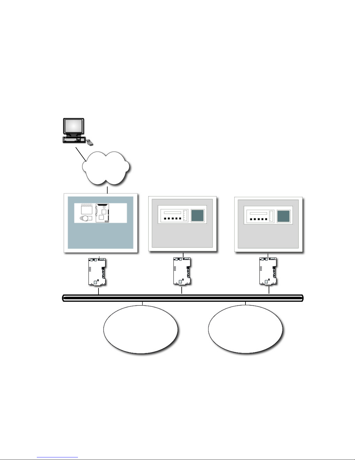
1.7 SYSTEM ARCHITECTURE
There are three network options for the NFN Web Server:
• Internet or Intranet connection
• Using a dial-up modem
• Direct panel interface to an NFS-640 or NFS-3030
The following diagrams show architecture options for a system using the NFN Web Server.
INTERNET/INTRANET CONNECTION
The NFN Web Server can uses an Internet/Intranet connection via IP over Ethernet.
PC Browser
Interface
Internet or
Intranet
NWS
NCM-W/F
NOTI•FIRE•NET™
Figure 1.7-1: NFN Web Server Network Architecture
FACP
NCS
UniNet®/NFN NION
BACnet Gateway
FACP
NCS
UniNet®/NFN NION
BACnet Gateway
NFN Web Server User’s Manual PN 51990:A2 12/02/03 9
www.PDF-Zoo.com

NFN WEB SERVER DIALUP CONNECTION
The NFN Web Server can use a serial modem to communicate with a remote browser via telephone lines.
PC Browser
NWS
modem
supplied by
customer
Interface
NCM-W/F
NOTI•FIRE•NET™ network
Figure 1-7.2: NFN Web Server PPP Architecture
NOTES: Only one user can dial into the server at a time.
!
The server can support an intranet/internet connection
simultaneously with a dialup connection.
www.PDF-Zoo.com
NFN Web Server User’s Manual PN 51990:A2 12/02/0310

NFN WEB SERVER INTERFACE TO STANDALONE PANEL (NFS-640 OR NFS-3030)
The NFN Web Server can directly interface with an NFS-640 or NFS-3030 panel to connect them via Internet/Intranet
to a PC browser. A DB-9-to-NUP cable is used to make the connection.
PC Browser
Interface
Internet,
Intranet or
The NWS connects directly to
an NFS-640 or NFS-3030 via a
DB9 - NUP cable.
Dial-Up
NFS-640
or
NFS-3030
NWS
NOTE: No NCM is required when the NWS
!
connects directly to an NFS-640 or NFS-3030.
Figure 1-7.3: NFN Web Server Direct Panel Interface Architecture
NFN Web Server User’s Manual PN 51990:A2 12/02/03 11
www.PDF-Zoo.com

NOTES
www.PDF-Zoo.com
NFN Web Server User’s Manual PN 51990:A2 12/02/0312

SECTION TWO: NFN WEB SERVER HARDWARE INSTALLATION
2.1 R
The NFN Web Server requires the following equipment:
NFN Web Server Assembly:
Network Interface (sold separately):
Cabinetry/Installation Hardware (sold separately):
EQUIRED COMPONENTS
NOTE: The NWS is for ancillary use only and
does not increase the burglary grade of service
!
• PC board (P/N 46173) for the NFN Web Server
• Power supply (P/N 46175) - 24VDC to 5VDC
• PNET-1 surge suppressor
• CAT5 cable (P/N 75585) - provides Ethernet connection cable between NFN Web Server PC board and PNET1 surge suppressor
• DB9 to NUP Cable (P/N 75554) - connects the NFN Web Server to an NCM-W/F
• Modem cable - connects the Web Server to a modem (see Figure 2.7-1)
• NUP to 24V power cable (P/N 75583) - provides power for the NCM-W/F (not required for standalone mode)
• HDD Power connector (P/N 75581) - used for 24VDC to 5VDC power connection
• Serial Configuration Tool software (supplied on CD-ROM, P/N NWS-SW)
• NFN Web Server/Power Supply Mounting Plate (P/N 18541)
• NCM-W/F Network Communications Module - used to facilitate network communication between the NFN
Web Server and NOTI•FIRE•NET™. NOTE: The NCM-W/F is not required when directly connecting an
NFN Web Server to an NFS-640 or NFS-3030 when either acts as a standalone panel.
• CAB-3/CAB-4 series cabinet
• CHS-4L chassis
for the system.
Other Required Equipment (NOTE: These items must be supplied by the customer.):
• PC to PC connector cable - connects the NFN Web Server to a PC or laptop.
• PC or notebook - used to configure the NFN Web Server.
NFN Web Server User’s Manual PN 51990:A2 12/02/03 13
www.PDF-Zoo.com
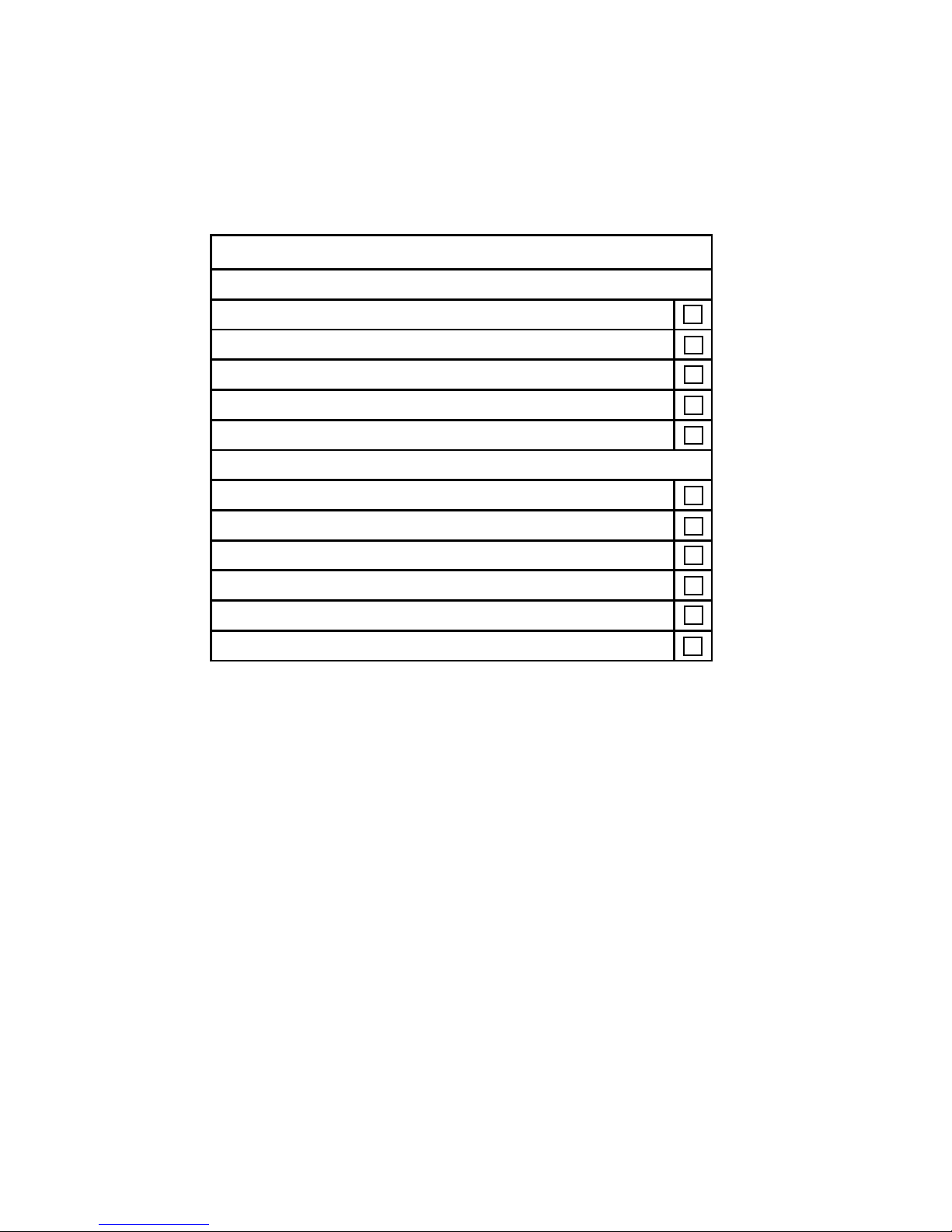
2.2 INSTALLATION OVERVIEW
Use the following checklist as a guideline for assembling the hardware and making necessary cable connections. The
sections that follow provide details on making these connections.
NFN Web Browser Assembly Checklist
Hardware Assembly
Install NFN Web Server PC board onto mounting plate
Install power supply onto mounting plate
Install PNET-1 onto mounting plate
Install mounted NFN Web Server assembly into cabinet
Install NCM-W/F - not required for direct connection
Cable Connections
Web Server serial connection to NCM-W/F or panel CPU (P/N 75554)
Web Server power co nnection (P/N 75581)
Web Server network connection
PNET-1 surge suppressor connection (P/N 75585)
NCM -W/F power conn ection (P/N 75583) - not requ ired for di rect connecti on
NCM-W/F data connection
Figure 2.2-1: NFN Web Server Assembly Checklist
CAUTION: Different sources of power are used in conjunction with the NFN Web Server product. Disconnect all
sources of power before servicing. This device and associated equipment may be damaged by removing and/or
inserting cards, modules or interconnecting cables while this unit is powered. This damage may adversely affect the
operation of this unit, but its effect may not be readily apparent.
www.PDF-Zoo.com
NFN Web Server User’s Manual PN 51990:A2 12/02/0314
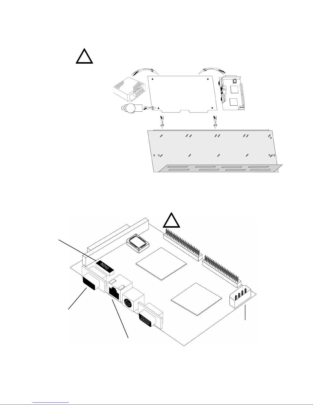
2.3 INSTALLING THE NFN WEB SERVER ASSEMBLY INTO A CAB-4 SERIES CABINET
This section describes the installation of the NFN Web Server Assembly into a CAB-3/CAB-4 series cabinet.
NOTE: Cabinet is ordered separately. For installation details,
!
1. The NFN Web Server, power supply
and PNET-1 surge suppressor are
installed onto the mounting plate. The
Web Server board uses four standoffs,
the power supply uses two screws, and
the PNET-1 uses one.
2. The mounting plate is installed
onto the CHS-4(L).
refer to the CAB-3/CAB-4 Series Installation Document, 15330.
3. The CHS-4(L) is
installed into the CAB-3 or
CAB-4 series cabinet.
Figure 2.3-1: NFN Web Server Installation Diagram
2.4 NFN WEB SERVER PC BOARD LAYOUT
The PC board layout (P/N 46173) is shown in Figure 2.4-1 below. Descriptions of pertinent connections are described
in subsequent sections.
NOTE: The replacement of the lithium battery
of the GENE-4310 CPU Board is to be
!
performed by a trained technician.
Modem connector (J5)
EIA-232 Port:
DB9-NUP connector - used
for operation as the network
connection to
NOTI•FIRE•NET™.
PC-PC connector - used for
configuration (cable supplied by customer).
RJ45 Ethernet Connector
(CN2) (to PNET-1)
Figure 2.4-1: PC Board Layout
HDD Power Connector
(P1)
NFN Web Server User’s Manual PN 51990:A2 12/02/03 15
www.PDF-Zoo.com
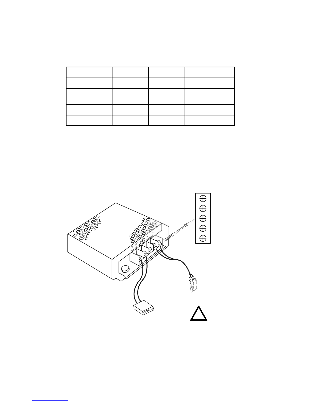
2.5 POWER SUPPLY CONNECTIONS
The power supply for the NFN Web Server is a 24VDC-to-5VDC unit (P/N 46175). The NFN Web Server requires
+24VDC @ 250 mA nominal and battery backup in accordance with local code requirements. It can be powered by
any power limited source that is UL listed for use with fire protective signaling units. For more details on powering
and connecting an NCM-W/F, refer to its Product Installation Document 51533.
TYPICAL MIN MAX
Input Voltage 24V 19V 29V
Input Current @24V
Output Voltage 5V 4.8V 5.2V
Output Current @5V 1.2A
360m A wi thout N CM
450 m A with NCM
Figure 2.5-1: 46175 Power Supply Specifications
NWS POWER SUPPLY CONNECTIONS WHEN USING THE NCM-W/F
When connecting the NWS to NOTI•FIRE•NET™ via the NCM-W/F, make cable connections according to Figure
2.5-2 below.
24V REF Input
+24VDC Input
Earth
P/N 46175
+5VDC Output
5V REF Output
Figure 2.5-2: NFN Web Server Power Connection
www.PDF-Zoo.com
Black
P/N 75581
Red
Red
To NWS PC Board
Power Connector
Black
NFN Web Server User’s Manual PN 51990:A2 12/02/0316
P/N 75583
To NCM NUP Port
NOTE: Not needed for direct
connection to an NFS-640 or
!
NFS-3030 panel.
 Loading...