

Page 1
May 9, 2005
DN-7006 • A1-340
ND-100 and ND-100R
Low-Flow Photoelectric Duct Smoke
Detectors for FireWarden-100
Section: Addressable
GENERAL
ND-100 and ND100R photoelectric duct smoke detectors are
used exclusively with the NOTIFIER FireWarden-100 (NFW-
100) addressable control panel. They provide low-flow technology that enables duct smoke detection throughout a broad
range of airflow environments in HVAC applications. The lowflow technology can detect smoke at air speed velocities of
100 feet per minute (0.5 m/sec) or greater, while continuing
the same reliable performance to 4,000 feet per minute (20.32
m/sec). The intelligent low-flow duct detectors sample air currents passing through a duct and gives dependable performance for shutdown of fans, blowers, and air conditioning
systems, preventing the spread of toxic smoke an fire gases
through the protected area.
ND-100 and ND-100R provide a remote alarm output for use
with auxiliary devices, such as the RA400 remote LED annunciator, as well as remote test capability with the RTS451 or
RTS451KEY Remote Test Stations. The ND-100R features a
Form-C relay.
APPLICATIONS
Duct smoke detectors have specific limitations, they are:
NOT
a substitute for open area smoke detectors.
•
NOT
a substitute for early warning detection.
•
NOT
a replacement for a building’s regular fire detection
•
system.
Please call NOTIFIER for a copy of System Sensor’s application guide,
tions
Proper Use of Smoke Detectors in Duct Applica-
, (A05-1004-00).
S635
MEA
320-02-E Vol. II
(ND-100R)
MARYLAND
State Fire Marshal
Permit # 2173
(ND-100R)
California
State Fire
Marshal
3240-0028:232
(ND-100R)
3240-0028:236
(ND-100)
6955pl.jpg
ND-100
FEATURES
• Air velocity rating from 100 to 4,000 feet per minute (0.5 to
20.32 m/sec).
• Patented telescopic sampling tube.
• Easily accessible code wheels for addressing detector.
• Outside mounting tabs.
• Mounts to round or rectangular ducts from 1’ to 12’ (0.3 to 3.7
meters) wide.
• Transparent cover for convenient visual inspection.
• Powered outputs for remote LED, and remote test and
sounder.
• Two Form-C auxiliary contacts (ND-100R).
• Patented cover-tamper trouble signal.
• ND-100R requires both com line power and one of the
following: 24 VAC/VDC or 120/220 VAC for operation.
INSTALLATION
Refer to installation manuals for control panel and duct
detector for detailed information or to install equipment.
Wiring: For signal wiring (the wiring between detectors or
from detectors to auxiliary devices), it is recommended that
single conductor wire be no smaller than 18 AWG (0.78 mm²).
This document is not intended to be used for installation purposes. We try to keep our
product information up-to-date and accurate. We cannot cover all specific applications or
anticipate all requirements. All specifications are subject to change without notice.
For more information, contact NOTIFIER. Phone: (203) 484-7161 FAX: (203) 484-7118
ND-100R
The duct smoke detector terminals accommodate wire sizes
up to 12 AWG (3.1 mm²). Flexible conduit is recommended for
the last foot (30.48 cm) of conduit; solid conduit connections
may be used if desired.
Smoke detectors and alarm system control panels have specifications for Signaling Line Circuit (SLC) wiring. Consult the
control panel specifications for wiring requirements before
wiring the detector loop. The ND-100 and ND-100R detectors
are designed for ease of wiring; their housing provides a terminal strip with clamping plates.
6955rpl.jpg
12 Clintonville Road, Northford, Connecticut 06472
DN-7006 • 05/09/05 — Page 1 of 4
Page 2

SPECIFICATIONS
ND-100
Operating voltage range: 15 to 30 VDC.
Standby current: 300 µA @ 24 VDC (one communication
every 5 seconds with LED blink enabled).
Operating temperature range: 32° to 131°F (0° to 55°C).
Operating humidity range: 10% to 93% relative humidity (non-
condensing).
Storage temperature range: –22°F to +158°F (–30°C to
+70°C).
Duct air velocity: 100 to 4,000 feet/min (0.5 to 20.32 m/s).
Shipping weight: 3.35 lbs. (1.5 kg).
Dimensions: 14.75" (37 cm) length x 5.50" (14 cm) width x
2.75" (7 cm) deep.
ND-100 accessory current loads
@ 24 VDC
PA400: refer to PA400 data sheet DN-2405.
RA400Z: 0 mA standby, 10 mA maximum in alarm.
RTS451 and RTS451KEY: 0 mA standby, 7.5 mA maximum
in alarm.
ND-100R
Operating voltage range: 20 to 30 VDC, 24 VAC/VDC, 120/
240 VAC
Standby current: 300 µA @ 24 VDC (one communication
every 5 seconds with LED blink enabled).
Operating temperature range: 32° to 131°F (0° to 55°C).
Operating humidity range: 10% to 93% relative humidity (non-
condensing).
Storage temperature range: –22°F to +158°F (–30°C to
+70°C).
Duct air velocity: 100 to 4,000 feet/min (0.5 to 20.32 m/s).
Shipping weight: 3.90 lbs. (1.8 kg).
Dimensions: 14.75" (37 cm) length x 5.50" (14 cm) width x
2.75" (7 cm) deep.
auxiliary power
(requires a separate auxiliary source
RA400Z RTS451
RTS451KEY
ND-100R current requirements (using no accessories)
Power supply voltage
20 – 30 VDC
24 VAC,
50/60 Hz
ND-100R contact ratings
Alarm auxiliary contacts* (DPDT):
• 10 A @ 30 VDC.
• 10 A @ 277 VAC (0.75 power factor).
• 240 VA @ 249 VAC (0.4 power factor).
• 1/8 HP @ 120 VAC.
• 1/4 HP @ 240 VAC.
Supervisory contact (SPST):
• 2.0 A @ 30 VDC (resistive).
*Minimum switching current for auxiliary contact must be 100 mA
DC minimum @ 5 VDC.
ND-100R accessory current loads
@ 24 VDC
PA400:
RA400Z: 0 mA standby, 12 mA maximum in alarm.
RTS451 and RTS451KEY: 0 mA standby, 10 mA maximum
in alarm.
See table below for ND-100R current requirements.
refer to PA400 data sheet DN-2405.
PRODUCT LINE INFORMATION
ND-100 Addressable low-flow duct detector housing
).
ND-100R Addressable low-flow duct detector housing
A5053FL Replacement photoelectric sensor board.
A5067 Replacement power board (without relay).
A5060 Replacement power board (with relay).
ST-1.5 Metal sampling tube, duct widths 1' to 2' (
ST-3 Metal sampling tube, duct widths 2' to 4'.
ST-5 Metal sampling tube, duct widths 4' to 8'.
ST-10 Metal sampling tube, duct widths 8' to 12'.
RA400Z Remote annunciator alarm LED.
RTS451 Remote test station. Mounts in single-gang
RTS451KEY Key-activated remote test station.
F36-09-11 Replacement filters.
M02-04-00 Replacement test magnet.
S08-39-01 Replacement photo insect screen.
P48-61-00 Replacement end cap for plastic sampling
P48-21-00 Replacement end cap for metal sampling
T80-71-00 Replacement sampling tube.
120 VAC,
50/60 Hz
with photoelectric smoke detector.
with photoelectric smoke detector with DPDT
relay.
see
table on page 3 for metric lengths)
.
box. Includes red alarm LED and magnet test
switch.
tube.
tube.
7006crnt.tbl
220/240 VAC,
50/60 Hz
Max. standby current 26 mA 65 mA RMS 44 mA RMS 25 mA RMS
Max. alarm current 87 mA 182 mA RMS 52 mA RMS 30 mA RMS
Alarm response time 3 to 10 sec. 3 to 10 sec. 3 to 10 sec. 3 to 10 sec.
Power-up time 2 sec. 2 sec. 2 sec. 2 sec.
Page 2 of 4 — DN-7006 • 05/09/05
Page 3
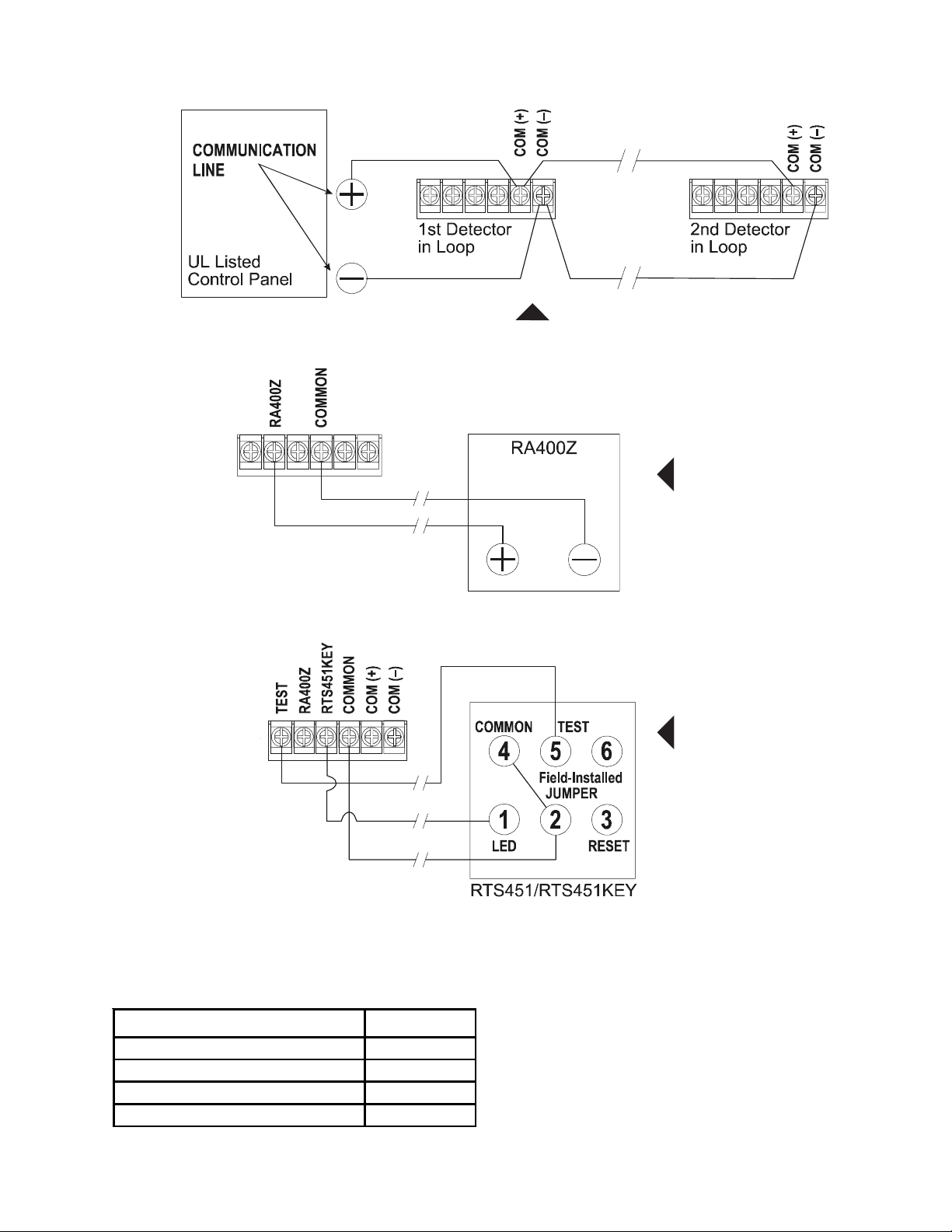
WIRING DIAGRAMS for ND-100
6821wir1.wmf
ND-100
Detector
Terminals
On to other
Detectors
on the Loop
ND-100 Duct Smoke Detector
using a UL-Listed control panel
ND-100 Duct
Smoke Detector
with optional
RA400Z
ND-100 Detector Terminals
INLET TUBE SELECTION
Outside Duct Width Inlet Tube*
Up to 2 feet (0.6096 m) ST-1.5
2 to 4 feet (0.6096 to 1.2192 m) ST-3
4 to 8 feet (1.2192 to 2.4384 m) ST-5
8 to 12 feet (2.4384 to 3.6576 m) ST-10
*NOTE: Inlet tube is required and must be purchased separately.
Order one inlet tube for each duct smoke detector ordered.
6821inlt.tbl
6821wir2.wmf
6821wir3.wmf
ND-100 Duct
Smoke Detector
with RTS451/
RTS451KEY
NOTE:
For RTS451,
is not used. RTS451 does not
have a Terminal 6.
For RTS451KEY,
and 6 are not used.
DN-7006 • 05/09/05 — Page 3 of 4
Terminal 3
Terminals 3
Page 4
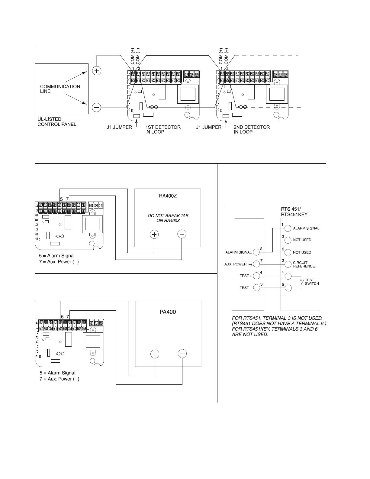
WIRING DIAGRAMS for ND-100R
ND-100R Duct Smoke Detector using a UL-Listed control panel:
NOTES: 1) Jumper J1 shunt must be installed for 2-W applications. J1 shunt must be removed
for power PCB supervision. Note that removal of shunt without adding external power will prevent
communications to the panel over the SLC. 2) External power of 24 V AC/DC or 120/220 VAC
must be connected in order to power all remote horn or strobe accessories.
ND-100R Duct Smoke Detector
with optional RA400Z:
ND-100R Duct Smoke
Detector with
RTS451/RTS451KEY:
7006wir1.wmf
ND-100R Duct Smoke Detector
with optional PA400:
7006wir2.wmf
7006wir3.wmf
7006wir4.wmf
Page 4 of 4 — DN-7006 • 05/09/05
 Loading...