

Page 1

www.PDF-Zoo.com
Network Control Station
NCS
Document 51095 3/08/02 Revision:
ECN 02-074
B1
Page 2

Fire Alarm System Limitations
While a fire alarm system may lower insurance rates, it is not a substitute for fire insurance!
An automatic fire alarm system—typically made up of
smoke dete ctors, heat detectors, m anual pull st a ti ons , aud ibl e
warning devices, and a fire alarm control with remote notification capability—can provide early warning of a developin g fire.
Such a system, however, does not assure protection against
property damage or loss of life resulting from a fire.
The Manufacturer recommends that smoke and/or heat detectors be located throughout a protected premise following the
recommendations of the current edition of the National Fire
Protection Association Standard 72 (NFPA 72), manufacturer's recommendations, State and local codes, and the recommendations contained in the Guide for Proper Use of
System Smoke Detectors, which is made available at no
charge to all installing dealers. A study by the Federal Emergency Management Agency (an agency of the United States
government) indicated that smoke detectors may not go off in
as many as 35% of all fires. While fire alarm systems are
designed to provide early warning against fire, they do not
guarantee warning or protection against fire. A fire alarm system may not provide timely or adequate warning, or simply
may not function, for a variety of reasons:
Smoke detectors may not sense fire where smoke cannot
reach the de tecto rs such as in chim neys, i n or behin d wal ls, on
roofs, or on the other side of closed doors. Smoke detectors
also may not sen se a fir e on an other level or fl oor o f a buildi ng.
A second-floor detector, for example, may not sense a firstfloor or basement fire.
Particles of combustion or “smoke” from a developing fire
may not reach the sensing chambers of smoke detectors
because:
• Barriers such as closed or partially closed doors, walls, or
chimneys may inhibit particle or smoke flow.
• Smoke part icles may become “col d , ” stratify, and not re ach
the ceiling or upper walls where detectors are located.
• Smoke particles may be blown away from detectors by air
outlets.
• Smoke particles may be drawn into air returns before
reaching the detector.
The amount of “smoke” present may be insufficient to alarm
smoke detectors. Smoke detectors are designed to alarm at
various levels of smoke density. If such density levels are not
created by a developing fire at the location of detectors, the
detectors will not go into alarm.
Smoke detectors, even when working properly, have sensing
limitations. Detectors that have photoelectronic sensing
chambers tend to detect smoldering fires better than flaming
fires, which have little visible smoke. Detectors that have ionizing-type sensing chambers tend to detect fast-flaming fires
better t han smol deri ng fire s. Be cause fir es dev elop in dif fer ent
ways and are often unpredictable in their growth, neither type
of detector is necessarily best and a given type of detector
may not provide adequate warning of a fire.
Smoke detectors cannot be expected to provide adequate
warning of fires caused by arson, children playing with
matches (es pecial ly in bed rooms), smoki ng in bed, and vi olent
explosions (caused by escaping gas, improper storage of
flammable materials, etc.).
Heat detecto r s do not sense particles of combustion and
alarm only when heat on th eir sensors inc reases at a pre determined rate or reaches a predetermined level. Rate-of-rise
heat dete ctor s may b e subj ect to re duced s ens itivit y ov er ti me.
For this reason, the rate-of-rise feature of each detector
should be tested at least once per year by a qualified fire protection specialist. Heat detectors are designed to protect
property, not life.
IMPORTANT! Smoke detectors must be installed in the
same room as the control panel and in rooms used by the system for the connection of alarm transmission wiring, communications, signaling, and/or power. If detectors are not so
located, a developing fire may damage the alarm system, crippling its ability to report a fire.
Audible warning devices such as bells may not alert people
if these devices are located on the other side of closed or
partl y o pen doors or are l oc at ed on a nother floor of a bui l ding.
Any warning device may fail to alert people with a disability or
those who have recently consumed drugs, alcohol or medication. Please note that:
• Strobes can, under certain circumstances, cause seizures
in people with conditions such as epilepsy.
• Studies have shown that certain people, even when they
hear a fi re alarm signa l, do not respo nd or comprehend the
meaning of the signal. It is the property owner's responsibility to conduct fire drills and other training exercise to
make people aware of fire alarm signals and instruct them
on the proper reaction to alarm signals.
• In rare instances, the sounding of a warning device can
cause temporary or permanent hearing loss.
A fire alarm system will not operate with out any elec trical
power . If A C power fails , the sys tem will operate from standby
batteri es only for a sp eci fied tim e a nd only if the ba tteries have
been properly maintained and replaced regularly.
Equipment used in the system may not be technically compatible with the control. It is essential to use only equipment
listed for service with your control panel.
Telephone lines needed to transmit alarm signals from a
premise to a central monitoring station may be out of service
or temporarily disabled. For added protection against telephone line failure, backup radio transmission systems are recommended.
The most common cause of fire alarm malfunction is inadequate maintenance. To keep the entire fire alarm system in
excellent working order, ongoing maintenance is required per
the manufacturer's recommendations, and UL and NFPA standard s. At a minimum, th e requirements of Chapter 7 of NFPA
72 shall be followed. Environments with large amounts of
dust, dirt or high air velocity require more frequent maintenance. A maintenance agreement should be arranged
through the local ma nuf act u rer ' s represent ati v e. Mai ntenance
should be scheduled monthly or as required by National and/
or local fire codes and should be performed by authorized professional fire alarm installers only. Adequate written records
of all inspections should be kept.
Precau-L-3-2002.fm
www.PDF-Zoo.com
Page 3

Installation Precautions
Adherence to the following will aid in problem-free installation with long-term reliability:
WARNING - Several different sources of power can be
connected to the fire alarm control panel. Disconnect all
sources of power before servicing. Control unit and associated equipment may be damaged by removing and/or inserting cards, modules, or interconnecting cables while the unit is
energized. Do not attempt to install, service, or operate this
unit until t his man ual i s read and understood.
CAUTION - System Rea cce pt ance Test afte r Sof t w are
Changes. To ensure proper system operation, this product
must be tested in accordance with NFPA 72 Chapter 7 after
any programming operation or change in site-specific software. Reacceptance testing is required after any change,
addition or deletion of system components, or after any modification, repair or adjustment to system hardware or wiring.
All components, circuits, system operations, or software functions know n t o be affected by a change must be 10 0% t este d.
In addition, to ensure that other operations are not inadvertently affected, at least 10% of initiating devices that are not
directly affected by the change, up to a maximum of 50
devices, must also be tested and proper system operation verified.
This syste m mee ts NFPA re quirement s f or operation at 0-49 °
C/32-120° F and at a relative humidity of 85% RH - 95% per
ULC - (non-condensing) at 30° C/86° F. However, the useful
life of the system's standby batteries and the electronic components may be adversely affected by extreme temperature
ranges and humidity. Therefore, it is recommended that this
system and all peripherals be installed in an environment with
a nomi nal room temperature of 15-2 7° C/60 -80° F.
Verify that wire sizes are adequate for all initiating and indicating d evi c e loops. Most devi ce s c annot tolerate more tha n a
10% I.R. drop from the specified device voltage.
Like all solid state electronic devices, this system may
operate erratically or can be damaged when su bjected to lightning-induced transients. Although no system is completely
immune from lightning transients and interferences, proper
grounding will reduce susceptibility. Overhead or outside
aerial wiring is not recommended, due to an increased susceptibility to nearby lightning strikes. Consult with the Te chnical Services Department if any problems are anticipated or
encountered.
Disconnect AC power and batteries prior to removing or
inserti ng circuit boards. Failure to do so can damage circ u it s .
Remove all elec tr o nic assemblies prior to any drilling, filing,
reaming, or punching of the enclosure. When possible, make
all cable entries from the sides or rear. Before making modifications, verify that they will not interfere with battery, tra n s former, and printed circuit board location.
Do not tighten screw terminals more than 9 in-lbs.
Over-tightening may damage threads, resulting in reduced terminal contact pressure and difficulty with screw terminal
removal.
Though designed to last many years, system components
can fail at any time. This system contains static-sensitive
component s . Alw ays ground yourself with a proper wrist str ap
before handling any circuits so that static charges are
removed from the body. Use static-suppressive packaging to
protect electronic assemblies removed from the unit.
Follow the i nstructions in the inst all at i on, operating, and programming manuals. These instructions must be followed to
avoid damage to the control panel and associated equipment.
F ACP operation and reliabi l ity depend upon proper ins tallation
by authorized personnel.
FCC Warning
WARNING: This equipment generates, uses, and can
radiate radio frequency energy and if not installed and
used in accordance with the instruction manual, may
cause interference to radio com munications. It has been
tested and found to comply with the limits for class A
computing device pursuant to Subpart B of Part 15 of
FCC Rules, which is designed to provide reasonable protection against such interference when operated in a
commercial environment. Operation of this equipm ent in
a residential area is likely to cause interference, in which
case the user will be required to correct the interference
at his own expense.
Acclimate Plus™, HARSH™, NOTI•FIRE•NET™, ONYX™, and VeriFire ™ are trademarks, and FlashScan® and VI EW® are regi stered trademarks of
NOTIFIER. NION™ and UniNet™ are trademarks of NIS. NIS™ and Not ifier Integrated Syst ems™ are trademar ks and NOTIFIER® is a registered
trademark of Fire•Lite Alarms, Inc. Echelon® is a registered trademark and LonWorks™ is a trademark of Echelon Corporat ion. ARCNET® is a regist ered
trademark of Datapoint Corporation. Microsoft® and Windows® are registered trademarks of the Microsoft Corporation. LEXAN® is a registered trademark
of GE Plastics, a subsidiary of General Electric Company.
Canadian Requirements
This digital apparatus does not exceed the Class A limits
for radiation noise emissions from digital apparatus set
out in the Radi o Int erfer ence Re gulat ions of t he Canad ian
Depar tment of Communications.
Le present appareil numerique n'emet pas de bruits radioelectriques depassant les limites applicables aux appareils numeriques de la classe A prescrites dans le
Reglement sur le brouillage radioelectrique edicte par le
ministere des Communications du Canada.
Precau-L-3-2002.fm
www.PDF-Zoo.com
Page 4

Table of Contents
Section 1 Installation ..............................................................................................................................................7
1.1: NCS Mounting and Connections................................................................................................................7
1.1.1: Related Documentation .....................................................................................................................7
1.1.2: NRT-NET Interface Card ..................................................................................................................8
1.1.3: NCS Equipment.................................................................................................................................8
1.1.4: Primary and Secondary Power ..........................................................................................................8
1.1.5: Connecting the NRT-P3.....................................................................................................................8
1.1.6: Monitor Installation...........................................................................................................................10
1.1.6. 1 I n sta ll i ng th e MO N - 1 9 BL K .... ... ......... ................. ......................... ................. .........................10
1.1.7: NCS UPS Supervision.......................................................................................................................12
1.1.7.1 NCS Computer/Monitor/Printer UPS Supervision .................................................................12
1.1.7.2 NCS Printer (only) UPS Supervision ......................................................................................13
1.1.8: Strain Relief.......................................................................................................................................14
1.2: Peripherals ...................................................................................................................................................15
1.2.1: Co n ne ct i ng a Li ne Pri n ter .......... .. ... .. ......................... ................. ........................ ..............................15
1.3: PC Configurations .......................................................................................................................................16
1.4: Software.......................................................................................................................................................16
1.4.1: Installing the NCS Software..............................................................................................................16
1.4.2: Installed Printers................................................................................................................................17
1.4.3: Read/Write CD ROM........................................................................................................................18
1.4.4: Windows 2000 Secure Desktop Configuration....................... .......... .......... ..................... .......... .......19
Section 2 Programming ..........................................................................................................................................20
2.1: Networking the NCS ...................................................................................................................................20
2.2: NCS Database..............................................................................................................................................20
2.2.1: History Database ...............................................................................................................................21
2.2.2: Graphics Database.............................................................................................................................21
2.3: Power-Up Initialization ...............................................................................................................................21
2.3.1: Data Refresh......................................................................................................................................21
2.3.1. 1 M an u a l D at a Refresh . ........................ ................. ........................ ................. ................ ............21
2.4: The Start - Up Window.............. ................... .......... ................... ................... .......... .......................................21
2.5: NCS Graphical User Interface.....................................................................................................................22
2.5.1: The Graphic Event Window..............................................................................................................22
2.5.1. 1 A u to m atic Screen Vector i n g ... ... ................. ................. ........................ ................. ..................22
2.5.1. 2 Ti t le Bar ........ .. .. ......................... ................. ........................ ................. ...................................23
2.5.1. 3 M en u Ba r .. ........................ ................. ........................ ................. ......................... ....................23
2.5.1.4 Graphic Floor Plan ..................................................................................................................24
2.5.1. 5 K ey M ap A rea ... ......................... ................. ........................ ................. ...................................24
2.5.1. 6 Ev e nt s W i nd o w .... .. ... ................. ................. ........................ ................. ...................................24
2.5.1.7 Acknowle dged Event Box .................................................. .....................................................25
2.5.1. 8 Screen Nav igatio n Too l s ....... .......... ................. ........................ ................. ..............................25
2.5.1.9 Date / Time Field ....................................................................................................................25
2.5.1.10 Logo Window ........................................................................................................................26
2.5.1. 11 To o l B ar .............................. ................. ........................ ................. ........................................26
2.5.1. 12 A la r m / Tr o ub l e / S u p er v is or y A la rm / Se cu r i ty A la rm Banner s ........... ..............................26
2.5.1. 13 C om m a nd A r ea ............ .. .. ......................... ................. ........................ ................. ..................26
2.5.1. 14 C urr ent Oper at o r Fi eld ..... ... .. ......................... ................. ........................ ................. .............27
2.6: Me nu O ptions for Pr o g ra mming ........ .. .. ......................... ................. ........................ ................ ...................27
2.6.1: Administration Menu ........................................................................................................................27
2.6.1. 1 Sy s t em Setup ........ .......... ................. ........................ ................. ........................ .......................27
2.6.1.2 Network Operations ...............................................................................................................33
2.6.1. 3 A rch ive Hist o ry D at ab ase ................... ................. ......................... ................. ................ .........35
2.6.2: Graphic Menu....................................................................................................................................35
2.6.2. 1 G rap h ic Setup .. .. ......................... ................. ........................ ........................ ............................35
2.6.3: Utilities Menu....................................................................................................................................35
2.6.4: The Help Menu..................................................................................................................................36
www.PDF-Zoo.com
4
Document #51095 Rev.B1 3/7/02
Page 5

Table of Contents
Sectio n 3 Op e r a ti on ...................... ........................ ................. ........................ ................. ........................................38
3.1: Normal Ope ration.... ... .. ................. ........................ ................. ......................... .............. ..............................38
3.2: Troubles.......................................................................................................................................................38
3.3: Ala rm s .. ......... ......................... ................. ........................ ................. ...................... .....................................39
3.4: Supervisory, Security, and Pre-Alarm .........................................................................................................41
3.5: Menu Options for Operating the NCS.........................................................................................................41
3.5.1: Fi le Menu . ... .. ... ........................ ................. ........................ ................. ...............................................41
3.5.1.1 Ex it ......... .. .. ......................... ................. ........................ ................. ..........................................41
3.5.2: Op er ator Men u .......... ... .. ................. ................. ........................ ................. ................. .......................41
3.5.2.1 Lo g in ... ........................ ................. ......................... ................. ........................ .........................41
3.5.2.2 Lo g out . ................. ................. ........................ ................. ......................... ................................42
3.5.2.3 Ch a ng e Pa ss wo r d ...... .. ......................... ................. ........................ ................. .........................42
3.5.3: Th e Ac ti o n M en u .................. ................. ......................... ................. ........................ .........................42
3.5.4: The View Menu.................................................................................................................................43
3.5.4.1 Ev en t Co u nt ers .......... .. ... ................. ........................ ................. ......................... ......................43
3.5.4.2 Th e D et ai le d Eve n ts Window .. ......... ................. ......................... ................. ...................... .....44
3.5.4.3 Cu r ren t Event W i ndo w ............ .. ................. ................. ........................ ......................... ..........45
3.5.4.4 Disabl ed Device Window ............. .......... .................. ..................... .......... .......... .......... ...........45
3.5.4.5 H ist o r y Man ager .................................. ........................ ................. ........................ ..................45
3.5.5: Scr e en N av i ga tion ..... ... .. ... ........................ ................. ........................ ................. ........ ......................46
3.5.6: Troub l e w it h NC S an d IN A E q u ipm e n t......... .. ................. ................. ......................... ................ ......46
3.6: Read Stat us/Prog r am ......... ................. ........................ ................. ........................ ........................................47
Sectio n 4 T h e Hi s t or y Man a g e r ..... ... ........................ ................. ........................ ................. ...................................52
4.1: NCS Integrated Operation ...........................................................................................................................52
4.1.1: History Backup..................................................................................................................................56
4.1.1.1 U plo ad /Downl o ad (UPDL) ...... .. .......... ................. ........................ ................. .........................57
Sectio n 5 T h e Gra p hic Set up Pro g ra m ...................... ................. ......................... ................. ................................60
5.0.1: NCS Integ r at ed O pe r at io n.................. ................. ........................ ................. .....................................60
5.1: Program Layout...........................................................................................................................................60
5.1.1: Fl oo r Plan Tree View ... .. ... ................. ........................ ................. ........................ ..............................61
5.1.2: Gr o up Tree View.. ......................... ................. ........................ ................. ..........................................61
5.1.3: Fl oo r Plan Device View........ .......... ........................ ......................... ................. .............. ..................61
5.1.4: Information Windows .......................................................................................................................61
5.1.5: Tool Bar.... ... ......... ................. ......................... ................. ........................ ..........................................62
5.2: Grap h ic Fl o o r Pl an s........... ........................ ................. ........................ ................. ........................................63
5.2.1: Ad d in g Fl o o r Pl an s to th e N CS............ ................. ........................ ................. ...................................63
5.2.2: Selecting Floor Plans.........................................................................................................................64
5.2.3: Deleting Flo o r Pla ns........................... ................. ........................ ................. ............... ......................64
5.2.4: Set t in g Ke y m a p Li n ks.. .. ................. ........................ ................. ......................... ................................65
5.2.5: Scr e en Title ... ... ......... ......................... ................. ........................ ................. .....................................65
5.2.6: Gu id ance Text .. .. ................. ........................ ................. ......................... ................. ...........................65
5.3: Keym a p Ar e a ................ ........................ ................. ......................... ................. ............................................66
5.4: Men u Bar O p ti o ns .......... ................. ......................... ................. ........................ ..........................................66
5.4.1: Fi le............... ........................ ................. ........................ ................. ....................................................66
5.4.2: Scr e en s ......................... ................. ........................ ................. ........................ ...................................66
5.4.3: Dev ices.................... ........................ ................. ........................ ................. ........................................66
5.4.4: View ............ .. ... ......... ................. ......................... ................. ........................ ....... ..............................68
5.4.5: Set u p.... .......... ................. ........................ ................. ......................... ................. ................................68
5.4.6: Help........ .. ... ........................ ................. ........................ ................. ....................................................69
5.5: Device Icons ............................. ........................ ................. ......................... ............... ..................................69
5.5.1: Dev ices.................... ........................ ................. ........................ ................. ........................................69
5.5.2: Detector s ....... ... ......... ................. ......................... ................. ........................ ......... ............................70
5.5.3: M o d ules.......................... ........................ ................. ......................... ................. ................................70
5.5.4: Zo ne s ... ... .......... ........................ ................. ........................ ................. ...............................................70
www.PDF-Zoo.com
Document 51095 Rev. B1 3/7/02 5
Page 6

Table of Contents
5.5.5: Linked Files.......................................................................................................................................70
5.5.6: Information Labels ............................................................................................................................70
5.5.7: Navigational Buttons.........................................................................................................................71
5.5.8: Delete Operations..............................................................................................................................72
5.5.9: Searching for Specific Items .............................................................................................................72
5.5.10: Rules for Setting Up Device Graphics ............................................................................................72
5.6: Groups .........................................................................................................................................................73
5.6.1: Level 1 Groups..................................................................................................................................73
5.6.2: Level 2 Groups.................................................................................................................................73
5.6.3: Group Setup Restrictions .............................................. .............................................. ......................73
5.6.4: Group Navigation.......................... ...................................................... ..............................................73
5.7: Setup Templates...........................................................................................................................................74
5.7.1: Template Groups ...............................................................................................................................74
5.7.2: Hot Templates....................................................................................................................................74
5.8: Custom Bitmap............................................................................................................................................74
5.9: Template Files .............................................................................................................................................75
5.10: NCS Required Files...................................................................................................................................75
Appendix A: Windows 2000 Security Disable Procedure ..................................................................................76
Appendix B: M iscellaneous So f twa re Insta l la t io n . ........................ ................. ........................ ............................77
Appendix C: Message Tables ................................................................................................................................78
www.PDF-Zoo.com
6
Document #51095 Rev.B1 3/7/02
Page 7

NCS Mounting and Connections Installation
Section 1 Installation
1.1 NCS Mounting and Connections
The Network Control Station (NCS) contains a recognized tabletop computer with VGA graphics
for displaying all network events. The NCS is used with the Notifier Noti•Fire•Net system. The
different NCS models all come with the NRT-P3, a high-performance desktop computer.
1.1.1 Related Documentation
To obtain a complete understandin g of the NCS features an d related pr oducts or to become familiar
with functions in general, make use of the documentation noted in Table 1.1. The Notifier
document (DOC-NOT) chart provides the current document revision.
Title Number Title Number
AM2020/AFP1010
Fire Alarm Control Panel
Liquid Crys tal Display (LCD-80) 15037 Annunciator Control System 15842
Network Cont rol Station (NCS) 51095 Lamp Driver Modules (LDM) 15885
Intelligent Network Annunciator (INA) 15092 Voice Alarm Multiplex 15889
Universa l Zone Coder Installation (UZC-256) 15216 The XP Series Transponder Syste m 15888
Product Installation Document (CCM-1) 15328 Network Adaptor Module (NAM-232) 50038
Product Installation Document
(MPS-TR)
AM2020/AFP 1010 Oper ator Inst ru ct ions 15337 FCPS-24 / F C PS-24E Fie l d C h arger/Pow er Sup p l y
Notifier Device Compatibili ty Document 15378 Video Graphics Annunciator System (VGAS)
Analog Fire Panel (AFP-200) 15511 Media Inter face Board (MIB) 50255
Analog F i r e P anel I n s talla tion M anual ( A F P-400 ) 50253 Repeater (RP T) 50256
Analog Fire Panel Programming Manual (AFP-400) 50259
Analog F i r e P a n el Operatin g Ma n u a l (AFP - 4 0 0 ) 50260 Smoke Control Manual 15712
Canadian Requirements for the AM2020/AFP1010 15631 SLC Manual 51253
Network Int erface Board (NIB-96) 15666 MMX-2 Installation In structions M500-03-00
RM-1 Series Remote Microphones 51138 XP5 Series Transponders 50786
50119/
15088
15331 The UDACT Universal Digital Alarm
CHG-120 50641
Communicator/Transmitter
Installation, Operation and Application Manual
Installation Manual
Noti•Fire•Net Manual
50050
50059
50251
50257
NBG-12LX Pull Station 51093 ACT-2 Audio Coupli ng Transformer 51118
NCS Manual PN 51095:B 1 3/08/02 7
www.PDF-Zoo.com
Ta ble 1.1 Related Documentation
Page 8

Installation NCS Mounting and Connections
.
1.1.2 NRT-NET Interface Card
The NCS com municat es with Noti•Fire•N et throug h th e Network interface card (NRT -NET) and
the Medi a Interf ace Board (MIB). The NRT-NET interface card plugs dir ectly into a computer
expansion slot located on the NCS computer. The MIB, which supports the physical c onnection to
the network, plugs onto the NR T-NET card to complete the network interface. The NRT-NET
interface card provides the following features:
• A ll o w s th e N C S co m p u te r to com munic at e on N oti•Fire• N et
• Accepts the following choic es of Media Interface Boards:
- twisted-pair (MIB-W)
- Fiber optic (MIB-F)
JP3, IRQ7
The jumper
provided must
cover these p ins i f
the NCS is not
NRT upgrade.
Note: If the NCS
is an NRT
upgrade, t he pins
at JP3, IRQ3 must
be covered.
an
JP6 - Present on the NRT-NET card of an
NCS or later model NRT. Do not remove
the jumper at JP6, which is set at 300H.
Figure 1.1 NRT-Net Card
Monitors normally closed contacts of
uninterruptible power supply (UPS). If
unused, cover pins using supplied jumper.
LED illuminates to indicate
that NFN is receiving data.
LED illuminates to indicate
that NFN is transmitting data
LED illuminates to indicate
activity on Channel A.
LED illuminates to indicate
activity on Channel B.
1.1.3 NCS Equipment
The Network Control Station is a kit comprised of:
• a co m p uter
• A MON-19BLK monitor (UL 864 Listed 19 inch monitor)
Refer to Table 1.2 for m odel numbers and components.
Note: The monitor and mouse, as well as the printer if one is used, must be installed in the same room as the NCS in order
to comply with UL listing requirements.
A PRN-5 pri nte r ca n be or de red sep ar ate ly.
The NCS computer is referred to in this manual as the NRT-P3. Table 1.2 lists the NCS model numbers
that include computers referenced as NRT -P3.
8 NCS Manual PN 51095:B1 3/08/02
www.PDF-Zoo.com
Model # Components
NCS-M19F NCS com pu ter, mouse, 19" monito r , fiber optic data lin k
NCS-M19W NCS compu ter, mouse 19" monitor, wire dat a lin k
Table 1.2 NCS Equipment Options
1.1.4 Primary and Secondary Power
The NCS require s connection to a s eparate dedicated primary AC fire alarm circuit, which must be
labeled "FIRE ALARM." This AC ci rcuit must connect to the line side of the main power feed of
the protected premis es. No other equipment can be powered from the fire alarm circuit. The
primary AC circuit wire run must run continuousl y, without disconnect devices, from the power
source to the NCS. Overcurrent protection for this circuit must comply with Article 760 of the
National Elect r ical Code as well as local code s . Where an NCS is require d
, the use of an UL-864
approved supervised UPS is also required. When using a UPS, NCS input voltage must be 115
VAC. The use of 230 VAC is not permitted when employing a UPS.
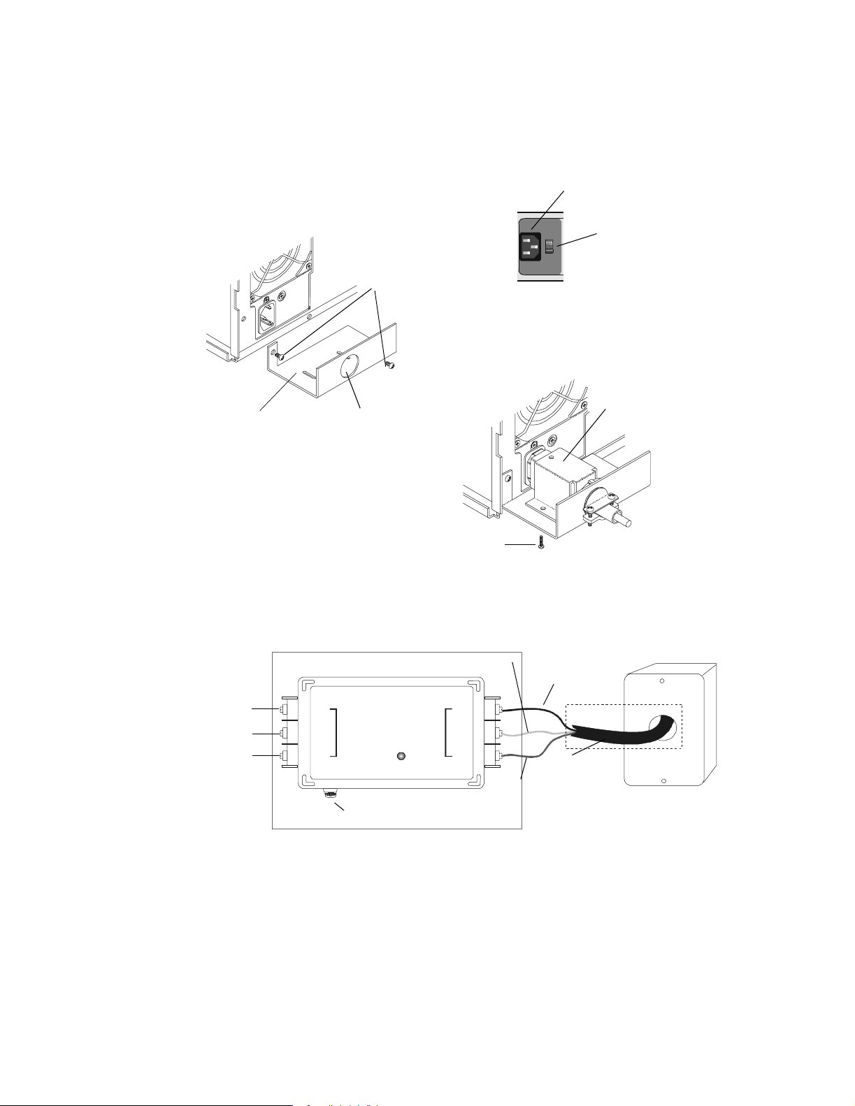
1.1.5 Connecting the NRT-P3
The following steps must be co mpl eted when connecting the NRT-P3 (refer to
Figure 1.2 and Figure 1.3).
Page 9

NCS Mounting and Connections Installation
B
1. Cut off the plug end of the computer power cord.
2. Pl ug th e s o ck e t en d of th e po w e r cor d in t o th e computer.
3. Remove the screws from around the power s upply of the NR T-P3.
4. Attach the PCLB-6 enclosure without the cover to the back of the NRT-P 3 us ing these screws.
5. Install a 3/4-inc h (19.05 mm) conduit and fitting in the knock-out hol e of the Power Cord
Locking Bracket cover (refer to Figure 1.3).
Caution: Size the 3/4-inch (19.05 mm) conduit so the line cord can reach a junction box at the
!
other end of the conduit.
6. Thread the power cord through the cover and conduit.
7. Attach the PCLB-6 cover to the PCLB-6 using the mounti ng s crews supplied. Ensure t hat the
PCLB-6 cover holds the power cord soc ket firmly in place.
8. Connect the power cord to the HSP-121B power line prote ctor as shown in
Figure 1.4.
Note: The HSP-121B power line protector must reside in a junction box.
9. Connect 1 15 VAC, 50/60 Hz primary power or 230 VAC, 50/60 Hz primary power to the HSP-
121B as shown in Figure 1.4. Primary power connected to the HSP-121B (115 VAC or 230
VAC) depends upon the posit ion of the voltage sele ction switch shown in Figure 1.2 and
Figure 1.3. All wiring must remain in conduit.
WARNING: Improper voltage selection can damage the NCS and void the warranty on the
!
back cover of this manual.
10. Turn power sw itch on for the circuit.
11. Replace the cover on the PCLB-6 enclosure and secure with two screws.
12. Connect the monit or to the display adapter video connecto r on the back of the computer (re fer
to Figure 1.2). Connec t the other end of the video cable to the monitor. The video cable is
provided with screws for se cure attachment.
13. Align the keyboard cable plug to mate with the notch in the computer's jack and insert cable.
14. Connect the mouse to the mouse port at the back of the NRT-P3.
15. Refer to Figure 1.5 for monit or power application.
Not Used
Microphone Connector
EIA-232
Speaker C onnector
Power
Cord
Socket
Remove these
screws and reuse
for mounting the
PCLB-6 plate
Voltage
Selection
Switch
Power Switch
(disabled at
factory)
EIA-232
COM Ports
3 and 4
Not Used
Mouse/Keyboard Port
Figure 1.2 NRT-P3 C onnections
Not Used
Not used
COM Por t s
1 and 2
Software Key
connection
Monitor
connection
Noti•Fire•Net
Connections
Not Used
NRT-NETPC
LEDs
UPS
Supervision
Cable
Connection
NRT-NETPCB Ca rd
NCSonyx3bk.cdr
NCS Manual PN 51095:B 1 3/08/02 9
www.PDF-Zoo.com
Page 10
Installation NCS Mounting and Connections
• The NRT-P3 requires 1 15 VAC, 50/60Hz primary power or 230 VAC, 50/60 Hz pri m ary power depen ding upon the
position of the voltage selection switch shown in Figure 1 .2 and Figure 1.3.
• Where an NCS is required, the use of a supervised Uninterruptable Power Supply (UPS) is also required (see Figure
1.6)
• The NCS is not suitable for use as a receiving unit.
• The front power switch for the NRT-P3 has been permanently fixed in the ON position.
Power Cord
Voltage selection
Switch
To 115 VAC, 50/60
Hz Primary Power or
230 VAC, 50 /60 Hz
Primary Power
PCLB-6
(without cover)
Black
White
Green
Mounting Screws
PCLB5Bb.cdr
Knockout
Mounting Screw
Figure 1.3 Attaching the PCLB-6 to the NRT-P3
Junction Box
AC
NEUT
GND
HSP-121B
L
I
N
E
Light ON - Normal
Light OFF - Requires Service
15 AMPS
MAX
E
Q
U
NEUT
I
P
GND
Neutral - White
AC
Ground - Green
nrtpwcrd.cdr
AC - Black
Conduit
Power Cord
PCLB-6 Cover
PCLB-6
PCLB5Ba.cdr
hsp-121b.c dr
1.1.6.1 Installing the MON-19BLK
10 NCS Manual PN 51095:B1 3/08/02
www.PDF-Zoo.com
Fuse
Figure 1.4 Conn ecting the Power Cord and Primary AC Power
to the Power Line Protector
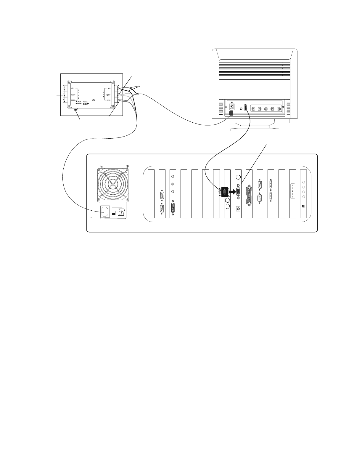
1.1.6 Monitor Installation
The following ste ps must be compl et ed when conne cting the MON-19B LK to th e Jun ction B ox and
NRT-P3 (refer to Figure 1.5).
1. Connect the AC Power Cord on the MON-19BLK to the HSP-121B Junction Box.
2. Connect the DB-15 video cable to the video card slot on the NRT-P3.
Page 11
NCS Mounting and Connections Installation
B
W
G
MON-19BLK
lack
hite
reen
Junction Box
HSP-121B
Fuse
Neutral - White
Ground - Green
AC - Black
Power Cord
DB-15 Cable
NCS Computer
Monitor
Connection
NCSmoninstonyxnrtnet.cdr
Figure 1.5 Installation of MON-19BLK
NCS Manual PN 51095:B 1 3/08/02 11
www.PDF-Zoo.com
Page 12

Installation NCS Mounting and Connections
908172635
4
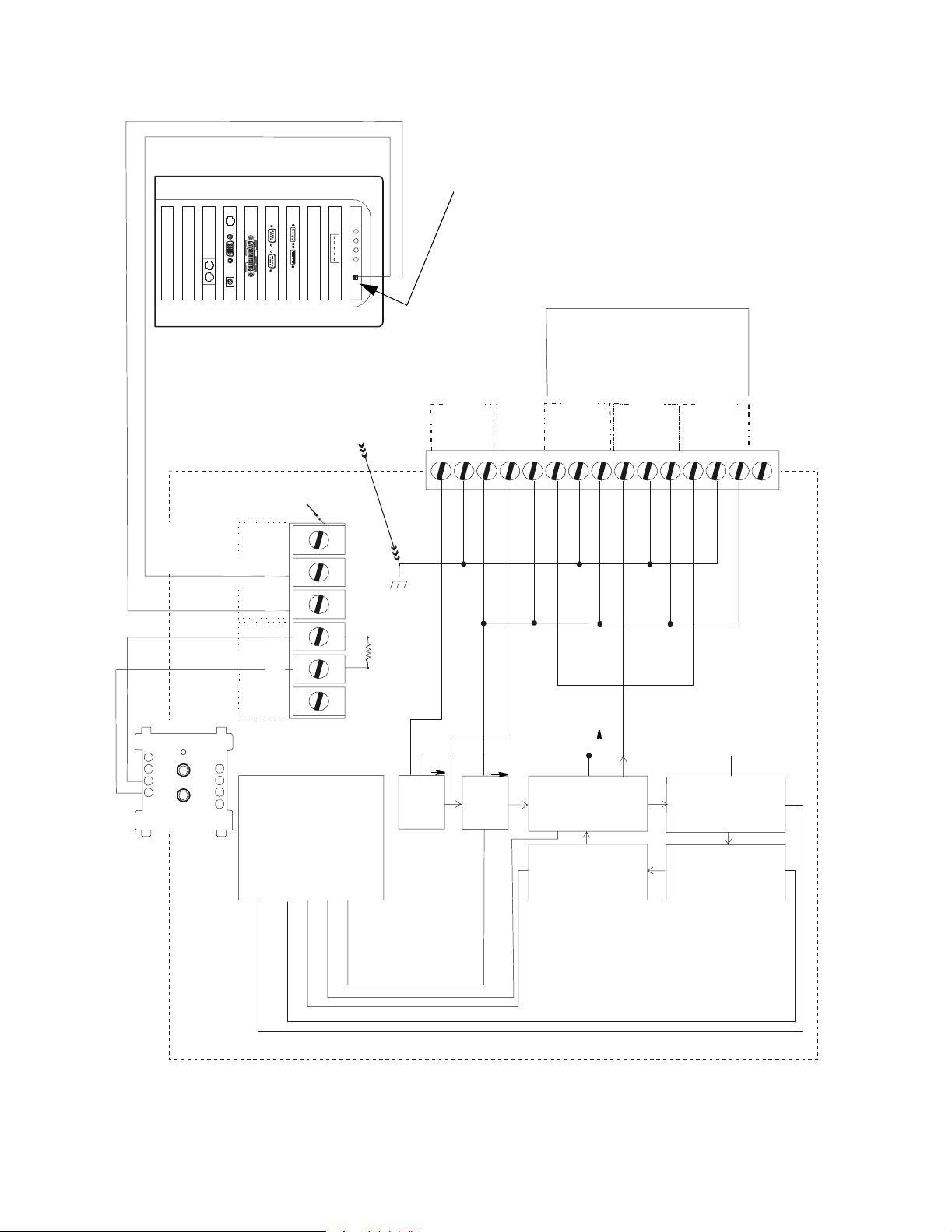
1.1.7 NCS UPS Supervision
1.1.7.1 NCS Computer/Monitor/Printer UPS Supervision
Where a Network Reporting Terminal (NCS) is not ancilla r y, the use of a supervised 1 15 VAC
Uninterruptable Power Supply (UPS) is required. Refer to Figure 1.6 and Figure 1.7 for wiring
information. A networked AM2020/AFP1010 or INA with an MPS-24A Power Supply must be
located within three feet (.9144 m) of the UPS and wiring must be in con duit.
Negative Bar
AC Input
To AC Power of
NCS, Printer, or CRT
Note: The Inverter is equipped
with automatic transfer. Refer to
the schematic in the instruction
manual for internal wiring.
DC
Output
AC
Load
115 VAC
DC/AC Inverter
Inverter
Failure
47k ELR
(optional)
Note: Wiring should be in the same
cabinet or use less than 3 feet of conduit.
Positive Bar
AC Line
115 VAC
COMM
NC
NC
Utility Failure
DC
Output
Use cable P/N 71033 (suppl ied
with the NCS) from
NRTNETPCB to UPS. Cut and
strip wires as needed. Make all
connectio ns in cond ui t.
NRT-P3 Computer
12 NCS Manual PN 51095:B1 3/08/02
www.PDF-Zoo.com
Charger 1
Sense (+)
Remote
Equalize
Charger 2
Load
Sharing
Remote
Sense (-)
Remote
Rectifier
Failure
Low
Current
Remote
Equalize
Remote
Sense (+)
Load
Sharing
Remote
Sense (-)
Rectifier
Failure
+
Low
Current
NCSsupsfsonyxnrtnet.cdr
-
FMM-1
Figure 1.6 NCS Computer UPS Supervision
Page 13
NCS Mounting and Connections Installation
456789101112131415123
1.1.7.2 NCS Printer (only) UPS Supervision
NRT-NETPCB
UPS Supervision Port
Total Output Load
5A AC Maximum
Battery Backed Up
120V AC
Output
Of UPS
120V AC
Output
Of UPS
120V AC
Output
Of UPS
GND
SPARE
N
H
Relay Contacts A re Rated
500 mA, 28V DC
500 mA, 28V AC
Note: Cut and Strip
Wires on Cable
Assembly P /N 71033
(provided wi th NCS),
and connect as shown.
Battery
AC
Input
Fail
Fail
}
(NO)
(NC)
(NO)
Chassis Ground
Resistive Load
1
2(C)
3
4
5(C)
47K
ELR
Input Power
120V AC, 60 Hz
8A AC Maxim um
H
GND
No Connection
No Connection
N
H
GND
H
N
N
H
GND
N
90
81
+
72
6
_
54
Software Type
ID "MTRB"
FMM-1
6
(NC)
3
UPS
System Control
EMI
Line
Filter
Static
Switch
Transformer
Charger
Board
Inverter
Battery
Instrumentation and Control System, Inc.
UPS, Mod e l Number 9300057
upsprn1fsconyxnrtnet.cdr
Figure 1.7 NCS Printer UPS Supervision
NCS Manual PN 51095:B 1 3/08/02 13
www.PDF-Zoo.com
Page 14

Installation NCS Mounting and Connections
1.1.8 Strain Relief
Strain relief for wiring attached to the NCS wire terminals on the MIB-W is provid ed by a
protective cover (P/N 08275). The protective cover is supplied with the MIB-W.
The following steps mus t be co mpl eted to connect the protective cover with strain relief:
3. Feed wires to be connected to the terminal block through the back or side access hole of the
protective cover. The hinged covers of the unused access hole can be closed.
4. Attach the wires to the pluggable terminal block.
5. Snap the strain relief assembly over the pluggable terminal block. Use tie wra p to secure the
wires to the protective cover (refer to Figure 1.8).
Tie Wrap Around Wire and
Hinged Cover
Wiring Access Holes and
Hinged Covers
Strain Relief Assembly
(snaps over pluggable ter m inal block)
Cable Restraint
(add after assembly)
Protecti ve Cover
(P/N 08275)
Figure 1.8 Strain Relief Assembly
strainre.cdr
NRTNETPCB
NCSonyx3back.cdr
14 NCS Manual PN 51095:B1 3/08/02
www.PDF-Zoo.com
Page 15

Peripherals Installation
1.2 Peripherals
1.2.1 Connecting a Line Printer
A printer can be connected to the NCS to print fire alarm and trouble signals (refer to F igure 1.9
and Table 1.3).
DB 9 connector
DB 25 connector f r om PR N
or another listed EDP printer
Figure 1. 9 Serial Port Connections for a Printer Connected to NRT-P3
Cable
To connect a PRN-4 or PRN-5 printer to the NCS, a cable with the connections shown in Table 1.3
must be prepared.
NCS
DB9
22
33
57
4 and 6
jumpered
together
820
Printer
DB25
Table 1.3 Prin ter Conn ec t ion s
• Only one NCS (including keyboard, mouse, monitor, or any one of these) can be present on the network for other than
National Fir e Pr otection Association (NFPA) 1996-72 Local Ser vice.
• Where an NCS is required, the use of a supervised 115 VAC UPS is also required (see Figure 1.6 or Figure 1.7).
• Locate the printe r in the sam e room as th e NCS .
• This printer connection is not for use with V eriFire. Refer to the VeriFire documentation for further information.
NCSdbcxonyxnrtnet.cdr
NCS Manual PN 51095:B 1 3/08/02 15
www.PDF-Zoo.com
Page 16

Installation PC Configurations
1.3 PC Configurations
To run the NCS program your system must be setup for the following config urations:
1024 x 768 resolution, large fonts , and 65k colors. Refer to Figure 1.10. To s et these
configurations, select the S tart menu and Settings/Control Panel, double-click Display and select
the Settings tab.
1.4 Software
cspcconfig.jpg
Figu r e 1.10 PC Configuration s
For Windows 2000, the font size is located in a submenu of the Settings screen. Click the
"Advanced" button that appears at the bottom right of the Settings screen. On the next screen,
choose "Large" for font size.
Additionally, for Windows 2000, the Active Desktop setting must be off.
1.4.1 Installing the NCS Software
Make sure to read the entire set of instructions prior to beginning the NCS software install ation.
The NCS software requires Windows 2000 Professional Edition with Service Pack 1or higher, or
Windows NT® with Service Pack 5. The following steps must be completed to install NCS
software in Windows NT
Note: If the NCS is the Master Time Keeper on the network, installing this software will cancel the setting and a Master
Time Keeper will not exist on the network. Enter the date/time in the NCS Local Programming Dialog Box for the NCS to
become the Master Time Keeper again.
Windows NT® is a registered trademark of Microsof t Corporati on.
1. Insert the CD-ROM i nto the a ppropri ate d rive. The Se tup p rogra m will launc h autom atic ally i f
Autorun is enabled. Otherwise, continue with s teps 2 through 10 that follow.
2. Click on the Start button, sele ct Run...
3. At the Command Line prompt, type X:\NCS, where X is your CD drive letter. Steps 2 and 3
will only be necessary for PCs that do not have the Autorun feature enabled.
®
Workstation 4.0 or in Wnidows 2000.
16 NCS Manual PN 51095:B1 3/08/02
www.PDF-Zoo.com
Page 17

Software Installation
4. An InstallShield Self-Extracting.exe dialog box wi ll ap pear, select YES to conti nue inst alli ng
the NCS. InstallShield will start extracting the necessary files for installing the NCS.
5. A Welcome dialog box will appear. Select NEXT t o continue installing or CANCEL to return
to the de sk top.
6. A User Information dialog box will appear next. Type your name and company at the
designated prom pts . Select NEXT to continue or CANCEL to return to the desktop. The
location of the installation directory will be displayed if it exists, and the user will be asked if
he/she would li ke to make a backup.
7. Next a Select Pro gr a m Fo l der dialog box appears. The NCS must be installe d in the
directory provided.
8. A Setup Type dialog box will now appear. Choose Typical, Compact or Custom setup by
clicking in the appropriate circle. Select NEXT to continue installing, BACK to view the
previous screen or CANCEL to return to the desktop.
• Typical Install - Installs th e most common opt ions, recommended for most user s.
• Compact Install - Not available at th is time.
• Custom Ins ta ll - Th e us e r ch oos es t he i ns talle d o p tio ns , re co mmend ed f o r ad van ced u sers . Th e
Select Program Fol der dialog box displays for this purpose.
9. Next a Start Copying Files dialog box appears showing the type of setup, target folder and
user informati on t hat was pro vided. Sel ect NEXT t o begin c opying fi les, BACK to c hange a ny
settings or CANCEL to ret urn to the desktop.
10. The NCS will now install the NCS. When se tup is complete, a Setup Complete dialog box
appears informi ng you that the computer will be rebooted. Press OK to perform the reboot.
Caution: The NCS Comm unication s D river may have to be changed. If the N CS is installed on a
PC that did not contain th e N RT (Network Report ing Terminal), it will use IRQ 5 or IRQ7.
!
The NCS Inst al lat ion Pro gram se ts th e IRQ to I RQ5. On O ny x comp ut ers, or c ompu ter s tha t a lrea dy
use IRQ5, this must be changed to IRQ7. Please be sure the jumper selection on the NRT-NETPCB
card is set to IRQ7. In addition, please complete the following steps to configure the software:
1. Open a text editor , such as Notepad.
2. Open file ptp20020.ini. This file is locat ed in the \notifier\ncs directory.
3. L ook for IRQLevel = REG _D WORD 0x05. Change the 0x 05 to 0x07.
4. Save the fi le , cl os e N o te pa d.
5. Open the DOS command prompt, and change to the \notifier\ncs directory.
6. Type "regini ptp20020.ini"
7. This completes the software configuration. Reboot the computer for the change to take effect.
To verify that the NCS Communicat ions Driver is configured correctly, follow these steps in
Windows 2000.
1. From the Start Menu, open Control Panel, then double click on Administrative Tools.
2. Double click on Computer Management.
3. Navigate to Sy stem Inform ation, then select Hardware Resources, followe d by IRQ s.
4. Verify that IRQ7 is displayed, and the Device indicates ptp20020.
1.4.2 Installed Printers
Two printers may be installed to the NCS: an NCS Graphics Printe r (optional, any Microsoft Windows compatible printe r that is UL ITE listed and installed in the same room as the N CS) which is
used to print out graphics, reports, etc. and an NCS Line Printer (the PRN) which is used only to
print out text.
NCS Manual PN 51095:B 1 3/08/02 17
www.PDF-Zoo.com
Note: The NCS Graphic Printer must be a laser printer.
Installing The Graphics Printer
1. Exit the NCS application.
Page 18

Installation Software
RESET
POWER
n
2. From the Sta r t Menu, select Settings, and then Printe r s.
3. D o ub le-click on th e "Add Printer" ic on.
®
4. The Windows NT
Installation Wizard will start to add the new printer.
5. Select the "My Computer" button, cli ck next. The following ite ms should be selected on the
next screens.
• The printer must be connected to LPT1.
• Select the printer that is to be hooked up to the system.
• Select Not Shared.
• Name the printer “NCS Graphic Printer”.
Caution: This entry is case sensitive: the printer name must be entered exactly as shown.
!
6. In the printer dialog box, highlight the printer jus t installed, right click and select properties.
Installing The Line Printer
1. Exit the NCS application.
2. From the Sta r t Menu, select Settings, and then Printe r s.
3. D o ub le-click on th e "Add Printer" ic on.
®
4. The Windows NT
Installation Wizard will start to add the new printer.
5. Select the "My Computer" button, cli ck next. The following ite ms should be selected on the
next screens.
• The printer should be c onnected to LPT1 or a serial port.
• Select the printer that is to be hooked up to the system.
• Select Not Shared.
• Name the printer “NCS Line Printer”.
6. In the printer dialog box, highlight the printer jus t installed, right click and select properties.
Note: If the NCS Line Printer is connected to a serial port, the port settings must match the printer settings.
1.4.3 Read/Write CD ROM
File Directories on the NCS contain
infor m a tion specific to nor m a l NCS
operation. User -defined directories for
capturing history files (.HIS) may also e xist
on the NCS. The files in these directories
may be backed up to the Read/Write CD
ROM. The Read/ Write CD drive is locat ed
as shown in Figure 1.11. Follow the steps
below to copy NCS informa tion onto a CD.
1. Exit NCS
Caution: Exiting the NCS application disconne cts the NCS from Noti•Fire•Net which leaves the
!
building unprotected and the NCS not performing Life Safety functions . A firewatch is
recommended in all a r eas where the NCS is designate d as the primary or only reporting station.
Figure 1.11 NCS Computer, Front View, Door Ope
Read/
Write CD
drive
location
18 NCS Manual PN 51095:B1 3/08/02
www.PDF-Zoo.com
2. Load a CD into the CD drive. A CD-R is a one-time writea ble CD, a CD-RW can be written
over multi ple times.
Caution: Once the CD is in the drive, the door must remain OPEN unt il the CD is remove d. If the
!
drive opens while the door is shut, it will hit the door and may be come jammed.
3. Double-click on the "Create CD" icon on the NCS desktop. Easy CD Creator™ will appear.
4. Select "DATA"
Page 19

Software Installation
5. Select "DATA CD". The program will launch at this po int.
6. Select files for backup. The directory C:\NOTIFIER\NCS contains important information and
should be incl uded in the backup. Click th e ADD button after each selection.
7. Click "Create CD" button on the toolbar. The CD creation Setup comes up with default settings.
8. Click OK. The CD write r wil l copy t he se lected fi le s onto t he CD. When c opying i s comple te ,
the message "CD created successfully" will appear.
9. Click OK.
1.4.4 Windows 2000 Secure Desktop Configuration
The Onyx computers come pre-installed with Secure Desktop. This applic ation prevents
unauthorize d acces s to non-fire applicati ons. To fully enable the software, and to comply with
UL-864, follow these steps:
1. From the Start Menu, select Secure Desktop, then Secure Setup.
2. The current configur ation will indicate "Windows Explorer or Program Manager (Default)".
Change this to "Secure Desktop Icon Settings and General Options".
This will enable operation of certa in applications only, such as the NCS and related programs,
VeriFire programs, and CD Burner s oftwar e. T he W ind ows Explore r Desk top will be repla ced wit h
the Secure Desktop.
NCS Manual PN 51095:B 1 3/08/02 19
www.PDF-Zoo.com
Page 20

Programming Networking the NCS
MIB
Section 2 Progra mming
2.1 Networking the NCS
The Network Control St ation (NCS) an nunciat es sys tem signa ls on Noti•Fire •Net . Equipment th at
connects to Noti•Fire•Net and communicates with other equipment using the network will be
referred to as a network node (for example: AM2020, AFP200 with NAM-232, AFP1010, INA, or
NCS). Noti•Fire•Net is a peer-to-peer network (refer to Figure 2.1), and can be logically groupe d
together to form systems. For more information on Noti•Fire•Net, refer to the Noti•Fire•Net
Manual.
The functions of the NCS shall include:
• Displ ay of all events on the network.
• Provide the ability to ackno wle d g e, reset an d signa l sile nce all events .
• Provide the ability to grap hi cal ly se t up and annun ci at e the points to be monito re d .
• Allow read status and alter status operation to all fire panels that provide this ability.
• Upload / download programming information for archiving purposes for all fire panels that provide this ability.
• Provide a history viewer with filt ers that can be run outside the NCS application.
• Setup different levels of operator interact ion, based on passwords.
MIB
AM2020
2.2 NCS Database
Upon power-up, the NCS checks for the presence of the databas es . If it can not find them, a
warning dialog box will be displayed, and a syste m e rror message will be logged to the his tory
manager and curren t even t win dow. If the Run Time or Admini stra tor dat abas e is missi ng, the NCS
will not be able to execute, and t he program will not start. The only way to correct this situation is
to re-load the NCS softwa re, or restore the databases . If the history database is mi ssing, a new file
will be created. If that database already e xis ts, it will be opened.
AFP-200
NAM232
MIB
Fiber Optics
or Single
Twisted-Pair
Figure 2.1 Noti•Fire•Net Network
AFP1010
INA
NCS
nrtn twk a.cdr
20 NCS Manual PN 51095:B1 3/08/02
www.PDF-Zoo.com
Page 21

Power-Up Initialization Programming
2.2.1 History Database
The History database pr ovides a full history of all changed states that have occu rred throughout the
system since the history file was last archived. The type of information stored in the history
database includes:
• All alarm and trouble ev ents received by the s ystem. This includes all activation and clearing of al l devices.
• All s ystem mess ages receiv ed f rom the n etwo rk. Thi s incl udes remote a ckno wle dge , reset, si gnal si lence , wal k test , etc .
operation.
• Any command operation performed at the NCS. This includes acknowledge, reset, signal silence operation, local
programming, fire panel programming, and alter status action.
Events are listed from top to bottom (the top being the newest and the bottom being the oldest
event). All e vents stored in the histor y buf fer are not enc rypte d, and can be vi ewed using Micr osoft
Access.
2.2.2 Graphics Database
The graphics database contains references to all custom device and floor plan bitmaps used in the
NCS. The graphics databa se is modified through the Gr aphics Setup Program (GSP). The type of
information that is stored in the graphic database includes: detectors, modules, zone information
including gra phics and aut o-vect oring capabili ty. Also stored is floor la yout inf ormati on i ncludin g:
floor plans, keymap graphics, informat ion labels, navigational buttons and group information.
This program can be executed stand-alone, or through the NCS. In stand-alone ope ration, the user
must copy the database modified into the directory that the NCS resides in. If invoked from the
NCS, the user must update the NCS graphics through the update database command in the NCS.
2.3 Power-Up Initialization
2.3.1 Data Refresh
A data refresh is initia ted from the NCS when a node joins th e network. This is also done when the
NCS is powered up. The NCS has the capability to initiate a dat a refresh to five nodes
simultaneously to update point information as fast as poss ible.
The data refresh is used to update the alarm, trouble, disable, enabled state of all the point
programmed into the graphic screens. It also updates the unacknowledged event box,
acknowledge d event box and the expanded event box with any off-normal information found in the
system.
The data refresh option can be selected in the local programming dia log box. It can be turned off
when troubleshooting the network, and also to reduce message traffic upon power-up. However,
for proper operation of the NCS, this option must be enabled. The default setting for this option
will always be on.
2.3.1.1 Manual Data Refresh
Data refresh can be manually invoked under the Action menu; Data Refresh command (available
only to the Administrator Account user). This comma nd is use f ul when a node is suspected to be
out of synch with the NCS, or automatic data refresh is turned off. The data refr esh com m and can
then be vectored to a specific node and send its of f-norm al conditions to the NCS. When this
command in i nvoked, the NCS will first delete all o f f-normal events stored for that particular node,
then pr oceed wi th the dat a r e f re sh .
2.4 The Start-Up Window
NCS Manual PN 51095:B 1 3/08/02 21
www.PDF-Zoo.com
To start the NCS, select the group named Notifier (refer to Figure 2.2). Select the Noti•Fire•Net
icon and press Enter or doub le-click to start the a pplication.
Caution: Exit from the NCS software and exit from Windows NT® before turning off the NCS.
!
Failure to do so could invalidate software settings.
Page 22

Programming NCS Graphical User Interface
The Notifier icon shown bel ow can be found under Notifier on the Start Bar for Windows NT® 4.0
or higher. To launch the NCS software, double-click on the ic on.
ncsicon.tif
Figure 2.2 NCS Icon
The Main wind ow is t he firs t window tha t appe ars a fter t he NC S applic ation beg ins c ommunicati on
on Noti•Fire•Net . The Main window supports changing pass words and accessing other NCS
windows.
Caution: While running NCS software, DO NOT run other software, including PC Tools,
!
Screensavers and TSRs, also, DO NOT add disk doubling software at any ti me.
Caution: If the Parallel Port Key is not connected to the PC, the NCS will power up in Demo
!
Mode. In this mode of operation, the program will not communicate on the network.
There are nine menus available from the NCS Start-up window: File, Operator, Action, View,
Screen Navigator, Administration, Graphic, Utilities, and Help.
2.5 NCS Graphical User Interface
The NCS consists of se vera l different windows, with the main window being the Graphic Event
Window. This window consists of several areas containing pertinent inform ation on the network.
The two main components are the command area (inverted L shaped) and the Graphic Screen.
NCS windows can be invoked by means of a pull-down menu bar or in some cases, command
buttons. The menu bar is located on top of every window, and displays properties pertinent to the
window invoked.
2.5.1 The Graphic Event Window
The basic input/ output element of the NCS program is the graphic event window (refer to Figure
2.3). The gr aphic event window c ollects and displays alarm a nd trouble signals from the network.
It allows the operator to see a di agram of any specific area of the monitored network and gives
inform atio n abou t t he fa ci li ty a rea an d th e mon it ore d de vic es. The re are main ele m ent s to t he e ve nt
window , whic h includ e: T itl e Bar , Menu Bar , Gr aphic Floo r Plan, Key Map Area, Ev ents W indow,
Acknowledged Events Window, Screen Navigation Tools, Date and T ime Field, Logo Window,
Tool bar, Alarm, Trouble, Supervisory Alarm, and Security Alarm Banners, Command Area,
Current Operator Field.
2.5.1.1 Automatic Screen Vectoring
The NCS graphics system automatically vect ors from any window in the system to the Graphic
Event Window to show the highest priority event. This functi on is called "Auto-Vectoring”. If an
equal or lower priority event is received while a higher unacknowle dged event exists in the
network, no acti on will be taken. If a different window is invoked whil e una cknowledged events
are present in th e s y st em, auto -v ectori ng w il l o nl y in itiate wh en a high er p ri o r it y eve n t is r ec eived.
22 NCS Manual PN 51095:B1 3/08/02
www.PDF-Zoo.com
If the auto-vector option for the device received is enabled, the graphic flo or plan will change to
display the floor plan containing the icon, bypassing any group associ ations. If auto-vectoring is
off, and a group is associ ated with the device, the floor plan containi ng the highest level group will
be displayed.
Page 23

NCS Graphical User Interface Programming
d
rm
and
ers
Below are some examples of auto-vectoring among Groups. For a more detailed explanation of
Groups, refer to "Groups" on page 79.
Auto Vector Group Action
Off No The floor plan containing the devi ce is displayed
Off Yes The floor plan conta ining the highest level group is displ ayed
On No The floor plan conta ining the device is displayed
On Yes The floor plan containing the device is di splayed
Screen vectoring uses the same event priority algorithms as the System Interface Window. The
user can still man ually change screens us ing the Select Screen dialog box.
Menu Bar
Key Map Area
Command Area
Screen
Navigation
Tools
Graphic
Floor Plan
Title Bar
Logo Window
Figure 2.3 Elem ents of the Window (sample screen)
Alarm, Trouble,
Supervisory Ala
Security Ala r m,
Pre-Alarm Bann
Current
Operator
Field
Date & Time Fiel
Tool Bar
Events
Window
Acknowledged
Events Window
mainscrn.tif
2.5.1.2 Title Bar
2.5.1.3 Menu Bar
NCS Manual PN 51095:B 1 3/08/02 23
www.PDF-Zoo.com
The title bar indicates the name of the window and is located on the top le ft corner, refer to Figure
2.4.
ncsmenu.tif
Figure 2.4 The Title Bar
The menu ba r lists the av ailable menus in th e NCS. A menu contains a list of comman ds that
pertain to that particular window, refer to Figure 2.5. To access a menu, select (click once) on the
menu from the menu bar. This opens the menu. From the menu, sel ect a command. An arrow aft er
a menu o ption indica tes that a dialog box will appear. If the wro ng menu is opened, press the menu
bar again or press anywhere outside of the opened menu to clos e it.
ncsmenu.tif
Figure 2.5 The Menu Bar
Page 24
Programming NCS Graphical User Interface
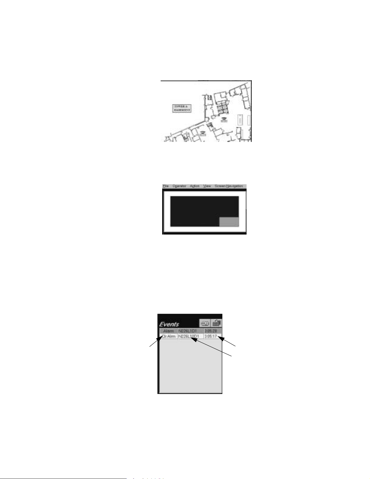
2.5.1.4 Graphic Floor Plan
The graphic floor plan is used to view the graphic layout of a building, high-r ise or campus type
settin g . It compris es the lar g est screen area in th e NCS. It will allow an oper ator to see a diagram
of any specific are a of the moni tored network and give the operator information abo ut the facility
area and the monitored devices. The graphi c screen is comprised of bitmaps with devices
overlaying them. Refer to Figure 2.6.
ncsbase.jpg
Figure 2.6 E xam ple of a Graphic Floor Plan
2.5.1.5 Key Map Area
The key Map Area is a n overvie w of t he graphi cs use d in the s yst em. It ca n be set up for na vigati on
or simply as an accompanying view of the foreground, refer to Figure 2.7.
2.5.1.6 Events Window
The Events window displ ays the first of 12 unacknowle dged, off-normal eve nts on the network.
The events are grouped by event type (i.e., fire alarm, sec urity alarm, supervisory alarm, and
trouble), and sorted by time within the group, displ aying the oldes t event first a nd the newest event
last. The highest event group is displayed on top of the window, the lowest event group on the
bottom of the window, refer to Figure 2.8. All events in this window are color coded. Fire alarms
are designated red, Security Alarm s as blue, Supervisory Alarms as orange, Trouble Conditions as
yellow, and Pre-Al arms as cyan.
The inform ation displayed consists of the event type, th e address, and the time that the eve n t was
received (assigned by the NCS). A detail button is provided to expand the ev ent box to display all
events, as well as pro vide more detailed inf ormation for each event. Refer to “The Detailed Ev ents
Window” on page 44 for more information on the Detailed Event Box.
Event Type
ncskeymap.tif
Figure 2.7 Key Map Area
Time
Address
firevent.tif
Figure 2. 8 Events Window
24 NCS Manual PN 51095:B1 3/08/02
www.PDF-Zoo.com
Page 25
NCS Graphical User Interface Programming
A device appearing in this box may be clicked on to dis play the graphic screen containing the
device. Any dev ice th at has been acknowl edged i s moved fro m the unacknowl edged e vent wi ndow
to the acknowledged event box.
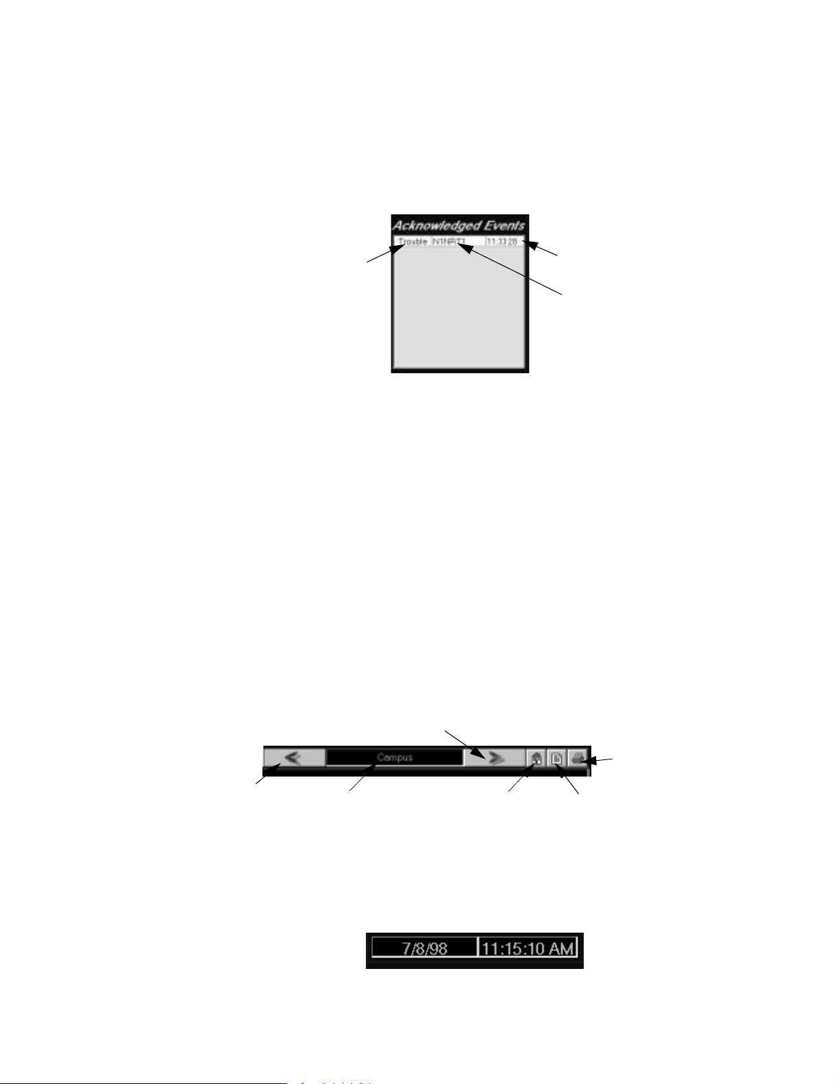
2.5.1.7 Acknowledge d Even t Box
The acknowledged event window displays the first 12 events on the network. The events are
grouped by event type (i.e., fire alarm, security alarm, supervisory alarm, trouble, etc. ), and sorted
by time with in the group, disp laying the oldes t eve nt firs t and t he n ewest eve nt la st. Refer t o Figur e
2.9.
The inform ation displayed consists of the event type, th e address, and the time that the eve n t was
received (assigned by the NCS). A detail button is provided to expand the event box and display
all events, as well as provide more detailed information for each event. Refer to “The Detailed
Events Window” on page 44 for more information on the Detailed Event Window.
A device appearing in this box ma y be clicked on to di splay the screen c ontaining the device. Any
events that have cleared from the device are deleted from the unacknowledged event box, unless
the clear event is an alarm condition that must be acknow l edged (i.e., a tra ck ing alarm on an
AM2020/AFP1010 that clears without a reset). In that case the clear alarm will move to the
unacknowledged e vent box for further action.
2.5.1.8 Screen Navigation Tools
Use the screen naviga tion tools to advanc e to different gra phic representation screens by using the
< and > arrows, refer to Figure 2.10. Click on the house icon to go direc tly to the “Home” page,
click the middle icon to open a Text File dialog tha t is associated with the Graphic Screen box, or
click on the last icon (printer) to print out a screen. In addition, the NCS provides a command to
display all screen names in a dialog box. Double-click one of the screen names to invoke the floor
plan specified.
Event Type
Figure 2.9 Example of the Acknowle dged Event Box
Time
ncsackn.tif
Address
2.5.1.9 Date / Time Field
NCS Manual PN 51095:B 1 3/08/02 25
www.PDF-Zoo.com
Forward Arrow
ncsnavig.tif
Back Arrow
Current Screen
Home Screen
(Top Level Screen)
Figure 2.10 Screen Navigation Tools
Text File Ass ociated
with Graphic Screen
Print Graphic
The Date / Time Field displays the current syst em time (a s set by Windows NT 4.0 Workstation)
within second resolution. This field is updated every second so the current time is always
displayed , refer to Figure 2.11. The NCS is completely Year 2000 compliant.
ncsdatime.tif
Figure 2.11 Date and Time Field
Page 26

Programming NCS Graphical User Interface
if
2.5.1.10 Logo Window
This window is used to dis play a company logo. This logo ca n be modified using the GSP and
PaintShop Pro to customize it to a particul ar installa tion.
2.5.1.11 Tool Bar
A tool bar is available on the right side of the Graphic Interface Screen. Buttons on thi s tool bar
are used to display the Event Counter and Detailed Event windows, refer to Figure 2.12. These
windows may also be accessed under the View Menu. Refer to “The View Menu” on page 43 for
examples of these windows.
Event Counter
Figure 2.12 Tool Bar
2.5.1.12 Alarm / Trouble / Supervisory Alarm / Security Alarm Banners
A set of five symbols are located in the upper right corne r of the NCS. These symbols represent
fire-alarms , s upervisory alarms, security alarms, trouble, and pre-alarm condi tions present in the
system, refer to Figu re 2. 13. If any of the s e unacknowledged events are present in the system, the
appropriate symbol will blink. If all events ha ve be en ac knowledged, the symbol will remain
steady. If the system is at ALL Systems Normal, the four symbols will be replaced by an All
Systems Normal message.
Supervi sory Alarm
Alarm
Security Alarm
Figure 2.13 Alar m, Trouble, Supervisory Alarm, Security Alarm and Pre-Alarm Banners
Trouble
2.5.1.13 Command Area
The command area at the top of the sc reen allows the user to SAR (signal silence, acknowledge or
reset), the networ k or a speci f ic node, refer to Figure 2.14. Pressing a button will transmi t the
appropriate command over the network. The user has the ability to vector the signal silence and
system reset comman ds to specific nodes on the network via a pop-up dialog box. The node
address currently on the network and within the users ability to S R (signal silence or reset) will be
displayed in this pop-up dialog box. In ad dition, another s election will be made available to SR all
off-normal nodes, or all nodes in the system. This will be user configurable in the NCS local
programming dialog box.
ncstoolb.t
Detailed Events
ncsbanr.tif
Pre-Alarm
26 NCS Manual PN 51095:B1 3/08/02
www.PDF-Zoo.com
ncscomnd.tif
Figu r e 2.14 Com mand Ar e a
The user has the option to select one, many or all panels to SR. Nodes to SR are limited by the
NCS programming and the individual password abi lity. The ability to vect or the acknowledge
command is not provided.
This dialog box is displayed when the cursor is over the Acknowledge, Signa l S ilence or Reset
button, and the right mouse button is cl icked. Pressing the si gnal silence and reset button with the
left mouse button bypasses the vector di alog box, and sends the appropriate command to all nodes
programmed into the system (or all off-normal nodes), and accessible with the users password.
Page 27

Menu Options for Programming Programming
Acknowledge
Initiating a acknowledge command will transmit a point acknowledge or block acknowledge
message to all ap propriate nodes. The nodes tra nsmitted to are limited by the nodes programmed
into the system and the user password level.
If the highest priority event in the system is a fire alarm condition, a point acknowledge message
will transmit to the node, acknowle dging the point. If the highes t priority event in the system is a
security alarm or lower event, a block acknowle dge command will be transmitted in the same
manner as in the Comma n d ar ea.
Any point acknowled ge or block acknowledge initiation commands will be logged in the history
manager and current eve nt window, if successfully completed. If this message co uld not be
completed, a error me s sa ge will be displayed to the user.
System Reset
Initiating a system reset comm a nd trans mi ts a system rese t messag e to all appr opri ate node s. The
nodes transmitt ed to ar e limited by the nodes programmed in to the system, the user pass word leve l,
and the nodes selected by the user.
The system reset in itiated command is logged into the history manager and current event window,
if successfully c ompleted. If this message was not com p leted, a e r r or message wi ll be displayed to
the user.
Signal Silence
Initia ti n g a si gnal silenc e co m m an d tr an smits a sig n al sil en c e m essage to al l ap p r o pri at e n o de s .
The nodes trans mi tted to are limited by the nodes programmed into the system, the user pa ssword
level, and the nodes selected by the user.
2.5.1.14 Current Operator F ield
The current operator field is a window that shows the name of the current operator of the NCS.
Pressing the (...) button to the right will display informat ion about the current operator. Refer to
Figure 2.15.
Figure 2.15 Current Operator Field
2.6 Menu Options for Programming
2.6.1 Administration Menu
The Administration menu (refer toFigure 2.16) gives the user acce ss to three commands: System
Setup, Network Operations, and the Archive History Database.
ncsoper.tif
2.6.1.1 System Setup
NCS Manual PN 51095:B 1 3/08/02 27
www.PDF-Zoo.com
ncsadmin.tif
Figure 2.16 The Administration Menu
When clicking on System S etup under the Administrat ion Menu, the user will gain acce ss to the
System Administra tion dialog box. In this dialog box there are five tabs: Genera l NCS , Us er
Account, Printer, Voice, and Graphic Configuration, all in which contain NCS programming
options.
Page 28

Programming Menu Options for Programming
e
t
,
General NCS Tab
This tab contai ns all NCS programming options which include Port A and Port B Thre sholds, the
speaker frequencies for Alarm and Trouble, the Time Sync options, a Data Refresh option, a UPS
Supervision opt ion , a single port or dual port s upervi sion in dic ation, a Res et/Sign al Si lence Option,
a History Backup opti on, a Master Time Keeper opti on (refer to Figure 2.17).
Click here to set th
NCS as the curren
time keeper, see
Figure 2. 18.
Clic k he r e to s et the
current system time
see Figure 2.19..
ncssysad.tif
Figu r e 2.17 Gen eral NC S Ta b
ncssetdate.jpg
Figu r e 2. 18 Setting the N C S as th e C u rr ent Tim e K e ep er
28 NCS Manual PN 51095:B1 3/08/02
www.PDF-Zoo.com
Figu r e 2.19 Se t ti n g Sy stem Time
ncssettime.jpg
Page 29

Menu Options for Programming Programming
User Account Tab
In the System Administration dialog box, the User Account Tab displays a Current Users list (refer
to Figure 2.20) where all user acc ounts currently setup on the NCS are displayed.
Add a user to
the NCS
Add or dele te
commands from
a user account
Delete a user
from the NCS
NCSfiu5.jpg
Figure 2.20 T he U ser Account Tab
This dialog box also lets t he us er add, edit and delete users from the NCS. To set up a new user on
the NCS, press the add user button. The new user dialog box appea rs, prompting for a new user
name (refer to Figure 2. 21). Enter a user name up to 19 characters long. Check boxes allow all
system commands or all available nodes to be assigned at once to the new user account. Press OK
to accept the new user name.
T o add or dele te commands from a user accou nt, pres s the edit user but ton. The account edit dia log
box appears with a listi ng of all commands and all nodes available on the NCS (refer to Figure
2.21). It is necessary to insert data into the screen fields that are marked with an asterisk.
NCS Manual PN 51095:B 1 3/08/02 29
www.PDF-Zoo.com
Figure 2.21 Editing User Information (General)
CSfiu7.jpg
Page 30

Programming Menu Options for Programming
Pressing a check box bes ide a command selects or deselec ts it from the user account being edited,
(Figure 2.22). All nodes available on the system are displayed in the acces sible nodes section.
Only highlighted nodes a re accessible to the user account. Pressing on a node selects or deselects
it. After editing the user account, press OK to ac ce pt the changes, (Figure 2.23). Initially only the
Administration Account user can edit accounts; however, any user given access to the Account
command will also have the abi lity to edit accounts.
Note: All no des assigned to a gi ven us er will have t he s am e s et of commands available to them.
To delete a user account from the NCS, highlight the account and press on the delete button from
the account li st dialog box.
Figure 2.22 Editing User Information (Permission)
Figure 2.23 Editing User Information (Nodes)
ncspermission.jp
ncsnodes.jpg
30 NCS Manual PN 51095:B1 3/08/02
www.PDF-Zoo.com
Page 31

Menu Options for Programming Programming
Printer Tab
In the System Administ ration dialog box, under the Printer tab the user can setup the
communications port settings if the printer is connected to a call port, refer to Figure 2.24. The
NCS supports two types of pri nter:
• An Event (line) printer that can be attached to the COM or LPT port for printing of all events
received by the NCS.
• A Gr a p hi cs Pr i nte r th at can be at ta ch e d to th e LPT Port f or pri n ti n g gr ap h ic s. If att a ch ed , it
must be set as the default printer.
Note: If a line and graphic printer are to be used by t he N CS, event printer mus t be connecte d to a COM port.
ncsprtab.jpg
Figure 2.24 The Printer Tab
Event Printer Setup - The event printer is usually connected to the seri al port, but can be
connected to the pa rallel port. The event printer is used to print all events as they are received by
the NCS. The printer will be activated as soon as the event is received. If the printer is connected
to a serial por t, certa in optio ns must be sel ecte d. The se incl ude the commu nicat ions po rt t he print er
is connected to, the BAUD rate, the parity, the number of data bits, and the number of st op bits.
These settings must match the settin gs in the printer itself. If the eve nt printer is connected to the
parallel port, these option s ar e not applicable.
The Printer itself mus t be set with the sam e options selected here. In addition, the compressed
mode of operation (17 c pi) must be selected. This is required so that an event can be printed on a
single line. If not selected, an event will wrap to the next line.
Graphics Printer Setup - the graphics printer is a laser printe r connected to the LPT port. The
setup for this printer must be done in Win dows. Any Windows NT 4.0 Workstation compatible
printer tha t will work connected to the parallel port can be used. This printer is to be used to print
screens, any history file, and any reports generated by the NCS.
Voice Ta b
There are two types of voice messages in the NCS. Those that are linked to an event or c ommand,
and those which are linked to a device. Files which are linked to events or comma nds must be in
the "W a ves" di recto ry. Files which will be li nked to a d evice must be i n the "Sounds" fil e dire ctor y.
Refer to Figure 2.25.
NCS Manual PN 51095:B 1 3/08/02 31
www.PDF-Zoo.com
Page 32

Programming Menu Options for Programming
Events and Comman d file s will be a ctiv ated aut oma ti call y when t he ev ent happ en s. Separ ate eve nt
files can be set up for:
• Alarm and Pre-alarm events.
• Supervisory and Security events.
• Trouble events.
• System Reset, Signal Silence and Acknowledge commands.
• Alter Status Commands (which include enabling or disabling a device and turning a module on and off).
• All Systems Normal (a message that can be invoked when the system returns to an all systems normal state).
If a higher priority event interrupts a lower priority ev ent, the current voice message will be halted,
and the new voice message will be started.
To select a w ave file
for an event, select
under the Wave File
directory. A dropdown menu will
supply the us er with
available w ave files.
ncsvoice.tif
Figure 2.25 Voic e Tab
Graphic Configuration Tab
Under this tab the us er ca n invoke the main screen on all sys tems normal, auto displ ay guidance
text, a uto display device document, pla y wave files, display device labels, and also print device and
guidance tex t and the graphic itself. Click in a box in order to put a check in the category you
would like to display or print. Refer to Figure 2.26 .
32 NCS Manual PN 51095:B1 3/08/02
www.PDF-Zoo.com
graphicstab.tif
Figure 2.26 Graphi c Configuration Tab
Page 33

Menu Options for Programming Programming
2.6.1.2 Network Operations
The Network Operations comm and located under the Administ ration menu opens a Network
Systems Window that allows the use r to s et up the nodes that the NCS will moni tor, check the
current state of all nodes programmed in, and access the read status and alter status menus for a
particular node.
The Network Systems Window displays the node number, node type, label, on-line status and
signal silen ce sta tus in a spread-sheet li ke view, refer to Figure 2.27. The node type is AM2020/
AFP1010, AFP200, AFP-300/400, INA, etc. The label is a 30 character custom label local to the
NCS that can be entered by the user. The on-line status is either on-line or off-line. The signal
silence status is N/A, Normal, Partial, or Full Silence.
ncsnetop.tif
Figure 2. 27 The Network Operations Menu Option
System Setup
The Network System wind ow allows the user to add, delete and edit nodes. The LOCAL NCS
cannot be deleted from the network system window. Upon initial powerup of the software, or if the
software powers up in demo mode, the local NCS will be programmed in as node 0. The operator
must change this node number to initiate network communicati ons. However, if the system is in
demo mode, the address cannot be changed. Nodes can be adde d or deleted from this list. Editing
a node will allow the user to enter the 30 character custom labe l, refer to Figure 2.28.
editnode.tif
Figure 2.28 Editing a Node Dialog Box
There is a second window available to the user which indicates the nodes that are present on the
network, but not programmed into the NCS. The information displayed includes the node number
and node type. Double-click on any nodes in the dialog box to program it into the NCS. The NCS
will only display events, act on, and comm unicate, with nodes that are programmed into the NCS .
NCS Manual PN 51095:B 1 3/08/02 33
www.PDF-Zoo.com
Another option ava ilable is to auto-program all nodes on the network once net work
communicati ons has been establi shed. This option will automatically add the node number, type
and status in this list.
Page 34

Programming Menu Options for Programming
Node Access
Double-clicking on a particular node in the network system window displays the initial read status
menu, if read sta tus is supported by that node. If it is n ot, an error message will be displayed, refer
to Figure 2.29.
nodemess.tif
Figure 2. 29 N ode Access Error Message
From the initia l read status menu, the user can now se lect further read stat us , alter status and
programming opera tions. Double-click on the loca l NCS for a display of the local set ting for the
NCS.
In addition, right clicking on a node in the network system window opens the Read Database
Menu, from which the user can c hoose to vie w loo p, zone , or de vice inf ormation. This inform atio n
is displayed in a spread sheet type format, and is re ad-only. The information is obtained from the
database which is store d on the NCS. Refer to Figure 2.30.
NOTE: THIS INFORMATION IS ONLY UPDATED DURING UPLO AD AND READ STATUS COMMANDS, AND THEREFOR E MIGHT NOT
BE UP-TO-DATE.
34 NCS Manual PN 51095:B1 3/08/02
www.PDF-Zoo.com
rdatamen.t if
Figure 2.30 Read Database Menu
Page 35

Menu Options for Programming Programming
2.6.1.3 Archive History Database
The Archive Hist ory Database menu option allows the user to archive the current history database ,
and open a new one, refer to Figure 2.3 1.
ncshist.tif
Figure 2.31 The Active History Database
2.6.2 Graphic Menu
The Graphic Menu op tio n is us ed to b ring y our gra phics c reate d in t he GSP i nto the NCS, or invok e
the Graphics Setup Program.
2.6.2.1 Graphic Setup
The graphics in the NCS are programmed using the Graphic Setup Program (GSP). This program
can be run from the NCS or executed as a stand-alone program. It is used to set up all floor plans,
device icons, links, etc. in the progra m. All graphics information is stored in graphics.mdb. Refer
to the Graphic Setup Program in the Operations section in this manual on how to use the program.
Refer to “The Graphic Setup Pr ogram” on page 60 for an in-depth explanat ion of the GSP.
2.6.3 Utilities Menu
The Utilities Menu allows the user to edi t speech files, comp act databases, and view networ k
communication statistics. The Edit Speech File opens up the Voice tab which also can be opened
through the Syste m Administration menu. The Compac t Database compacts and saves a dat abase
for transfe rring information onto a floppy disk. *Network Statistics allows the user to troubleshoot
network statistics as well as view them, refe r to F igure 2.34. The user can choose to vie w loca l or
remote devices or reset all nodes.
*The Network Statistics selection is only useful when consulting with a Technical Services representative.
graphmen.tif
Figure 2.32 The Graphic Menu
NCS Manual PN 51095:B 1 3/08/02 35
www.PDF-Zoo.com
utilitmen.tif
Figure 2.33 The Utilities Menu
Page 36

Programming Menu Options for Programming
ncsstats.jpg
Figure 2.34 Network Statistics
2.6.4 The Help Menu
The Help menu allows the user to ac cess a help file without exiting an applicat ion. The About
command displays a splash screen which shows the copyright and part number of the software
(refer to Figure 2.36).
ncshlepmn.jpg
Figure 2.35 The Help Menu
ncssysint.jpg
Figure 2.36 The System Interface Window
Select the System Info button to access information (memory, version, processor, etc.) about the
system you are on.
36 NCS Manual PN 51095:B1 3/08/02
www.PDF-Zoo.com
Page 37

Menu Options for Programming Programming
N
OTES
...
NCS Manual PN 51095:B 1 3/08/02 37
www.PDF-Zoo.com
Page 38

Operation Normal Operation
Section 3 Opera tion
3.1 Normal Operation
During normal operati on, when no fire alarms or troubles exist, the Graphic Interfac e window will
appear as shown below with an “All Sys tems Normal” message in top right-side of the window.
"All Systems Normal" message
ncssysnorm.jpg
Figure 3.1 S ystem Interface Window
The user can perform funct ions associated with the following butt ons without having to ente r a
password, these functions can be performed under the Action Menu or directly from th e Interface
Window.
3.2 T roubles
ACKNOWLEDGE - The Acknowledge button acknowledges events currently in the system.
Alarms are acknowledged individually, and troubles are acknowledged as a group (block
acknowledge). Receiving unit mode is not supported on the NCS and all nodes on the network
should be configured for block acknowledge.
SIGNAL SILENCE - The Signal Silence button si lence s all cont rol modules in t he syste m that are
programmed as silenc eable. The System Interface Window will reflec t that a signal silence is
requested.
RESET - The Reset button resets all fi re panels for the particular system in which it was requested.
When a trouble is receive d f r om a fire alarm panel it is report ed to the NCS. The NCS will report
the trouble i n th ree ways; the trou ble icon in the banner will flash , the t rouble wi ll be report ed in th e
Events window, and it will show up in the Event Counter s window. Refer to Figure 3.2.
38 NCS Manual PN 51095:B1 3/08/02
www.PDF-Zoo.com
Page 39

Alarms Operation
.
Trouble icon
flashing in the
Ban n er a r ea.
Trouble repo rted
in the Events
Counter Box
under New and
Tota l categorie s.
Detector
showing the
reported trouble
Trouble reported
in the Events
window.
ncstroub.jpg
Figure 3. 2 T roubles Reported to the NCS
Select Acknowledge to acknowledge that a trouble has been reported. The trouble will then be
shown in the Acknowled ged E vents window, seeFigure 3.3. Select Signal Silence to silence
NAC’s, and select Reset to reset the control panel.
Troubl e reported
in the Events
Counter Box
under the Total
category.
3.3 Alarms
Trouble icon
stops flashing in
the Banner area.
Trouble moves
to the
Acknowledged
Events window
ncstrouback.jpg
Figure 3.3 Ackn owledging Troubles on the NCS
When an a la r m is r ec ei v ed from a fir e al ar m panel it is re p orted to the N CS. The NCS wil l rep o r t
the alarm in three ways; the alarm icon in the ba nner will flash, the alarm will be reported in the
Events window, and it will show up in the Event Counter s window. Refer to Figure 3.4.
NCS Manual PN 51095:B 1 3/08/02 39
www.PDF-Zoo.com
Page 40

Operation Alarms
d
Alarm icon
flashing in the
Alarm reported
in the Events
Counter Box
under New and
Tota l categorie s.
Detector
showing the
rep orted alarm
Banner area.
Alarm reported
in the Events
window.
Alarm reported
in the Events
Counter Box
under the Total
category.
ncsalarm.jpg
Figure 3.4 Alarms Reported to the NCS
Select Acknowledge to acknowledge that an alarm has bee n reported. The alarm will th en be
shown in the Acknowledged E vents window, see Figure 3.5. Selec t Signal Silence to sil enc e
NAC’s, and select Reset to reset the control panel.
Alarm icon
stops flashing i n
the Banner area.
Alarm moves to
the Acknowle dge
Events window .
40 NCS Manual PN 51095:B1 3/08/02
www.PDF-Zoo.com
ncsalarmack.jpg
Figure 3.5 Acknowledging Alarms on the NCS
Page 41

Supervisory, Security, and Pre-Alarm Operation
3.4 Supervisory, Security, and Pre-Alarm
When a supervisory, security, or pre- alarm signal is receive d from the control panel it is reported to
the NCS. The NCS will report the supervisory, security, and pre-alarm in three ways; the
appropriate icon in the banner will flash, the supervisory, security, or pre-alarm will be reported in
the Events window, and it will show up in the Event Counters window.
Select Acknowledge to acknowl edge th at a supervis ory, security , or pre -alarm has been report ed: it
will then be shown in the Ack nowledged Events window und er its appropriate cate gory. Select
Signal Silence to silence NAC’s, and select Reset in order to reset the control panel.
3.5 Menu Options for Operating the NCS
3.5.1 File Menu
The File Menu (refer to Figure 3.6) allows for printer setup , or exi ting the NCS application.
ncsfilemen.jpg
Figure 3.6 The File Menu
3.5.1.1 Exit
The Exit command from the fil e m enu e xits the NCS program and places the user in the Windows
NT 4.0 Workstati on environment. The user i s prompted for a password. After entering the co rrec t
password a warning display indicates the user is exiting the NCS application (refer to Figure 3.7).
The user should either press Ok to exit the NCS application or press Cancel to abort.
Caution: Leaving the NCS app lication disconnects the NCS from Noti•F ire•Net which leaves the
!
building unprotected and the NCS not perform ing Life Safety functions.
Figu r e 3.7 The E xit Dial o g Bo x
3.5.2 Operator Menu
The Operator Menu allows the user to Login, Logout, and Change Password of the NCS, refer to
Figure 3.8.
ncsopmen.tif
Figure 3.8 The Operator Menu
ncsexit.tif
3.5.2.1 Login
NCS Manual PN 51095:B 1 3/08/02 41
www.PDF-Zoo.com
The Login command allows the user to gain access to the NCS by selecting his or her name in the
dialog box. Both a user name and a password are required to log on (refer to Figure 3.9). When
the NCS is first powered up, the in itial user name is Admin. After initial login, the Administration
Account passwo rd must be changed to something other t han Admin to ensure system security. The
administration account user shoul d then set up accounts with temporary passwor ds for all operators
that will be accessing the NCS. Passwords can be up to 19 characters long.
Page 42

Operation Menu Options for Operating the NCS
Asterisks are dis played in place of characters when entering a password. After selecting the user
name and entering the pa ssword, press Ok to accept the logi n information. If an error is made
while enterin g the password during login , a qui ck warning beep sounds, and the password dialog
box remains on the screen with the user name highli ghted.
ncslgout.tif
Figure 3.9 Login Dialog Box
3.5.2.2 Logout
The Logout command is used to exit the NCS . Once log out has been sel ected , a dia log bo x appear s
asking the user for the pass word. (refer to Figure 3.10). After ent ering the password, select Ok to
continue logging out. System commands will not be accessible again until a user logs onto the
NCS.
3.5.2.3 Change Password
The Change Password command al lows a user to change their curren t pass w ord. A password can
only be changed by the user who owns the password. Not even the Administration Account user
(the top user account with permanent access to all NCS commands) can change another user's
password.
When the Change P assword command is selec ted, the change pass word dialog box (refer to Figure
3.11) prompts the user for old and new passwords . Asterisks will appear in place of the entered
characters for bot h the old and new passwords. Type the old password. Type the new password
and then ret ype it in the confirm password box to verify the first en try. Press OK to accept the new
password infor ma tion.
ncslgout.tif
Figure 3.10 Logout Dialog Box
ncschpas.tif
Figure 3.11 Change Password Dialog Box
42 NCS Manual PN 51095:B1 3/08/02
www.PDF-Zoo.com
3.5.3 The Action Menu
From this menu, the use r can acknowledge events , reset the system, perform a signal s ilence, hide
Page 43

Menu Options for Operating the NCS Operation
offline e vents, show offline events and perform a data refresh, refer to Figure 3.12.
ncsactin.tif
Figu r e 3. 12 The Ac ti on Men u
• Ackn ow ledge - Allows the function of acknowledge to be performed across the allowable
network nodes.
• Reset - Allows the funct ion of system reset to be performed across the allowable network
nodes. The user can rese t all nodes at one time, all off-normal nodes at one time, or select
individual nodes of choice.
• Signal Silence - Allows the function of signal silence to be performed across the allowable
network nodes. The user can signal silence all nodes at one time, all off-normal nodes at one
time, or select individual nodes of choice.
• Hide Offline Events - Hides all offline events. F or example, if a node is dis connected from a
network with active events, then this selection will mask them from the graphic workstation.
• Show Offline Events - Displays all offline events. For example, if a node is disconnected
from a network with active events, this option will unmask offl ine nodes that have acti ve
events.
Data Refresh - Is manually initiate d from the NCS to update the off-normal points in the NCS.
This is also autom atically done when the NCS is powered up. The NCS has the capabi lity to
initiate a data re fresh to five nodes simultaneously to update point information as fast as possible.
These menu options can also be accessed from the NCS Interface Window, Refer to “NCS
Graphical User Inte rface” on page 22 where they are explained in gre ater detail.
3.5.4 The View Menu
From the View Menu, the user can see the number of events that have occurred from the Event
Counter windo w option, see a detailed lis t of all events, fire and non-fire from the Detailed Events
option, view t he l ast 1 ,000 eve nts th at have happen ed in the syst em from the Curr ent Events opt ion,
and disable devices (once the de vice is disabled, the user can enabl e it again by double-clicking on
the device, f rom the wind ow it self ) from th e Disabl e Devic es op tio n, vie w the His to ry Manage r and
UPDL (refer to Figure 3.13).
3.5.4.1 Event Counters
NCS Manual PN 51095:B 1 3/08/02 43
www.PDF-Zoo.com
ncsview.tif
Figure 3.13 The View Window Menu
The Event Counter wind ow contains the new and total events on the network. The informat ion
displayed in the win dow cons ists of fire alarms, pre-al arms, security alarms, supervisory alarms
and troubles. The new and tot al field areas are capable of displaying a five digit number. Refer to
Page 44

Operation Menu Options for Operating the NCS
Figure 3.14.
ncsecoun.tif
Figure 3.14 Event Counters Dialog Box
Event counters are not permanently displayed on the Graphics Screen but invoked when prompted
by the user.
3.5.4.2 The Detailed Events Window
The Detailed Events Window is an advanced Signal Display inte rface to networked panels . The
Detailed Event s Com mand is di splay ed fro m the View Menu in the Start -up W indow. The Detailed
Events W indow contains all of f-normal events, both unacknowledged and ackno wledged, that are
currently present in the system, refer to Figure 3.15. It is made up of two parts, “ Fire Events and
Non-Fire Events. ” Two buttons are provided to t oggl e betwe en these two parts of th e window. The
Fire Events window conta ins all events tha t are normally displayed by the fire panel in its display,
which includes al l alarm and troubl e condit ion s. Non-Fire Events consi st of all events that are only
reported to the history buffer and printer of the fire-panel, such as speaker circuits , and nonreporting control modules, as well as zone act ivation.
Select the blue button to view al l non-fire events.
Figure 3.15 The Detailed Events Dialog Box (Fire Event s Shown)
A scroll bar will be provided if more events are present in the system that can be displayed at one
time. The ev ents are sorted by ev ent type (fire alarm, security alarm, supervis o ry alarm , trouble,
pre-alarm, ac knowledged alarm, acknowl edged security alarm, acknowledged supervis ory alarm,
acknowledge d trouble, and acknowledged pre - alarm) and time. This dia log box will be displayed
in the same position as when previously closed. If left open, it will be refreshed every 6 seconds,
and only if new events of equal or lower priority were receive d by the NCS. If higher priority
events were received, this window would be updated immediately.
All information received from the node that the ev ent happened on will be displa yed in this box.
This includes the event type, the device type, the device label, the firs t zone referenced in the CBE
equation (for panels that provide this information), the first zone label (for panels that provide this
information ), the tro uble ty pe (for troubl e conditi ons), th e time a nd dat e (as signed by the NCS), and
a panel specifi c type index. This box will be upda ted during receipt of normal events, as well as
during a data refresh operation. In the lat ter case most of the information will not be available, and
only the information that is available will be displa yed. The NCS provides the ability to print all
events in the Detailed Event box.
detailev.tif
44 NCS Manual PN 51095:B1 3/08/02
www.PDF-Zoo.com
Page 45

Menu Options for Operating the NCS Operation
3.5.4.3 Current Event Window
The curren t e ven t w i nd o w co n ta in s al l n et w o rk an d local event s, as w el l as system m essages
received by the NCS. This ca n be manually invoked by clicking on the message button to review
the current events in the system. A maximum of 1000 events can be dis played in the system
message box (refer to Fig ure 3. 16), with the newest event displayed on the bottom of the window.
If more than 1000 events are reached, the oldest event will be delet ed. The events displayed in this
window are sorted by time and date, with the time column being displayed first. Events in this
window will be color coded, using the same color scheme as in the Unacknowledged Event Box.
ncscurrt.tif
Figure 3.16 Current Events Di alog Box
The user has the option t o leave this window on top. This window will also always be displayed in
the same position as when previously closed.
3.5.4.4 Disabled Device Window
The disabled devic e window conta ins all di sable d devic es in t he syste m. A disable d device can be
directly sele cted (double-clicked) from the list of events, and re-enable d. A confirmation dialog
box will be displayed, confirming the enable command. If the point enabled is a AM2020 or
AFP1010 zone, righ t clicking on the point will bring up another menu. This me nu will give the
user an option of using the Zone Enable or Group Zone Enable command for the zo ne. All zones
will be colored to make them stand out within the window.
3.5.4.5 History Manager
NCS Manual PN 51095:B 1 3/08/02 45
www.PDF-Zoo.com
ncsdisdv.tif
Figure 3.17 Disabled Devices Dialog Box
The Disabled Device window will only be refreshed whe n the de vice is disabled or ena bled, but at
a rate no greater than 6 seconds. This window will also be displayed in the same position a s when
previously cl osed. The NCS provides the abi lity to print all events in the disabled device window.
The user may select the History Manager Window from under th e View Menu. The History
Manager is a program that records all operator actions and all events (alarms and troubles) that
have occurred in the sys tem. Refer to Secti on 4 on page 52 for a detaile d desc ription of the History
Manager.
Page 46

Operation Menu Options for Operating the NCS
3.5.5 Screen Navigation
Under this menu option the user can view different graphic building representa tions which have
been setup by the Graphi c Setup Program. Select Next or Previously Viewed screens to vie w the
floor representations, see Figure 3.18. The user may perform this same function by press ing the <
and > arrows above the graphic , see Figure 3.19.
ncsarrow.tif
Figure 3.18 The Screen Navigation Menu
ncsarrow.tif
Figure 3.19 N ext and Previous ly Viewed Arrow Keys
3.5.6 Trouble with NCS and INA Equipment
Signals origin ating at the NCS and INA are transmitted to other reporting node s (i.e., NCS or
another INA) on the network. All local troubles are reported with the exception of node of f-line
conditions which depend on the local sett ings of the NCS or INA and are reported individually by
all reporting nodes.
Below is a list of trouble messages which are exclusive to the NOTI•FIRE•NET
™
network
environment.
Node XXX Communications Failure
The node is programmed into the system but does no t exist physically on the network, or the
node is physically attached to the network but is not progra mmed into the Command Center.
Communication Link Failur e in Port A
Data is not being received on network (MIB) Port A. This trouble is only reported if the node
is configured for dual port supervision.
Communication Link Failur e in Port B
Data is not b eing rece ived on ne twork (MIB) Port B. This t roubl e is o nly report ed if the nod e is
configured for dual port supervision.
Lan Communications Failure
The specifi c network node can no longer communicate with the rest of the network, indicating
a problem with the network connections (refer to Appendix A of this manual for more
information).
46 NCS Manual PN 51095:B1 3/08/02
www.PDF-Zoo.com
Page 47

Read Status/Program Operation
3.6 Read Status/Program
The Read Status fea ture of the NCS allows the operator to display the statu s of node s or devices
communicating on and programmed into the NOTI•FIRE•NET
AFP-400 devices are su pported for read status operati ons in this software release.
Detectors
To perform Read Status on a detector in the system, select the node the detector is connected to
from the Se lect Syste m dia log box. Se lect OK. A node di alog b ox appe ars. Se lect the Detec tor ta b.
Enter the address of the detector that is desired to perform Read Status. Select Program. The
Detector dialog box appears. This dialog box displays the current programming for the detector ,
the verification counter , percentage of alarm, and whether the detector is in alarm, trouble, or
disabled (refer to Figure 3.20).
™
. Only AM2020/AFP1010 and
NCS Manual PN 51095:B 1 3/08/02 47
www.PDF-Zoo.com
ncsdetread.jpg
Figure 3.20 Detector Read Status
Control and Monitor Modules
To perform Read Status on a module in t he system, select the node the m odule is connected to from
the Select System dialog box. Select OK. A node dialog box will appear. Select the Module tab.
Enter the addres s of the module desired to perform Read Status. Select Program. The Module
dialog box will appear. This dialog box displays the current programming for the module and
whether the module is in alarm, trouble, or disabled (re fer to Figure 3.21).
Page 48

Operation Read Status/Program
ncsmodread.jpg
Figure 3.21 Monitor Module read Status
Zones
To perform Read Status on an AM2020/AFP1010 zone in the system, select the node the zone is
connected to from the Select System dialog box. Selec t OK. A node dialog box appears. Select
the Zone tab. Enter the zone number desired to perf orm Read Status. Select Pr ogram. The Zone
dialog box will appear. This dialog box displa ys the current progr amming for t he zone and wheth er
the zone is in alarm, trouble, or is disabled (refer to Fi gure 3.22).
48 NCS Manual PN 51095:B1 3/08/02
www.PDF-Zoo.com
ncszonerd.jpg
Figure 3.22 Zone Read Status
Annunciator Points
Page 49

Read Status/Program Operation
To perform Read Status on an annunciator point, select the Annunciator tab from the Node dialog
box. Enter the address of the poi nt desired to perform Read Status. Select Program. The
Annunciator Point dialog box displays. This dialog box shows the type of annunciator point and
whether it is in Alarm, Trouble, or Off (refer to Figure 3.23).
System Data I
ncsannunrd.jpg
Figure 3.23 Annunciator Point Read Status
NCS Manual PN 51095:B 1 3/08/02 49
www.PDF-Zoo.com
ncssysdat1.jpg
Figure 3.24 System Data I Point Read Status
System Data II
Page 50

Operation Read Status/Program
ncssysdat2.jpg
Figu r e 3.25 System Da ta II Poin t R ead Status
System Data III
50 NCS Manual PN 51095:B1 3/08/02
www.PDF-Zoo.com
Figure 3.26 System Data III Point Read Status
Page 51

Read Status/Program Operation
Notes...
NCS Manual PN 51095:B 1 3/08/02 51
www.PDF-Zoo.com
Page 52

The History Manager NCS Integrated Operation
Section 4 The History Ma nager
The History Mana ger program is designed to directly integrate with the NCS, or operate as a standalone program that can be used to view the history file at any given time. On PCs that have the
NCS installed, the History Manager can only be invoked through the NCS .
4.1 NCS Integrated Operation
When the History Manager is invoked, the History database is opened and all events are shown,
refer to Figure 4.1. While the History Manager is running, and a new, higher priority event is
received as the current one, the History Manager automatically s huts down to display the new
event. If equal or lower priority events are received, the History Manage r will not shut down.
history.tif
Figure 4.1 Current History Database
To maximize operations while the History Manag er is running, new events of equal or lower
priority, will not automatically be show n. I nstead, a “Refresh Grid” button will indicate if new
events have been receive d. If this button is grayed out, the History Manager is showing all e vents
that have been receiv ed. If this button is not grayed out , then new event s have been rece ived by the
NCS, but are not currently being displayed by the History Manager. Once this button is pressed,
the History Manager will query the database to show the new events received, and vect or to the top
of the page and display them, re fer to Figure 4.2
Figure 4.2 R efresh Grid Button
refresh.tif
52 NCS Manual PN 51095:B1 3/08/02
www.PDF-Zoo.com
Page 53

NCS Integrated Operation The History Manag er
Stored History Files
The History Manage r, by default, displays the currently active history database. This is indicated
by the program in the tit le ba r. The user can open older history databases under the File menu,
Open Archived History Fil e command, refer to Figure 4.3. This operation will close the current
database and open the selected one . Th e His tory Manager will indicate that th e current history fil e
is no longer di splayed by showing t he path and file name of the current history database in the title
bar . See Figure 4.4 for an example of an archived history database.
archivhs.tif
Figure 4.3 Opening a Archived History File
NCS Manual PN 51095:B 1 3/08/02 53
www.PDF-Zoo.com
archive.tif
Figure 4.4 Exampl e of an Archived History Database
The current hist ory database can be re-opened by selecting the Current History File command
under the File menu. If the history manager is shut down and later re-opened, and an old history
database was prev iously sele cted, the dial og box wi ll be sho wn indica ti ng this. The dialog box will
then ask if the user wants to open the current history database, or continue with the one selected.
Operator List
The History Manager pr ovides an Operator List via a control tab on the main screen. This t ab,
when invoked, will display all operators who have logged on to the system and the last login time
and date. This list is part of the history dat aba se, and therefore will be c lea red whenever a new
history database is opened. Refer to Figure 4. 5.
Page 54

The History Manager NCS Integrated Operation
operlis.tif
Figure 4.5 Example of an Operator List Dialog Box
Number of Events
The number of entries in the history database is shown at all times. If a custom filter view is
selected, the number of entries will be equal to the number of events shown, refer to Figure 4.6.
numevnt.tif
Figure 4.6 Numb er of Events Shown on the History Database
Stand Alone Operation
In stand alone operation, the History Manager works similar to the NCS Integrated operation.
When the Histo ry Manage r is powe red up, a blank hi story fil e is i nitia lly displ ayed. T he us er has to
manually open any history file.
Custom Filters
The history manager will allow the operator to view the events using the following search criteria:
• All events
• All events while a specific operator was logged in*.
• All events by node number, loop number or device number*. They can be independently set.
• Events with a particular device status (fire alarm, security alarm, supervisory alarm, point or system trouble, module
activation, disabled device, operator log in in/out, system pr ogramming and ot her events)*.
• Events which happened between in a given time frame*.
• Events received by device types, including detectors, modul e s , zones, bell circuits, pan e l circuits and other devices.
54 NCS Manual PN 51095:B1 3/08/02
www.PDF-Zoo.com
Note: The events marked * may be combin ed w ith any other search criteria.
Searching and displaying events in the hist ory m anager won’t ad versely affect the NCS operatio n.
Any operation of this type is conducted as a low priority event. Refer to Figure 4.7 for an example
of search dialog box an d Figure 4.8 for a search showing only Administration logins .
Page 55

NCS Integrated Operation The History Manag er
custfilt.tif
Figure 4.7 Exam ple of a Search Dialog Box
NCS Manual PN 51095:B 1 3/08/02 55
www.PDF-Zoo.com
custadmn.tif
Figure 4.8 Example of a Search of Administration Logins Only
If the user selects a custom filter view, the History Manager will indicate this by highlighting the
“Custom Filte r” butt on. Ref er to Figur e 4.8. If t he user does n’t ha ve any c ustom fi lt ers a pplied, th e
“All Events” view will be displayed, and the "All Events" button will be highlighted. Pushing
either button will bring up the associate d sc reen.
Visible columns
This command di spla ys a win dow wit h all c olumn t ypes that c an be shown i n th e Hist ory Ma nager.
A column can be selected or deselected, thereby hiding i t from view. Each column can be resi zed
enabling the user to decide which columns they want to be shown, and the size of each column,
refer to Figure 4.9. These options are stored in the registry and invoked every time the History
Manager is powered up.
Page 56

The History Manager NCS Integrated Operation
viscolm.tif
Figure 4.9 Select Visible Co lumn s Dialog Box
Printing
The current history database, or any stored database, can be printed to the NCS Graphics printer
connected to the NCS. The Print command located under the File menu invokes the common
printer dial og box, (re fer to F igur e 4.10) enab lin g the sele ction of a pri nter. The printout consists of
the information shown in the history manager. Columns that are not visible, will not print out. If a
custom filter has been selected, only the events that are a part of the filter will be printed.
56 NCS Manual PN 51095:B1 3/08/02
www.PDF-Zoo.com
hisprint.tif
Figure 4.10 Print D ialog Box
4.1.1 History Backup
The history buff er may co ntain an unlimi ted number of ent ries . However , onc e the numbe r reache s
100,000 events, a dialog box will be di splayed. The dialog box wil l instruct the user to open a new
database and arch ive the current database.
The operator has th e abi lity to archive the current database for backup, and thereby create a ne w,
blank history buffer. This is done directly through the NCS, by using the Archive History
command under the Adminis tration menu. This command open s a dialog box to save the current
history database, with a .his extension (see Figure 4.11)
Page 57

NCS Integrated Operation The History Manag er
.
hisback.tif
Figure 4.11 A rchive History Dialog Box
Automatic History Backup
The NCS can be automatically setup to back up a history file when the NCS reaches a user
selectabl e num ber of en tries, with ranges from 10,000 to 100,000 events. In addit ion, the history
database can be backed up any day of the month, ranging from 1 to 28.
The current hist ory file will be saved to a file name made up of the current date with a “a” prefix,
denoting an auto ma tic backup. If more the one backup has occurred in any given day, a “01” will
be added to the file. For example, “a061298-1-.his” indicates the first file backed up automat ically
on June 12th, 1998. A “a061298 -2.his” file indicates that a second file was backed up that day.
The path and filename of the old history file will be saved in the new history file. All history files
are backed up in the \{install}\HistoryArchives directory.
4.1.1.1 Upload/Down load (UPDL)
The upload / download window is used to upload or download the database from a node. Options
are available to initiate uploads, downloads, sc hedule uploads, and abort any current acti ons.
Information about the node number, status indication and progress indication will be displ ayed by
the upload / download. Select UPDL under the View menu option and a Main Screen will appear
showing nodes and their completion percentage, refer toFigure 4.12.
NCS Manual PN 51095:B 1 3/08/02 57
www.PDF-Zoo.com
ncsudmain.jpg
Figu r e 4.12 Upload/Down load M ain Win d ow
Page 58

The History Manager NCS Integrated Operation
All upload / download messages that affe ct the operation are stored in the history window and
current even t window. This includes ini tiat ing the up loa d / downloa d proc ess, aborting the process ,
or any errors that will prohibit the proces s from completing successfully. A message will also be
stored in these windows if the upload / download has successfully completed.
Upload - Before an upload is initiated, th e NCS will query the user for a data base file to st or e the
received inf ormation in. All uploaded inform ation, including the database version, will first be
stored in the NCS run-time database. After the upload is complete, the NCS will copy the
information for the node upload from the run-time data base to the database sp ec ified by the user.
Refer to Figure 4.13 for an example screen of uploading nodes.
Select the [...] button to
choose a database.
ncsupload.jpg
Figure 4.13 Uploading Nodes Screen
If the database specified is an older versio n, an error dialog box will be displayed, indicat ing the
problem. The upload is not allowed to proceed at thi s ti me. The Verifire utility has the ability to
convert an older database format to the current database format.
Download - The NCS will query the user for a database to download. It will ope n the database
specified, a nd che ck the v ersio n. I f the dat abase v ersio n is ol d, the NCS will displ ay an e rror di alog
box indicating the problem. The user is not given the option to continue the download. Refer to
Figure 4.14 for an example of a downlo ad screen.
58 NCS Manual PN 51095:B1 3/08/02
www.PDF-Zoo.com
ncsudown.jpg
Figure 4.14 Downloading Nodes Screen
Page 59

NCS Integrated Operation The History Manag er
Note: The V erifire utility has the ability to convert an older database format to the current database format.
Scheduled Uploads - The NCS has the ability to schedule uploads on a monthly or “one shot”
basis. The one shot wi ll provide the abili ty to s chedul e a set of panel s to up loa d only onc e. Opt ions
will be made available for the startin g tim e an d which nodes to upload. If a monthly upload is
selected, the day and time must be specified. If a one shot upload is specified, the exact data and
time must be specified. All scheduli ng options, including dates, times, and nodes selected, will be
NCS database.
ncssched.jpg
Figure 4.15 Scheduled Uploads Screen
• Once Only Upload - This option will allow the user to upload a set of panels on a “one-shot” basis. A date and time for
the upload is entered and the NCS initiates the upload at that time.
• Monthly - The NCS has the ability to sch edule uploads on a monthly basis. The user can sel ect the day of the mon th
and time to upload. The N CS can then upload the spec ified set of nodes every month at the specified time. To alleviate
the problem of how many days are in a month, the plug-in only allows a r a nge of 1 - 28 for the day s pecified.
• Multiple Panel Upload - The NCS has the capability of uploading or downloading up to five nodes at a time.
NCS Manual PN 51095:B 1 3/08/02 59
www.PDF-Zoo.com
Page 60

The Graphic Setup Program Program Layout
Section 5 The Graphic Setup Program
The Graphic S etup Program allows the creation of floorplans and devices as well as associating
information about each device.
5.0.1 NCS Integrated Operation
If the GS P is called up from the NCS, all operations are identical. However, when the GSP is
exited, gra phics .mdb is not aut omati call y upda ted. I ns tead, the da tabase c an be u pdat ed in th e NCS
using the Upd ate Graphic Databas e command under the Graphics menu. If t he NCS is not running
at the time the database is updated, the database can be updated once the NCS is powered up, and
the update command is executed.
In both the Standalone and NCS integrate d operations, on power -up the existence of the backup
database will be checked. If it exists, then a dialog box will be displayed indicating that it was
found. The user then has the option to use this database, or the graphics data base. If the graphics
database is chosen, recent edits might be lost.
5.1 Program Layout
The Graphic Setup Program (GSP) consists of several different windows. The main graphics area
and key-map area hav e the sa me si ze and location as in the NCS. This allows the user to place
screen floorplans and devices, and see them exactly as they would appear in the NCS. Refer to
Figure 5.1.
Menu Bar
Key-M a p A r e a
Graphics Are a
Title Bar
Figure 5.1 Graphic Setup Program Interface Window
Information Window
Toolbar
Tree View Window
(Screen Device View)
ncsgspint.jpg
In addition, the top are a has room for displaying the current screen information and command
buttons. The area to the right of the main graphics screen contains the Tree View Window whic h is
similar to a Windows Explorer type structure, refer to Figure 5.2. The Tree View Window offers
three different views of the system:
60 NCS Manual PN 51095:B1 3/08/02
www.PDF-Zoo.com
Page 61

Program Layout The Graphic Setup Program
5.1.1 Floor Plan Tree View
This view shows how the different screens are linked through groups. A path from the left to the
right identifi es screens containing lower groups, down to the floor plan containing only devices.
This view can also be used to navigate through the screens. Double-cli ck on a fl oor plan name to
display the appropriate floor plan. Refer to Fig ure 5.2.
ncstree.jpg
Figure 5.2 Floor Plan Screen Tree V iew Example
5.1.2 Group Tree View
This view shows which devices are linked to a group. The groups and devices associated with the
group are shown. Double-clicki ng on an item in this view will bring up the appropriate dialog box
to change any settings. Refer to Figure 5.3.
ncsgrview.jpg
Figure 5.3 Group Tree View Example
5.1.3 Floor Plan Device View
This view shows all screens in the system, and the devices associated with a screen, which includes
information labe ls and navigationa l buttons. Double-clicking on a floor plan displa ys the screen,
double-clicking on a device displays the edit dialog box for the device. Refer to Figure 5.4.
ncsscview.jpg
Figure 5.4 Floor Plan Device View Exam ple
5.1.4 Information Windows
The Information Window contain s the infor mation about the current screen that is edited . This
includes the screen Description, keymap file name, guidance text file name, and floor pl an file
name. Refer to Figure 5.5.
NCS Manual PN 51095:B 1 3/08/02 61
www.PDF-Zoo.com
Page 62

The Graphic Setup Program Program Layout
infowin.jpg
Figure 5.5 The Information Window
Double-cl icking on any o f thes e fi eld s dis plays a fi le dialog bo x. T his a llo ws the us er to chan ge t he
keymap or floor plan, select a new guidance text file, or change the name of the screen that is
currently edited, refer to Figure 5.6 for an example. If a floor plan is changed, a “Save Screen”
option appears, refer to F igure 5.7, allowing the user to save all current changes. This option only
appears if change s have been made to the current screen. In addition, double clicking on the floor
screen name in the Tree View Window also sa ves any current changes tha t have been made.
selectfl.jpg
Figure 5.6 File Dialog Box
savescrn.jpg
Figure 5.7 Save Screen Option Dialog Box
5.1.5 Tool Bar
A toolbar is availa ble through the Information Window. This toolba r is not res tricted to the
Information Window and can float to other areas of the screen. The toolbar contains shortcut
buttons for various graphic operations, including: creating groups, detectors, modules, zones,
information label s and na vigati on bu ttons , crea ting hot keys (ho t te mpla tes) and edit ing a floor pl an
or key map. Refer to Figure 5. 8.
Create Detector
Create Group
Create Zone
Create Module
Create Information Label
Create Navigation Button
Edit File Plan
Display Hot Keys
toolbar.jpg
Edit Keymap
62 NCS Manual PN 51095:B1 3/08/02
www.PDF-Zoo.com
Figure 5.8 Tool Bar
Page 63

Graphic Floor Plans The Graphic Setup Program
If a template group is defined, then pressing the short cut butto n will display a dialog box from
which a template can be chosen. If a template is not defi ned, then the first 40 items in the director y
will be displayed in a picture box. For example, if the Create Zones Button is pressed, and no
templates are de fined, the first 40 icons found in the device directory will be displayed in a pict ure
box. However, if templates are defined, a selection of all zone templates will be shown. After a
template is chosen, only the icons associated with that template will be displayed. Select a toolbar
icon and a library of icons assoc iated with t hat button will appear. Choose an icon by clicking on it
and dragging it to a lo cation on the floor plan screen.
5.2 Graphic Floor Plans
Floor plans are bitmaps that are displ aye d on the main screen of the NCS. The bitmaps measure
780 x 538 pixels and are customi zed thro ugh Pai nt Shop Pro, a thi rd pa rty program that i s packag ed
with the NCS. All floor plan bitmaps must be stored in the directory \{in stall}\Floors. All images
saved with Paint Sh op Pro must be saved in bitmap formats, not as the default .psp extension.
5.2.1 Adding Floor Plans to the NCS
A floor plan can be added to the NCS by selecting the Screens menu option, New Screens
command from the menu ba r. A confirmation dialog box is then displayed. This dialog box allows
the user to select an existing floor plan and keymap, or create a new floor plan and key-map. In
both cases, a floor plan title must be selected. Refer to Figure 5.9.
NCS Manual PN 51095:B 1 3/08/02 63
www.PDF-Zoo.com
floorpl.jpg
Figure 5.9 “N ew Screen” Dialog Box
If an existing floor pla n or keymap is to be a dded, a dialog box appears allowi ng the user to select a
floor plan, refer to Figure 5.10 for an example. Once the floor plan and keymap are selected, they
will be displayed in the Graphic Setup Program.
floorpic.jpg
Figure 5.10 Exis ting Floor Plan Di alog Box (Example)
Page 64

The Graphic Setup Program Graphic Floor Plans
If a new floor plan or keymap is to be added, a bla nk floor plan and key map will appear with the
floor plan title. This floor plan can be alte red e ntirely in PaintShop Pro, or in other graphic
programs such as Paint and then pasted into the scre en. Double-clicking on a floor plan or keymap
will invoke PaintShop Pro where any changes or ed its can be made to the drawing. When
PaintShop Pro is exite d, the file date and time are checked on the hard drive. If the date or time of
the file has chang ed, the bitmap is copied over the existing floorplan and displayed in the GUI.
Each screen contains a floorplan, keymap, screen description and guidance text. Although each
floor plan ha s a corresponding num eric identifier assigned to it, only the screen name is displayed
on the NCS main form. The Graphic Setup Program displays the name of the current screen, as
well as the floor plan filename, the keymap filename, and the guidanc e text file name that is
associated with the screen.
5.2.2 Selecting Floor Plans
The screen selecting command displays a dialog box which contains all screens with their
corresponding floor plan number, and a preview window. It allows the user to select a floor plan
for editing purposes. Onc e a screen floor plan has been selected, click the OK button and the new
floor plan with all it s associations will be displayed, refer to Figure 5.11.
selflpln.jpg
Figure 5.11 Selecting Floor Plans Dialog Box
5.2.3 Deleting Floor Plans
The Graphic Setup P r ogram allows the operator to dele te screens. When this operation is selected,
a dialog box containing all screens in the GSP, with the corre sponding floor plan numbe r, will be
displayed . In addi tion, this dialog box will contain a preview of the floor plan belongin g to the
screen that is to be delet ed, refer to Figure 5.12.
delscrn.jpg
Figure 5.12 Deleting Floor Plans Dialog Box
A confirmation dialog box will be displayed be fore the floor plan is actually deleted from the
system, refe r to F igur e 5.13. Dele ting a flo or plan caus es all dev ices, infor mati on labe ls, nav iga tion
buttons, etc. that are on the screen, to also be deleted. The physical bitmap files for keymaps and
floorplans ar e not de leted.
64 NCS Manual PN 51095:B1 3/08/02
www.PDF-Zoo.com
Page 65

Graphic Floor Plans The Graphic Setup Program
delsrdi. jpg
Figure 5.13 Deleting a Floor Plan Confirmation Dialog Box
5.2.4 Setting Keymap Links
A key map can be linked to a floor plan diagram if desired. In the NCS, when an area in th e key
map is double-c licke d, the sc reen li nked to the ke y map will appea r . This a llows e asy naviga ti on of
the graphics.
Keymap links can be set under the Screens menu, Set Keymap L ink command. When this
command is activated, a dialog box appears, dis playing all screens in the system, refer to Figure
5.14. Once the keymap and scre en are linked, the floor pl an will be displayed when the
corresponding keym ap area is selected.
gspkeymplk.jpg
Figure 5.14 Selecting Keymap Link s D ialog Box
5.2.5 Screen Title
The screen title describes the present screen. A 40-character floor plan title can be entered. All
screen titles ar e available for viewing and navigating from the Tree Vi ew Window.
5.2.6 Guidance Text
Guidance Text can be added to any screen. Guidance text may contain instruction or warnings
applicabl e to the displayed area. The text is entered using the guidance text viewer/editor, refer to
Figure 5.15. The gui dan ce text c an be print ed automati call y or b y devic e act ivati on fro m withi n th e
NCS or manually by user selection. To manually print guidance text by user selection, press the
button to display, choose auto display, and select aut o print.
textfl.jpg
Figure 5.15 G uidance Text Dial og Box Example
NCS Manual PN 51095:B 1 3/08/02 65
www.PDF-Zoo.com
Page 66

The Graphic Setup Program Keymap Area
5.3 Keymap Area
Keymaps are bitmaps whi ch are created and assigned during the new screen process. The bitmaps
measure 327 X 167 pixels. Keymaps are displayed above the floor plan on the Main NCS screen.
The Keymap acts as an overview for the floor plan it belongs to. Every floor plan must have a
keymap assigned to it, although the same Keymap may be assigned to different screens. Ke ymaps
can be customized through Paint Shop Pro. If a keymap link has bee n created, double-click the
keymap while in the NCS to bring up the associated screen.
5.4 Menu Bar Options
5.4.1 File
Select Exit Setup to close the Graphic Setup Program and return to the NCS, see Fig ure 5.16.
gspfile.jpg
Figure 5.16 The File Menu
5.4.2 Screens
Under the Scre ens m enu option, t he user can creat e a new graphic scre en, select a previous graphic
screen, delete a graphic screen or set a keymap link to a graphic screen, see Figure 5.17.
5.4.3 Devices
gspscreen.jpg
Figure 5.17 The Screens Menu
gspdevice.jpg
Figure 5.18 The Devices Menu
gspdevgr.jpg
66 NCS Manual PN 51095:B1 3/08/02
www.PDF-Zoo.com
Figu r e 5.19 Groups
Page 67

Menu Bar Options The Graphic Setup Program
gspgrpsetup.jpg
Figure 5.20 Setting Up Groups
Figure 5.21 Detectors
Figure 5.22 Modules
gspdevdet.jpg
gspdevmod.jpg
NCS Manual PN 51095:B 1 3/08/02 67
www.PDF-Zoo.com
gspdevzon.jpg
Figure 5.23 Zones
Page 68

The Graphic Setup Program Menu Bar Options
gspdevinfol.jpg
Figure 5.24 Information Labels
gspdevnb.jpg
Figure 5.25 Navigation Buttons
5.4.4 View
The View menu op tion allows the user to customize the tool b ar to the users preference and v i ew
screen statistics. Screen statistics include: device (detectors, modules, zones) count, graphic
(labels, navigation buttons) count and a Total count (c ombination of both).
gspview.jpg
Figure 5.26 The View Menu
5.4.5 Setup
The Setup menu allows the user to edit the site logo in Paint Shop Pro.
setupmenu.jpg
Figure 5.27 The Setup Menu
68 NCS Manual PN 51095:B1 3/08/02
www.PDF-Zoo.com
Page 69

Device Icons The Graphic Setup Program
5.4.6 Help
gsphelp.jpg
Figure 5.28 The Help Menu
5.5 Device Icons
After a floor plan and keymap scre en ha ve be en created, Device Graphics ca n be add ed. Device
Graphics include Level1 Groups, Level2 Groups, Devices (detectors, modules and z ones),
Navigation Buttons, and Information Labels. All device bitmaps must be stored in the
{install}\ device directory, Groups must be stored in the {instal l}\group directory.
5.5.1 Devices
A symbol can be use d to graphically represent a devi ce (detector, module or zone) in the fire alarm
system. In addition to a graphical represent ation of the device, the us er ca n assign device
descriptions and link pictures , documents and sound to the device. The NCS does not permit one
device to be displ ayed on multiple screens ; a dev ice can only appear on one screen .
A new device can be added to the sys tem by using the Devices Menu command or th rough the
toolbar. When using the tool bar, select the appropriate det ector, module or zone you would like to
add. After this comman d is exec uted, a library of icons will be displayed to select a symbol
representing the device, refer to Figure 5.29.
detbox.jpg
Figure 5.29 De tector Library of Icons
Once a device is selected, a new device dial og b ox is displayed where the user can enter address
information about the devic e, Figure 5.30 . For detec tors , modules and zones, opt ion s are avail able
to link a sound file, document and/or picture to the symbol. In addition, each of these devices can
be linked to a group. If grouping is to be used, the groups and gr oup screens should be creat ed
before a ctual devices. Devices can also be set to auto- vector , in this case the Auto-Navigate option
must be selected.
NCS Manual PN 51095:B 1 3/08/02 69
www.PDF-Zoo.com
Page 70

The Graphic Setup Program Device Icons
newdetbx.jpg
Figure 5.30 New Detector Dialog Box
The active icon wil l blink during an active condition, and steady when acknowledged. Once the
point returns to norm al, t he normal bit map is d ispla yed. The trou ble, d isabl ed dev ice a nd pre-al arm
icons also op e r at e th e s a m e w ay.
5.5.2 Detectors
Detectors have other symbols associated with them; an active icon, a trouble icon, a disabled
device icon and a pre-alarm icon. The appropriate icon will be displayed for an event, the devic e
label blinks if an event is unacknowledged, and is steady if the event is acknowledged.
5.5.3 Modules
Modules show an active , trouble and disabled device symbol. If the module can be disabled from
the NCS, the Disable Dev ice opti on must be chosen. If the module is an outpu t module , and can be
activated f r om the NCS, then the Control On/Of f option must be chosen.
5.5.4 Zones
A zone shows an active and disabled device symbol.
5.5.5 Linked Files
Sound, document and picture files can be linked with a device. To access these files through the
NCS software, the files must be in specific dir ectories on the PC.
• Pictures (scanned photos) must be in the {install}\Pictures directory.
• Text files (instructions etc.) must be in the {install}\docs directory.
• Soun d files (verba l instructions or warnings ) must be in {ins tall}\Sounds director y.
These files can also be manually activated by the operator.
5.5.6 Information Labels
Information labels are bitmaps that can be ad ded to a floor plan for additional information. These
labels are generally symbols representing biohazard, f lammable or other important information,
refer to Figure 5.31. Information labels do not receive information regarding alarms and troubles
from the system fro m the system.
70 NCS Manual PN 51095:B1 3/08/02
www.PDF-Zoo.com
Page 71

Device Icons The Graphic Setup Program
infolbl.jpg
Figure 5.31 Information Labels Dialog Box
To add an information label under the De vices menu option, s elect the Information Label option to
the New Information L abel c ommand, or select the info rmati on la bel ic on on the to olba r . Afte r this
command is executed, a library of icons will be dis played to select a symb ol representing the
information labe l. If templat e groups are defined for tha t label , then a group must be chosen before
a label is selected. Once a label is selected, a new label dialog box will be d isplayed where the user
can enter text information about the information label.
Double-clic k on a device label icon and drag it to the c orresponding area o n the graphic floor plan,
it will then appe ar on the screen. Double-cli ck on the information la bel in the NCS to display the
text file associated with the information label. Information labels can be moved around the screen
without being deleted and recreate d.
5.5.7 Navigational Buttons
Navigationa l Button s can b e plac ed anywhe re on a graphic scre en. Th ese butt ons are then li nke d to
other screens in the NCS. Place the cursor over a navigational button to see the la bel of the floor
plan associated with that button.
To create a navigational button link, sele ct the Navig ational Butt on icon on the toolbar or select the
Devices Menu option, New Navigatio n Button. A dialog box will appear that contain a navigation
button, refer to Figure 5.32. Double-click on the button and drag it to the appropriate area on the
graphic floor plan. After the navigation button is dragged on the screen a nother dialog box will
appear allowing you to s et up a link, refer to Figure 5.33.
navbut5.jpg
Figu r e 5.32 Navigati o n Bu tt on Dialog Box
NCS Manual PN 51095:B 1 3/08/02 71
www.PDF-Zoo.com
Page 72

The Graphic Setup Program Device Icons
navbut2.jpg
Figure 5.33 Set up Links Dialog Box
5.5.8 Delete Operations
To delete a particular button, device or inform ation label from a screen, place the mouse over the
symbol and right-click on the mouse (or use the Devices menu option, delete module, detector,
zone, etc.). A dialog box will appear allowing the user to delete a symbol .
5.5.9 Searching for Specific Items
Once many screens are entered, finding a particular device with out displaying each floor plan is
diffic ult. T he NCS has a Find comm and loca ted unde r the Devi ces me nu option, under ea ch devic e
category, which allows the user to find a device by ente ring in its device label or address Refer to
Figure 5.34. Once the label or address is entered, the appropriate floor will be invoked. For easier
viewing, selec t the Flash Label checkbox to m ake the device blink for two seconds. For
information labels and navigation buttons, the option to blink the graphic is given (no labels for
these).
indcom.jpg
Figure 5.34 Example of a Find Dial og Box for Detectors
5.5.10 Rules for Setting Up Device Graphics
The following rules must be followed when setting up device graph ics.
• A Level 1 Group must be created before any Level 2 Groups.
72 NCS Manual PN 51095:B1 3/08/02
www.PDF-Zoo.com
• Groups must be created before their associated devices.
• A floor Plan containing Level 1 Groups can conta in any Graphic Device.
• A Level 2 Group should not be placed on a screen where a Level 1 Group resides.
• Any Floor Plan can contain a Navigational Button, which functions as a link to another Floor Plan.
• Any floor Plan can contain Information Labels, which display te xt when double-clicked.
• If any Groups are created (or exist alr ea dy when beginning an edit session), the default autovectoring setting is set to false.
Page 73

Groups The Graphic Setup Program
5.6 Groups
Groups allow the creation of screen hierarchies for di splaying the pathway to an off normal device,
starting at a top level site view. Two levels of grouping, Level 1 and Level 2, are use d to as sociate
devices with a single bitmap. A Level 1 group can have eithe r Le vel 2 groups or actual devices
associated to it. A Level 2 group must be associated upwards to a L evel 1 group (in the floor plan
hierarchy), and will have devices assoc iated below it. The two levels of grouping plus the floor
plan where the actua l off-normal device is located offer three ma in view levels for floor pla n
navigation. These levels coupled with Nav igation Buttons offer a variety of setup possibilities for
graphics.
The graphics are no l onger l imite d to one t op screen , ther efor e the “H ome Scree n” is the fi rst sc reen
created. This screen is sho w n on NCS / GSP S tartup. This abili ty to have many top screens means
that Level 1 Groups can exist on different screens, each representing the Top Screen of a different
graphic path.
5.6.1 Level 1 Groups
A Level 1 group requires a normal s tate bitmap and a descript ion. A label is created from the
Group descript ion and displayed bottom center of the group bitmap. This label flashes when an
off-normal event is received for an associated device. The flashing occurs by alternating the
normal group description with the color and text of an off-normal event. Optional active and
trouble bitmaps can be assigned to a group for the se conditions.
5.6.2 Level 2 Groups
A Level 2 group requir es a n as sociat ed Le vel 1 group name, normal state bi tmap , and a de scrip tion.
An optional acti ve and trouble bitmap can be assigned and displayed when any off-normal
conditions occur for the group. T he Level 1 groups are selected from an available list box. If no
Level 1 groups exis t, an error message is dis played and the Level 2 setup is cancelled .
A label is created from the group description and displayed botto m center of the group bitmap.
This label will fla sh wh e n an off- n o rm a l ev en t is re ceived fo r an ass o c ia te d dev i ce. The flash i n g
occurs by alterna ting the normal group description with color and text of an of f-normal event.
5.6.3 Group Setup Restrictions
The following are restri ctions for groups:
• If a device on a floor plan is associated with a group, then all other devices on that floor plan
are automatically restricted to the gr oups contained on the screen where the associated group
resides. In other words, if L1D1 is associated with a specific group 2, then L1D2 on that floor
plan must also be associated with group 2, or another group on the screen where group 2
resides.
• Screens can contain group 1 icons or group 2 icons , but they can not be inter mi xed. If a floor
plan has a group defined, all other groups on that floor plan must be of the same level, either
Level 1 or Level 2.
5.6.4 Group Navigation
If a device goes into alarm or trouble, while auto-vectoring is off and a floor plan is displayed that
contains the device li nked, t hen the scre en with the group con tainin g the devic e where the event has
occurred will appear and the group label wil l flash. This can indicate that an off-normal condition
has occurred within the area that the group monitors. Double clic king on the group will either
invoke the fl oor pl an cont aining a Level 2 g roup (a ssumi ng that the firs t group was a l evel 1 group) ,
or the device that is off-normal. If a Level 2 group is defined, then the floor plan co ntaining this
group will be invo ked, and change to its off-normal bitmap. Double clicking now will invoke the
off-normal device.
NCS Manual PN 51095:B 1 3/08/02 73
www.PDF-Zoo.com
If the device is di rectl y linked to the top leve l group, t hen do uble-c licki ng on the device wil l inv oke
the floor plan that contains that group.
Page 74

The Graphic Setup Program Setup Templates
5.7 Setup Te mplates
Templates can be defined to make device setups easier. Templates can be defined to group a
number of device graphic file options together, or to define a Hot Template which contains the
same bitmap and opti ons for the device.
5.7.1 Template Groups
A template contains specific bitmap file groupings for modules, detectors, zones, information
labels, groups , and na vi gation bu tto ns. These t empla tes ca n be shown on the main s creen , and used
to drag items on the screen. They are des igned to logically group specifi c devices on a dialog box,
with each icon shown. A maximum of 40 icons ca n be s hown per template.
When creating a template, a dialog box listing all items in the directory is displayed. Select th e
checkbox next to the items to add them to the template.
5.7.2 Hot Templates
A hot template is a setup of specifi c m odules, detectors or zones. Once a devi ce has been added to
a screen, a n option within the device setup s aves it as a hot template. These hot templa tes can then
be used to set up other devices with the same options. The hot templates saved can be invoked
from the toolbar.
Note: If a device that defines a hot template is deleted, the hot template will also be deleted.
A hot template is defined for a specific device, (the hot template and the device are actually one item).
This allows the user to easily copy information from one device to another. Once the information for
a device hot template is changed, all new devices created from it will have the new information.
Devices created with the hot template before it was changed will not contain the new information.
5.8 Custom Bitmap
The bitmap that appears on the NCS main window next to the keymap area can be customized.
Changes to thi s bi tmap can be done through Pain tS hop Pro. To call up this file under the Setup
menu select the Edi t NCS Gr aphic command. When the graphics are updated, chan ges to the
Custom bitmap are al so updated. Refer to Figu re 5.35.
74 NCS Manual PN 51095:B1 3/08/02
www.PDF-Zoo.com
editncsg.jpg
Figure 5.35 Example of Editing a Bit m ap in PaintShop Pro
Page 75

Template File s The Graphic Setup Program
5.9 Template Files
For the creatio n of blank floor plans, a nd invoking PaintShop Pro, several files a re required for the
program to operate correctly. These files can not be delet ed. If they are missing, the program will
not operate correctly.
5.10 NCS Required Files
3. Floor Direct ories
{install}\Floors\Genfloor.bmp
\Olefloor.bmp
\NotProgF.bmp
4. Ke ym a p Direc t o ri es
{install}\Keymaps\Genkey.bmp
\Olefloor.bmp
\NotProgK.bmp
5. Device Directories
{install}\Device ...Detector, Module, Zone BMP’s
\Group...Group BMPs
\Inflabel...Device Information label BMPs
\Navigate. ..Device navigation button BMPs
\Pictures...Device associated bitmaps
\Sounds...Device wave files
\Docs...all text files
Note: Groups and Group s creens should be created firs t if grouping is to be used.
NCS Manual PN 51095:B 1 3/08/02 75
www.PDF-Zoo.com
Page 76

Windows 2000 Security Disable Procedure Disable Procedur e
Appendix A: Windows 2000 Security Disable Procedure
A.1 Disable Procedure
In the W indows 2000 environment, a log-on box is displayed requesting a user na me and password
each time Windows 2000 starts up. The Windows 2000 log-on box may be disabled if the NCS
software login function is sufficient for security or if the NCS software is to start automatically
once Wi ndows 2000 is running. Once the NCS software starts, the user must still choose Login
under the File menu and enter a user name and password to ga in access to the NCS. Note: The
Login function in the NCS software can not be eliminated. To eliminate the Windows 2000 log-on
box, execute the fol lowing steps:
1. From Program Manager, go to the File menu (for W ind ows 2000 us ers , sel ect S tart, the n Run) .
Select Run and type rege dt32. This brings up the Windows 2000 Registry.
2. Go to the HKEY_LOCAL_MACHINE dialog box.
3. Double-click on Software, then on Microsoft.
4. Double-click on Windows 2000, followed by Current Version, and then Winlo gon. At this
point the screen will be split into two sections. The section on the left side contains the tree
structure of the registry and the right side contai ns values stored in the registry.
5. From the Edit menu, select Add Value. A dialog box wil l pop up. Under Value Name, type
DefaultPassword (do not change the displayed data type).
6. Press OK. Another dialog box will pop up. Under String, enter the cu rrent password of the
NT admi n istrato r. The password is ca s e sensit iv e , s o b e su r e it is entere d corre ct ly. Press OK
for the change to ta k e effect.
7. From the Edit menu, selec t Add Value again. Under Value Name, type AutoAdmi nLogon.
Press OK. Under String, enter 1 (do not change the displayed data type).
8. Verify that the two new variables ente red in the previous steps appe ar on the right side of the
screen. The variables s hould appear as follows:
AutoAdminLogon:REG_SZ:1
DefaultPassword:REG_SZ:<password> (Password is the password entered by the
administrator in Step 6.)
9. Exit the W indows 2000 Registry , and reboot Windows 2000. When it starts, the log-on screen
should be bypass ed.
A.2 Re-Enable Procedure
To re-enable Windows 2000 security, follow steps 1-3 above. Tab over to the right section of the
screen and select the AutoAdminLogon variable. From the Edit menu, select Delete. Press OK.
Do the same for the DefaultPa ssword variable. Exit the Re gistry, and reboot Windows 2000.
76 NCS Manual PN 51095:B1 3/08/02
www.PDF-Zoo.com
Page 77

Installing PaintShop Pro 7.0 Miscellaneous Software Installation
Appendix B: Miscellaneous Software Installation
B.1 Installing PaintS hop Pro 7.0
• Run Setup.exe from the PSP 7.0 CD (all default options are recommended).
B.2 Installing the Secure Desktop Software
This software must be installed and configured to comply with UL-864. Follow these steps to
install and configure the software.
1. Run setup.exe from the Installation CD.
2. After setup has completed, configure the software by running the Secure Setup program from
the Secure Desktop Program Group.
3. Select "Secure Desktop Icon Settings and General Options" instead of "Windows Explorer or
Program Manager (Default)".
4. Under "Non-Specific User", select Setup, then select F1. Browse to the NCS directory, select
NCS.exe. Make sure to sel ect "App Start Enabled". Also select this option for all other
programs that will be selected.
5. Select F2. Browse to the VeriFire Tools directory (if installed), and selec t nts .exe.
6. Select F3. Browse to the VeriFire-1020 directory and select veri1020.exe.
7. Select F4. Browse to \program files\Adaptec\Easy CD Creator 4\Create CD\createcd.exe.
This will enable the CD burner software.
8. Select F5. Browse to \progr am files\Jasic Software Inc\Paint Shop Pro 7\psp.exe. This
completes setting up the programs to run on the PC.
9. Under Options, select Alt- Tab, Sft-Alt-Tab, Ctrl-ESC, Alt-ESC, Sft-Alt-ESC, Ctrl-Alt-ESC
and Sft-Ctrl-Alt-ESC. These keystrok es will not be permitted.
10. Go to the Password Tab, select Exit Password. Enter a passw ord that is easily remembered.
The default password is "admin".
11. Click on the "Registry" button. Select "S ecure Desktop Gina", and select "Disable Ctrl-AltDel". Select "Automatic Login Enabled", if that feature is desired.
12. Click on "OS Policy", and s leect "Wi ndows 2000 / ME". Under T ask Manager, select "Disabled".
The PC must now be rebooted for the settings to take effect. After the PC powers back up, the
Windows Desktop will be replaced with the Secure Desktop. Click on the setup button to change
any other options.
NCS Manual PN 51095:B 1 3/08/02 77
www.PDF-Zoo.com
Page 78

Message Tables Messages
Appendix C: Message Tables
C.1 Messages
Some messages differ between the AFP-200, AFP-400 and the NCS. Table C.1 and Table C.2
depict AFP-200 messa ges as they appear on the NCS. Table C.3 through Table C.5 depict AFP300/400 messa ges as they appear on the NCS. If the system displays a message that is not selfexplanatory and is not listed in this section, contact a Notifier Representative. For more
information on INAs and their troubles, refer to the INA manual.
78 NCS Manual PN 51095:B1 3/08/02
www.PDF-Zoo.com
Page 79

Messages Message Tables
AFP-200 Type
I.D.
Supervisory activated: ACTIVE SUPERVISORY custom point label
zone label 01:40P 3/06/00 M04
trouble: T ROUBL SUPERVISORY custom point label zone
label OPEN CIRCUIT 02:07P 3/06/00 M04
Tamper activated: ACTIVE TAMPER custom point label zone label
02:20P 3/06/00 M05
trouble: TROU BL TAMPER custom point label zone label
OPEN CIRCU IT 02:43P 3/06/00 M05
Non-Fire activated: ACTIVE NONFIRE custom point label zone label
02:07P 3/06/00 M06
trouble: TROUBL NONFIRE custom point label zone label
OPEN CIRCU IT 02:21P 3/06/00 M06
Hazard Alert activated: ACTIVE HAZARD ALERT custom point label
zone label 02:33P 3/06/00 M07
trouble: TROUBL HAZARD ALERT custom point label
zone label OP EN CIRCUIT 02: 47P 3/06/00 M07
Fire Contro l activated: AC TIVE FIRE CONTROL cust om point label
zone label 03:21P 3/06/00 M08
trouble: TROUBL FIRE CONTROL custom point label
zone label OP EN CIRCUIT 03: 35P 3/06/00 M08
Abort Switch activated: ACTIVE ABORT SWITCH custom point label
zone l ab e l 03:07P 3/ 06 / 0 0 M0 9
trouble: TROUBL ABORT SWITCH custom point label
zone label OP EN CIRCUIT 04: 17P 3/06/00 M09
Man. Release activated: ALARM: MAN. RELEASE custom point label
zone label 04:34P 3/06/00 M10
trouble: TROUBL MAN. RELEASE custom point label
zone label OP EN CIRCUIT 04: 58P 3/06/00 M10
Trouble Mon activated: TROUBL TROUBLE MON custom point label
zone label SH O RT CIRCUIT 08:24A 3/06/00 M12
trouble: TR OU BL TROU B LE MO N c usto m poin t labe l
zone label OPEN CIRCUIT 08:36A 3/06/00 M12
Burglar Ala activated: ACTIVE BURGLAR ALA custom point label
zone l ab e l 08 :52A 3/06/00 M13
trouble: ACTIVE BURGLAR ALA custom point label zone
label 09:33A 3/06/00 M13
Silence activated: ACTIVE SILENCE custom point label zone label
11:34 A 3/06/00 M14
trouble: TR OU BL SIL EN CE cu stom po in t labe l zon e lab el
OPEN CIRCUIT 11:45A 3/06/00 M14
Pas Inhibit activated: ACTIVE PAS INHIBIT custom point label zone
label 12:04P 3/06/0 0 M15
trouble: TROUBL PAS INHIBIT custom point l a bel zone
label OPEN CIRCUIT 12:10P 3/06/00 M15
*Will be displayed only in History Manager, Current Event window and NonFire Event window in the NCS
AFP- 20 0 Messa ge NCS Message
activated: Supervisory Sprvs ry Mntr custom point label
zone label N12L1M4 13:40:00 3/06/00
trouble: Trouble Supervisory Sprvsry Mntr custom point
label zone label Open Circuit N12L1M4 14:07:00 3/06/00
activated: Supervisory Sprvs ry Mntr custom point label
zone label N12L1M5 14:20:00 3/06/00
trouble: Trouble Supervisory Sprvsry Mntr custom point
label Open Circuit zone label N12L1M5 14:43:00 3/06/00
activated: *Active Non Alarm custom point label zone
label N12L1M6 13:10: 00 15/06/00
trouble : Trouble Non Alarm custom point label zone label
Open Circuit N12L1M6 14:21:00 3/06/00
activated: Supervis or y H azard Alert cust om point label
zone label N12L1M7 14:33:00 3/06/00
trouble: Trouble Supervisory Hazard Alert custom point
label zone label Open Circuit N12L1M7 14:47:00 3/06/00
activated : *Active Non Alm Mo n custom point l abel zone
label N12L1M8 15:21: 00 3/06/00
trouble : Trouble Non Alm Mon custom point label zone
label Open Circuit N1 2L1M8 15:35:00 3/06/00
activated : *Active Abort Switch custom poin t l abel zone
label N12L1M9 15:07: 00 3/06/00
trouble: Trouble Supervisory Hazard Alert custom point
label zone label Open Circuit N12L1M9 16:17:00 3/06/00
activated: Alarm: Man Rel eas e custom point label zone
label N12L1M10 16:34: 00 3/06/00
trouble: Trouble Man Release custom point label zone
label Open Circuit N1 2L1M10 16:58 :00 3/06/0 0
activated: Trou ble Trbl Mo nitor custom point label zone
label N12L1M12 08:24: 00 3/06/00
troubl e: Trouble Trbl Monitor custom point label zone
label Open Circuit N1 2L1M12 08:36 :00 3/06/0 0
activated: Security Ar ea Monitor custom point label zone
label N12L1M13 08:52: 00 3/06/00
trouble : Trouble Security Area Monitor custom poin t l a bel
zone label Security Tamper N12L1M13 09:33:00 3/06/00
activated: *Active Silence custom point label zone label
N12L 1M 14 11:34:0 0 3/06/ 00
trouble: Trouble Silence custom point label zone label
Open Circuit N12L1M14 11:45:00 3/06/00
activated: *Active Pas Inhibit custom point label zone label
N12L 1M 15 12:0 4:00 3/0 6 /00
trouble : Trouble Pas Inhibit custom point label zone label
Open Circuit N12L1M7 12:10:00 3/06/00
NCS Manual PN 51095:B 1 3/08/02 79
www.PDF-Zoo.com
Table C.1 AFP-200 Messages as They Appear on the NCS (page 1 of 2)
Page 80

Message Tables Messages
AFP-200 Type
I.D.
System Reset activated: ACTIVE SYST EM RESET custom poin t
label zone label 12:21P 3/06/00 M16
trouble: TROUBL SYSTEM RESET custom point label
zone l a be l OP E N CIRCUI T 12 : 3 9P 3/06 /00 M 1 6
Smoke Detect act ivated: ALARM: SMOKE DETECT custom point
label zone label 12:46P 3/06/00 M17
trouble: TROUBL SMOKE DETECT custom point
label zone label OPEN CIRCUIT 02:06P 3/06/00 M17
Heat Detect activated: ALARM: HEAT DETECT custom point
label zone label 02:16P 3/06/00 M18
trouble: TROUBL HEAT DETECT custom point label
zone l a be l OP E N CIRCUI T 02 : 2 6P 3/06 /00 M 1 8
Water Flow activated: ALARM:WATERFLOW custom point label
zone label 03:18P 3/06/00 M19
trouble: TROU BL WATERFLOW custom point label
zone l a be l OP E N CIRCUI T 03 : 2 8P 3/06 /00 M 1 9
Pre-Alarm activated: PREALM SMOKE (PHOTO) custom point
label ALERT: 1.31/1.50% 05:2 1 P 3/06 /0 0 D01
trouble: (not applicabl e)
*Will be displayed only in History Manager, Current Event window and NonFire Event window in the NCS
AFP-200 Message NCS Message
Table C.2 AFP-200 Messages As They Appear on the NCS (page 2 of 2)
activated: *Active System Reset custom point label zone
label N12L1M16 12:21: 00 3/06/00
trouble: Trouble Sys tem Rese t custo m poin t labe l zon e
label Open Circuit N1 2L1M16 12:39:00 3/06/00
activate d: Alarm: Smoke Detect cus tom point label zone
label N12L1M17 12:46: 00 3/06/00
trouble: Troubl e Sm oke Detect custo m point label zone
label Open Circuit N1 2L1M17 14:06:00 3/06/00
activate d: Al arm: H eat Det ect cu stom p oint lab el zo ne label
N12L 1M 18 14:16 :00 3/06 /0 0
trouble: Trouble H eat Detect custom point label zone label
Open Circuit N12L1M1 8 14:26:00 3/06/00
activate d: A larm : Water Flow custom poi nt l abel zon e labe l
N12L1M1 9 15:18:00 3/06/00
trouble: Trouble Water Flow custom point label zone label
Open Circuit N12L1M1 9 15:28:00 3/06/00
activated: Pre Alarm Smoke (Photo) AFP 200 PREALM
ALERT Pre-Alarm Alert N12L1D1 17:21:0 0 3/06/00
Trouble: (not applicable)
80 NCS Manual PN 51095:B1 3/08/02
www.PDF-Zoo.com
Page 81

Messages Message Tables
AFP-300/400
Type I.D.
Smoke Detect alarm (short): ALARM: Smoke Detect devi ce label zone
label 01 :27:00p 03/07/00 M121
trouble: TROUBLE SMOKE DETECT device label
Z05 INVALID REPLY 01:27:00p 03/07/00 M121
Heat Detect alarm (short): ALARM: HEAT DETECT device label
zone label 01:27:00p 03/07/00 M121
trouble: TROUB L HE AT DETECT device label Z05
INVALID REPLY 01:27:00p 03/ 07/00 M121
Pull Station alarm (short): ALARM: PULL STATION device label
zone label 01:27:00p 03/07/00 M121
trouble: TROUBL PULL STATION device label Z05
INVALID REPLY 01:27:00p 03/ 07/00 M121
Monitor alarm (short): ALARM: MONITOR device label zone
label 01:27:00p 03/07/00 M121
trouble: TROUB L MON ITOR dev ic e label Z0 5
INVALID REPLY 01:27:00p 03/ 07/00 M121
(blank) alarm (short): ALARM: device label zone label
01:27:00p 03/07/ 00 M121
trouble: TROUBL device label Z05 INV A LID REPLY
01:27:00p 03/07/ 00 M121
Abort Switch alarm (short): ACTIVE ABORT SWITCH device label
zone label 01:27:00p 03/07/00 M121
trouble: TROUBL ABORT SWITCH device label Z05
INVALID REPLAY 01:27:00p 0 3/07/00 M121
Man. Release alarm (short): ALARM: MAN. RELEASE device label
zone label 01:27p 03/07/00 M121
trouble: TROUBL MAN. RELEASE device label Z05
INVALID REPLY 01:27:00p 03/ 07/00 M121
Silence a larm (short): ACTIVE SILENCE device label zone
label 1 2:40:00p 03/07/00 M121
trouble: TROUBL SILENCE device label Z05
INVALID REPLY 12:40:00p 03/ 07/00 M121
System Reset alarm (short): ACTIVE SYSTEM RESET device label
zone label 12:40:00p 03/07/00 M121
trouble: TROUBL SYSTEM RESET device label Z05
INVALID REPLY 12:40:00p 03/ 07/00 M121
Security alarm (short and open) : ACTIVE SECURIT Y device
label zone label 12:40: 00p 03/07/00 M121
trouble: TROUBL SECURITY device lab e l Z 05
INVALID REPLY 12:40:00p 03/ 07/00 M121
Trouble MO N alarm (sho rt): TROUBL TR OUBLE MON device la bel
Z05 SHORT CIRCUIT 12:40:00p 03/07/00 M121
trouble: TROUBL TROUBLE MON device label Z05
INVALID REPLY 12:40:00p 03/ 07/00 M121
PAS Inhibit alarm (short): ACTIVE P AS INHIBIT device label zone
label 12:40:00p 03/ 07/00 M121
trouble: TROUBL PAS INHIBIT device label Z0 5
INVALID REPLY 12:40:00p 03/ 07/00 M121
AllCall Page alarm (short): ACTIVE ALLCALL PAGE device label
zone label 12:40:00p 03/07/00 M121
trouble: TROUBL ALLCALL PAGE device label Z 05
INVALID REPLY 12:40:00p 03/ 07/00 M121
AFP-300/400 Message NCS Message
alarm (short) : Alarm: Smoke Detect device label zone
label N232 L1M21 13:27 :00 03/07/00
trouble: Trouble Smoke Detect device label Invalid Reply
N232L1M21 13:27:0 0 03/07/00
alarm (short) : Alarm: Heat Detect device label zon e label
N232L1M21 13:27:00 03/07/00
trouble: Trouble Heat Detect device label Invalid Reply
N232L1M21 13:27:0 0 03 / 0 7/00
alarm (short): Alarm: Pull Station device label zone label
N232L1M21 13:27:0 0 03/07/00
trouble: Touble Pull Station dev ice label Inval id Re ply
N232L1M21 13:27:00 03/07/00
alarm (short): Alarm: Monitor device label zone label
N232L1M21 13:27:00 03/07/00
trouble: Trouble Monitor device label Invalid Reply
N232L1M21 13:27:0 0 03/07/00
alarm (shor t): Alarm devic e label zone label N232L1M21
13:27:00 03/07/00
trouble: Trouble device label Invalid Reply N232L1 M21
13:27:00 03/07/00
alarm short: Ac ti ve Abort Switch device label zone label
N232L1M21 13:27:0 0 03/07/00
trouble: Trouble Abort Switch device label Invalid Rep ly
N232L1M21 13:27:0 0 03/07/00
alarm (short) : Alarm: Man. R elease devic e label zone la bel
N232L1M21 01:27:0 0 03/07/00
trouble: Trouble Man. Release device label Inalid Reply
N232L1M21 13:27:0 0 03/07/00
alarm (short): Active Silence device label zone label
N232L1M21 12:40:0 0 03/07/00
trouble: Trouble Silence device label Invalid Reply
N232L1M21 12:40:0 0 03/07/00
alarm (shor t): Active System Reset device label zone label
N232L1M21 12:40:0 0 03/07/00
trouble: Trouble System Reset device label Invalid Reply
N232L1M21 12:40:0 0 03/07/00
alarm (short and open): Securi ty Burglar Ala device label
zone label N2 32L1M21 12:40:00 03/07/00
trouble: Trouble Burglar Ala device label Invalid Reply
N232L1M21 12:40:0 0 03/07/00
alarm (short): Troubl Trouble Mon device label Short
Circuit N232L1M21 12:40:00 03/07/00
trouble: Trouble Trouble Mon device label Invalid Reply
N232L1M21 12:40:00:00 03/07/00
alarm (short): Active Pas Inhibit device label zone label
N232L1M21 12:40:0 0 03/07/00
trouble: Trouble Pas Inhibit device label Invalid Reply
N232L1M21 12:40:0 0 03/07/00
alarm (short) : Active Allcall P a ge device label zone label
N232L1M21 12:40:0 0 03/07/00
trouble: Trouble Allcall Page device label INV ALID
REPLY N232L1M21 12: 40:00 03/07/00
NCS Manual PN 51095:B 1 3/08/02 81
www.PDF-Zoo.com
Table C.3 AFP-300/400 Mess ages As They Appear on the NCS (page 1 of 3)
Page 82

Message Tables Messages
AFP-300/400
Type I.D.
Tamp er alarm (short ): ACTIVE TAMPER device label zon e labe l
12:40:00p 03/07/ 00 M121
trouble: TROUBL TAMPER device label Z05 I N VALID
REPLY 12:40:00p 03/07/00 M121
Fire Control alarm (short): ACTIVE FIRE CONTROL device label
zone label 12:40:00p 03/07/00 M12 1
trouble: TROUBL FIRE CON TR O L device labe l Z 05
INVALID 12:40:00p 03/07/00 M121
Tele. Page alarm (short): ACTIVE TELE. P AGE device label zone
label 03:15:00P 03/07/00 M121
trouble: TROUBL TELE. PAGE device label Z05
INVALID REPLY 3:15:00P 03/07/00 M121
Comb. Monitor alarm (short): ALARM: COMB. MONITOR device label
zone label 3:15:00P 03/07/00 M121
trouble: TROUBL COMB. MONITOR device label Z05
INVALID REPLY 3:15:00P 03/07/00 M121
Sprinkler Sys alarm (short): ALARM: SPRINKLER SYS device label
zone label 3:15:00P 03/07/00 M121
trouble: TROUBL SPRINKLR SYS device label Z05
INVALID REPLY 3:15:00P 03/07/00 M121
Second Shot alarm (short): ACTIVE SECOND SHOT device zone
label 3:15:00P 03/07/00 M121
trouble: TROUBL SECOND SHOT device label Z05
INVALID REPLY 3:15:00P 03/07/00 M121
Man Rel Dlay alarm (short): ALARM : MAN REL DLAY device label
zone label 3:15:00P 03/07/00 M121
trouble: TROUB L MA N REL D LAY device label Z05
INVALID REPLY 3:15:00P 03/07/00 M121
Hazard Alert alarm (short): ACTIVE HAZAD ALERT device label
zone label 3:15:00P 03/07/00 M121
trouble: TROUBL HAZARD ALERT device label Z05
INVALID REPLY 3:15:00P 03/07/00 M121
Supervisory alarm (short): ACTIVE SUPERVISORY device label
zone label 3:15:00P 03/07/00 M121
trouble: TROUBL SUPERVISORY de vice label Z05
INVALID REPLY 3:15:00P 03/07/00 M121
Waterflow alarm short: A LAR M: WATERFLOW device label zone
label 3:15:00P 03/07/00 M121
trouble: TROUBL WATERFLOW device label Z05
INVALID REPLY 3:15:00P 03/07/00 M121
Control on: No Annunciation*
trouble: TROUBL CONTROL de vice label Z05
INVALID REPLY 12:07:00P 3/ 16/00 M101
Relay on: No Annunciation*
trouble: TROUBL RELAY device label Z05 INVALID
Bell Circuit on: No Annunciation*
trouble: TROUBL BELL CIRCUIT device label Z05
INVALID REPLY 12:07:00P 3/ 16/00 M101
*All AFP300/AFP400 messages that say 'No Annunciation' will be displayed in the Histor y Buffer, only.
AFP-300/400 Message NCS Message
alarm (short): Supervisory Tamper device label zone label
N232L1M 21 12:40:00 03/07/00
trouble: Troubl e Tamper device label I nvalid Reply N232L1M21
12:40:00 03/07/00
alarm (short): Active Fire Control device label zone label
N232L1M 21 12:40:00 03/07/00
trouble: Trouble Fire Contr ol device label I nvalid Reply
N232L1M 21 12:40:00 03/07/00
alarm (shor t): Active Tele. Page device label zone label
N232L1M 21 15:15:00 03/07/00
trouble: Trouble Tele Page device label Invalid Reply
N232L1M 21 15:15:00 03/07/00
alarm (short): Alarm: Comb Monitor device label zone label
N232L1M 21 15:15:00 03/07/00
trouble: Troubl e Comb. Monitor device labelInvalid Reply
N232L1M 21 15:15:00 03/07/00
alarm (short): Alarm: Sprinkler Sys device label zone label
N232L1M 21 15:15:00 03/07/00
trouble: Trouble Sprinklr Sys device label Invalid Reply
N232L1M 21 15:15:00 03/07/00
alarm (sho r t): Active Seco nd Shot device label zone labe l
N232L1M 21 15:15:00 03/07/00
trouble: Trouble Second Shot device label Invalid Reply
N232L1M 21 15:15:00 03/07/00
alarm (sho rt): Alarm: Man Rel Dlay device label zone label
N232L1M 21 15:15:00 03/07/00
trouble: Troubl e Man Rel Dlay device label Invalil d Reply
N232L1M 21 15:15:00 03/07/00
alarm (short): Supervisory Hazard Alert device label zone label
N232L1M 21 15:15:00 03/07/00
trouble: Trouble H azard Alert device label Invalid Reply
N232L1M 21 15:15:00 03/07/00
alarm (short): Supervisory Supervisory device label zone label
N232L1M 21 15:15:00 03/07/00
trouble: Troubl e Supervisory device labe l Invalid Reply
N232L1M 21 15:15:00 03/07/00
alarm (short): ALARM: WATER FLOW device label zone label
N232L1M 21 15:15:00 03/07/00
trouble: Trouble Wa ter Flow dev ice label Invalid Reply
N232L1M 21 15:15:00 03/07/00
on: Active AFP400 Output Device N232L1M1 12:07 :00 3/16/00
trouble: Trouble Control device label Invalid Reply N232L1M1
12:07:00 3/16/00
on: Active AFP400 Output Device N232L1M1 12:07 :00 3/16/00
trouble: Trouble Relay device label Invalid Reply N232L1M1
12:07:00 3/16/00
on: Active AFP400 Output Device N232L1M1 12:07 :00 3/16/00
trouble: Troubl e Bell Circuit dev ice label Invalid Reply
N232L1M 1 12:07:00 3/16/00
82 NCS Manual PN 51095:B1 3/08/02
www.PDF-Zoo.com
Table C.4 AFP-300/400 Mess ages As They Appear on the NCS (page 2 of 3)
Page 83

Messages Message Tables
AFP-300/400
Type I.D.
AFP-300/400 Message NCS Message
Strobe C kt o n: N o Annunciatio n*
troubl e: T ROUBL STROBE CKT device labe l Z 05
INVALID REPLY 12:07:00P 3/16/00 M101
Horn Circuit on: No Annunciation*
trouble: TROUBL HORN CIRCUIT device label Z05
INVALID REPLY 12:07:00P 3/16/00 M101
Audi ble C kt on: N o A n nu nciat io n*
trouble : T R OUBL AUDIBLE CKT de vice label Z05
INVALID REPLY 12:07:00P 3/16/00 M101
Rel End Bell on: No Annunciation*
trouble: TROUBL REL END BELL device label ZR1
INVALID REPLY 12:07:00P 3/16/00 M101
Release Ckt on: No Annunciation*
trouble : T R OUBL RELEASE CKT de vice label ZR1
INVALID REPLY 12:07:00P 3/16/00 M101
Rel Ckt Ulc on: No Annunciation*
trouble: TROUBL REL CKT ULC device label ZR1
INVALID REPLY 04:55:00P 3/16/00 M101
Rel Audible on: No Annunciation*
trouble: TROUBL REL AUDIBLE device label ZR1
INVALID REPLY 04:55:00P 3/16/00 M101
Nonreset Stl on: No Annunciation*
trouble: T ROUBL NONRESET CTL device label Z0 5
INVALID REPLY 04:55:00P 3/16/00 M101
Telephone on: No Annunciation*
trouble: TROUBL TELEPHONE device label Z05
INVALID REPLY 04:55:00P 3/16/00 M101
Rel Code Bell on: No Annuncia ti on*
trouble: TROUBL REL CODE BELL device label ZR1
Instant Rele on: No Annunciation*
trouble: TROUBL INSTANT RELE device label Z05
INVALID REPLY 04:55:00P 3/16/00 M101
Relea Form C on: No Annunci ation*
trouble: TROUBL RELEA FORM C device label Z R1
INVALID REPLY 04:55:00P 3/16/00 M101
Speaker on: No Annunciation*
trouble : T ROUBL SPEAKER device label Z05
INVALID REPLY 04:55:00P 3/16/00 M101
*Any AFP-300/AFP400 mess ages that say 'No Annunciat ion' will be dis played in the H istory Buffer, only.
on: Active AF P400 Output Device N232L 1M1 12:07: 00 3/16/00
trouble: Trouble Strobe Ckt device label Invalid Reply N232L1M1
12:07:00 3/16/00
on: Active AF P400 Output Device N232L 1M1 12:07: 00 3/16/00
trouble: T rouble Horn Circuit device label Invali d Reply
N232L1M1 12:07:00 3/16/00
on: Active AF P400 Output Device N232L 1M1 12:07: 00 3/16/00
trouble: T rouble Audible Ckt device label Invalid Reply
N232L1M1 12:07:00 3/16/00
on: Active AF P400 Output Device N232L 1M1 12:07: 00 3/16/00
trou b le : Trou b l e Rel End Bell de vice la b el In va l id Repl y
N232L1M1 12:07:00 3/16/00
on: Active AF P400 Output Device N232L 1M1 12:07: 00 3/16/00
trouble: Trouble Release Ckt device lab el Invalid Reply
N232L1M1 12:07:00 3/16/00
on: Active AF P400 Output Device N232L1M1 16:55:00 3/16/00
trouble: T r ouble Rel Ckt ULC device label Invalid Reply
N232L1M1 16:55:00 3/16/00
on: Active AF P400 Output Device N232L 1M1 16:55: 00 3/16/00
trouble: T r ouble Rel Audible device lab el Invalid Repl y
N232L1M1 16:55:00 3/16/00
on: Active AF P400 Output Device N232L 1M1 16:55: 00 3/16/00
trouble: T r ouble Nonreset Ctl device label Invalid Repl y
N232L1M1 16:55:00 3/16/00
on: Active AF P400 Output Device N232L 1M1 16:55: 00 3/16/00
trouble: T r oubl e Telephone devi ce lab el I nvali d Repl y N232L 1M 1
16:55:00 3/16/00
on: Active AFP400 Output Device N232B1 16:55:00 3/16/00
trouble: T rouble Rel Code Bell device label Invalid Reply
N232B1 16:55:00 3/16/00
on:Active AFP400 Output Device N232L1M21 04:55:00P 3/ 16/00
trouble: Instant Rele de vice label Invalid Reply N232 L1M1
16:55:00 3/16/00
on: Active A FP 400 Outp ut De vi ce N23 2 L1 M21 16:5 5 :0 0 3/ 16/0 0
trouble: T rouble Rel ea Form C device lab e l Invalid Reply
N232L1M21 16:55:00 3/16/00
on: Active AFP400 Output Device N232L1M1 16:55:00 3/16/00
trouble: T rouble Speaker device label Invalid Reply N232L1M1
16:55:00 3/16/00
NCS Manual PN 51095:B 1 3/08/02 83
www.PDF-Zoo.com
Table C.5 AFP-400 Messages as They Appear on the NCS (page 3 of 3)
Page 84

Message Tables Messages
Notes
84 NCS Manual PN 51095:B1 3/08/02
www.PDF-Zoo.com
Page 85

INDEX
Numerics
71033 cable, supplied with NCS 13
A
acknowledge 27, 38, 42
acknowledged event window 25
Administration menu 27
AFP200 20, 33
AFP-300/400 33
alarm 39
acknowledge 40
reporting 39
AM2020/AFP1010 12, 20, 33
Aministration menu
General NCS Tab
Graphic Configuration Tab 32
Printer Tab 31
User Account Tab 29
Voice Tab 31
28
B
Banners 23, 26, 38, 39, 41
C
Caution
case sensitivity, printer installation
conduit size 9
door over CD drive 18
exiting the NCS 18, 21, 41
NCS Demo mode 22
Run NCS software alone 22
The NCS Communications D river may have to be changed...
18
17
colo rs, PC 16
column types, visibility 55
command area 26
communications port settings 31
Compact Database 35
current event window 45
current operator field 27
Current Users list 29
to edit 29
D
data refresh 21, 28, 43
database 20
graphics 21
history 21
history, archiving 35, 56
printing 56
see also History Manager
Upload/Download (UPDL) fron node
Date / Time Field 25
DB-15 video cable 10
demo mode 33
Detailed Events window 44
Non-Fire Even ts 44
Device Icons 69
adding 69
deleting 72
Find command 72
linked files 70
setup rules 72
57
disabled device window 45
E
Event Counter window 43
Events window 24
F
Files, required, NCS 75
FMM-1 12, 13
fonts, PC 16
G
graphic event windo w 22
graphic floor plan 24
Adding 63
customizing 63
Deleting 64
device icons 69
editing 64
key map, setting links 65
Graphic Setup Program (G SP) 35, 60–75
Information Window 60, 61
key map area 60
Menu Bar 60, 66–69
Toolbar 60, 62
Tree View Window 60
Graphical User Interface 22
graphics events window 23
Groups 73
Level 1 73
Level 2 73
Navigation 73
setup restrictions 73
Guidance Text 65
H
Help menu 36
hierarchies, scre en 73
History Backup opti o n 28
History Manage r 52–59
database 52
display priority 52
Open Archived History File 53
Operator List 53
Refresh Grid 52
search criteria 54
stand alone operation 54
History Manager window 45
Home Screen 73
HSP-121B power line protector 9, 10
I
INA 12, 20, 33, 46, 78
Information Labels 70
adding 71
deleting 72
J
Junc tion Box 9, 10
K
key map area 24, 66
see also Graphic Setup Program
NCS Manual P/N 51095:B1 3/8/02 85
www.PDF-Zoo.com
Page 86

INDEX
L
Logo Window 26
M
Master Time Keeper 16, 28
Media Interface Board (MIB) 8
MIB-F 8
MIB-W 8
monitor 8, 10
mouse 9
MPS-24A Power Supply 12
N
NAM-232 20
Navigational Buttons 71
adding 71
deleting 72
NCS functions 20
Network interface card (NRT-NET)
IRQ5
8
jumper selection 8
LED identification 8
UPS Monitor 8
Network interface card (NRT-NETPCB) 8
netw ork node 20, 21, 30
edit and display 33–34
network statistics 35
Noti-Fire-Net 8, 20
NRT-P3 7, 10
connecting 8
model numbers 8
prim ary power 10
O
offline events, show or hide 43
P
Paint Shop Pro 63, 66
Installation 77
PaintShop Pro 75
password 41, 42
changing 42
PCLB-6 enclosu re 9
Port thresholds 28
Power-Up Initialization 21
pre-alarm signal 41
acknowledging 41
reporting 41
printer 8
graphic 17, 31
line 17, 31
line, cable connections 15
PRN-5 8
setup 31
UPS Supervision 13
Programming 20
Menu Options 27
zone 48
Read/Wr i te CD ROM 18
Related Documentation 7
Reset 28, 38, 42
resolution, PC 16
S
SAR (signal silence, acknowledge or reset) 26
screen navigat ion tools 25
Secure Desktop
Software installation
UL-864 compliance 19
Windows 2000 Configuration 19
security signal 41
acknowledging 41
reporting 41
signal silence 27, 28, 38, 42
speaker frequencies, alarm & trouble 28
SR (signal silence or reset) 26
Start-Up Window 21
Strain relief, for MIB wires 14
supervisory sign al 41
acknowledging 41
reporting 41
system reset 27
77
T
Templates, setup 74
Time Sync options 28
tool bar 26
Tree View Window 61
trouble 38
acknowledge 39
Communications Link Failure 46
Lan Communications Failure 46
Node Communications Failure 46
Trouble Messages 79–83
U
UPS 8, 10
UPS Supervision 12, 13, 28
V
voice messages 31
"Sounds" directory 31
"Waves " di rectory 31
edit speech files 35
W
Warning
Improper voltage selection
Windows 2000 16
Windows 2000 Workstation
Disable Procedure
Windows NT Workstation 22
9
76
R
Read Status 47
annunciator point 49
module 47
System Data 49
86 NCS Ma nual P/N 51095: B1 3/8/02
www.PDF-Zoo.com
Page 87

Limited Warranty
NOTIFIER® warrants its products to be free from defects in materials
and workmanship for eighteen (18) months from the date of manufacture, under normal use and service. Products are date stamped at
time of manufacture. The sole and exclusive obligation of NOTIFIER®
is to repair or replace, at its option, free of charge for parts and labor,
any part which is defective in materials or workmanship under normal
use and service. For products not under NOTIFIER® manufacturing
date-stamp control, the warranty is eighteen (18) months from date of
original purchase by NOTIFIER®’s distributor unless the installation
instructions or catalog sets forth a shorter period, in which case the
shorter period shall apply. This warranty is void if the product is
altered, repaired or serviced by anyone other than NOTIFIER® or its
authorized distributors or if there is a failure to maintain the products
and systems in which they operate in a proper and workable manner.
In case of defect, secure a Return Material Authorization form from our
customer service department. Return product, transportation prepaid,
to NOTIFIER®, 12 Clintonville Road, Northford, Connecticut 06472-
1653.
This writing constitutes the only warranty made by NOTIFIER® with
respect to its products. NOTIFIER® does not represent that its prod-
ucts will prevent any loss by fire or otherwise, or that its products will in
all cases provide the protection for which they are installed or
intended. Buyer acknowledges that NOTIFIER® is not an insurer and
assumes no risk for loss or damages or the cost of any inconvenience,
transportation, damage, misuse, abuse, accident or similar incident.
WarNL-2001-9.fm 8/31/2001
www.PDF-Zoo.com
NOTIFIER® GIVES NO WARRANTY, EXPRESSED OR IMPLIED, OF
MERCHANTABILITY, FITNESS FOR ANY PARTICULAR PURPOSE,
OR OTHERWISE WHICH EXTEND BEYOND THE DESCRIPTION
ON THE FACE HEREOF. UNDER NO CIRCUMSTANCES SHALL
NOTIFIER® BE LIABLE FOR ANY LOSS OF OR DAMAGE TO
PROPERTY, DIRECT, INCIDENTAL OR CONSEQUENTIAL, ARISING
OUT OF THE USE OF, OR INABILITY TO USE NOTIFIER® PRODUCTS. FURTHERMORE, NOTIFIER® SHALL NOT BE LIABLE FOR
ANY PERSONAL INJURY OR DEATH WHICH MAY ARISE IN THE
COURSE OF, OR AS A RESULT OF, PERSONAL, COMMERCIAL OR
INDUSTRIAL USE OF ITS PRODUCTS.
This warranty replaces all previous warranties and is the only warranty
made by NOTIFIER®. No increase or alteration, written or verbal, of
the obligation of this warranty is authorized.
"NOTIFIER" is a registered trademark.
Page 88

Northford, CT 06472-1653 USA
www.PDF-Zoo.com
World Headquarters
12 Clintonville Road
203-484-7161
fax 203-484-7118
www.notifier.com
NOTIFIER is an operation of
 Loading...