

Page 1

Network Adaptor Module
www.PDF-Zoo.com
NAM-232
Document 50038
12/29/99 Revision:
PN 50038:F ECN 99-521
F
Page 2

Fire Alarm System Limitations
While a fire alarm system may lower insurance
rates, it is not a substitute for fire insurance!
An automatic fire alarm system–typically made up of smoke
detectors, heat detectors, manual pull stations, audible warning devices, and a fire alarm control with remote notification
capability–can provide early warning of a developing fire.
Such a system, however, does not assure protection against
property damage or loss of life resulting from a fire.
The Manufacturer recommends that smoke and/or heat detectors be located throughout a protected premise following the
recommendations of the current edition of the National Fire
Protection Association Standard 72 (NFPA 72),
manufacturer's recommendations, State and local codes, and
the recommendations contained in the Guide for Proper Use
of System Smoke Detectors, which is made available at no
charge to all installing dealers. A study by the Federal Emergency Management Agency (an agency of the United States
government) indicated that smoke detectors may not go off in
as many as 35% of all fires. While fire alarm systems are designed to provide early warning against fire, they do not guarantee warning or protection against fire. A fire alarm system
may not provide timely or adequate warning, or simply may not
function, for a variety of reasons:
Smoke detectors may not sense fire where smoke cannot
reach the detectors such as in chimneys, in or behind walls, on
roofs, or on the other side of closed doors. Smoke detectors
also may not sense a fire on another level or floor of a building. A second-floor detector, for example, may not sense a
first-floor or basement fire.
Particles of combustion or "smoke" from a developing fire
may not reach the sensing chambers of smoke detectors because:
• Barriers such as closed or partially closed doors, walls, or
chimneys may inhibit particle or smoke flow.
• Smoke particles may become "cold," stratify, and not reach
the ceiling or upper walls where detectors are located.
• Smoke particles may be blown away from detectors by air
outlets.
• Smoke detectors may be drawn into air returns before
reaching the detector.
The amount of "smoke" present may be insufficient to alarm
smoke detectors. Smoke detectors are designed to alarm at
various levels of smoke density. If such density levels are not
created by a developing fire at the location of detectors, the
detectors will not go into alarm.
Smoke detectors, even when working properly, have sensing
limitations. Detectors that have photoelectronic sensing
chambers tend to detect smoldering fires better than flaming
fires, which have little visible smoke. Detectors that have ionizing-type sensing chambers tend to detect fast-flaming fires
better than smoldering fires. Because fires develop in different ways and are often unpredictable in their growth, neither
type of detector is necessarily best and a given type of detector may not provide adequate warning of a fire.
Smoke detectors cannot be expected to provide adequate
warning of fires caused by arson, children playing with
matches (especially in bedrooms), smoking in bed, and violent
explosions (caused by escaping gas, improper storage of
flammable materials, etc.).
Heat detectors do not sense particles of combustion and
alarm only when heat on their sensors increases at a predetermined rate or reaches a predetermined level. Rate-of-rise
heat detectors may be subject to reduced sensitivity over time.
For this reason, the rate-of-rise feature of each detector
should be tested at least once per year by a qualified fire protection specialist.
Heat detectors are designed to protect
property, not life.
IMPORTANT!
Smoke detectors must be installed in the
same room as the control panel and in rooms used by the system for the connection of alarm transmission wiring, communications, signaling, and/or power.
cated, a developing fire may damage the alarm system, crippling its ability to report a fire.
Audible warning devices such as bells may not alert people
if these devices are located on the other side of closed or
partly open doors or are located on another floor of a building.
Any warning device may fail to alert people with a disability or
those who have recently consumed drugs, alcohol or medication. Please note that:
• Strobes can, under certain circumstances, cause seizures
in people with conditions such as epilepsy.
• Studies have shown that certain people, even when they
hear a fire alarm signal, do not respond or comprehend the
meaning of the signal. It is the property owner's responsibility to conduct fire drills and other training exercise to make
people aware of fire alarm signals and instruct them on the
proper reaction to alarm signals.
• In rare instances, the sounding of a warning device can
cause temporary or permanent hearing loss.
A fire alarm system will not operate without any electrical
power. If AC power fails, the system will operate from standby
batteries only for a specified time and only if the batteries
have been properly maintained and replaced regularly.
Equipment used in the system may not be technically compatible with the control. It is essential to use only equipment
listed for service with your control panel.
Telephone lines needed to transmit alarm signals from a
premise to a central monitoring station may be out of service
or temporarily disabled. For added protection against telephone line failure, backup radio transmission systems are recommended.
The most common cause of fire alarm malfunction is inadequate maintenance. To keep the entire fire alarm system in
excellent working order, ongoing maintenance is required per
the manufacturer's recommendations, and UL and NFPA standards. At a minimum, the requirements of Chapter 7 of NFPA
72 shall be followed. Environments with large amounts of
dust, dirt or high air velocity require more frequent maintenance. A maintenance agreement should be arranged
through the local manufacturer's representative. Maintenance
should be scheduled monthly or as required by National and/
or local fire codes and should be performed by authorized professional fire alarm installers only. Adequate written records
of all inspections should be kept.
If detectors are not so lo-
LimWarLg.p65 01/10/2000
www.PDF-Zoo.com
Page 3

Installation Precautions
Adherence to the following will aid in problem-free
installation with long-term reliability:
WARNING -
nected to the fire alarm control panel.
of power before servicing. Control unit and associated equipment may be damaged by removing and/or inserting cards,
modules, or interconnecting cables while the unit is energized.
Do not attempt to install, service, or operate this unit until this
manual is read and understood.
CAUTION -
Changes.
must be tested in accordance with NFPA 72 Chapter 7 after
any programming operation or change in site-specific software. Reacceptance testing is required after any change, addition or deletion of system components, or after any modification, repair or adjustment to system hardware or wiring.
All components, circuits, system operations, or software functions known to be affected by a change must be 100% tested.
In addition, to ensure that other operations are not inadvertently affected, at least 10% of initiating devices that are not
directly affected by the change, up to a maximum of 50 devices, must also be tested and proper system operation verified.
This system meets NFPA requirements for operation at
0-49° C/32-120° F
condensing) at 30° C/86° F. However, the useful life of the
system's standby batteries and the electronic components
may be adversely affected by extreme temperature ranges
and humidity. Therefore, it is recommended that this system
and all peripherals be installed in an environment with a nominal room temperature of 15-27° C/60-80° F.
Verify that wire sizes are adequate for all initiating and
indicating device loops. Most devices cannot tolerate more
than a 10% I.R. drop from the specified device voltage.
Several different sources of power can be con-
Disconnect all sources
System Reacceptance Test after Software
To ensure proper system operation, this product
and at a relative humidity of 85% RH (non-
Like all solid state electronic devices, this system may
operate erratically or can be damaged when subjected to lightning-induced transients. Although no system is completely
immune from lightning transients and interferences, proper
grounding will reduce susceptibility.
Overhead or outside
aerial wiring is not recommended, due to an increased susceptibility to nearby lightning strikes.
cal Services Department if any problems are anticipated or
encountered.
Disconnect AC power and batteries prior to removing or inserting circuit boards. Failure to do so can damage circuits.
Remove all electronic assemblies prior to any drilling, filing,
reaming, or punching of the enclosure. When possible, make
all cable entries from the sides or rear. Before making modifications, verify that they will not interfere with battery, transformer, and printed circuit board location.
Do not tighten screw terminals more than 9 in-lbs.
Over-tightening may damage threads, resulting in reduced
terminal contact pressure and difficulty with screw terminal
removal.
Though designed to last many years, system components
can fail at any time. This system contains static-sensitive
components. Always ground yourself with a proper wrist strap
before handling any circuits so that static charges are removed from the body. Use static-suppressive packaging
to protect electronic assemblies removed from the unit.
Follow the instructions in the installation, operating, and
programming manuals. These instructions must be followed
to avoid damage to the control panel and associated
equipment. FACP operation and reliability depend upon
proper installation by authorized personnel.
Consult with the Techni-
FCC Warning
WARNING: This equipment generates, uses, and can
radiate radio frequency energy and if not installed and
used in accordance with the instruction manual, may
cause interference to radio communications. It has
been tested and found to comply with the limits for class
A computing device pursuant to Subpart B of Part 15 of
FCC Rules, which is designed to provide reasonable
protection against such interference when operated in a
commercial environment. Operation of this equipment in
a residential area is likely to cause interference, in which
case the user will be required to correct the interference
at his own expense.
www.PDF-Zoo.com
Canadian Requirements
This digital apparatus does not exceed the Class A
limits for radiation noise emissions from digital
apparatus set out in the Radio Interference Regulations
of the Canadian Department of Communications.
Le present appareil numerique n'emet pas de bruits
radioelectriques depassant les limites applicables aux
appareils numeriques de la classe A prescrites dans le
Reglement sur le brouillage radioelectrique edicte par le
ministere des Communications du Canada.
LimWarLg.p65 01/10/2000
Page 4

Table of Contents
Section 1 General ...................................................................................................................6
1.1 Related Documentation.......................................................................................................................6
Table 1.1 Related Documentation ..................................................................................................6
1.2 Product Features..................................................................................................................................7
1.3 Installation...........................................................................................................................................7
Figure 1.1 Simplified Local Network Connection to AFP-200 ....................................................7
Figure 1.2 Simplified Remote Network Connection to AFP-200 .................................................7
Figure 1.3 Simplified Local Network Connection to AFP-300/AFP-400 .....................................8
Figure 1.4 Simplified Remote Network Connection to AM2020/AFP1010 .................................8
1.4 Product Description.............................................................................................................................8
1.5 Trouble Conditions/CCBE Messages For AFP-200............................................................................8
1.6 Trouble Conditions/CCBE Messages for AFP-300/AFP-400...........................................................10
1.7 Limitations of the AM2020/AFP1010 with a (NAM-232)...............................................................11
1.8 Trouble Conditions/Messages for AM2020/AFP1010......................................................................11
1.9 Diagnostic Indicators.........................................................................................................................12
Table 1.1 Identifying Indicators ...................................................................................................12
1.10 Configuration Switches...................................................................................................................13
Table 1.2 Configuration Switches ................................................................................................13
Figure 1.5 Network Adaptor Module-Wire (NAM-232W) .........................................................14
Figure 1.6 Network Adaptor Module-Fiber (NAM-232F) ..........................................................15
Section 2 Installing the NAM-232 .......................................................................................16
2.1 Installing the NAM-232 in an AFP-200 Cabinet..............................................................................16
Figure 2.1 Removing the AFP-200 Motherboard to Mount the NAM-232 ................................16
Figure 2.2 Mounting the NAM-232 Without Removing the AFP-200 Cabinet .........................17
2.2 Powering the NAM-232 From the AFP-200.....................................................................................17
Table 2.1 Powering From the AFP-200 .......................................................................................17
Figure 2.3 Powering the NAM-232 From the AFP-200 .............................................................18
2.3 Installing the NAM-232 in the AFP-300/AFP-400...........................................................................18
2.4 Powering the NAM-232 From the MPS-400 Power Supply.............................................................18
Table 2.1 Powering From the MPS-400 .......................................................................................18
Figure 2.4 Powering the NAM-232 From the MPS-400 .............................................................19
2.5 Installing the NAM-232 in an ICA-4/4L Chassis..............................................................................19
Figure 2.5 Mounting the NAM-232 in an ICA-4/4L Chassis .....................................................19
2.6 Installing the NAM-232 in a CHS-4 Chassis....................................................................................20
Figure 2.6 Mounting the NAM-232 in the CHS-4 Chassis .........................................................20
2.7 Powering the NAM-232 From the MPS-24A or MPS-24AE Main Power Supply ..........................20
Table 2.1 Powering From the MPS-24A or MPS-24AE ..............................................................20
2.8 NAM-232 Connections .....................................................................................................................21
Figure 2.7 NAM-232W to NAM-232W ......................................................................................21
Figure 2.8 NAM-232W to RPT-W Connections .........................................................................21
Figure 2.9 NAM-232W to RPT-WF Connections ......................................................................22
Figure 2.10 NAM-232W to MIB-W ...........................................................................................22
Figure 2.11 NAM-232W to MIB-WF Connections ....................................................................23
Figure 2.12 NAM-232F to NAM-232F Connections ..................................................................23
Figure 2.13 NAM-232F to RPT-F ...............................................................................................24
Figure 2.14 NAM-232F to RPT-WF Connections ......................................................................24
Figure 2.15 NAM-232F to MIB-F ..............................................................................................25
Figure 2.16 NAM-232F to MIB-WF Connections 2......................................................................5
2.9 Connecting the NAM-232 to an AFP-200.........................................................................................26
Table 2.1 EIA-232 Serial Connections .........................................................................................26
Figure 2.17 Connecting the EIA-232 Interface to the AFP-200 .................................................26
2.10 Connecting the NAM-232 to an AFP-300/AFP-400.......................................................................26
Table 2.1 EIA-232 Serial Connections .........................................................................................27
Figure 2.18 Connecting the EIA-232 Interface to the AFP-300/AFP-400 ..................................27
NAM-232 50038:F 12/29/99
www.PDF-Zoo.com
4
Page 5

Table of Contents
2.11 Connecting an AM2020/AFP1010 Through TPI-232 Modems to a NAM-232.............................27
Section 3 AFP-200 Programming Requirements ..............................................................28
3.1 NOTI•FIRE•NET™ Channel Threshold Programming....................................................................28
3.2 Node Address Programming.............................................................................................................28
3.3 CCBE Zone Programming................................................................................................................29
3.4 CCBE Drill Programming.................................................................................................................29
3.5 Additional Programming Requirements............................................................................................30
Section 4 AFP-300/AFP-400 Programming Requirements ..............................................31
4.1 AFP-300/AFP-400 (LocT)................................................................................................................31
4.2 NOTI•FIRE•NET™ Channel Threshold Programming....................................................................31
4.3 Node Address Programming.............................................................................................................32
4.4 Special ACS Offset............................................................................................................................32
4.5 CCBE Zone Programming................................................................................................................32
Figure 4.1 Verifire™ Version 3.0 System Parameter Screen .....................................................33
Figure 4.2 CCBE Zone Programming Example ..........................................................................33
4.6 CCBE Drill Programming.................................................................................................................33
Figure 4.3 CCBE Drill Programming Example ..........................................................................34
4.7 Additional Programming Requirements............................................................................................34
Section 5 Programming .......................................................................................................35
5.1 AM2020/AFP1010 Programming Requirements..............................................................................35
Section 6 AFP-200, AFP-300/AFP-400 Message Translations .........................................36
Verifire™ is a trademark of NOTIFIER, 1996.
NOTI•FIRE•NET™ is a trademark of NOTIFIER, 1994
5
www.PDF-Zoo.com
NAM-232 50038:F 12/29/99
Page 6

General
The Network Adaptor Module NAM-232 functions as an interface between the AFP-200, AFP300/AFP-400, or the AM2020/AFP1010 Fire Alarm Control Panels (FACPs) and the NOTIFIER
fire alarm local area network,
following AFP-200, AFP-300/AFP-400 or AM2020/AFP1010 part numbers:
• AFP-200, Software Part Number #AFP2M3.0
• Display Interface Assembly for AM2020 (DIA-2020), Part Number #DIA2M3.0
• Central Processing Unit for AM2020 (CPU-2020), Part Number #CPU M3.0
• Display Interface Assembly for AFP1010 (DIA-1010), Part Number #DIA1M3.0
• Central Processing Unit for AFP1010 (CPU-2), Part Number #CPU1M3.0
• AFP-300/AFP-400, Software Part Number #AFP4R3.0
1.1 Related Documentation
To obtain a complete understanding of specific features within the network, or to become familiar
with network functions in general, refer to the documentation listed in Table 1.1 or use Verifire™.
Verifire™ is Windows® based, and provides an of f-line programming and test utility which reduces
installation programming time. The NOTIFIER Document Revision Chart provides the current
document revis ion.
Section 1 General
NOTI•FIRE•NET™
. The NAM-232 is compatible with the
Windows® is a registered trademark of Microsoft.
Related Documentation
Title Number Title Number
AM2020/AFP1010 Fire Alarm Control Panel 15088 Annunciator Control System 15842
Liquid Crystal Display (LCD-80) 15037 Lamp Driver Modules (LDM) 15885
Network Control Station (NCS) 51095 Voice Alarm Multiplex 15889
Intelligent Network Annunciator (INA) 15092 The XP Series Transponder System 15888
Universal Zone Coder Installation (UZC-256) 15216 Network Adaptor Module (NAM-232) 50038
Product Installation Document (CCM-1) 15328 The UDACT Universal Digital Alarm
Communicator/Transmitter
Product Installation Document (MPS-TR) 15331 Video Graphics Annunciator System (VGAS)
Installation Manual
Analog Fire Panel (AFP-300/AFP-400) 50253/
50259/
50260
Notifier Device Compatibility Document 15378 Media Interface Board (MIB) 50255
Analog Fire Panel (AFP-200) 15511 Repeater (RPT) 50256
ACT-2 Audio Coupling Transformer 51118
Network Interface Board (NIB-96) 15666 Telephone/Panel Interface (TPI-232) 50372
Smoke Control Manual 15712 CHG-120 Battery Charger 50641
AM2020/AFP1010 Operator Instructions 15337 MMX-2 Installation Instructions M500-03-00
Canadian Requirements for the AM2020/
AFP1010
APS-6R Auxiliary Power Supply 50702 VEC 25/50 Voice Evacuation Control Panel 50686
RM-1 Series Microphones 51138 NBG-12LX Pull Station 51093
XP5 Series Transponders 50786
15631 Automatic Fire Alarm Warden Station Series
FCPS-24/FCPS-24E Field Charger/Power
Supply Installation, Operation and Application
Manual
NOTI•FIRE•NET™
Product Installation Drawing
50050
50251
50059
50257
50705
6 NAM-232 50038:F 12/29/99
www.PDF-Zoo.com
Table 1.1 Related Documentation
Page 7

Product Features
1.2 Product Features
The NAM-232 is available in either a wire or a fiber version. The following features are included
with the NAM-232W:
• Connects AFP-200, AFP-300/AFP-400 or AM2020/AFP1010 Fire Alarm Panels to
NOTI•FIRE•NET™
• Supports two channels of twisted pair wire medium
• National Fire Protection Association (NFP A)
Style 4 (Class B) or Style 7 (Class A) operation
• Selectable earth fault detection per channel
• Provides electrical isolation between nodes
• Diagnostic indicators
• Selectable data thresholds per channel (high or low)
• Built-in repeater function
The following features are included with the NAM-232F:
• Connects AFP-200, AFP-300/AFP-400 or AM2020/AFP1010 Fire Alarm Panels to
NOTI•FIRE•NET™
• Supports two channels of fiber optic cable medium
• NFPA Style 4 (Class B) or Style 7 (Class A) operation
• Diagnostic indicators
• Built-in repeater function
• Fiber type: 62.5/125 micrometers multi-mode
• Wavelength (l): 820 nanometers (use 850 nanometer fiber optic cable)
• Connectors: ST® Style
• Data is immune to all environmental noise
• Optical isolation prevents ground loops
ST® is a registered trademark of AT&T.
General
1.3 Installation
The NAM-232 may be installed locally or remotely. Refer to Figure 1.1 through Figure 1.4 for
simplified block diagrams of each type of installation.
NOTI•FIRE•NET™
NOTI•FIRE•NET™
NAM-232 50038:F 12/29/99 7
www.PDF-Zoo.com
NAM-232
Figure 1.1 Simplified Local Network Connection to AFP-200
NAM-232
Figure 1.2 Simplified Remote Network Connection to AFP-200
TPI-232
Modem
TPI-232
Modem
AFP-200
Fire Alarm
Control Panel
AFP-200
Fire Alarm
Control Panel
Page 8

General
Product Description
NOTI•FIRE•NET™
Figure 1.3 Simplified Local Network Connection to AFP-300/AFP-400
NOTI•FIRE•NET™
NAM-232
Figure 1.4 Simplified Remote Network Conn ection to AM2020/AFP1010
1.4 Product Description
The following features are supported by the NAM-232:
Acknowledge
transmits signals to the INA/NCS for network operator acknowledgment. This function is
inoperative if an INA/NCS is not connected, or if the network is fragmented so that the INA/
NCS is disconnected from the NAM-232.
Signal Silence
— FACP may be reset locally or from an INA/NCS.
Reset
Network Resound
another fire alarm signal is generated by any network node.
NAM-232
TPI-232
Modem
TPI-232
Modem
AFP-300/400
Fire Alarm
Control Panel
AM2020/AFP-1010
Fire Alarm
Control Panel
—The NAM-232 automatically acknowledges events at the local panel and
— FACP may be silenced locally, or from an INA/NCS.
— All previously silenced devices on the FACP are reactivated when
— Local AFP-200/AFP-300/AFP-400 drill function. An optional network AFP-200/
Drill
AFP-300/AFP-400 drill function permits the dri ll switch on any AFP-200/AFP-300/AFP-400
to activate all other networked AFP-200/AFP-300/AFP-400 drill outputs.
CCBE Zone
—The Cooperativ e Co ntrol By Ev ent (CCBE) zone fun ction co nsists of zones 01
through 45 on an AFP-200 or zones 1 through 99 on an AFP-300/AFP-400, which may be
programmed to activate when a zone on another
CCBE Drill
—The Cooperative Control By Event (CCBE) drill function on an AFP-200/
NOTI•FIRE•NET™
AFP-300/AFP-400 may be programmed to activate when a zone on another
NOTI•FIRE•NET™
node is active.
1.5 Trouble Conditions/CCBE Messages For AFP-200
The following paragraphs describe the trouble conditions and messages which may display at
various times.
1. This message:
TROUBL IN SYSTEM
NETWORK FAILURE
05:16P WED 04/15/00
will be displayed on the AFP-200 when a break exists in one or more of the following connections
and the FACP is configured with a non-zero node address:
node is active.
• EIA-232 transmit line from the AFP-200 to the NAM-232.
• EIA-232 receive line from the NAM-232 to the AFP-200.
• If TPI-232 is used, may indicate loss of carrier on the leased lines.
8 NAM-232 50038:F 12/29/99
www.PDF-Zoo.com
Page 9

Trouble Conditions/CCBE Messages For AFP-200
General
• Transmit/receive connection on the NAM-232W to/from
A or Port B.
• Receive connection from
2. One of these messages (only when the NAM-232 has been configured for NFPA Style 7
operation or dual port monitoring):
TROUBL IN SYSTEM
NETWORK FAIL PORT A
05:16P WED 04/15/00
will be displayed on the AFP-200 when a break exists in the following connection:
• Transmit/recei ve c onnection from
B, respectively.
• Receive connection from
respectively.
3. This message:
NOTI•FIRE•NET™
NOTI•FIRE•NET™
NOTI•FIRE•NET™
ACTIVE BY NETWORK
ZONE NUMBER NN
05:16P WED 04/15/00
(both Port A and Port B) to the NAM-232F.
TROUBL IN SYSTEM
NETWORK FAIL PORT B
05:16P WED 04/15/00
to the NAM-232F on Port A or Port B,
NOTI•FIRE•NET™
to the NAM-23 2W on Port A or Port
on both Port
where NN is a zone number (01 trough 45); will be displayed on the AFP-200 whenever a local
zone is activated by CCBE.
4. This message:
MANUAL EVACUATE
05:16P WED 04/15/00
will be displayed on the AFP-200 whenever the drill function is activated by CCBE or via the
front keyboard.
5. If the AFP-200 recognizes that the connected NAM-232 has a different node address, the
following message will be displayed:
TROUBL IN SYSTEM
NAM CCBE PROG LOST
05:16P WED 04/15/00
Both the AFP-200 and the NAM-232 store the network node address. Ordinarily, these numbers
match since they are programmed simultaneously. However, if later a NAM-232 with a different
node number is connected to the AFP-200, the CCBE equations and threshold settings associated
with the AFP-200 node address will not be available. When it is used with an AFP-200, the
NAM-232 stores CCBE and threshold data which is accessed by a node address. To prevent
improper network operation, the N AM-2 32 will erase all CCBE information when connected to an
AFP-200 that has a different node address. Use care to ensure that the NAM-232 is not separated
from the matching AFP-200 panel during service and maintenance operations.
To clear the mis-match trouble message, first program the AFP-200 to a new (undesired) node
number. Then program the AFP-200 to the actual (desired) node number and enter the CCBE data.
NAM-232 50038:F 12/29/99 9
www.PDF-Zoo.com
Page 10

General
Trouble Conditions/CCBE Messages for AFP-300/AFP-400
1.6 Trouble Conditions/CCBE Messages for AFP-300/AFP-400
The following paragraphs describe the trouble conditions and messages which may display at
various times.
1. This message:
TROUBL IN SYSTEM NETWORK FAILURE
05:16P WED 04/15/00
will be displayed on the AFP-300/AFP-400 when a break exists in one or more of the
following connections and the FACP is configured with a non-zero node address:
• EIA-232 transmit line from the AFP-300/AFP-400 to the NAM-232.
• EIA-232 receive line from the NAM-232 to the AFP-300/AFP-400.
• If TPI-232 is used, may indicate loss of carrier on the leased lines.
• Transmit/receive connection on the NAM-232W to/from
A or Port B.
• Receive connection from
2. One of these messages (only when the NAM-232 has been configured for NFPA Style 7
operation or dual port monitoring):
TROUBL IN SYSTEM NETWORK FAIL PORT A
TROUBL IN SYSTEM NETWORK FAIL PORT B
will be displayed on the AFP-300/AFP-400 when a break exists in the following connection:
• Transmit/receive connection from
B, respectively.
• Receive connection from
respectively.
3. This message:
ON SOFTWARE ZONE << ZONE LABEL >>
NOTI•FIRE•NET™
NOTI•FIRE•NET™
NOTI•FIRE•NET™
(both Port A and Port B) to the NAM-232F.
05:16P WED 04/15/00
05:16P WED 04/15/00
to the NAM-232F on Port A or Port B,
NOTI•FIRE•NET™
to the NAM-232 on Port A or Port
on both Port
where NN is a zone number (01 through 99 ), Nnnn is a node num ber (1 through 249), and Zzzz
is a network zone number (1-240); will be displayed on the AFP-300/AFP-400 whenever a
local zone is activated by CCBE.
4. This message:
will be displayed on the AFP-300/AFP-400 whenever the drill function is activated by CCBE
or via the front keypad.
10 NAM-232 50038:F 12/29/99
www.PDF-Zoo.com
N
nnnZzzz
MANUAL EVACUATE
ZNN
05:16P WED 04/15/00
Page 11

Limitations of the AM2020/AFP1010 with a (NAM-232)
1.7 Limitations of the AM2020/AFP1010 with a (NAM-232)
The AM2020/AFP1010 occupies a single node address on the network. This configuration has
limited capability. Functions are limited to the display of signals at an INA or NCS, network
acknowledge, signal silence, and reset functions. Other features such as cooperative-control-byevent, read status, alter status, etc. are not supported in this configuration.
1.8 Trouble Conditions/Messages for AM2020/AFP1010
The following paragraphs describe the trouble conditions and messages which may display at
various times on the AM2020/AFP1010.
1. This message:
TROUBL NAM COMMUNICATIONS FAULT
02:56P 09/10/00 TC9
will be displayed on the AM2020/AFP1010 when a break exists in one or more of the
following connections and the FACP is configured with a non-zero address:
• EIA-232 transmit or receive line between the AM2020/AFP1010 and a TPI-232 modem.
• EIA-232 transmit or receive line between the NAM-232 and a TPI-232 modem.
General
• The telephone line connection between two TPI-232 modems.
• Transmit/receive connection on the NAM-232W to/from
• Receive connection from
2. These messages (only when the NAM-232 has been configured for NFPA Style 7 operation or
dual port monitoring):
TROUBL NETWORK COMMUNICATION LINK FAI
will be displayed on the AM2020/AFP1010 when a break exists in one or more of the
following connections:
• Transmit/receive connection from
or Port B.
• Receive connection from
NOTI•FIRE•NET™
TROUBL NETWORK COMMUNICATION LINK FAI
PORT A 02:56P 09/10/00 TDA
PORT B 02:56P 09/10/00 TDA
NOTI•FIRE•NET™
NOTI•FIRE•NET™
(both Port A and Port B) to the NAM-232F.
to the NAM-232F on either Port A or Port B.
NOTI•FIRE•NET™
to the NAM-232W on either Port A
.
L
L
NAM-232 50038:F 12/29/99 11
www.PDF-Zoo.com
Page 12

General
1.9 Diagnostic Indicators
The NAM-232 has diagnostic indicators which aid in troubleshooting and assist the installer in
connecting the system. Refer to Table 1.2 for a list of diagnostic indicators and their descriptions.
Indicator Color Description
RECON Yellow This LED should remain off at all times when the network is
STA TB Yello w Illu minates when the N AM-23 2 is not recei ving v al id data from
RCVDB Green Illuminates when the NAM-232 is receiving data from
B HI Green Illuminates to indicate the NAM-232W Channel B is set for
A HI Green Illuminates to indicate the NAM-232W Channel A is set for
Diagnostic Indicators
LED
operating properly. If it illuminates periodically, check the
network media and thre sholds using the MET-1 (Media
Evaluation Tool).
NOTI•FIRE•NET™
NOTI•FIRE•NET™
high threshold (N/A on NAM-232F).
high threshold (N/A on NAM-232F).
on Port B.
on Channel B.
RCVDA Green Illuminates when the NAM-232 is receiving data from
NOTI•FIRE•NET™
STA TA Yellow Illumina tes when the NAM-232 is not receiving v alid data from
NOTI•FIRE•NET™
PULSE Green Illuminates when the NAM-232 is transmitting data to
NOTI•FIRE•NET™
TROUBLE Yellow Indicates that the NAM-232 is not functioning.
TXD Green Indicates when the NAM-232 is transmitting data to the FACP.
RXD Green Ind i cates when the NAM-232 is receiving data from the FACP.
on Channel A.
on Port A.
Table 1.2 Identifying Indicators
12 NAM-232 50038:F 12/29/99
www.PDF-Zoo.com
Page 13

Configuration Switche s
1.10 Configuration Switches
The NAM-232 must be configured using the switches detailed in Table 1.3 (refer to Figure 1.5 and
Figure 1.6).
SWITCH FUNCTION
SW1-1
SW1-2
General
NETWORK DRILL
OFF: pressing and holding the drill button on the local AFP-200/AFP-300/
AFP-400 only activates outputs on that specific AFP-200/AFP-300/
AFP-400. The local AFP-200/AFP-300/AFP - 400 outputs are not activated
by performing the drill function on other network panels.
ON: pressing and holding the drill button on the local AFP-200/AFP-300/
AFP-400 activates outputs on all AFP-200/AFP-300/AFP-400 network
panels which also have SW1-1 set to the on position. The local AFP-200/
AFP-300/AFP-400 outputs are activated by performing the function on
other network panels .
DUAL PORT MONITORING
OFF: configures the respective node for NFPA style 4 (refer to Note 1)
operation (dual port monitoring off, refer to Note 2).
ON: configures the respective node for NFPA style 7 (refer to Note 1)
operation (dual port monitoring on, refer to Not e 2).
SW1-3
SW1-4 through
SW1-6
SW1-7
SW1-8
SW2
(NAM-232W
only)
SW3
(NAM-232W
only)
NOTES
OFF: The NAM-232 is connected to an AFP-200 or AM2020/AFP1010.
ON: The NAM-232 is connecte d to an AFP-300/AFP-40 0.
Reserved for future use.
This switch sets the threshold for Channel A on NAM-232W when
connected to AM2020/AFP1010 only.
(OFF=High, ON=Low)
SW1-7 serves no purpose to NAM-232F.
This switch sets the threshold for Channel B on NAM-232W when
connected to AM2020/AFP1010 only.
(OFF=High, ON=Low)
SW1-8 serves no purpose to NAM-232F.
Channel A Earth Fault Enable: Place SW2 as in Figure 1.5 to enable earth
fault detection feed through on Network Channel A. Move SW2 as in
Figure 1.5 to disable earth fault detection feed through (refer to Note 3).
Channel B Earth Fault Enable: Place SW3 as in Figure 1.5 to enable earth
fault detection feed through on Network Channel B. Move SW3 as in
Figure 1.5 to disable earth fault detection feed through (refer to Note 3).
(1)
In a Style 7 system, all nodes must be configured ident ic ally. Style 4 or style 7
are activated for the respective node, not the entire network.
(2)
Dual port mon itoring will b e automatical ly activated by the NAM-232 if d ata is
received on both Port A and Port B anytime after power is applied to the NAM-232.
If dual port monitoring is not desired connect only one NAM-232 port to the
network, set this switch to the off position, and cycle power to the NAM-232.
(3)
When earth fault detectio n feed through has been enable d, an ea rth fault on the
network wiring connected to the NAM-232W results in ground fault messages on the
local node and INA/NCS. Refer to the
application of this feat ure.
NOTI•FIRE•NET™
manual for proper
NAM-232 50038:F 12/29/99 13
www.PDF-Zoo.com
Table 1.3 Configuration Switches
Page 14

General
t
R70
Configuration Switches
When wired in a bus configuration, the terminating resistors (R69, Channel A) and
(R70, Channel B) must be cut except for the first and last MIB/NAM-232/RPT. See
NOTI•FIRE•NET™
the
manual for network configuration information.
R69
Channel B
}
ENABLE
SW2
ICA-4/4L
Connector
ENABLE
SW3
TB2
RECON
STATB
RCVDB
Earth
Channel B
Channel B
Channel A
Channel A
RCVDA
R70
B HI
R69
A HI
STATA
PULSE
TROUBLE
8
P1
1
DIP Switch SW1
TXD
RXD
Earth
EIA-232 Transmi
EIA-232 Receive
Common
Ground
Ground
+24 VDC
+24 VDC
TB1
Figure 1.5 Network Adaptor Module-Wire (NAM-232W)
14 NAM-232 50038:F 12/29/99
www.PDF-Zoo.com
NAM232W.CDR
NAMBUSCF.CDR
Page 15

Configuration Switche s
General
Receive Channel A
Transmit Channel A
Receive Channel B
Transmit Channel B
ICA-4/4L
Connector
P1
TxB
J4
RxB
J3
J2
TxA
J1
RxA
RECON
STATB
RCVDB
RCVDA
STATA
PULSE
TROUBLE
8
1
DIP Switch SW1
TXD
RXD
Earth
EIA-232 Transmit
EIA-232 Receive
Common
Ground
Ground
+24 VDC
+24 VDC
TB1
NAM-232F.CDR
Figure 1.6 Network Adaptor Module-Fiber (NAM- 232F)
NAM-232 50038:F 12/29/99 15
www.PDF-Zoo.com
Page 16

Installing the NAM-232
Installing the NAM-232 in an AFP-200 Cabinet
Section 2 Installing the NAM-232
The NAM-232 may be mounted in the following locations:
• In the AFP-200 cabinet, behind the motherboard (NIB-96 cannot be present).
• In a CAB-3 series cabinet mounted to one of the following chassis:
• ICA-4/4L Interconnect Chassis Assembly.
• CHS-4 standard fou r position chassis.
2.1 Installing the NAM-232 in an AFP-200 Cabinet
It is recommended that the NAM-232 be installed in the AFP-200 cabinet. When the NAM-232 is
installed in the AFP-200 cabinet, the EIA-232 serial connection from the NAM-232 to the AFP-200
motherboard may be easily made without concern of exceeding the 50 feet (15.24 m) maximum
wiring distance. The following options are acceptable when installing the NAM-232 in the
AFP-200 cabinet:
Option 1:
The AFP-200 motherboard must f irst be removed and set aside while the NAM-2 32 is mounted
in the rear of the cabinet. The NAM-232 is mounted to the four PEM stud s in the cabinet using
the holes indicated in Figure 2.1. The AFP-200 motherboard may then be replaced and
fastened using the four mounting screws.
Note:
Four #4-40 h ex nuts an d
standoffs must be assembled
prior to installing the backbox
into the wall.
AFP-200 Mother bo ar d
mounting holes
NAM-AFP.CDR
(Typical-One of Four)
Standoff
#6-32
Screw
NAM-232
NAM-232
mounting holes
Cabinet
(inside)
Cabinet
(outside)
#4-40
Hex Nut
STNDOFF.CDR
Figure 2.1 Removing the AFP-200 Motherboard to Mount the NAM-232
16 NAM-232 50038:F 12/29/99
www.PDF-Zoo.com
Page 17

Powering the NAM-232 From the AFP-200
Installing the NAM-232
Option 2:
When using the self-tapping sheet metal screws provided, it is not necessary to remove the
AFP-200 cabinet to mount the NAM-232. The AFP-200 Motherboard must first be removed
and set aside while the NAM-232 is mounted on the four standoffs in the cabinet using the
holes and screw indicated in Figure 2.2. The AFP-200 Motherboard may then be replaced and
fastened using the four mounting screws.
AFP-200 Motherboard
mounting holes
Cabinet
Standoff
(outside
#6-32
Screw
Cabinet
(inside)
STNDOFF1.CD
NAM-232
(Typical - One of Four)
NAM-AFP.CDR
Figure 2.2 Mounting the NAM-232 Without Removing the AFP-200 Cabinet
2.2 Powering the NAM-232 From the AFP-200
When the NAM-232 is mounted in the AFP-200 cabinet, power must be wired from the AFP-200
motherboard to the NAM-232 (refer to Table 2.1). Refer to Figure 9 for a wiring diagram which
details this connection.
Power NAM-232 AFP-200
+24 VDC
Common
NOTE:
TB1 terminal 1 TB1 terminal 3
TB1 terminal 3 TB1 terminal 4
The current draw for the NAM-232W is 58 mA.
The current draw for the NAM-232F is 55 mA.
NAM-232
mounting holes
NAM-232 50038:F 12/29/99 17
www.PDF-Zoo.com
Table 2.1 Powering From the AFP-200
Page 18

Installing the NAM-232
Installing the NAM-232 in the AFP-300/AFP-400
TB1-3 (+24VDC)
TB1-4 (Com m on)
TB1
Supervised and Power Limited
NAM-232
AFP-200
Figure 2.3 Powering the N AM -23 2 Fr om th e A FP-2 00
Refer to the section,
P ower ing the N AM -232 From the MPS-24A or M PS-24AE Main Power Supply ,
for information on powering the NAM-232 when used with the AM2020/AFP1010.
TB1
TB1-3 (Common)
TB1-4 (+24VDC)
NAMPOWER.CDR
2.3 Installing the NAM-232 in the AFP-300/AFP-400
The NAM-232 is installed in the AFP-300/AFP-400 mounted in a CHS-4 chassis. Refer to Figure
2.5, for chassis installation.
2.4 Powering the NAM-232 From the MPS-400 Power Supply
When the NAM-232 is mounted in an AFP-300/AFP-400 cabinet, power must be wired from the
MPS-400 to the NAM-232 (refer to Table 2.2). Refer to Figure 2.4 for a wiring diagram which
details this connection.
Power NAM-232 AFP-300/AFP-400
+24 VDC
Common
NOTE:
Table 2.2 Powering From the MPS-400
TB1 terminal 1 TB2 terminal 3
TB1 terminal 3 TB2 terminal 4
The current draw for the NAM-232W is 58 mA.
The current draw for the NAM-232F is 55 mA.
18 NAM-232 50038:F 12/29/99
www.PDF-Zoo.com
Page 19

Installing the NAM-232 in an ICA-4/4L Chassis
Installing the NAM-232
Figure 2.4 Powering the NAM-232 From the MPS-4 00
2.5 Installing the NAM-232 in an ICA-4/4L Chassis
The NAM-232 may be installed in an ICA-4/4L chassis. When this configuration is used, it is
important that the maximum wiring distance of 50 feet (15.24 m) for the EIA-232 serial
communications loop not be exceeded (in man y cases, TPI-232 modems may be used to ex tend this
distance). This EIA-232 serial communications loop is used to connect the AFP-200/AFP-300/
AFP-400/AM2020/AFP1010 to the NAM-232.
The NAM-232 mou nts in a s i milar man ner as the LIB, C PU, and SIB (refer to Figure 1). Alig n th e
cutouts in the NAM-232 board with the tabs of the ICA-4/4L chassis and slide the NAM-232 into
position until the male pins of the interconnect chassis board are engaged. When the NAM-232 is
installed in the ICA-4/4L, power is delivered to the NAM-232 through the male pins of the
interconnect chassis board. Separate power does not have to be wired to the NAM-232.
NAM-232 50038:F 12/29/99 19
www.PDF-Zoo.com
Figure 1 Mounting the NAM-232 in an ICA-4/4L Chassis
Page 20

Installing the NAM-232
2.6 Installing the NAM-232 in a CHS-4 Chassis
The NAM-232 may be installed in an C HS-4 chassis (refer to Figure 2.5). When this conf iguration
is used, it is important that the maximum wiring distance of 50 feet (15.24 m) for the EIA-232
serial communications loop not be exceeded (in many cases, TPI-232 modems may be used to
extend this distance). This EIA-232 serial communications loop is used to connect the AFP-200/
AFP-300/AFP-400/AM2020/AFP1010 to the NAM-232.
The NAM-232 may be mou nted in either t he left or right-hand position of a CHS -4. The N AM-232
is mounted by using four PEM studs on the CHS-4 chassis. The necessary mounting hardware is
included with the NAM-232.
Installing the NAM-232 in a CHS-4 Cha ssis
Cutaway view of the
CHS-4 Chassis.
Figure 2.5 Mounting the NAM-232 in the CHS-4 Chassis
2.7 Powering the NAM-232 From the MPS-24A or MPS-24AE Main Power
Supply
The NAM-232 may be powered from the MPS-24A Main Power Supply. The power should be
connected according to Table 2.3. When the NAM-232 is installed in an ICA-4L chassis, power is
supplied through the chassis and the connections shown in Table 2.3 are not required.
POWER NAM-2 32 MPS-24A or MPS-24AE
+24 VDC
Common
NOTE:
Table 2.3 Powering From the MPS-24A or MPS-24AE
TB1 terminal 1 TB3 terminal 3
TB1 terminal 3 TB3 terminal 4
The current draw for the NAM-232W is 58 mA.
The current draw for the NAM-232F is 55 mA.
20 NAM-232 50038:F 12/29/99
www.PDF-Zoo.com
Page 21

NAM-232 Connections
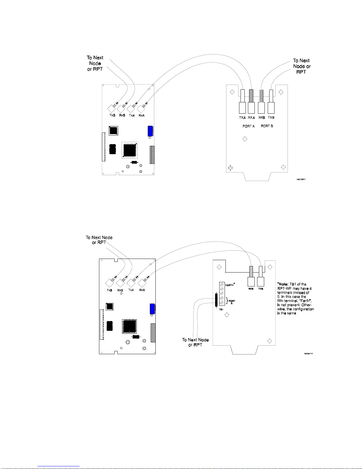
2.8 NAM-232 Connections
Figure 2.6 through Figure 2.15 depict the point-to-point connections between NAM-232s in
combination with other NAM-232s, MIBs and RPTs. When using twisted-pair wiring, polarity
need not be observed.
Installing the NAM-232
NAM-232W
NAM-232W
Figure 2.6 NAM-232W to NAM-232 W
NAM-232W RPT-W
NAM-232 50038:F 12/29/99 21
www.PDF-Zoo.com
Figure 2.7 NAM-232W to RPT-W Connections
Page 22

Installing the NAM-232
NAM-232 Connections
NAM-232W
Figure 2.8 NAM-232W to RPT-WF Connections
RPT-WF
NAM-232W
22 NAM-232 50038:F 12/29/99
www.PDF-Zoo.com
MIB-W
Figure 2.9 NAM-232W to MIB-W
Page 23

NAM-232 Connections
Installing the NAM-232
NAM-232W
MIB-WF
Figure 2.10 NAM-232W to MIB-WF Connections
NAM-232F
NAM-232 50038:F 12/29/99 23
www.PDF-Zoo.com
NAM-232F
Figure 2.11 NAM-232F to NAM-232F Connections
Page 24
Installing the NAM-232
NAM-232 Connections
NAM-232F
RPT-F
Figure 2.12 NAM-232F to RPT-F
NAM-232F
24 NAM-232 50038:F 12/29/99
www.PDF-Zoo.com
RPT-WF
Figure 2.13 NAM-232F to RPT-WF Connections
Page 25

NAM-232 Connections
Installing the NAM-232
MIB-F
NAM-232F
Figure 2.14 NAM-232F to MIB-F
MIB-WF
NAM-232 50038:F 12/29/99 25
www.PDF-Zoo.com
NAM-232F
Figure 2.15 NAM-232F to MIB-WF Connections
Page 26

Installing the NAM-232
2.9 Connecting the NAM-232 to an AFP-200
The EIA-232 serial communications interface of the AFP-200 must be wired to a NAM-232 (refer
to Table 2.4), to communicate with other nodes in a
Note: When the EIA-232 connection exceeds 50 feet (15.24 m), TPI-232 modems must be used. Refer to the Telephone/
Panel Interface (TPI-232) manual.
The use of a printer or CRT in the AFP-200 is not permitte d w he n th e NAM-23 2 is pre s ent.
AFP-200 NAM-232
Connecting the NAM-232 to an AFP-200
NOTI•FIRE•NET™
system.
TB4 terminal 1
EIA-232 Transmit
TB4 terminal 2
Reference
TB4 terminal 3
EIA-232 Receive
Table 2.4 EIA-232 Serial Connections
TB1 terminal 6
EIA-232 Receive
TB1 terminal 5
Reference
TB1 terminal 7
EIA-232 Transmit
Figure 2.16 Connecti ng the EIA-232 Interface to the AFP-200
2.10 Connecting the NAM-232 to an AFP-300/AFP-400
The EIA-232 serial communications interface of the AFP-300/AFP-400 must be wired to a
NAM-232 (refer to Table 2.5), to communicate with other nodes in a
system.
26 NAM-232 50038:F 12/29/99
www.PDF-Zoo.com
NOTI•FIRE•NET™
Page 27

Connecting an AM2020/AFP1010 Through TPI-232 Modems to a NAM-232
Note: When the EIA-232 connection exceeds 50 feet (15.24 m), TPI-232 modems must be used. Refer to the Telephone/
Panel Interface (TPI-232) manual.
AFP-300/AFP-400 NAM-232
Installing the NAM-232
Note:
Be sure to connect
the EIA-232 to TB2. TB1 is
the printer po r t a nd wi ll n ot
work.
TB2 terminal 1
EIA-232 Transmit
TB2 terminal 2
EIA-232 Receive
TB2 terminal 3
EIA-232 Reference
TB1 terminal 6
EIA-232 Receive
TB1 terminal 7
EIA-232 Transmit
TB1 terminal 5
EIA-232 Reference
Table 2.5 EIA-232 Serial Connections
Figure 2.17 Connectin g the EIA-232 Interface to t he AFP-300/AFP-400
2.11 Connecting an AM2020/AFP1010 Through TPI-232 Modems to a
NAM-232
Refer to the Telephone/Panel Interface (TPI-232) manual for information on connecting the
AM2020/AFP1010 through TPI-232 modems to a NAM-232. The use of a CRT in the AM2020/
AFP1010 is not permitted when the NAM-232 is present.
NAM-232 50038:F 12/29/99 27
www.PDF-Zoo.com
Page 28

AFP-200 Programming Requirements
Section 3 AFP-200 Programming Requirements
NOTI•FIRE•NET™ Channel Threshold Programming
When adding an AFP-200 with a NAM-232 to
be performed in the AFP-200. The AFP-200 must be programmed with network channel
thresholds, node address, LocT, and (if desired) CCBE.
NOTI•FIRE•NET™
3.1
To program
After entering the programming password, press 2 to enter network programming at the following
prompt:
The following network programming menu will display:
Press 1 to change channel thresholds and the following will display:
Channel Threshold Programming
NOTI•FIRE•NET™
NOTI•FIRE•NET™
channel thresholds, first enter programming on the AFP-200.
ENTER
1=BASIC PROGRAM
2=NETWORK PROGRAM
ENTER
1=CHANNEL THRESHOLD
2=NODE ADDRESS
3=ZONE CCBE
, certain programming must
The current high or lo w thresholds f or each channel ar e gi ven b y an 'H' or 'L' inside the parentheses.
Press 1 or 2 to toggle the threshold for channel A or channel B. Press <ENTER> when complete.
Refer to the
NAM-232 on a system is replaced, the thresholds for that panel must be reprogrammed.
NOTI•FIRE•NET™
3.2 Node Address Programming
The AFP-200 must be programmed with a node address before the NAM-232 will connect to
NOTI•FIRE•NET™
described in 3.1. Press 2 at the network programming menu to enter node address programming
and the following will display:
The current node address will be given by ‘NNN’. Enter a non-zero node address between the
specified range, and press <ENTER> when complete. If a NAM-232 on a system is replaced, the
node address for that panel must be reprogrammed.
. Enter network programing on the AFP-200 in the same manner as
ENTER
1=CH A THRESHOLD(H)
2=CH B THRESHOLD(H)
manual prior to selecting either a high or low threshold. If a
NODE ADDRESS=
TO CHANGE,ENTER #
(001-249),THEN ENTER
NNN
28 NAM-232 50038:F 12/29/99
www.PDF-Zoo.com
Page 29

CCBE Zone Programming
3.3 CCBE Zone Programming
Zones 01 through 45 on an AFP-200 may be individually programmed to activate when a zone on
another
addition to CBE activation in an AFP-200. CCBE activati on and CBE activation are "OR'ed"
together to produce local output activation.
Enter network programming on the AFP-200 in the same manner described in 3.1. Press 3 at the
network programming menu to enter CCBE programming and the following will display :
Enter a zone number (01 through 45), press <ENTER> and the following will display:
NOTI•FIRE•NET™
AFP-200 Programming Requirements
node activates. CCBE output activation may be performed in
ZONE NUMBER=01
SELECT ZONE#(01-89),
THEN ENTER:
ZXX CCBE = N***Z***
OR N***Z***
OR N***Z***
OR N***Z***
Note: Do not
use the lower
three lines of
this display.
Ignore the lower three lines of the display. Enter a network node number followed by a zone
number and press <ENTER> when complete (precede one and two digit node/zones with zeroes).
To delete network node and zone numbers, an asterisk must be entered instead of the number.
Example:
To activate zone 1 on an AFP-200 whenever
enter the following:
To delete network node and zone numbers, an asterisk must be entered instead of the number. If a
NAM-232 on a system is replaced, the CCBE for that panel must be reprogrammed.
3.4 CCBE Drill Programming
The Drill function on an AFP-200 can be programmed to activate when a zone on another
NOTI•FIRE•NET™
AFP-200 CCBE drill function, and they are programmed in the same manner as zones 0 through
45. Zones 46 through 89 on the AFP-200 cannot be activated individually through CCBE. When
the drill function is activated on an AFP-200, signals can only be silenced through a reset or signal
silence.
node activates. Zones 46 through 89 are reserved for activation of the
NOTI•FIRE•NET™
Z01 CCBE = N005Z020
OR N***Z***
OR N***Z***
OR N***Z***
node 5, zone 20 is active,
NAM-232 50038:F 12/29/99 29
www.PDF-Zoo.com
Page 30

AFP-200 Programming Requirements
Enter network programming on the AFP-200 in the same manner described in 3.1. Press 3 at the
network programming menu to enter CCBE programming and the following will display :
Enter a zone number (46 through 89) and press <ENTER>:
Additional Programming Requirements
ZONE NUMBER=01
SELECT ZONE#(01-89),
THEN ENTER:
ZXX CCBE = N***Z***
OR N***Z***
OR N***Z***
OR N***Z***
Ignore the lower three lines of the display. Enter a network node number followed by a zone
number and press <ENTER> when complete (precede one and two digit node/zones with zeroes).
Example:
To activate the drill function on an AFP-200 whenever
is active, use a local AFP-200 zone 46 through 89:
Z46 CCBE = N009Z050
OR N***Z***
OR N***Z***
OR N***Z***
To delete network node and zone numbers, an asterisk must be entered instead of the number. If a
NAM-232 on a system is replaced, the CCBE for that panel must be reprogrammed.
3.5 Additional Programming Requirements
Program the AFP-200 for LocT mode in system function programming. Do not use an AFP-200
CMX device type “blank
” as it will incorrectly appear as an MMX device type on the INA/NCS.
Note: Do not
use the lower
three lines of
this display.
NOTI•FIRE•NET™
node 9, zone 50
30 NAM-232 50038:F 12/29/99
www.PDF-Zoo.com
Page 31

AFP-300/AFP-400 (LocT)
AFP-300/AFP-400 Pr ogr ammi ng Requi remen ts
Section 4 AFP-300/AFP-400 Programming Requirements
When adding an AFP-300/AFP-400 with a NAM-232 to
programming must be performed in the AFP-300/AFP-400. The AFP-300/AFP-400 must be
programmed with network channel thresholds, node address, LocT (Local Terminal), and (if
desired) CC BE.
4.1 AFP-300/AFP-400 (LocT)
To program the AFP-300/AFP-400 for LocT, first press <ENTER>
1=PROGRAMMING 2=READ STATUS ENTRY
(ESCAPE TO ABORT)
Press 1 to enter Programming and enter the high level programming password.
ENTER PROG OR STAT PASSWORD,THEN ENTER.
(ESCAPE TO ABORT) *****
Press <ENTER>
1=BASIC PROGRAM 2=NETWORK PROGRAM
3=UTILITY (ESCAPE TO ABORT)
NOTI•FIRE•NET™
, certain
Press 1 to enter the Basic Programming Screen:
Press 7 to enter the System Function programming screen:
Ensure that LocT is selected. If not, navigate to it and change its state by using the
PREVIOUS
NOTI•FIRE•NET™
4.2
To program
AFP-400. After entering the p rogramming password, press 2 to ente r net w ork programming at the
following prompt.
0=CLR 1=AUTO 2=POINT 3=PASSWD 4=MESSAGE
5=ZONES 6=SPL FUNCT 7=SYSTEM 8=CHECK PRG
SIL INH=000 AUTO=00 0 VERIFY=30 USA TIME
TERM=N AC DLY=N LocT BL INK=Y ST=4 ACS=N
keys.
Channel Threshold Programming
NOTI•FIRE•NET™
1=BASIC PROGRAM 2=NETWORK PROGRAM
3=UTILITY (ESCAPE TO ABORT)
or
NEXT
channel thresholds, first enter programming on the AFP-300/
NAM-232 50038:F 12/29/99 31
www.PDF-Zoo.com
Page 32

AFP-300/AFP-400 Programming Requirements
The following network programming menu will display:
THRESHOLD CH.A:H, THRESHOLD CH.B:H,
NODE:000, SPECIAL ACS OFFSET:00, <ENTER>
The default Channel A threshold is set to High. To change this to Low press the + or - key or
type "L". Navigate using the
Note: Refer to the
NOTI•FIRE•NET™
4.3 Node Address Programming
The AFP-300/AFP-400 must be programmed with a node address before the NAM-232 will
connect to
NOTI•FIRE•NET™
will be highlighted. Enter a valid node address between 001 and 249.
THRESHOLD CH.A:H, THRESHOLD CH.B:H,
NODE:000, SPECI AL ACS OFFSET:00, <ENTER>
4.4 Special ACS Offset
Node Address Programmin g
key to bring the cursor to the Channel B threshold setting.
arrow
manual prior to selecting chan ne l thresholds.
. Navigate the cursor to the second line and the default Node:000
If an ACS Offset is desired, position the cursor over the default “00” and enter an off set between 1
and 30.
THRESHOLD CH.A:H, THRESHOLD CH.B:H,
NODE:000, SPECI AL ACS OFFSET:00, <ENTER>
Example: An offset of 10 would make the special annunciators appear to the network as
annunciator addresses 11 and 12.
4.5 CCBE Zone Programming
Zones 01 through 99 on an AFP-300/AFP-400 may be individually programmed to activate when a
zone on another
in addition to CBE activation in an AFP-300/AFP-400. CCBE and CBE activations are "OR'ed"
together to produce local ou tput activation. CCBE programming must be don e using the Verif ire ™
400 UP/Download Utility (Version 3.0 or higher). From the Systems Parameters screen, select the
NOTI•FIRE•NET™
Note: If these parameters were uploaded from an AFP-300/AFP-400 whose Node Address and Channel Thresholds were
programmed at the panel, the parameters would appear in their respective selection boxes.
NOTI•FIRE•NET™
tab and the screen in Figure 26 will appear.
node activ ates. CCBE outp ut acti v ation may b e perfo rmed
32 NAM-232 50038:F 12/29/99
www.PDF-Zoo.com
Page 33

CCBE Drill Programming
AFP-300/AFP-400 Pr ogr ammi ng Requi remen ts
Figure 4.1 Verifire™ Version 3.0 System Parameter Screen
CCBE Zone Programming Example
In the following example (Figure 4.2), the AFP-300/AFP-400 whose Node Address is 74 will
activat e its Zone 1 when Zone 3 of No de 5 is act i v e. Zone 2 will acti vate when Zone 15 in Node 25
activates. Zone 3 will activate when Zone 6 in Node 75 activates.
4.6 CCBE Drill Programming
The Drill function on an AFP-300/AFP-400 can be programmed to activate when a zone on another
NOTI•FIRE•NET™
switch inhibited will activate. When the drill function is activated on an AFP-300/AFP-400,
signals can be silenced only through a reset or signal silence.
In the example shown in Figure 4.3, the Drill function of the AFP-300/AFP-400 will activate when
Zone 17 in Node 150 is activated.
node activates. All outputs that are programmed as silenceable and not
Figure 4.2 CCBE Zone Programming Example
NAM-232 50038:F 12/29/99 33
www.PDF-Zoo.com
Page 34

AFP-300/AFP-400 Programming Requirements
Figure 4.3 CCBE Drill Programming Example
4.7 Additional Programming Requirements
• Do not use an AFP-300/AFP-400 CMX device type “blank”, as it will incorrectly appear as an
MMX device type on the INA/NCS.
• If a non-fire input is activated while a 300/400 is in programming mode, or just after leaving
programming mode, its activation will be reported over
• When changing an AFP-400’s panel label, the panel must be powered down to transfer this
information to the NAM-232.
Additional Programming Requirements
NOTI•FIRE•NET
.
34 NAM-232 50038:F 12/29/99
www.PDF-Zoo.com
Page 35

AM2020/AFP1010 Programming Requirements
Section 5 Programming
5.1 AM2020/AFP1010 Programming Requirements
The NAM-232 req ui res sp ecial pro gramm in g to be completed in the AM2020/AFP10 10 before the
NAM-232 and TPI-232 modems are connected. The last five characters of the AM2020/AFP1010
"All Systems Normal" message are reserved for identifying the AM2020/AFP1010 node address
on. This node address must be in the range of 001 to 249. The nod e address must be in t he form at
of "_Nxxx", where "_" is a blank space separating the node address from the rest of the custom
message and "xxx" is the node address (001 to 249) as shown below.
NOTIFIER WORLD HEADQUARTERS N001
ALL SYSTEMS NORMAL 11:00A 09/9/00
In addition, the NAM-232 must be enabled by selecting it in the Additional Parameters options in
Systems Programming. The devices with the following Software Type I.D.s will not report on
NOTI•FIRE•NET™
.
Programming
Node Address
•
SACM:
•
SEQM:
•
NONA:
shorting-type non-alarm devices.
•
NOA:
•
SUPR:
switch.
MMX Monitor Module used to monitor a security device.
MMX Monitor Module that functions identical to Type I.D. SEQM.
MMX Monitor Module or XPM-8 circuit used to monitor normally open contact,
MMX Monitor Module or XPM-8 that functions identically to Type I.D. NONA.
MMX Monitor Module or an XPM-8 circuit ded icated t o a nor mal ly op en su perv i sory
NAM-232 50038:F 12/29/99 35
www.PDF-Zoo.com
Page 36

AFP-200, AFP-300/AFP-400 Message Translations
AM2020/AFP1010 Programming Requirements
Section 6 AFP-200, AFP-300/AFP-400 Message Translations
The AFP-200/AFP-300/AFP-400 contains features which are not presently included on the INA/
NCS. Alarm, trouble, and other messages which appear on the LCD of the AFP-200 may be
modified prior to display on the INA/NCS. For example, an AFP-200 may display the following
message:
SECURITY TAMPER
PANEL DOOR OPEN
03:12A WED 11/18/00
while at the same time, the INA will display the following message:
TROUBL N148 SSYM PANEL DOOR OPEN
SECURITY TAMPER 03:12A 11/18/00 301
Note: AFP-200/AFP-300/AFP-400 devices and conditions which have no equivalent in an AM2020/AFP1010 will appear at
the INA/NCS as devices on Loop 3 (which does not physically exist).
For a complete list of message translations and specific information on AFP-200 and AFP-300/
AFP-400 addressable device types, refer to the AFP-200, AFP-300/AFP-400, INA, and NCS
manuals.
36 NAM-232 50038:F 12/29/99
www.PDF-Zoo.com
Page 37

AM2020/AFP1010 Programming Requirements
AFP-200, AFP-300/AFP-400 Message Translations
NOTES
NAM-232 50038:F 12/29/99 37
www.PDF-Zoo.com
Page 38

AFP-200, AFP-300/AFP-400 Message Translations
AM2020/AFP1010 Programming Requirements
NOTES
38 NAM-232 50038:F 12/29/99
www.PDF-Zoo.com
Page 39

Limited Warranty
®
NOTIFIER
ship for eighteen (18) months from the date of manufacture, under nor mal use and
servic e. Products a re date s tamped at time of m anufacture. The sole and exclusive
obligation of
and labor, any part which is defective in materi als or wor kmanship under nor mal use
and servic e. For products not under
the warranty is eighteen (18) mon ths from date of original purchase by
distributor unless the ins talla tion i nstr ucti ons or catalog sets fort h a shorter per iod , in
which case the shorter period shall apply. This warranty is void if the product is
altered, repaired o r serviced by anyone other th an
tributors or if there is a failure to maintain the p roducts and systems in whic h they
operate in proper and worka ble manner. In case of de fect, secure a Retu rn M ater ial
Authorization form from our c ustom er service department. Retur n pro duct, transportation prepaid, to
1653.
This writing constitutes the only warranty made by
products.
or otherwise, or that its produ cts wi ll in all c ases p rovide the pro tectio n for which they
are installed or in tended. Buyer acknowledge s that
assumes no risk for loss or damages or the cost of any inconvenience, transportation,
damage, misuse, abuse, accident or similar incident.
warrants its products to be free from defects in materials and wor kman-
®
NOTIFIER
is to repair or replace, at is option, free of charge for parts
®
NOTIFIER
manufacturing date-stamp control ,
NOTIFIER
®
or its authorized dis-
®
with respect to its
®
is not an insurer and
NOTIFIER
NOTIFIER
NOTIFIER
®
, One Fire-Lite Place, Northford, Connecticut 06472-
NOTIFIER
®
does not represent that its products will prevent any loss by fire
NOTIFIER
®
®
NOTIFIER
GIVES NO WARRANTY, EXPRESSED OR IMPLIED, OF MERC HANTABILITY, FITNESS FOR ANY PARTICULAR PURPOSE, OR OTHERWISE WHICH
EXTEND BEYOND THE DESCRIPT ION ON THE FACE HEREOF. UNDER NO CIRCUMSTANCES SHALL
NOTIFIER
®
BE LIABLE FOR ANY LOSS OF OR DAMAGE
TO PROPERTY, DIRECT, INCIDENTAL OR CONSEQUENTIAL, ARISING OUT OF
®
THE USE OF, OR INABILITY TO USE
®
NOTIFIER
SHALL NOT BE LIABLE FOR ANY PERSONAL INJURY OR DEATH
NOTIFIER
PRODUCTS. FURTHERMORE,
WHICH MAY ARISE IN THE COURSE OF, OR AS A RESULT OF, PERSONAL,
COMMERCIAL OR INDUSTRIAL USE OF ITS PRODUCTS.
This warranty replaces all previous warranties and is the only warranty made by
®
NOTIFIER
. No increase or alteration, writte n or verbal, of the obligation of this warranty is authorized.
®
NOTIFIER
is a registered trademark.
www.PDF-Zoo.com
Page 40

One Fire-Lite Place, Northford, CT 06472-1653 USA
www.PDF-Zoo.com
World Headquarters
203-484-7161 • Fax 203-484-7118
www.notifier.com
 Loading...