

Page 1
GENERAL
Wheelock’s Series MT and MT Strobe Multitone electronic
appliances offer a choice of eight (8) nationally and internationally recognized alerting sounds: Horn, Bell, March
Time Horn, Code-3 Tone, Code-3 Horn, Slow Whoop, Siren or Hi/Lo Tone. The Code-3 Horn and tone patterns
are engineered to comply with NFPA/ANSI Temporal Pattern specifications without requiring additional equipment.
With MT and MT Strobe appliances, one alarm appliance
meets most of your signaling needs. Strobe models can
be synchronized using the Wheelock SM, DSM Sync Modules or a power supply equipped with Wheelock’s patented Sync Protocol.
The MT Strobes are designed for ADA applications with
maximum performance, reliability and cost-effectiveness
while meeting or exceeding the latest requirements of
NFPA 72, ANSI 117.1, UFC and UL Standard 1971 as well
as meeting ADA requirements concerning photosensitive
epilepsy.
Each MT and MT Strobe appliance has two installer selective sound output levels: STANDARD dBA and HIGH dBA.
Non-strobe versions provide selectable voltage capability
in one unit, 12VDC or 24VDC. Strobe versions are specific
for either 12VDC or 24VDC and all models may be used
with filtered or unfiltered (full-wave-rectified) input voltages.
Separate input terminals are available, shunt wires are
provided to enable both tone and strobe to operate simultaneously from a single input.
The Series MT Multitone Strobe appliances are UL Listed
for indoor wall mount applications under Standard 1971
for Signaling Devices for the Hearing Impaired and under
Standard 464 for Audible Signaling Appliances.
March 30, 2004
Series MT
Multitone Electronic Appliances
Section: Audio/Visual Devices
E5946
(Multitone
Signals
Models)
E5946/S5391
(Multitone Strobe
Signals Models)
Series MT
DN-4855 • J-121
California
State Fire
Marshal
7125-0785:155
7135-0785:118
CS243
FEATURES
• One alarm appliance with (8) eight selective signals
to provide superior sound penetration for various
ambient and wall conditions with two field selectable
sound output levels
• Audible and strobe can operate from a single NAC
circuit with any of the (8) eight audible sounds
• Selectable input voltage on non-strobe versions.
Strobe versions are factory set for either 12 or
24VDC, with wide-Listed voltage range, filtered (DC)
and FWR
• Designed to meet or exceed ADA/NFPA/UFC/ANSI
Standards and Accessibility Guidelines
• Complies with OSHA 29, Part 1910.165
• Series MT appliances have IN and OUT wiring
terminations that accept two #12 to #18 American
Wire Gauge (AWG) wires at each terminal. Inputs
are polarized for compatibility with standard reverse
polarity type supervision
• Code-3 Horn and Tone meet ANSI/NFPA temporal
pattern for standard emergency evacuation signaling
• MT Strobe models available with 1575 and 75
candela ratings for independent or single input
activations and can be synchronized using
Wheelock’s SM or DSM sync module(s) or a power supply
with built-in Wheelock Sync Protocol
• Mounts to either 4" square or double gang boxes
(important for retrofit installations). Attractive flush or
surface mounting
• No additional trimplate required for flush mounting
NOTIFIER® is a Honeywell company.
This document is not intended to be used for installation purposes. We try to keep our product
information up-to-date and accurate. We cannot cover all specific applications or anticipate
all requirements. All specifications are subject to change without notice.
For more information, contact NOTIFIER. Phone: (203) 484-7161 FAX: (203) 484-7118
12 Clintonville Road, Northford, Connecticut 06472
DN-4855 • 03/30/04 — Page 1 of 4
Page 2
PLEASE READ THESE SPECIFICATIONS AND INSTALLATION INSTRUCTIONS CAREFULLY BEFORE USING, SPECIFYING OR
APPLYING THIS PRODUCT. FAILURE TO COMPLY WITH ANY OF THE FOLLOWING INSTRUCTIONS, CAUTIONS AND WARNINGS
COULD RESULT IN IMPROPER APPLICATION, INSTALLATION AND/OR OPERATION OF THESE PRODUCTS IN AN EMERGENCY
SITUATION, WHICH COULD RESULT IN PROPERTY DAMAGE, AND SERIOUS INJURY OR DEATH TO YOU AND/OR OTHERS.
GENERAL NOTES ON STROBES
• Strobes are designed to flash at 1 flash per second
minimum over their “Regulated Voltage Range”. Note
that NFPA-72 specifies a flash rate of 1 to 2 flashes
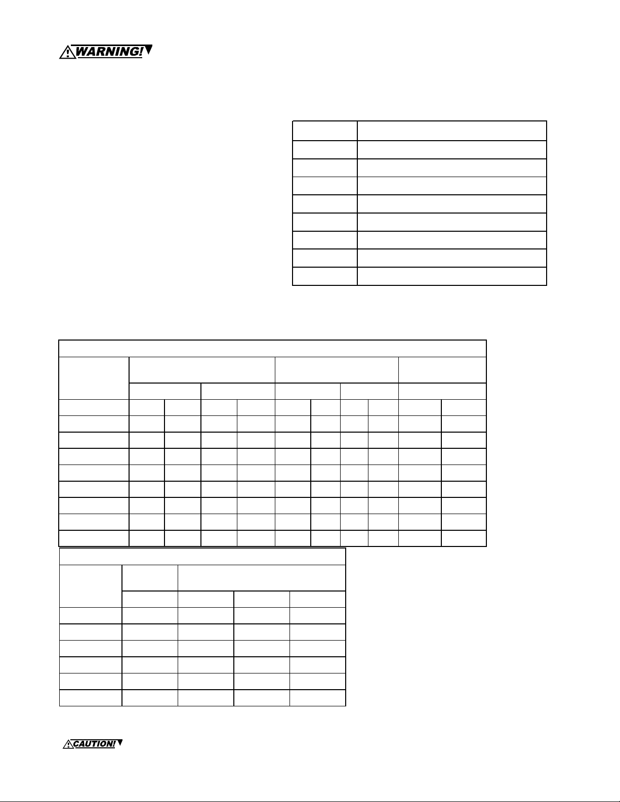
ALARM TONES
TONES PATTERN DESCRIPTION
Ho rn B ro adband Ho rn (Co ntinuo us)
per second and ADA Guidelines specifies a flash
rate of 1 to 3 flashes per second.
• All candela ratings represent minimum effective
Multitone Strobe intensity based on UL Standard
1971.
• MT Strobe models are UL Standard 1971 Listed for
indoor use with a temperature range of 32°F to 120°F
(0°C to 49°C) and maximum humidity of 93% ±2%.
B ell 1560 Hz M odulated (0.07 se. ON/Repeat)
M arch Time H orn Horn (0.25 sec. ON /0.25 sec. OFF/Repeat)
Co de-3 H orn Ho rn (A NSI S3.41 T emo pral P attern)
Co de-3 To ne 500 Hz (A NSI S3.41 Temo pral Pattern)
Sl o w Who o p 50 0-12 00 H z Swe ep (4 .0 s ec . ON /0 .5 s ec . OF F /R ep eat )
The MT-12/24 and MTWP models for outdoor use are
Listed for -31°F to 150°F (-35°C to 66°C) and maximum humidity of 95%
• MT Audible is UL Standard 464 Listed.
Siren 600-1200 H z Sweep (1.0 sec . ON/Repeat )
Hi\Lo 1000/800 Hz (0.25 sec. ON /Alternate)
• “Regulated Voltage Range” is the newest terminol-
ogy used by UL to identify the voltage range. Prior
to this change UL used the terminology “Listed
Voltage Range”.
noitroPelbiduAenotitluMrofsgnitaRtnerruCdnaABd:1elbaT
enoT
sgnitaRtnerruCnaeMegarevA
CDV42@CDV21@CDV42@CDV21@CDV42dna21@
IHDTSIHDTSIHDTSIHDTSIHDTS
nroH040.0520.0001.0020.0297809779939
lleB020.0310.0130.0010.0680858962978
nroHemiThcraM040.0520.0001.0020.0984898479939
nroH3-edoC040.0520.0001.0020.0883888379939
enoT3-edoC820.0710.0060.0510.0580848075909
poohWwolS840.0620.0001.0520.0099898579949
neriS630.0320.0280.0020.0984898578939
OL/IH120.0410.0440.0210.0681868173988
sgnitaRtnarebreveRABd
464LUreP
sgnitaRciohcenAABd
)SPMA(sgnitaRtnerruCebortS:2elbaT
LU
CDV42dna21
egnaRegatloV
CDV0.61101.512.-851.
CDV0.42460.041.-701.
CDV0.33740.411.-090.
CDV0.8--633.-
CDV0.21--971.-
CDV5.71--631.-
egarevASMR
*tnerruC
W575142-TMW5742-TMW575121-TMW5742PWTM
*tnerruCnaeMegarevA
Note: If the strobe and audible operate on the
same circuit, add the strobe current from Table
2 to the audible current from Table 1. For Peak
and Inrush current across the listed voltage
range refer to Installation Instructions.
*Average RMS Current is per UL average RMS
method and Average Mean Current is per UL
average mean method. For rated In Rush and
Peak current across the UL listed voltage range
for both filtered DC and unfiltered VRMS (FWR),
see installation instructions.
NOTES on dBA/CURRENT RATINGS TABLES ABOVE: 1) Anechoic dBA is measured on axis in a non-reflective (free field) test
room using fast meter response. For peak dBA (measured with peak meter response), add 5 dBA to typical anechoic values shown
in tables above. 2) Reverberant dBA is a minimum UL rating based on sound power measurements in a reverberant test room.
*
This setting is acceptable only for general signaling (non-fire alarm) use. Use the “high” dBA setting
with this tone or use a different tone for public mode fire alarm service.
Page 2 of 4 — DN-4855 • 03/30/04
Page 3

WIRING DIAGRAMS (for all models)
+
-
MT Signal
-
+
TO NEXT
+
APPLIANCE OR
-
EOLR
FROM
PRECEDING
FROM
APPLIANCE,
PRECEDING
SM,DSM,
APPLIANCE,
POWER SUPPLY
SM/DSM,
OR FACP
PS-12/ 24-8MP
POWER SUPPLY
or FACP
Audible signal and strobe operate in unison.
Red and black shunt-wires are supplied.
FROM
PRECEDING
APPLIANCE
OR FACP
+
--
RED
BLACK
TO NEXT
+
APPLIANCE
OR EOLR
SIGNAL
-
+
STROBE AUDIBLE
+
Audible signal and strobe operate
FROM
PRECEDING
AUDIBLE OR
FACP
FROM PRECEDING
FROM
APPLIANCE,
PRECEDING
SM/DSM,
APPLIANCE,
PS-12/ 24-8MP
POWER SUPP LY
SM,DSM,
OR FACP
POWER SUPPLY
OR FACP
+
--
++
-
independently
+
+
AUDIBLESTROBE
+
TO NEXT
AUDIBLE OR
EOLR
TO NEXT
STROBE OR
EOLR
-
Out wiring method per NFPA/NEC.
--
NOTE
: Do NOT loop wires under terminals; use In/
ORDERING INFORMATION
MODEL
NUM BER
MT-12/24-R* 12/24 - D,E,F,L,M,O,P,R X X X X X
MT-241575W-FR
MT-2475W-FR 24 75 D,E,F,L,M,O,P,R X X X X *
MTWP-2475W-FR** 24 75** (@ -°31F/-35°C M X X X X *
MT4-115-R 115VA C - D,E,J,K,N,O,R X X X X X
MT4-115-WH-V FR
INPUT
VOLTAGE
#
##
24 15 (75 on AXIS) D,E,F,L,M,O,P,R X X X X *
115VAC 15 D,E,J,K,N,O,RXXXXX
RATED
CANDELA
M OUNTING
OPTIONS***
AGENCY APPROVALS
UL M EA CSFM FM BFP
-
SYNC MODELS
SM-12/24-R 12 or 24 W X X X X X
DSM-12/24-R 12 or 24 W X X X X X
+
NOTE:
MT-12/24 Audible can be used with Wheelock’s RSSP Multi-Candela for applications requiring 15, 30, 75, 110
INPUT
VOLTAGE
AVERAGE
CURRENT (AM PS)
M OUNTING
OPTIONS***
UL M EA CSFM FM BFP
cd Wall Strobes.
**MTWP-2475W is Weatherproof and rated for 75 cd @ -31°F (-35°C). See Wheelock Data Sheet S9004 or
Installation Instruction P84150.
***For additional information on mounting please refer to Data Sheet S7000.
****SM Sync Modules are rated for 3.0 amperes at 12/24 VDC; DSM Dual Circuit Modules are rated for 3.0
amperes per circuit. Maximum number of interconnected DSM modules is twenty (20). Refer to Wheelock
Data Sheet S3000.
# Use MT-241575W when 15cd is specified. 15/75 is UL Listed for 15cd with 75cd on AXIS.
## Series WH Strobe is listed for UL Standard 1638 only. See Wheelock Instruction Sheet P83159.
Due to continous development of products offered by NOTIFIER, specifications and product availability are subject
to change without notice in accordance with NOTIFIER standard terms and conditions.
DN-4855 • 03/30/04 — Page 3 of 4
Page 4

CONTACT WHEELOCK FOR THE CURRENT “INSTALLATION INSTRUCTIONS” P82467 MT-12/24, P84155 MT w/Strobe
P84150 MTWP WEATHERPROOF “GENERAL INFORMATION” SHEET (P82380) ON THESE PRODUCTS. THESE DOCUMENTS DO UNDERGO PERIODIC CHANGES. IT IS IMPORTANT THAT YOU HAVE CURRENT INFORMATION ON THESE
PRODUCTS. THESE MATERIALS CONTAIN IMPORTANT INFORMATION THAT SHOULD BE READ PRIOR TO SPECIFYING
OR INSTALLING THESE PRODUCTS, INCLUDING:
• TOTAL CURRENT REQUIRED BY ALL APPLIANCES CONNECTED TO SYSTEM SECONDARY POWER SOURCES.
• FUSE RATINGS ON NOTIFICATION APPLIANCE CIRCUITS TO HANDLE PEAK CURRENTS FROM ALL APPLI-
ANCES ON THOSE CIRCUITS.
• COMPOSITE FLASH RATE FROM MULTIPLE STROBES WITHIN A PERSON’S FIELD OF VIEW.
• THE VOLTAGE APPLIED TO THESE PRODUCTS MUST BE WITHIN THEIR RATED INPUT VOLTAGE RANGE.
• INSTALLATION IN OFFICE AREAS AND OTHER SPECIFICATION AND INSTALLATION ISSUES.
• USE STROBES ONLY ON CIRCUITS WITH CONTINUOUSLY APPLIED OPERATING VOLTAGE. DO NOT USE STROBE
ON CODED OR INTERRUPTED CIRCUITS IN WHICH THE APPLIED VOLTAGE IS CYCLED ON AND OFF AS THE
STROBE MAY NOT FLASH.
• FAILURE TO COMPLY WITH THE INSTALLATION INSTRUCTIONS OR GENERAL INFORMATION SHEETS COULD
RESULT IN IMPROPER INSTALLATION, APPLICATION, AND/OR OPERATION OF THESE PRODUCTS IN AN EMERGENCY SITUATION,WHICH COULD RESULT IN PROPERTY DAMAGE AND SERIOUS INJURY OR DEATH TO YOU
AND/OR OTHERS.
• CONDUCTOR SIZE (AWG), LENGTH AND AMPACITY SHOULD BE TAKEN INTO CONSIDERATION PRIOR TO DESIGN AND INSTALLATION OF THESE PRODUCTS, PARTICULARLY IN RETROFIT INSTALLATIONS.
Wheelock products must be used within their published specifications and must be PROPERLY specified, applied, installed, operated, maintained and operationally tested in accordance with their installation instructions at the time of
installation and at least twice a year or more often and in accordance with local, state and federal codes, regulations and
laws. Specification, application, installation, operation, maintenance and testing must be performed by qualified personnel for proper operation in accordance with all of the latest National Fire Protection Association (NFPA), Underwriters’
Laboratories (UL), National Electrical Code (NEC), Occupational Safety and Health Administration (OSHA), local, state,
county, province, district, federal and other applicable building and fire standards, guidelines, regulations, laws and
codes including, but not limited to, all appendices and amendments and the requirements of the local authority having
jurisdiction (AHJ).
ARCHITECTS AND ENGINEERS SPECIFICATIONS
The notification appliance shall be a Wheelock Series MT audible/visual appliance or equivalent. Notification appliance
shall be electronic and use solid state components. Electromechanical alternatives are not approved. Each electronic
appliance shall provide eight (8) field selectable alarm tones. The tones shall consist of: HORN, BELL, MARCH TIME
HORN, CODE-3 HORN, CODE-3 TONE, SLOW WHOOP, SIREN and HI/LO. Tone selection shall be by durable dip
switch assembly and not clips or jumpers. The Multitone Audible appliance shall be UL Listed under Standard 464 for
Audible Signal Appliances. The audible and the strobe shall be able to operate from a single NAC circuit while
producing any of these tones. The appliance shall provide two output sound levels: STANDARD and HIGH dBA. The
HIGH dBA setting shall provide a minimum 5 dBA increase in sound output at nominal voltage. The HIGH anechoic dBA
measurement at 10 feet at the alarm HORN SETTING shall be 101 dBA minimum for MT and 92 dBA minimum for MT
Strobes, at nominal voltage. Operating voltages shall be either 12 VDC or 24 VDC using filtered power or unfiltered
power supply (full-wave-rectified). All models shall have provisions for standard reverse polarity type supervision and
IN/OUT field wiring using terminals that accept #12 to #18 AWG wiring.
Combination audible/visual appliances shall incorporate a Xenon flashtube enclosed in a rugged Lexan® lens or
equivalent with solid state circuitry. Strobe shall produce a flash rate of one (1) flash per second minimum over the
voltage range. The strobe intensity shall be rated per UL and Listed under Standard 1971 for Signaling Devices for the
Hearing Impaired for 1575 or 75 candela. The 1575 candela strobe shall be specified when 15 candela or with 75
candela intensity on-axis is required. Strobe Models shall incorporate circuitry for synchronized strobe flash and shall
be designed for compatibility with Wheelock SM and/or DSM Sync Modules or a Power Supply with Wheelock’s Sync
Protocol. The strobes shall not drift out of synchronization at any time during operation. If the module fails to operate
(i.e., contacts remain closed), the strobes shall revert to a non-synchronized default flash rate.
Strobe activation shall be via independent input or from the same input circuit as the audible.
The combination audible/visual appliances shall be installed indoors and may be surface or flush mounted. They shall
mount to standard electrical hardware requiring no additional trimplate or adapter. The aesthetic appearance shall not
have any mounting holes or screw heads visible when the installation is completed. The appliance shall be finished in
a textured red color.
The Series MT-12/24 audible appliance may be installed indoor or outdoor with the proper back box.
For Weatherproof applications where specifications require 75 cd @ -31°F (-35°C) and full temperature range
of -31°F to 150°F refer to Data Sheet S9004 and/or Installation Instructions P84150.
Page 4 of 4 — DN-4855 • 03/30/04
 Loading...