

Page 1
Page 1 of 4
1 Product Overview
The LDM Lamp Driver Modules (LDM-32, LDM-E32, and LDM-R32) are used to drive lamps or LEDs in a
custom mimic connected to an addressable fire panel.
2 Installation
WARNING: Remove all power sources to the panel before installation. Leave the
external and main power OFF until installation is complete.
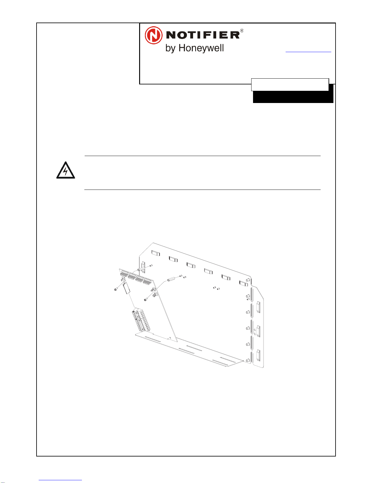
2.1 Mounting a LDM Module to a CHS Chassis
1. Screw two 3/4” stand-offs onto the mounting studs of a CHS chassis.
2. Place the module on the CHS chassis. Ensure the tab on the module slides into the slot on the
CHS chassis.
3. Secure the module with two 4-40 screws.
Figure 2-1 - Mounting the LDM to a CHS Chassis
2.2 Mounting a LDM Relay Expander
The LDM-R32 can either be mounted alongside a LDM module or expander in the CHS chassis (see
section 2.1 for CHS mounting), or stacked on top of a LDM module using the standoffs provided (see Figure
2-2.)
Make sure to connect the Relay Power Ribbon Cable between the LDM-R32 and the LDM Module, as
shown in Figure 2-3.
DOC-03-091
9 Columbia Way
Baulkham Hills, NSW 2153
PH 02-9894-1444 • FAX 02-9894-4193
www.notifier.com.au
LDM Lamp Driver
Installation Sheet - Released
26/03/2015 Rev A
Page 2
Page 2 of 4
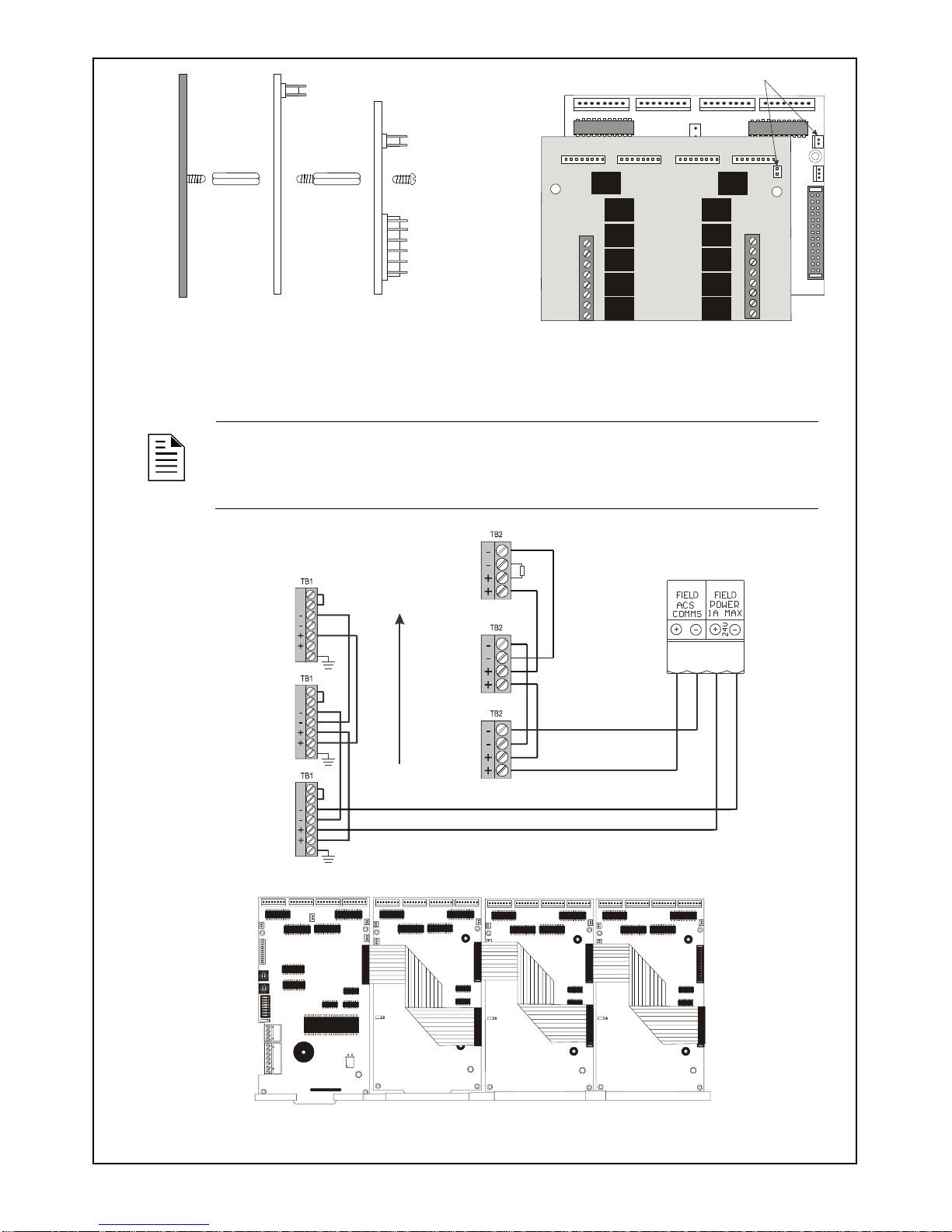
Figure 2-2 – Mounting a LDM-R32 on top of
a LDM Module
Figure 2-3 - Connecting the Relay Power
Ribbon Cable
2.3 Connections
NOTE: When cables are not run in a conduit, shielding on cables for EIA-485
connections must be grounded outside the enclosure and fire panel. See the LDM
Series Instruction Manual for more information.
Figure 2-4 – Power (TB1) and ACS Comms (TB2) connections to the CPU
Figure 2-5 - Connecting LDM-E32 expander modules with the ribbon cable
LDM-32
(or LDM-E32)
LDM-R32
Chassis
Standoff
Standoff
J10
J9
9.;>
>=D2?
J11
J5
J6
J7
J8
J2
TB4
J5
J6
J7
J8
J10
K1
K2
K3
K4
K5
K6
K27
K28
K29
K30
K31
TB1
K32
1
1
2
2
3
3
4
4
5
5
6
6
7
7
8
8
LDM-32
(or LDM-E32)
LDM-R32
Relay Power Ribbon Cable connection
IN
OUT
OUT
IN
IN
OUT
OUT
IN
IN
OUT
OUT
IN
CPU Board
120
EOL
First
LDM-32
Last
LDM-32
IN
IN
NC Supervision
Inputs
OUT
OUT
EGnd
7
6
5
4
3
2
1
IN
IN
NC Supervision
Inputs
OUT
OUT
EGnd
7
6
5
4
3
2
1
IN
IN
NC Supervision
Inputs
OUT
OUT
EGnd
7
6
5
4
3
2
1
Page 3

Page 3 of 4
Figure 2-6 - Lamp/LED Wiring for 5 V DC
Figure 2-7 - Lamp/LED Wiring for 24 V DC
NOTE: All LEDs must be in the same room as the LDM modules.
3 Configuration
3.1 Setting the Address and Operating Modes
Figure 3-1 - Rotary address & DIP switches on the LDM-32
NOTE: The available address range for the LDM-32 is 2-32 (inclusive.)
1. Set a unique address for the LDM-32 using the rotary address switches along the side of the
module.
2. Set the operating mode using the DIP switches on the LDM-32. See Table 1 for a description of the
switch functions.
3. Configure annunciator points via the panel’s keypad or through VeriFire Tools. Refer to the panel’s
Programming Manual for further information on programming the annunciator.
J11
+5
Common
J6
J5
J4
SWITCH
LAMP
POWER
J7
J8
J10
J9
Custom
Graphic
Display
System
Trouble LED
(Yellow)
Point Status LEDs:
Use RED for Alarm points
YELLOW for Trouble points, and
GREEN for Output points.
Use 680 , 1.4 W resistors
for each point if using 2 mA LEDs.
Custom
Graphic
Display
System
Trouble LED
(Yellow)
Point Status LEDs:
Use RED for Alarm points
YELLOW for Trouble points, and
GREEN for Output points.
Use 10K , 1.4 W resistors
for each point if using 2 mA LEDs.
LDM-32
Lamp Driver Address
Set in the range 02-32
Ones
Tens
DIP Switch SW3
ALARM/TROUBLE mode
ALARM ONLY mode
1
2
3
4
5
6
7
8
O
F
F
SW4
SW4
Switch set to
positionOFF
Page 4

Page 4 of 4
Switch
Bank
Switch
No.
Default
Setting
Description
SW3
1
OFF
Turn ‘ON’ when the lamp driver is used to control relays.
2
OFF
Configures the number of expander modules.
See Table for details.
3
OFF
4
OFF
Not used.
5
OFF
Turn ‘ON’ for Receive Only mode, to mirror another LDM at the
same address in a different location.
6
OFF
Turn ‘ON’ for Piezo Disable, to disable the buzzer from sounding
for any event.
7
OFF
Turn ‘ON’ for Switch Inhibit, to disable point control switches on
the annunciator.
8
OFF
Turn ‘ON’ for Flash Inhibit, to disable the flashing of LEDs for
unacknowledged events. Also disables piezo.
N.B.: Flash Inhibit must be ON when using the LDM-R32.
Table 1 – DIP Switches and Default Settings
No.
DIP Switch Settings
None
1 2 3
Table 2 - Number of Expanders
4 Supplemental Documentation
For information on...
Refer to...
Doc No.
Operating modes
LDM Series Instruction Manual
15885
Programming
AFP-3030 Australian Programming Manual
DOC-01-032
AFP-3030 New Zealand Programming Manual
DOC-01-038
XLS-3000A Australian Programming Manual
DOC-01-035
XLS-3000A New Zealand Programming Manual
DOC-01-041
Notifier NCA-2 Australian Manual
DOC-01-043
Notifier NCA-2 New Zealand Manual
DOC-01-045
Honeywell NCA-2 Australian Manual
DOC-01-044
Honeywell NCA-2 New Zealand Manual
DOC-01-046
Table 3 - Supplemental Documentation
2 3
O
F
F
1 2
O
F
F
ON
Position
OFF
Position
2 3
O
F
F
2 3
O
F
F
2 3
O
F
F
 Loading...