

Page 1
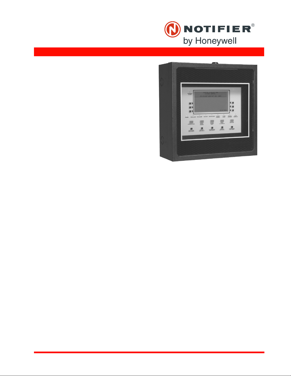
LCD-160
Liquid Crystal Display
General
The LCD-160 is a 640-character Liquid Crystal Display (LCD)
annunciator and remote control for the NOTIFIER NFS-3030/
NFS2-3030 Fire Alarm Control Panel (FACP). The LCD-160
will mimic the top portion (160 characters) of the NFS-3030/
NFS2-3030’s 640-character display. This provides the event
and preprogrammed custom messages as displayed on the
main panel. The full screen contains soft key functions, and
can display other panel information.
LCD-160 Features
• 640-character Liquid Crystal Display with backlit control.
• On-board input, output, and status indicators to support
diagnostics.
• Software upgrades and foreign-languages character sets
via serial port from a panel or other device using the
Remote Data Port (RDP) interface. Upgrades do not require
the replacement of any programmable devices.
• Rubberized keypad.
• Input for AKS-1B key switch.
• Fits in two ACS annunciator module locations.
• Display and Control Center (DCC) participation/indication.
RDP Interface
Any communication between the control panel and any RDP
device, such as the LCD-160, occurs over an RDP interface.
• RDP interface communication is supervised by the FACP
and the LCD-160.
• RDP bus can drive up to 32 RDP devices. The FACP must
be at one end of the bus; the last RDP device on the circuit
must have an enabled end-of-line resistor.
• Each LCD-160 on the bus requires a non-resettable 24
VDC power connection. The power circuit is inherently
supervised and a loss of power registers as a communication failure at the control panel.
• The LCD-160 can be powered by a regulated remote power
supply listed for fire-protective signaling use. If the 24 VDC
power comes from a non-power-limited source, it must
remain separate from the power-limited RDP bus.
Specifications
Input supply voltage (TB2): Regulated, filtered 24 VDC via
non-resettable power supply interface listed for fire-protective
signaling use. Sources can be: panels with integrated power
supplies, main power supplies (AMPS-24, etc.), auxiliary
power supplies (APS2-6R, etc.); or a compatible accessories
output. If RDP devices are to be powered by separate power
supplies, a common reference connection must be established.
Data communications port (TB1): Power-limited RDP interface.
DN-6940:B1 • D-115
Annunciator Control Systems
Current draw: Standby current: 0.300 A with backlight on,
0.075 A with backlight off. Alarm current: 0.325 A with backlight on, all LEDs active.
RDP BUS WIRING SPECIFICATIONS
Wiring distance: 4000 feet (1219.2 m) at 18 AWG (0.78 mm²)
between the panel and the last device on the RDP bus (subject to system’s power restrictions).
Wiring size: 18 to 12 AWG (0.78 to 3.1 mm²) twisted-pair
cable, with characteristic impedance of 120 ohms ± 20%.
Wire resistance: Limit total wire resistance to 100 ohms on
the RDP bus, and 10 ohms on the RDP device power circuit.
Unloaded resistance between RDP connectors must be
greater than 1K ohm. A remote power supply is required if total
power wiring resistance exceeds 10 ohms.
NOTE: 1) DO NOT RUN CABLE adjacent to, or in the same conduit as: 120 VAC service; “noisy” electrical circuits that are powering mechanical bells or horns; audio circuits above 25 Vrms; motor
control circuits; SCR power circuits; or non-power-limited circuits.
2) Refer to LCD-160 Manual, document no. 51850, if RDP devices
are to be mounted in SEPARATE CABINETS or powered by
REMOTE POWER SUPPLIES.
PHYSICAL SPECIFICATIONS
Temperature/humidity range: This system meets NFPA
requirements for operation at 0 – 49°C/32 – 120°F and at a
relative humidity 93% ± 2% RH (noncondensing) at 32°C ±
2°C (90°F ± 3°F). However, the useful life of the system's
standby batteries and the electronic components may be
adversely affected by extreme temperature ranges and humidity. Therefore, it is recommended that this system and its
peripherals be installed in an environment with a normal room
temperature of 15 – 27°C/60 – 80°F.
Shipping weight: 2.50 lb. (1.134 kg)
DN-6940:B1 • 8/31/2011 — Page 1 of 4
Page 2
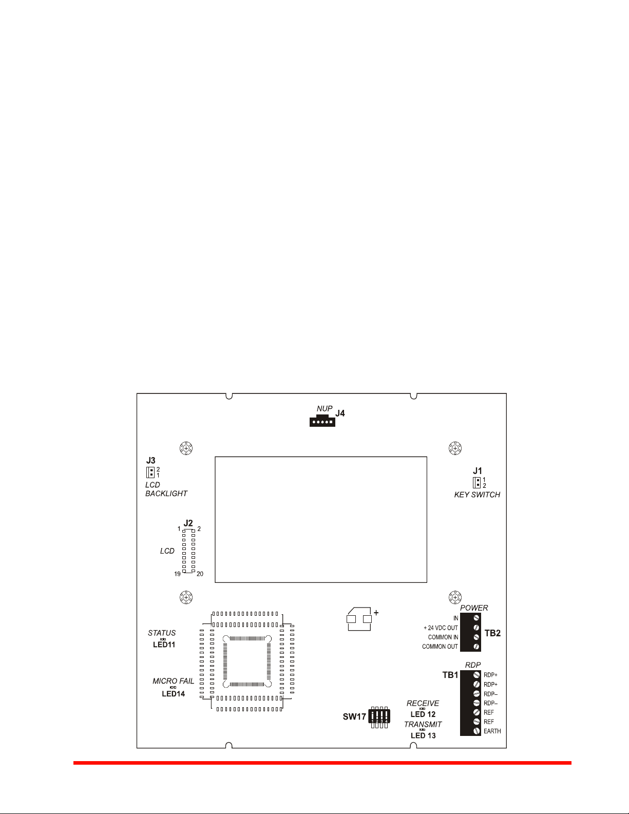
LCD-160 Interface and Indicators
6940bord.wmf
LCD-160
The liquid crystal display is 40 characters wide and 16 lines
deep, and displays all programming screens and other information. The keypad is functional only when an entry is
requested by the system. Enter or change fields and issue
commands on the display by using the two types of keys on
the keypad: fixed function and soft keys.
Fixed function keys are the ten keys labeled on the front of
the LCD-160, operating at all times on all screens unless otherwise noted. With both an active command center and DCC
enabled at the panel, Acknowledge, Signal Silence, System
Reset, and Drill require permission before they can be processed.
Acknowledge: Press to respond to any event or trouble signal. If enabled, silences the LCD-160 piezo sounder. Sends an
acknowledge message to the panel.
Signal Silence: Press to send a system silence command to
the panel, with the particular silencing action information
stored at the FACP. Verification screen appears on networked
displays.
System Reset: Press to send a system reset command to the
panel, with the particular reset action information stored at the
FACP. Verification screen appears on networked displays.
Drill: Press (hold for two seconds) to activate all silenceable
fire output circuits.
Lamp Test: Press to test the LED indicators and the piezo, or
display firmware version numbers.
Fire Alarm: Scroll/display a list of associated events.
Security: Scroll/display a list of associated events.
Supervisory: Scroll/display a list of associated events.
Trouble: Scroll/display a list of associated events.
Other Event: Scroll between prealarm and disabled events.
For complete information on key functions and effects on different panels, refer to the LCD-160 Manual and panel manuals.
Soft keys are the six keys to the right and left of the display.
Use them to select commands that appear on the display for
each different screen. Refer to the screens in the LCD-160
Manual for descriptions of the applicable soft keys.
STATUS LED INDICATORS
Power (green) illuminates when AC power is within normal
operating limits.
Fire Alarm (red) illuminates when at least one fire alarm event
exists. It will flash if any of these events are unacknowledged.
Pre-Alarm (red) illuminates when at least one pre-alarm event
exists. It will flash if any of these events are unacknowledged.
Security (blue) illuminates when at least one security event
exists. It will flash if any of these events are unacknowledged.
Supervisory (yellow) illuminates when at least one supervi-
sory event exists. It will flash if any of these events are unacknowledged.
System Trouble (yellow) illuminates when at least one trou-
ble event exists. It will flash if any of these events are unacknowledged.
Other Event (yellow) (future release).
Page 2 of 4 — DN-6940:B1 • 8/31/2011
Page 3

Signals Silenced (yellow) illuminates if notification appli-
RDP Bus Wire Runs
Sample Screen:
Point Event Display
ances have been silenced. It flashes if some, but not all, of the
NACs have been silenced.
Point Disabled (yellow) illuminates when at least one device
has been disabled. It will flash until all disabled points have
been acknowledged.
Controls Active (green) illuminates when the LCD-160
assumes control of the node as a primary display.
DIAGNOSTIC LED INDICATORS
Status, LED11 (green), blinks when the LCD-160 is on. Visi-
ble to the installer/troubleshooter only.
Receive, LED12 (green), blinks when data is received from
the panel. Visible to the installer/troubleshooter only.
Transmit, LED13 (green), blinks when data is transmitted to
the panel. Visible to the installer/troubleshooter only.
Microfail, LED14 (yellow), illuminates if the microcontroller
fails. Visible to the installer/troubleshooter only.
Event Handling and the
Display and Control Center
UL and ULC require that when multiple command and control
centers are installed, only one operator at any location can be
in control at any given time for functions such as acknowledge,
silence, and reset. This is called the Display and Control Center (DCC). DCC operation provides a mechanism to pass net-
work control to alternate network control centers. This protocol
allows for a “request for control” from another networked
panel, which will be accepted or rejected from the current
DCC. A 15-second time-out allowance provides for an automatic passing of control in the event there is no response from
the original DCC. If the NFS-3030/NFS2-3030 panel associated with an LCD-160 has been programmed to participate in
DCC, all remote displays with Local Control ON will automatically participate.
Agency Listings and Approvals
These listings and approvals apply to the LCD-160. In some
cases, certain modules or applications may not be listed by
certain approval agencies, or listing may be in process. Consult factory for latest listing status.
• UL: S635
• ULC: S635
• MEA: 8-04-E (annunciator only)
• FDNY: COA#6065 (with NFS2-3030)
• CSFM: 7120-0028:0227, 7165-0028:0224
• FM Approved
DN-6940:B1 • 8/31/2011 — Page 3 of 4
Page 4

Made in the U.S. A.
Product Line Information
LCD-160: 640-character Liquid Crystal Display annunciator.
Backboxes
The following backboxes can be surface- or semi-flushmounted to provide an enclosure for remote mounting. Use
with 1/2" (1.27 cm) conduit in the provided knockouts.
ABS-2D (black) and ABS-2DR (red): Surface- or semi-flush
enclosure for remote mounting. Mounts an LCD-160 directly to
the enclosure’s hinged dress plate. The ABS-2D and ABS2DR do NOT support the installation of the AKS-1B keyswitch. Not for use in Canadian applications. Optional trim ring
TR-ABS2D for semi-flush mounting. Dimensions, box: 12.0"
(30.480 cm) H x 12.0" (30.480 cm) W x 3.797" (9.644 cm) D
(NOTE: The black ABS-2D is slightly deeper). Dimensions,
door: 12.0" (30.480 cm) H x 12.0" (30.480 cm) W x 1.250"
(3.175 cm) D.
ABS-4D (black) and ABS-4DR (red): Surface- or semi-flushenclosure for remote mounting. Mounts an LCD-160 and two
annunciators directly to the enclosure’s hinged dress plate.
The ABS-4D and ABS-4DR do NOT support the installation of
the AKS-1B key-switch. Dimensions, box: 11.97" (30.40 cm)
H x 19.87" (50.47 cm) W x 3.5" (8.89 cm) D. Dimensions,
door: 11.97" (30.40 cm) H x 19.87" (50.47 cm) W x 1.250"
(3.175 cm) D.
ABF-2B: Black flush enclosure for remote mounting. Mounts
an LCD-160 directly to the enclosure’s dress plate. Not for use
in Canadian applications. Includes a painted black metal trim
plate [11" (27.94 cm) high x 10.625" (26.99 cm) wide] and
adhesive-backed annunciator label. 9.938" (25.24 cm) high x
9.188" (23.34 cm) wide x 3.75" (9.525 cm) deep.
ABF-2DB: Black flush enclosure for remote mounting. Mounts
an LCD-160 directly to the enclosure’s dress plate. Does not
support the installation of AKS-1B. Box dimensions: 9.938"
(25.24 cm) high x 9.188" (23.24 cm) wide x 3.75" (9.525 cm)
deep.Door dimensions: 11" (29.94 cm) high x 10.375" (26.35
cm) wide x 0.75" (1.9 cm) deep.
ABF-4B: Black flush enclosure for remote mounting of one
LCD-160 and two annunciator modules directly to the enclosure’s dress plate. Knockouts are provided for use with 1/2"
(1.27 cm) conduit. Includes a painted black metal trim plate
[11" (27.94 cm) high x 19.375" (49.21 cm) wide] and an annunciator label. 9.938" (25.24 cm) high x 17.75" (45.09 cm) wide x
2.5" (6.35 cm) deep.
CAB-4 Series cabinets: Surface- or semi-flush-mounted, in
sizes to accommodate one to four rows of equipment plus batteries (up to two 26 AH batteries). Four sizes are available.
Doors are ordered separately, and feature reversible hinges to
mount doors on the left or right side. Doors also open a full
180°. Keylocks are included. For dimensions and further information, see datasheet DN-6857.
ACCESSORIES
DP-DISP: Dress Panel Display for cabinet mounting of an
LCD-160. LCD-160 mounts directly to the dress panel, which
hinge-mounts to the top tier of a CAB-4 Series backbox.
ADP-4B: Annunciator Dress Panel-4B (black) for cabinet
mounting of an LCD-160. LCD-160 mounts directly to the
dress panel, which hinge-mounts to the tier of a CAB-4 Series
backbox.
TR-ABS2D: Optional trim ring for semi-flush mounting ABS2D(R).
VP-2B: Vented Dress Panel for use with the ADP-4B dress
panel installed in the top tier of a NOTIFIER cabinet. It covers
the gap between the dress panel and top of the cabinet.
AKS-1B: Annunciator Key Switch provides access security for
the control switches on the LCD-160. Key-switch kit includes
key, hardware, and an annunciator label.
NOTIFIER® is a registered trademark of Honeywell International Inc.
©2011 by Honeywell International Inc. All rights reserved. Unauthorized use
of this document is strictly prohibited.
This document is not intended to be used for installation purposes.
We try to keep our product information up-to-date and accurate.
We cannot cover all specific applications or anticipate all requirements.
All specifications are subject to change without notice.
For more information, contact Notifier. Phone: (203) 484-7161, FAX: (203) 484-7118.
www.notifier.com
Page 4 of 4 — DN-6940:B1 • 8/31/2011
 Loading...