

Page 1

Intelligent Network Annunciator
www.PDF-Zoo.com
INA
Document 15092
05/30/01 Rev:
P/N 15092:I 0 1 - 1 4 9
I
Page 2

Fire Alarm System Limitations
While a fire alarm system may lower insurance
rates, it is not a substitute for fire insurance!
An automatic fire alarm system–typically made up of smoke
detectors, heat detectors, manual pull stations, audible warning devices, and a fire alarm control with remote notification
capability–can provide early warning of a developing fire.
Such a system, however, does not assure protection against
property damage or loss of life resulting from a fire.
The Manufacturer recommends that smoke and/or heat detectors be located throughout a protected premise following the
recommendations of the current edition of the National Fire
Protection Association Standard 72 (NFPA 72),
manufacturer's recommendations, State and local codes, and
the recommendations contained in the Guide for Proper Use
of System Smoke Detectors, which is made available at no
charge to all installing dealers. A study by the Federal Emergency Management Agency (an agency of the United States
government) indicated that smoke detectors may not go off in
as many as 35% of all fires. While fire alarm systems are designed to provide early warning against fire, they do not guarantee warning or protection against fire. A fire alarm system
may not provide timely or adequate warning, or simply may not
function, for a variety of reasons:
Smoke detectors may not sense fire where smoke cannot
reach the detectors such as in chimneys, in or behind walls, on
roofs, or on the other side of closed doors. Smoke detectors
also may not sense a fire on another level or floor of a building. A second-floor detector, for example, may not sense a
first-floor or basement fire.
Particles of combustion or "smoke" from a developing fire
may not reach the sensing chambers of smoke detectors because:
• Barriers such as closed or partially closed doors, walls, or
chimneys may inhibit particle or smoke flow.
• Smoke particles may become "cold," stratify, and not reach
the ceiling or upper walls where detectors are located.
• Smoke particles may be blown away from detectors by air
outlets.
• Smoke detectors may be drawn into air returns before
reaching the detector.
The amount of "smoke" present may be insufficient to alarm
smoke detectors. Smoke detectors are designed to alarm at
various levels of smoke density. If such density levels are not
created by a developing fire at the location of detectors, the
detectors will not go into alarm.
Smoke detectors, even when working properly, have sensing
limitations. Detectors that have photoelectronic sensing
chambers tend to detect smoldering fires better than flaming
fires, which have little visible smoke. Detectors that have ionizing-type sensing chambers tend to detect fast-flaming fires
better than smoldering fires. Because fires develop in different ways and are often unpredictable in their growth, neither
type of detector is necessarily best and a given type of detector may not provide adequate warning of a fire.
Smoke detectors cannot be expected to provide adequate
warning of fires caused by arson, children playing with
matches (especially in bedrooms), smoking in bed, and violent
explosions (caused by escaping gas, improper storage of
flammable materials, etc.).
Heat detectors do not sense particles of combustion and
alarm only when heat on their sensors increases at a predetermined rate or reaches a predetermined level. Rate-of-rise
heat detectors may be subject to reduced sensitivity over time.
For this reason, the rate-of-rise feature of each detector
should be tested at least once per year by a qualified fire protection specialist.
Heat detectors are designed to protect
property, not life.
IMPORTANT!
Smoke detectors must be installed in the
same room as the control panel and in rooms used by the system for the connection of alarm transmission wiring, communications, signaling, and/or power.
cated, a developing fire may damage the alarm system, crippling its ability to report a fire.
Audible warning devices such as bells may not alert people
if these devices are located on the other side of closed or
partly open doors or are located on another floor of a building.
Any warning device may fail to alert people with a disability or
those who have recently consumed drugs, alcohol or medication. Please note that:
• Strobes can, under certain circumstances, cause seizures
in people with conditions such as epilepsy.
• Studies have shown that certain people, even when they
hear a fire alarm signal, do not respond or comprehend the
meaning of the signal. It is the property owner's responsibility to conduct fire drills and other training exercise to make
people aware of fire alarm signals and instruct them on the
proper reaction to alarm signals.
• In rare instances, the sounding of a warning device can
cause temporary or permanent hearing loss.
A fire alarm system will not operate without any electrical
power. If AC power fails, the system will operate from standby
batteries only for a specified time and only if the batteries
have been properly maintained and replaced regularly.
Equipment used in the system may not be technically compatible with the control. It is essential to use only equipment
listed for service with your control panel.
Telephone lines needed to transmit alarm signals from a
premise to a central monitoring station may be out of service
or temporarily disabled. For added protection against telephone line failure, backup radio transmission systems are recommended.
The most common cause of fire alarm malfunction is inadequate maintenance. To keep the entire fire alarm system in
excellent working order, ongoing maintenance is required per
the manufacturer's recommendations, and UL and NFPA standards. At a minimum, the requirements of Chapter 7 of NFPA
72 shall be followed. Environments with large amounts of
dust, dirt or high air velocity require more frequent maintenance. A maintenance agreement should be arranged
through the local manufacturer's representative. Maintenance
should be scheduled monthly or as required by National and/
or local fire codes and should be performed by authorized professional fire alarm installers only. Adequate written records
of all inspections should be kept.
If detectors are not so lo-
Precau-Lg.p65 01/18/2000
www.PDF-Zoo.com
Page 3

Installation Precautions
Adherence to the following will aid in problem-free
installation with long-term reliability:
WARNING -
nected to the fire alarm control panel.
of power before servicing. Control unit and associated equipment may be damaged by removing and/or inserting cards,
modules, or interconnecting cables while the unit is energized.
Do not attempt to install, service, or operate this unit until this
manual is read and understood.
CAUTION -
Changes.
must be tested in accordance with NFPA 72 Chapter 7 after
any programming operation or change in site-specific software. Reacceptance testing is required after any change, addition or deletion of system components, or after any modification, repair or adjustment to system hardware or wiring.
All components, circuits, system operations, or software functions known to be affected by a change must be 100% tested.
In addition, to ensure that other operations are not inadvertently affected, at least 10% of initiating devices that are not
directly affected by the change, up to a maximum of 50 devices, must also be tested and proper system operation verified.
This system meets NFPA requirements for operation at
0-49° C/32-120° F
condensing) at 30° C/86° F. However, the useful life of the
system's standby batteries and the electronic components
may be adversely affected by extreme temperature ranges
and humidity. Therefore, it is recommended that this system
and all peripherals be installed in an environment with a nominal room temperature of 15-27° C/60-80° F.
Verify that wire sizes are adequate for all initiating and
indicating device loops. Most devices cannot tolerate more
than a 10% I.R. drop from the specified device voltage.
Several different sources of power can be con-
Disconnect all sources
System Reacceptance Test after Software
To ensure proper system operation, this product
and at a relative humidity of 85% RH (non-
Like all solid state electronic devices, this system may
operate erratically or can be damaged when subjected to lightning-induced transients. Although no system is completely
immune from lightning transients and interferences, proper
grounding will reduce susceptibility.
Overhead or outside
aerial wiring is not recommended, due to an increased susceptibility to nearby lightning strikes.
cal Services Department if any problems are anticipated or
encountered.
Disconnect AC power and batteries prior to removing or inserting circuit boards. Failure to do so can damage circuits.
Remove all electronic assemblies prior to any drilling, filing,
reaming, or punching of the enclosure. When possible, make
all cable entries from the sides or rear. Before making modifications, verify that they will not interfere with battery, transformer, and printed circuit board location.
Do not tighten screw terminals more than 9 in-lbs.
Over-tightening may damage threads, resulting in reduced
terminal contact pressure and difficulty with screw terminal
removal.
Though designed to last many years, system components
can fail at any time. This system contains static-sensitive
components. Always ground yourself with a proper wrist strap
before handling any circuits so that static charges are removed from the body. Use static-suppressive packaging
to protect electronic assemblies removed from the unit.
Follow the instructions in the installation, operating, and
programming manuals. These instructions must be followed
to avoid damage to the control panel and associated
equipment. FACP operation and reliability depend upon
proper installation by authorized personnel.
Consult with the Techni-
FCC Warning
WARNING: This equipment generates, uses, and can
radiate radio frequency energy and if not installed and
used in accordance with the instruction manual, may
cause interference to radio communications. It has
been tested and found to comply with the limits for class
A computing device pursuant to Subpart B of Part 15 of
FCC Rules, which is designed to provide reasonable
protection against such interference when operated in a
commercial environment. Operation of this equipment in
a residential area is likely to cause interference, in which
case the user will be required to correct the interference
at his own expense.
www.PDF-Zoo.com
Canadian Requirements
This digital apparatus does not exceed the Class A
limits for radiation noise emissions from digital
apparatus set out in the Radio Interference Regulations
of the Canadian Department of Communications.
Le present appareil numerique n'emet pas de bruits
radioelectriques depassant les limites applicables aux
appareils numeriques de la classe A prescrites dans le
Reglement sur le brouillage radioelectrique edicte par le
ministere des Communications du Canada.
Precau-Lg.p65 01/18/2000
Page 4

Table of Contents
C
HAPTER ONE INSTALLATION .............................................................. 8
SECTION 1 INA FEATURES ............................................................................................................................................... 8
1.1 PRODUCT FEATURES ............................................................................................................................................................ 8
1.2 RELATED DOCUMENTATION .................................................................................................................................................. 9
1.3 DIAGNOSTIC I NDICATORS AND CONTROLS ............................................................................................................................ 10
SECTION 2 INA MOUNTING CONNECTIONS ...............................................................................................................11
2.1 INA CONTROL/DISPLAY PANEL ......................................................................................................................................... 11
2. 2 INA MOUNTING .............................................................................................................................................................. 11
2.2.1 ABS-4D Cabinet .......................................................................................................................................................... 11
2.2.2 ABF-4 Cabinet ............................................................................................................................................................ 12
Annunciator Key Switch (AKS-1) or Shunt Plug................................................................................................................. 13
2.2.3 CAB-3 Cabinets ........................................................................................................................................................... 14
2.3 EIA-232 Communications Connections ......................................................................................................................... 14
Installing an Ancillary Device on the EIA-232 Communications Circuit .............................................................................. 14
2.4 THE CRT TERMINAL ........................................................................................................................................................ 18
2.5 Printers .......................................................................................................................................................................... 18
2.6 EIA-485 ACS Annunciator Interface ............................................................................................................................. 21
2.7 Powering the INA .......................................................................................................................................................... 23
2.7.1 The Main Power Supply (MPS-24A or MPS-24AE) .................................................................................................... 24
2.7.2 THE M AIN POWER SUPPLY (MPS-24B OR MPS-24BE) ................................................................................................... 25
2.7.3 REMOTE SUPPLY ............................................................................................................................................................ 26
2.8 APPLYING/REMOVING POWER TO THE INA ......................................................................................................................... 26
CHAPTER TWO OPERATION ............................................................. 27
ABOUT NVRAMS ................................................................................................................................................................. 28
ABOUT THIS CHAPTER ............................................................................................................................................................. 28
ABOUT THE PASSWORDS .......................................................................................................................................................... 28
ABOUT THE SOFTWARE ............................................................................................................................................................ 28
ABOUT GROUPS AND LINKING .................................................................................................................................................. 29
ABOUT ANNUNCIATOR OPERATION WITH THE INA ..................................................................................................................... 30
ABOUT THE DISPLAY TIME ...................................................................................................................................................... 30
ABOUT THE BACKSPACE KEY ................................................................................................................................................... 31
ABOUT THE PRINT TIME ...........................................................................................................................................................31
ABOUT PRIORITIES .................................................................................................................................................................. 31
SECTION 1 THE KEYPAD AND LIQUID CRYSTAL DISPLAY (LCD) ........................................................................... 32
1.1 NORMAL OPERATION ........................................................................................................................................................ 32
1.2 READ STATUS ................................................................................................................................................................... 33
SECTION 2 FIRE ALARMS .............................................................................................................................................. 39
2.1 Acknowledging a Fire Alarm ......................................................................................................................................... 47
SECTION 3 SECURITY ALARM, SUPERVISORY AND TROUBLE SIGNALS............................................................. 48
3.1 SECURITY A LARM, SUPERVISORY, AND TROUBLE S IGNALS FROM AM2020/AFP1010, AFP-200 AND AFP-300/400 SLC LOOP
DEVICES .......................................................................................................................................................................... 48
3.2 TROUBLE ......................................................................................................................................................................... 49
3.2.1 Trouble With AM2020/AFP1010 Disabled Zones ...................................................................................................... 49
3.2.2 Trouble With AM2020/AFP1010, AFP-200 and AFP-300/400 Equipment ................................................................... 50
3.2.3 Trouble With AM2020/AFP1010 Annunciators ......................................................................................................... 50
3.2.4 Trouble With INA and NCS Equipment ...................................................................................................................... 51
3.2.5 Trouble With Network Communications ..................................................................................................................... 51
3.3 BLOCK ACKNOWLEDGE .................................................................................................................................................... 52
3.4 ACKNOWLEDGING TROUBLES IN RECEIVING UNIT MODE ..................................................................................................... 53
4
www.PDF-Zoo.com
INA 15092:I 05/30/01
Page 5

3.5 DISPLAYING CURRENT ALARMS AND TROUBLES .................................................................................................................. 53
SECTION 4 REMOTE PERIPHERALS ............................................................................................................................ 54
4.1 PRINT FUNCTIONS ............................................................................................................................................................. 54
SECTION 5 THE SPLIT HISTORY BUFFER ................................................................................................................... 55
CHAPTER THREE PROGRAMMING .................................................... 56
SECTION 1 INA PROGRAMMING .................................................................................................................................. 57
1.1 INTRODUCTION ................................................................................................................................................................. 57
1.1.2 PROGRAMMING ANNUNCIATOR POINTS ............................................................................................................................. 58
1.2 THE INITIAL PROGRAMMING OUTLINE ................................................................................................................................58
SECTION 2 THE MAIN PROGRAMMING MENU ........................................................................................................... 59
2. 1 PARTIAL SYSTEM PROGRAMMING ....................................................................................................................................... 61
2. 2 PARTIAL POINT PROGRAMMING ......................................................................................................................................... 65
2.2.1 INA ACS PROGRAMMING EXAMPLE ................................................................................................................................67
2.3 FULL POINT PROGRAMMING .............................................................................................................................................. 68
2. 4 POINT R EMOVAL .............................................................................................................................................................. 68
2. 5 PASSWORD ....................................................................................................................................................................... 68
2.6 MESSAGE ........................................................................................................................................................................ 69
SECTION 3 THE INA ALTER STATUS MENU ................................................................................................................. 69
APPENDIX A POWER SUPPLY CALCULATIONS ................................... 72
APPENDIX B SOFTWARE TYPE IDS ................................................... 74
APPENDIX C PROGRAMMING SHEET ................................................ 76
INA 15092:I 05/30/01
www.PDF-Zoo.com
5
Page 6

Notes...
6
www.PDF-Zoo.com
INA 15092:I 05/30/01
Page 7

INA
INTELLIGENT NETWORK ANNUNCIATOR
INA 15092:I 05/30/01
www.PDF-Zoo.com
CHAPTER ONE
INSTALLATION
7
Page 8

INTELLIGENT NETWORK ANNUNCIATOR
CHAPTER ONE INSTALLATION
SECTION 1 INA FEATURES
1.1 PRODUCT F EATURES
The following features are available with the INA:
Optically isolated EIA-232 printer interface
Optically isolated EIA-232 CRT interface
Optically isolated EIA-485 ACS annunciator interface
Status LEDs indicate:
- Power
- Fire Alarm
- Security Alarm
- Supervisory
- System Trouble
- Signals Silenced
- CPU Failure
Piezo electric sounder
Alphanumeric keypad with tactile and audible feedback
40-character, 2-line Liquid Crystal Display (LCD) with backlight
Accepts NOTIFIRENET Media Interface Boards (MIB)
Nonvolatile Real-Time Clock (RTC)
Requires 24 VDC only
Optional power supply supervision (in-cabinet supply)
Acknowledge (Network Wide and Local to INA)
Silence (Network Wide)
Reset (Network Wide)
Lam p Test (Local to INA)
Read Status (Network Wide)--AM2020, AFP1010, AFP-300, AFP-400 systems only
Alter Status (Network Wide)--AM2020, AFP1010, AFP-300, AFP-400 systems only
Split History Buffer (20% alarms, 80% events)
- 500 Events
8
www.PDF-Zoo.com
INA 15092:I 05/30/01
Page 9

1.2 RELATED DOCUMENTATION
To obtain a complete understanding of specific features in the INA or to become familiar with functions in general, make use
of the documentation noted in Table 1.2-1. The NOTIFIER document (DOC-NOT) chart provides the current document
revision. A copy of this document is included with every Notifier shipment.
TITLE NUMBER TITLE NUMBER
AM2020/AFP1010 15088 ANNUNCIATOR CONTROL SYSTEM 15842
FIRE ALARM CONTROL PANEL
LIQUID C RYSTAL D ISPLAY (LCD-80) 15037 LAMP D RIVER MODULES (LDM) 15885
NETWORK CONTROL STATION (NCS) 51095 VOICE A LARM MULTIPLEX 15889
INTELLIGENT NETWORK A NNUNCIATOR (INA) 15092 THE XP SERIES TRANSPONDER SYSTEM 15888
UNIVERSAL Z ONE CODER INSTALLATION 15216 NETWORK A DAPTOR MODULE (NAM-232) 50038
PRODUCT I NSTALLATION DOCUMENT (CCM-1) 15328 THE UDACT UNIVERSAL D IGITAL 50050
PRODUCT I NSTALLATION DOCUMENT (MPS-TR) 15331 FCPS-24/FCPS-24E FIELD 50059
AM2020/AFP1010 OPERATOR INSTRUCTIONS 15337 VIDEO G RAPHICS ANNUNCIATOR S YSTEM 50251
NOTIFIER DEVICE C OMPATIBILITY D OCUMENT 15378 MEDIA INTERFACE BOARD (MIB) 50255
ANALOG F IRE PANEL (AFP-200) 15511 REPEATER (RPT) 50256
CANADIAN REQUIREMENTS FOR THE 15631 NOTI-FIRE-NET
NETWORK INTERFACE B OARD (NIB-96) 15666 TELEPHONE/PANEL I NTERFACE (TPI-232) 50372
ANALOG FIRE P ANEL (AFP-300/AFP-400) 50253/50259/ FZM INSTALLATION INSTRUCTIONS 1172-02
ACT-2 AUDIO COUPLING T RANSFORMER 51118 CHG-120 BATTERY CHARGER 50641
(UZC-256)
ALARM COMMUNICATOR/TRANSMITTER
CHARGER/POWER SUPPLY I NSTALLATION ,
OPERATION AND APPLICATION M ANUAL
(VGAS) INSTALLATION MANUAL
TM
AM2020/AFP1010
SMOKE CONTROL M ANUAL 15712 AUTOMATIC F IRE A LARM 50705
WARDEN STATION SERIES
PRODUCT INSTALLATION D RAWING
50260
50257
APS-6R AUXILIARY P OWER SUPPLY 50702 XP5 SERIES T RANSPONDERS 50786
INA 15092:I 05/30/01
www.PDF-Zoo.com
RM-1 REMOTE MICROPHONE 51138 VEC 25/50 VOICE EVACUATION 50686
CONTROL P ANEL
NBG-12LX PULL STATION 51093
Table 1.2-1 Related Documentation
9
Page 10

1.3 DIAGNOSTIC INDICATORS AND CONTROLS
The INA has diagnostic LED indicators (refer to Figure 1.31) which aid in troubleshooting and assist the installer in
connecting the system. Refer to Table 1.3-1 for a list of diagnostic LED indicators and their descriptions. The function
keys of the INA, as displayed in Figure 1.3-1, are detailed in Chapter Two of this document.
DEL
rotacidnIroloCnoitpircseD
REWOPneerG.nosirewopelihwsetanimullirotacidniehT
MRALAERIFdeR.langismralaerifagnirudsetanimullI
YTIRUCES
MRALA
YROSIVREPUSwolleY
METSYS
ELBUORT
SLANGIS
DECNELIS
ERULIAFUPCwolleY
wolleY.langismralaytirucesagnirudsetanimullI
wolleY
wolleY
Table 1.3-1 Identifying LED Indicators
.e.i(langisyrosivrepusagnirudsetanimullI
erif,erusserpwol,lamronffoevlavrelknirps
).cte,ruotsdraug,gninnurpmup
rolangiselbuortagnirudsetanimullI
.langisssecorplacitircnon
noitacifitontahtetacidniotsetanimullI
.decnelisneebevahsecnailppa
eruliafrossecorporcimetacidniotsetanimullI
.)dilavnisinoitamrofniyalpsidDEL/DCL(
10
www.PDF-Zoo.com
Figure 1.3-1: INA Indicators and Switches
INA 15092:I 05/30/01
Page 11

SECTION 2 INA MOUNTING CONNECTIONS
2.1 INA CONTROL/DISPLAY PANEL
The INA consists of a board which is factory-mounted to the back of the INA Control/Display Panel (refer to Figure 2.1-
1) using six screws. The ribbon cable from the display is connected to J6 on the INA board. The entire assembly must then
be mounted in an enclosure.
Figure 2.1-1 INA Control/Display Panel
2.2 INA MOUNTING
The enclosures required to mount the INA are listed below and detailed in the following paragraphs.
Cabinet (ABS-4D or ABS-4DR)
Trim Ring (TRABS-4D or TRABS-4DR)
Cabinet (ABF-4)
Cabinet (CAB-3)
19 inch(48.26 cm) Rack Mount - The INA can be mounted to a listed, 19-inch rack. When used with the ADP-4RM rack
mount dress plate, the INA may be connected to a 19-inch (48.26 cm) rack mount cabinet, such as the NOTIFIER RACK51 or RACK-67.
Note: Effective September 2000, rack-mounting options have been discontinued.
2.2.1 ABS-4D Cabinet
This cabinet (refer to Figure 2.2.1-1) is available in two colors; the ABS-4D is gray and the ABS-4DR is red. Color is the
only difference, everything else is identical. The cabinet has a hinged door with a key lock (to diminish unauthorized use)
and a transparent LEXAN® window (LEXAN is a registered trademark of GE Plastics, a subsidiary of General Electric
Company). The mounting panel and door are both hinged at the bottom for easy access. Power must be supplied externally
if the cabinet is surface mounted. Knockouts are provided for use with a 1/2-inch (12.7mm) conduit. The height of the
cabinet is 12 inches (30.48 cm), the width is 19-7/8 inches (50.483 cm), and the depth is 3-1/2 inches (8.9 mm). If the cabinet
is a surface mount, the door adds an additional 1-1/4 inches (31.75) to the depth. A trim ring will be required if the cabinet
is a semi-flush mount. The trim ring is available in red (TRABS-4DR) and gray (TRABS-4D) to coordinate with the cabinets.
INA 15092:I 05/30/01
www.PDF-Zoo.com
11
Page 12
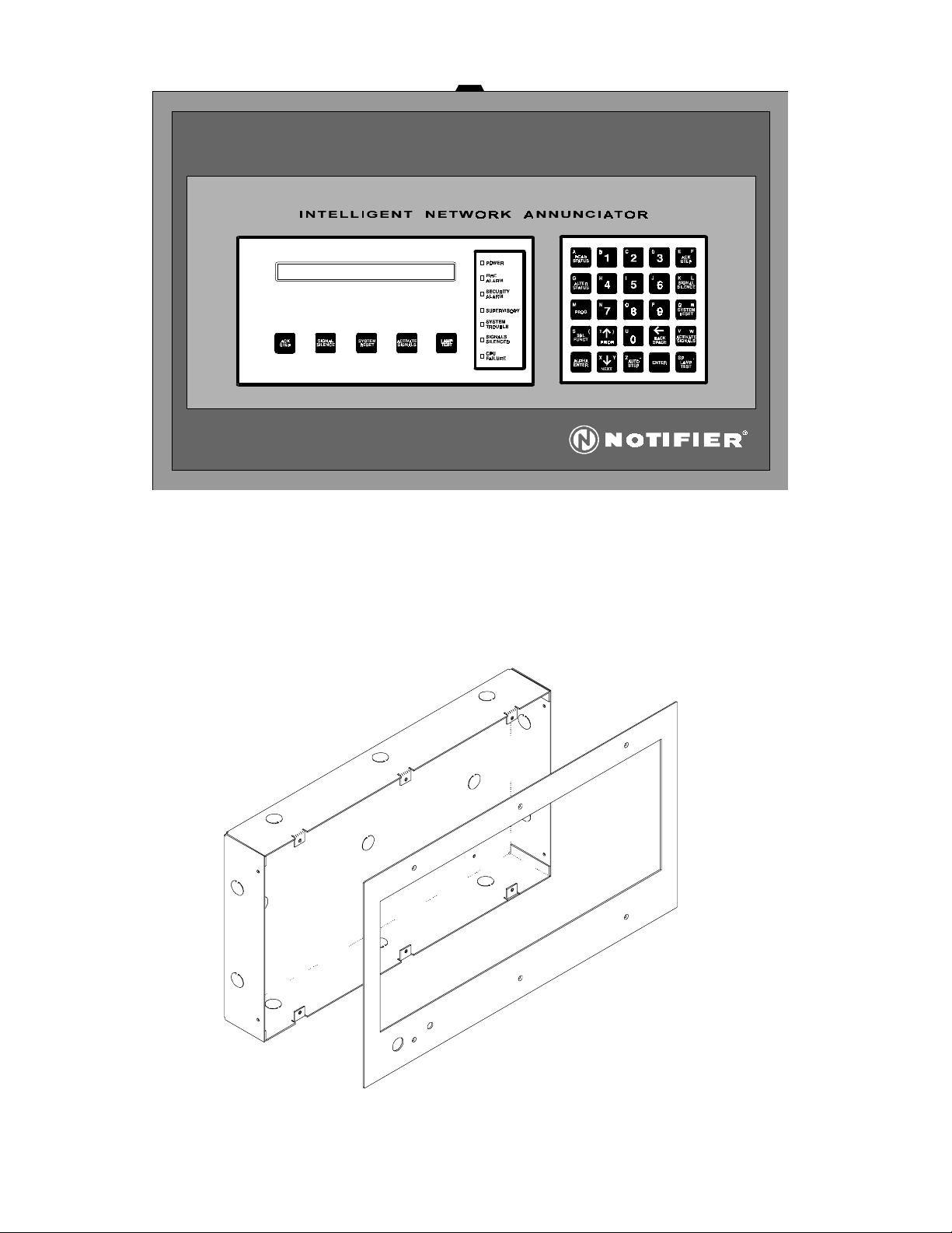
Figure 2.2.1-1 ABS-4D Cabinet
2.2.2 ABF-4 Cabinet
The ABF-4 Cabinet (refer to Figure 2.2.2-1) is a flush mounting annunciator box. Power must be supplied externally.
Knockouts are provided for use with a 1/2-inch (12.7 mm) conduit. The height of the cabinet is 9-15/16 inches (50.643 cm),
the width is 17-3/8 inches(44.133 cm), and the depth is 2-1/2 inches (63.5 mm). The dimensions of the trim plate (included
with the cabinet) are 11 inches (27.94 cm) high and 19-3/8 inches (49.213 cm) wide.
12
www.PDF-Zoo.com
Figure 2.2.2-1 ABF-4 Cabinet
INA 15092:I 05/30/01
Page 13

Annunciator Key Switch (AKS-1) or Shunt Plug
The AKS-1 provides access security for the control switches on the INA. The AKS-1 kit includes a key and hardware for
mounting to the ABF-4. Unless intended for use as the network point of acknowledgment, the AKS-1 or the shunt plug
(part number 08125) must be employed (refer to Figure 2.2.2-2). When employing the AKS-1, the switch must be mounted
to the ABF-4 trim plate. Plug the switch leads from the AKS-1 into Connector J3 on the INA. To disable the keypad, install
the shunt plug across both terminals of Connector J3 on the INA . Install the shunt on only one terminal of Connector J3
to enable the keypad. The INA keypad must be disabled via the AKS-1 or shunt plug when not in use.
J3
Trim Plate
(Rear View)
Figure 2.2.2-2 AKS-1 Mounted on an ABF-4 Cabinet
Shunt Plug
INA 15092:I 05/30/01
www.PDF-Zoo.com
13
Page 14

2.2.3 CAB-3 Cabinets
The INA can be mounted in a CAB-3 cabinet utilizing the Annunciator Dress Panel (ADP-4) (refer to Figure 2.2.3-1). This
CAB-3 cabinet comes in four styles; CAB-A3, CAB-B3, CAB-C3, and CAB-D3 and is suitable for use with internal power
supply.
ADP-4
The ADP-4 provides the cabinet mounting of the INA. The INA Control/Display Panel assembly is positioned on six studs
on the ADP-4 and secured by screws. The ADP-4 then hinge-mounts to a CAB-A3, B3, C3, or D3 cabinet by securing the
hinge assembly to the cabinet with two screws.
Figure 2.2.3-1 ADP-4 Annunciator Dress Panel
Vented Dress Panel (VP-2)
Use the VP-2 when the ADP-4 is installed in the top row of a NOTIFIER CAB-A3, B3, C3, or D3 cabinet. The VP-2 covers
the gap between the ADP-4 and the top of the cabinet and secures to the cabinet with two screws.
Figure 2.2.3-2 VP-2 Vented Dress Panel
2.3 EIA-232 COMMUNICATIONS CONNECTIONS
CRTs and printers may be utiliz ed wi th the IN A. CRT and pr int er co nne cti ons are made to term ina l TB 2 (r efe r to Figure 2.3-
1). TP I-232 modem s may be emplo yed for re mot e loc ati on of a CRT or pr int er. Th e CRT m ust remain within the pr ote cte d
premises and the keyboard must be removed or locked when not in use. CRT and printer connections are power limited.
Installation of the printer cable is detected, however some printer cable conductors are not supervised. In this manual, the
term PRN is used in reference to PRN-4 and PRN-5 printers.
Installing an Ancillary Device on the EIA-232 Communications Circuit
An ITE listed supplemental signaling device such as a printer or the PageNet-1 can be connected to the EIA-232 serial
printer port connection on the fire alarm system to provide a supplemental signaling capability. Additionally, some devices
such as PageNet-1 can be actuated by means of dry contacts from the fire alarm system. For more detailed instructions
pertaining to the installation of an ancillary device, refer to the specific device manual. (See Figure 2.3-5.)
14
www.PDF-Zoo.com
INA 15092:I 05/30/01
Page 15

INA
PRN Printer
CRT-2
Figure 2.3-1 INA Connections
Printer outputs are power limited and are not supervised. Where a printer is required, make connections in conduit (20 feet
(6.096 m) maximum) with an overall foil/braided-shield twisted-paired cable suitable for EIA-232E applications (refer to
Figure 2.3-4). The Keltron printer DIP switches should be set as shown in Table 2.3-1.
Switch Setting Switch Setting Switch Setting Switch Setting
SP1-1 OFF SP1-5 OFF SP2-1 OFF SP2-5 OFF
SP1-2 ON SP1-6 ON SP2-2 OFF SP2-6 OFF
SP1-3 OFF SP1-7 OFF SP2-3 OFF SP2-7 ON
SP1-4 ON SP1-8 ON SP2-4 OFF SP2-8 OFF
6able 2.3-1 DIP Switch Settings
INA 15092:I 05/30/01
www.PDF-Zoo.com
Figure 2.3-2 EIA-232 Communications Connection
15
Page 16

yalpsiDretnirPdednemmoceR
yalpsiDretnirPdednemmoceR
gnitteS
:TSUJDAR/L0 :IPCIPC01
:TNOFTFARDSH:PIKSSEHCNI5.0
:IPLIPC6:ETALUMENOSPE
:RETCARAHCCSECSE:O/I
gnitteS
LANOITCERIDIB
:REFFUB4-NRPROFK63
:YPOCNO
:LAIRES
:BAT-GCCIHPARG:DUAB0042
:YRTNUOCIICSAASU-E:TAMROF1,NEVE,TIB7
:RCOTUAFFO:LOCOTORPFFOX/NOX
:EGAUGNALHSILGNE:TESRETCARAHCDRADNATS
:RAETOTUAS1:OREZ.1SNO
:FLOTUAFFO
:NOITPOROLOCDELLATSNITON:KCOLNEMLLA
:NELMROF
:REPAP
:SENIL06=IPL6:1NIBSEHCNI27/21
:DRADNATS5.01EVITUCEXE
:2NIBEHCNI27/21
SEHCNI
5-NRPROFK04
POTS
16
www.PDF-Zoo.com
:ELGNISSEHCNI27/21
:ARTHSUPSEHCNI27/21
:ARTLLUPSEHCNI27/21
:LLORPAPSEHCNI27/21
:TPOPAPON
Table 2.3-2 Recommended PRN Printer Option Settings
INA 15092:I 05/30/01
Page 17

Keltron Printer
Model No. VS4095/5
50 Feet (15.24 m) Max
(Typical)
Wiring Distance Limited by
Cable Capacitance. Refer to
the EIA-232 Standard.
INA Connector TB2
nc
4
Plug this DB-25 Connector into the EIA-232 Port
of the PRN Printer.
Main Power Supply
MPS-24A/
MPS-24AE
TB3- 3
(+)
and
TB3-4 (-)
Figure 2.3-4 Keltron Printer Connections
Twisted-Pair
Twisted-Pair
TB2-6
TB2-5
TB2-6
TB2-4
DC IN -
Keltron Printer
Model No. VS4095/5
EIA-232 Reference
Transmit to Printer
EIA-232 Reference
Ready/Busy from Printer
+ DC IN
INA 15092:I 05/30/01
www.PDF-Zoo.com
PG-ancillary.wmf
TB2 on
the INA
Figure 2.3-5 Ancillary Connections
17
Page 18

2.4 THE CRT TERMINAL
The CRT Terminal, including keyboard, features an 80 column, 25-line display. Function keys allow you to execute INA
commands from the keyboard.
Primary and Secondary Power
The CRT requires 120 to 240 VAC, 50/60Hz primary power. A secondary power source (battery backup) is not provided; the
use of a separate Uninterruptable Power Supply (UPS), UL listed for Fire Protective Signaling, is recommended (refer to
Figure 2.5-1).
Electrical Specification
The electrical specifications for the CRT are as follows:
Vo lt ag e 90 264 VAC
Frequency 47 63 Hz
Current 0.5 0.2 A
Installation
Connection between the INA and the CRT is provided through an EIA-232 interface on the INA. Assemble a custom cable
for connection to the EIA port on the CRT. The Parallel (PAR), Auxiliary (SER2-AUX), and EIA (SER1-EIA) ports are located
on the back of the CRT-2 Monitor as shown below.
PAR SER2-AUX SER1-EIA
2.5 PRINTERS
A PRN printer may be connected to the INA to supply a hard-copy printout, documented with the time and date, of all status
ch anges with in t he system, local his tor y bu ffer, an d lo cal pro gra mming. The PRN may pro vid e up to 8 0 co lum ns o f data on
standard 9 inch by 11 inch tractor-feed paper. Outputs are power limited, but not supervised. Connections must be made
with overall foil/braided-shield twisted pair cable within 20 feet (6.096 m) in conduit. Near Letter Quality (NLQ) mode cannot
be employed on the PRN printer.
Installation
The PRN printer requires 120 VAC and 50/60Hz of primary power. A singular Uninterruptable Power Supply (UPS) 50 W
minimum is recommended and therefore a secondary power source (battery backup) is not provided (refer to Figure 2.5-1).
Printer Configuration
Refer to the documentation supplied with the PRN printer for menu control instructions. Table 2.5-1 contains recommended printer option settings.
18
www.PDF-Zoo.com
INA 15092:I 05/30/01
Page 19

Figure 2.5-1 120 VAC UPS Supervision for Printer/CRT
INA 15092:I 05/30/01
www.PDF-Zoo.com
19
Page 20

Negative Bar Positive Bar
The inverter is equipped with
automatic transfer. Refer to the
schematic in the instruction
manual for internal wiring.
Note:
DC Ou tput
Charger #1
TS-2
TS-1
AC
Load
DC/AC Inverter
Invert er
Failure
DC
Input
(Optional)
47k ELR
Charger #2
AC Line
Utility
Failure
To MPS-24A (P5)
Note: Wiring should be in the
same cabinet or use less than
3 feet (0.9 m) of conduit
DC Ou tput
TS-2
Use cable P/N 71033 from
MPS-24A connector P5 to
UPS. Cut and strip wires
as needed. Make all
connections in conduit
TS-1
Remot e
Equalize
Figure 2.5-2 Wiring Diagram for UPS Supervision for Printer/CRT
20
www.PDF-Zoo.com
Remot e
Sense (+)
Remot e
Sense (-)
Load Sharing
Rectifier
Failure
Current
Low
Remot e
Equalize
Load Sharing
Remot e
Remot e
Sense (-)
Sense (+)
Rectifier
Failure
Current
Low
Battery
SLC
UPS3a.cdr
Software Type ID
MTRB
MMX
INA 15092:I 05/30/01
Page 21

2.6 EIA-485 ACS ANNUNCIATOR INTERFACE
ACM-16AT
The Annunciator Control Module-16AT
contains 16 red alarm and 16 yellow trouble
LEDs, 16 momentary keypad switches for
controlling each point, a system trouble LED,
an ON LINE/POWER LED, and a local piezo
sounder with a silence/acknowledge switch
for audible indication of alarm and trouble
conditions at each annunciator.
AEM-16AT
The Annunciator Expander Module 16AT expands the ACM-16AT by 16 annunciator
points. Up to three of these expander modules can be supported by an ACM-16AT, to a maximum of 64 annunciator
points.
The ACM-32A
The Annunciator Control Module-32A contains 32 red alarm LEDs, a system trouble
LED, an ON LINE/POWER LED, and a local
piezo sounder with a silence/acknowledge
switch for audible indication of alarm and
trouble conditions at each annunciator.
AEM-32A
The Annunciator Expander Module-32A expands the ACM-32A by 32 annunciator
points. One expander module can be supported by an ACM-32A, providing a maximum of 64 points.
For more details on the Annunciator Control
System, refer to the ACS Manual.
The LDM-32
The LDM-32 Lamp Driver Annunciator Module provides 32 alarm or 16 alarm and 16
trouble lamp driver outputs, corresponding
to 32 annunciator points which can be connected to external devices such as a custom
graphic annunciator. When configured to
provide 16 alarm and 16 trouble outputs, 16
sw itc h in puts ar e availabl e for control of system functions such as signal silence, system
reset, and control module activation.
The LDM-E32
The Lamp Driver Annunciator Expander Module LDM-E32
expands the LDM-32 by 32 annunciator points (maximum of
64 points).
The LDM-R32
The LDM-R32 Relay Expander Module LDM-R32 provides
the LDM-32 or LDM-E32 with 32 dry Form-A (normally
open) contacts. The relay module replaces the lamp driver
outputs with relay outputs; one LDM-R32 for each LDM32 or LDM-E32.
For more details on the LDM-32 Series Lamp Drivers, refer to
the LDM Manual.
SCS-8*
The Smoke Control Station (SCS-8) module
uses eight groups of four annunciator points
for fan shutdown control or other heating,
ventilation or air conditioning functions.
SCE-8*
The Smoke Control Expander (SCE-8) is used
to expand the SCS-8 by an additional eight
ACKNOWLEDGE/
LAMP TEST
FAN
FLOOR
1
FAN
FLOOR
2
FAN
FLOOR
3
FAN
FLOOR
4
LOCAL
ALL AUTO
MANUAL
ON
ON
EXHAUST
FAN
AHU
AUTO
AUTO
FLOOR
FLOOR
5
1
OFF
OFF
TROUBLE
TROUBLE
ON
ON
FAN
AUTO
AUTO
FLOOR
6
OFF
OFF
TROUBLE
TROUBLE
ON
ON
FAN
AUTO
AUTO
FLOOR
7
OFF
OFF
TROUBLE
TROUBLE
ON
ON
FAN
AUTO
AUTO
FLOOR
8
OFF
OFF
TROUBLE
TROUBLE
groups of four annunciator points. Only one
expander can be used per SCS-8.
SCS-8L
The Smoke Control Lamp Driver Station (SCS-8L) module
uses eight groups of four annunciator points for fan shutdown control or other heating, ventilation or air conditioning functions. Must be mounted in custom graphic annunciator panel.
SCE-8L
The Smoke Control Expander (SCE-8L) is used to expand the
SCS-8L by an additional eight groups of four annunciator
points. Only one expander can be used per SCS-8L. Must be
mounted in custom graphic annunciator panel. Use of the
Smoke Control System is limited to HVAC mode when used
with the INA.
An SCS annunciator can physically connect to the INA or
fire panel, but not both.
For more details on the SCS Smoke Control System, refer to
the SCS Manual.
The UDACT
The UDACT is capable of transmitting the status of software
zones (Alarm and Trouble), System Trouble, Panel Off-Normal, Supervisory, Bell Trouble, Low Battery, and AC Fail. The UDACT
communicates vitalsystem status
including: Independent zone fire
alarm, Independent zone non-fire
alarm, Independent zone trouble,
Independent zone supervisory,
AC (mains) Power Loss (programmable), Low Battery and Earth
Fault, System Off-Normal, 12 or 24
hour test signal, Abnormal Test
Signal per new UL requirements
and EIA-485 Communication Bus
Failure.
*NOTES: 1. In the current release, smoke control annunciators (SCS-8/SCS-8L) are only supported in HVAC
manual mode. 2. The SCS-8 and SCS-8L firmware has been
updated in conjunctionwith Software Release 2.8. Software Part Numbers 73631 and 73845 are not compatible
with INA combinations after M2.7. Part #SCSV2.8 is not
compatible with FACP/INA combinations prior to M2.8.
INA 15092:I 05/30/01
www.PDF-Zoo.com
21
Page 22

EIA-485
Reference
Slide Switch 1 to the left when the INA is at
one end of the EIA-485 circuit.
1
2
3+
TB1
4-
5+
67
SW1
INA
EIA-485 circuit characteristic impedance of twisted pair wiring should be approximately 120 ohms.
43-
TB2
2+
1+
P3
AMG-1
ACM-16AT
See Appendix A of the AM2020/AFP1010 manual for EIA-485 circuit ratings and limitations
Figure 2.6-1 EIA-485 to INA Connections
43-
TB2
2
1+
ACM-32A
EIA485INA.cdr
22
www.PDF-Zoo.com
Slide Switch 1 to the right (away from the
connector) when the INA is not at the
beginning or end of the EIA-485 circuit.
Figure 2.6-2 INA/EIA-485 Circuit Terminating Diagram
INA 15092:I 05/30/01
Page 23

The EIA-485 Reference (TB1-1) on the INA must be connected to any ACS device that is not within the same cabinet or is
not powered by the INA power supply. Connect TB1-1 of the INA to: ACM-16AT/LDM-32 at TB1-4, AMG-1/E power
supply (MPS-24A/MPS-24AE) at TB2-2, SCS-8L at TB1-4, LCD-80 at P1-4, RPT485W Ref. A at TB1-5, RPT-485W Ref. B at
TB2-5, or RPT-485WF Ref. A at TB1-5.
TB1
P3
P3
P3
P3
Figure 2.6-3 EIA-485 Circuit Maximum INA/AMG Configuration
An AMG-1 cannot be installed in another network node if one or more AMGs has been installed in an INA. More than one
INA may contain AMGs if the INAs are not located in the same group (see Chapter Three, Groups and Linking). Up to four
AMGs may be installed in one INA (see Figure 2.6-3).
The Remote Page function cannot be used when an AMG and FFT have been installed in an INA. An ACM-16AT
annunciator (set to address 1) is required to operate the AMG(s) and speaker circuits in the INA. Points on the ACM-16AT
may act as shadow points (see About Annunciator Operation with the INA in Chapter Two). This annunciator may be
programmed into another node but does not physically need to be installed at any other node. When there is no AMG
installed in any INA, the use of AMGs and ACM-16AT annunciators at the local panel is permitted in the usual fashion. See
the Voice Multiplex System Manual.
2.7 POWERING THE INA
The INA may be powered from one of three different sources, a Main Power Supply MPS-24A/MPS-24AE mounted in the
same cabinet, a MPS-24B/MPS-24BE in the same cabinet, or an externally mounted power supply.
INA 15092:I 05/30/01
www.PDF-Zoo.com
23
Page 24

2.7.1 The Main Power Supply (MPS-24A or MPS-24AE)
The MPS-24A/MPS-24AE may be mounted externally or in the same cabinet (CAB-3) as the INA. When powered from an
MPS-24A/MPS-24AE mounted in the same cabinet, power is supplied to the INA through the main power harness (from P2
or P4 on the MPS-24A/MPS-24AE to J4 on the INA). For calculation of the primary and secondary power requirements refer
to Appendix A of this document.
Four-Wire Smoke Detector Power
Secondary Power
27.6 VDC, supervised and power-limited.
Fast charge = 2 amps, trickle charge = 20 mA.
Battery -
Battery +
Primary Power
120 VAC, 50/60 HZ, 1.8 amps max. (MPS-24A)
220/240, 50/60 HZ, 0.9 amps max. (MPS24AE)
Neutral Out Hot In
Neutral In Hot Out
Earth Ground
Connect to chassis via
a Grounding Cable
Assembly.
+ -
24 VDC (200 mV ripple), 1 amp max. Filtered and resettable.
Power-limited but must be supervised via a Power Supervision Relay.
Notification Appliance/Annunciator Power
+
Power-limited, filtered, non-resettable, 3 amps
-
(in alarm) max. JP5 may be cut to convert this
notification appliance power (TB3 Terminals 3
and 4) to a resettable, 2-amp maximum circuit.
This output can also be used to power ACS
series annunciators (do not cut JP5).
Power Supervision Ribbon Cable Connector
Connect to J9 on the INA.
Power Harnesses (P2, P4)
Connect to J4 on the INA (3 amps max, P2 and P4
combined) or any other module or board requiring
internal power.
Cut JP1 to disable the battery charger
when employing the CHG-120 remote
battery charger.
Figure 2.7.1-1 Field Wiring the MPS-24A/MPS-24AE
Battery Fuse (10A, 3AG)
MPM-2 Voltmeter/Ammeter Connector
Not used with the INA
Cut R27 to disable
Earth Fault Detection.
Earth Fault Detection
is required in Canada.
LED Indicators
Earth Ground Fault
Battery Failure
AC Power Failure
NiCad High Charge Rate
(not supported by INA)
JP5: Cut to make
Notification appliance
power on TB3 Terminals
3 and 4 a resettable 2amp max circuit.
JP2: Must be cut,
otherwise a short on the
Notification appliance
power circuit (Terminals
3 and 4) would register
incorrectly as a loss of
primary (AC) power.
24
www.PDF-Zoo.com
INA 15092:I 05/30/01
Page 25

2.7.2 THE MAIN POWER SUPPLY (MPS-24B OR MPS-24BE)
The MPS-24B/MPS-24BE may be mounted externally or in the same cabinet (CAB-3) as the INA. When powered from a
MPS-24B/MPS-24BE mounted in the same cabinet, power is supplied to the INA through the main power harness (from P2
on the MPS-24B/MPS-24BE to J4 or TB3 on the INA). For calculation of the primary and secondary power requirements,
refer to Appendix A.
Four-Wire Smoke Detector/Annunciator Power
24 VDC (200 mV ripple), 200 mA max. Filtered and resettable*.
Power-limited but when used for four-wire detectors, must be supervised by a UL listed Power Supervision Relay. Power run to
ACS Annunciators is inherently supervised.
_
+
Notification Appliance Power
24 VDC power-limited, RMS-regulated, nonresettable, 2.0 amps (in alarm) max. Power is supervised by output module (such as an ICM-4). Not
for annunciators!
120 VAC, 50/60 HZ, 1.8 amps max. (MPS-24B)
220/240 VAC, 50/60, 0.9 amps max (MPS-24BE)
Neutral
Earth Ground
Connect to chassis with a
Grounding Cable Assembly
(Cable # 71073).
Primary Power
Cut R55 to
Disable
Earth Fault
Detection.
Hot
Power Harness
Connect to J4 on the
INA
+
_
Secondary Power
27.6 VDC, 6.5 to 17 AH. Supervised and powerlimited. Fast charge =750mA max., trickle charge
= 20 mA (typ).
Battery +
Battery -
Power Ribbon Connector
Connect to J9 on the INA
LED Indicators
Earth Ground Fault
Battery Fail
AC Power Fail
Not used on the INA
INA 15092:I 05/30/01
www.PDF-Zoo.com
Cut JP2 to disable the battery charger
when employing the CHG-120 Remote
Battery Charger.
Figure 2.7.2-1 Field Wiring the MPS-24B/MPS-24BE
JP3 must be cut for
use with the INA.
* Cut JP1 to make FourWire Smoke Detector
Power on TB2 Terminals 1
and 2 a non-resettable circuit.
25
Page 26

2.7.3 REMOTE SUPPLY
When the INA is powered from a source external to the INA cabinet, it must be connected as illustrated in Figure 2.7.3-1.
An optional connection is illustrated, and is normally used only when the INA is being powered from an external source.
For calculation of the primary and secondary power requirements, refer to Appendix A of this document.
J4
Keltron Printer Power (Model
No. VS4095/5)
To Other Devices*
+
-
MPS-24A/MPS-24AE - TB3 Terminals* 4 3
MPS-24B/MPS-24BE - TB2 Terminals* 4 3
Nonresettable 24 VDC remote
power supply listed for Fire
Protective Signaling*
-
Figure 2.7.3-1 INA 24 VDC External Power Connection
TB3
TB2
TB1
SW1
+
* Warning
When powering ACS Series Annunciators or other
EIA-485 devices from these terminals use separate
wires. Do not "T-Tap" or damage may result during
abnormal conditions.
+
2.8 APPLYING/REMOVING POWER TO THE INA
After completing the proper installation of all cables and components, apply power in the following manner:
Apply AC power
Connect the battery/secondary power terminals as described in Section 2.7.3 of this manual
When servicing the INA, perform the following steps before removing or connecting any power or supervisory cables:
Remove all EIA-485 connections
Remove battery/secondary power
Remove AC power
Wait 60 seconds
WARNING: Never remove or install boards, internal cables or components with power applied. Failure to follow the
procedure outlined above can result in irreparable damage to the system components. This damage may adversely affect
the operation of this control unit but its effect may not be readily apparent.
26
www.PDF-Zoo.com
INA 15092:I 05/30/01
Page 27

INA
I
NTELLIGENT NETWORK ANNUNCIATOR
INA 15092:I 05/30/01
www.PDF-Zoo.com
CHAPTER TWO
OPERATION
27
Page 28

INTELLIGENT NETWORK ANNUNCIATOR
CHAPTER TWO OPERATION
ABOUT NVRAMS
Improper power down or up of the INA causes the NVRAMS to set their internal partitions disabling write capability. The
INA software verifies the state of the partitions on the nonvolatile static RAMs on initial power on. If a NVRAM problem
has been detected on the power up cycle, the INA will display the error message, TROUBL CATASTROPHIC INA NON
VOLATILE RAM FAILURE. If this condition occurs, call the factory for immediate assistance.
ABOUT THIS CHAPTER
This chapter covers the operation of the INA and the control features available to the operator presented through the
perspective of the keypad and the 80 character LCD.
ABOUT THE PASSWORDS
The INA functions in one of three levels: Operational Level, Level One, and Level Two. In Operational mode, the
operator can perform the following keypad or menu-displayed functions:
Acknowledge alarms, troubles, and restorations (clears).
View acknowledged alarms and troubles.
Silence the sounding of fire alarm notification appliances.
Simultaneously reset all panels which are associated through programming.
Point Read Status for network devices and local INA annunciator points
Test the INA LED indicators, Liquid Crystal Display (LCD), terminal, and printer.
View or print the event history stored in nonvolatile memory.
Access to keypad or menu levels one and two require entry of specific passwords. These levels allow an authorized
programmer to initialize or alter the programming of the INA. Entry requirements are defined as follows:
A Level One password is required for Alter Status.
A Level Two password is required for Programming.
If the main operator of the system requires access to a function which is password protected, contact the NOTIFIER
Distributor who installed the system for the required password(s). For more information on programming or altering the
status of the INA, refer to Chapter 3 (Programming) of this document.
Whenever the operator selects a menu, the INA begins a one-minute timer. If no key is pressed during this minute, the
function selected will be aborted and control will return to the INA state prior to selection of that menu.
An AKS-1 Annunciator Keyswitch is required for each INA unless it is installed in a lockable cabinet such as a CAB-3
series. The AKS-1 is used to enable and disable the INA keypad. Only one INA can have the keypad enabled; all other INA
keypads must be disabled using the AKS-1 or the shorting plug shipped with the INA on J3. If an NCS is installed on the
network, all the INA keypads must be disabled.
ABOUT THE SOFTWARE
Depending on the particular release of software in your system, some menu functions and system features may not be
operable. If you attempt to execute a function that is not operable, the panel will respond with the message "FUNCTION IS
NOT ENABLED".
Contact your NOTIFIER Distributor for information on the latest software features available for the INA.
28
www.PDF-Zoo.com
INA 15092:I 05/30/01
Page 29

ABOUT GROUPS AND LINKING
The INA may be programmed to link to a user defined group of network nodes or to all nodes on the network
(autoprogramming). If the operator programs the INA for a defined group of nodes, the INA will only respond to that group
and will ignore messages received from any other nodes, including alarm and trouble indications, off-line indications, etc.
The INA will only transmit commands (acknowledge, signal silence, reset, read/alter status, etc.) to the group of nodes
linked to the INA. The group and linking feature does not affect time synchronicity with the INA, and therefore, if the INA
is the master time keeper of the network, it will transmit the time-synch message to all nodes on the network whether or not
they are linked to the INA.
Autoprogramming
Autoprogramming the INA links the INA to all nodes on the network. If autoprogramming is selected, all nodes communicating on the network will be programmed into the INA's network map. Any nodes previously linked to the INA that are no
longer communicating on the network will be removed from the INA's network map during autoprogramming.
Overlapping Groups
Network nodes may exist in two separate INA groups. If INAs overlap in a group, they must be programmed into each
other's group. Refer to the example in Figure 2.0-1 bel ow.
NCS
INA
(Node 3)
Group = Nodes 2,4,5,6,7,8
(Node 2)
INA
(Node 4)
Group = Nodes 2,3,8,9,10
FACP
(Node 5)
FACP
(Node 6)
FACP
(Node 7)
FACP
(Node 8)
FACP
(Node 9)
FACP
(Node 10)
Figure 2.0-1: Overlapping Nodes with the INA Groups and Linking Feature
In the figure above, Node 3 has been programmed to include Nodes 4,5,6,7,8, and the NCS in its group. Because the
INA at Node 3 includes the INA at Node 4 in its group, Node 4 must include Node 3 in its group. This allows reporting
nodes on the network to transmit signals to each other. The NCS communicates with all nodes on the network and
therefore must be programmed into every INA group. For more information on the NCS, refer to the NCS Manual
mentioned in the Related Documentation Chart at the beginning of this manual.
INA 15092:I 05/30/01
www.PDF-Zoo.com
29
Page 30

ABOUT ANNUNCIATOR OPERATION WITH THE INA
The INA's Annunciator Control System (ACS) has the ability to display status on any network fire alarm control panel
(FACP). The ACS may be used for simple zone annunciation or may be used to control the state of control devices
mapped to a FACP's local annunciator point. The INA ACS displays point information for AM2020/AFP1010 FACPs
and zone information for AFP-200s. NOTES: 1. In the current release, smoke control annunciators (SCS-8/SCS-8L) are
only supported in HVAC mode. 2. The SCS-8 and SCS-8L firmware has been updated in conjunction with Software
Release 2.8. The new SCS firmware is not backward compatible with older revisionns of software.
Annunciator Points
INA annunciator points can map to any network zone or mimic an AM2020/AFP1010 FACP local annunciator point.
When an INA annunciator point mimics or follows the state of a predetermined and programmed remote node annunciator point, the point is referred to as a shadow annunciator point. Information displayed on the INA shadow annunciator
point is identical to what is displayed on the FACP's annunciator. Programming to determine whether the ACS point is
an input or output point is performed on the FACP. SCS annunciator points and AMGs may be mimicked by an INA
shadow annunciator point, but SCS annunciators and AMGs cannot physically be located at both the INA and a fire
panel in the same INA group.
INA ACS points may be mapped to AFP-200 zones. In the AFP-200 the individual ACS points are the zones. When the
AFP-200 zone becomes activated, the INA ACS point mapped to that zone becomes activated. Note: If an FACP's local
annunciator point or zone is mimicked by an existing INA shadow ACS point that corresponds to a network node not
included in the INA's group, that ACS point will not function.
Audio Message Generators as Annunciator Panels
Each INA in the network can communicate with 1 to 32 annunciator panels. Each annunciator panel can have up to 64
points. The ACS can also communicate with devices that emulate annunciator panels such as Audio Message Generators.
When using an AMG for networked voice evacuation, pressing the All Call button on the AMG which is connected to the
INA, will cause a network All Call message to be sent to all FACPs in that INA's group. This message will cause the
FACPs in the group to activate all installed SPKR circuits. Subsequently, depressing the AMG All Call button will
cause all installed SPKR circuits to deactivate. If a shadow INA ACS point for networked voice evacuation is mimick-
ing an ACS point at an FACP, the annunciator should be programmed into the FACP but does not need to be physically
installed. If an AMG is installed at the INA, it cannot physically be installed at any other node in the INA's group.
IMPORTANT!
All Call on the INA will only work for the nodes programmed into the INA. If multiple INAs employing AMGs
exist on the network, the group of nodes programmed into the INAs must not overlap. If the groups overlap, the
possibility exists of one INA initiating All Call and another INA turning it off. To avoid this possibility, each INA/
AMG must only affect a specific group of network nodes that no other INA/AMG can affect.
Annunciator Mapping
A network zone can be mapped to any annunciator point on the INA. There are no restrictions to node or zone mappings.
The annunciator point will then display the current state of the network zone. Restrictions exist regarding the use of
some ACS devices with the INA. These restrictions are described in detail in the Installation and Programming chapters.
Manual Mode
If manual mode operation is used for an annunciator or SCS then all annunciator control points must be mapped/shadowed to the same FACP mode for each annunciator address.
ABOUT THE DISPLAY TIME
The INA has a time field in the text displayed for each event that occurs in the system.
All Systems Normal: During periods of no activity, the time field reflects the current time.
Single, Unacknowledged Event: When an event has occurred but has not been acknowledged, and no other event has
occurred, the CRT terminal and the INA will display the time that the event occurred.
Multiple, Unacknowledged Events: The display will show the actual time that the first unacknowledged event occurred.
After all unacknowledged events have been acknowledged with the Acknowledge command, the INA will display the
highest priority acknowledged event on the network with the INA's internal current time. This time does not represent the
time the event occurred. Only the history buffer retains the date and time an event occurred.
Single/Multiple Previously Acknowledged Events: The time shown for an acknowledged event is the time at which that
event was last placed in the display by activation of the ACK STEP key (not the time at which the event occurred). Only the
history buffer retains the date and time an event occurred.
30
INA 15092:I 05/30/01
www.PDF-Zoo.com
Page 31

ABOUT THE BACKSPACE KEY
The Backspace key serves two purposes:
1. At a menu prompt, pressing "aborts" the selection of that menu.
2. Wh en ent erin g dat a o r m akin g a sel ecti on fr om a men u, pre ssi ng era ses th e las t c hara cte r, or me nu
choice entered.
BACK
SPACE
➪
BACK
SPACE
➪
ABOUT THE PRINT TIME
Output from the printer for a particular event (alarm, trouble, acknowledgment, etc.), includes the time the event was sent
to the printer, which in most cases is identical to the time the event occurred. In extreme cases, when many events have
occurred within a few seconds, the time printed for a particular event may differ from the actual event time by up to one
minute. After events have been acknowledged, only the event history buffer (which may be printed) and the system printer
will provide a record of the time at which events occurred.
ABOUT PRIORITIES
Every AM2020/AFP1010, AFP-300/400 and AFP-200 event the INA displays is prioritized. Security alarms will increment
the trouble counter on the terminal status line of the CRT. The INA processes and displays AM2020/AFP1010, AFP-300/
400 and AFP-200 events under the following priorities (the highest priority is displayed first and the lowest priority is
displayed last).
1) Fire Alarms 9) Cleared Fire Alarms
2) Security Alarms 10) Cleared Security Alarms
3) Supervisory Signals 11) Cleared Supervisory Signals
4) Device Troubles 12) Cleared Device Troubles
5) Disabled Zones 13) Cleared Disabled Zones
6) System Troubles 14) Cleared System Troubles
7) Annunciator Troubles 15) Cleared Annunciator Troubles
8) Local INA Troubles and 16) Cleared Local INA Troubles and
Remote INA and NRT Troubles Remote INA and NCS Troubles
In addition, detectors have a higher priority than modules within each detector/module category; the lower the address, the
higher the priority (see list below). The display of certain events can be preempted by others at the time they are acknowledged. Pay careful attention to the display when acknowledging events. The Node Address will determine priority only if
the same event on the same point occurs on multiple nodes. In that case, the event on the node with the lower node address
has the highest priority.
Node 1, Loop 1 Detector 1, Loop 1 Detector 2, Loop 1 Detector 3 . Loop 10 Detector 99 (followed in priority by)
Node 1, Loop 1 Module 1, Loop 1 Module 2, Loop 1 Module 3 . Loop 10 Module 99 (followed in priority by)
Node 1, Zone 1, Zone 2, Zone 3 . Zone 240 (followed in priority by)
Node 1, System Trouble Indication (in Hex) T00, T01, T02 . TFF (followed in priority by)
Node 1, Annunciator Trouble Indication (in Hex) N00, N01, N02 . . NFF
ABOUT ADDRESSES
For certain functions such as READ STATUS, the operator must enter a device, software zone, or annunciator point
address. Leading zeroes are not required. The address assumes the following format:
LXX(D/M)YY, ZXXX or AXXPYY
SLC Loop
Enter "L" followed by 1 to 10 for AM2020.
Enter "L" followed by 1 to 4 for AFP1010.
SLC Loop Device
Enter "D" for an intelligent detector or "M" for an
addressable module followed by an address in
the range 1 to 99.
INA 15092:I 05/30/01
Software Zone
Enter "Z" followed by 1 to 240.
Annunciator Point
Enter "A" followed by 1 to 32 for the annunciator module address, then "P" followed by the module point 1 to 64.
31
www.PDF-Zoo.com
Page 32

SECTION 1 THE KEYPAD AND LIQUID CRYSTAL DISPLAY (LCD)
1.1 N
ORMAL OPERATION
In a normal operating condition, when no alarms or troubles exist, the system will display the following:
Custom 40-Character User Label
ANY CUSTOM MESSAGE
ALL SYSTEMS NORMAL 04:32P 03/01/00
Current Time and Date
Hour:Minute Month/Day/Year
The operator can perform the functions associated with the following keys without having to enter a password:
The READ STATUS and the SPL FUNCT keys are described in the following pages.
A
READ
STATUS
ACK
STEP
(a description of the READ STATUS key follows)
History Buffer and
Print Functions
S (
SPL
FUNCT
SIGNAL
SILENCE
SYSTEM
RESET
Not Enabled at this Time
ACTIVATE
SIGNALS
LAMP
TEST
32
www.PDF-Zoo.com
INA 15092:I 05/30/01
Page 33

1.2 READ STATUS
The Read Status feature provides local INA and network device status information. If a new event, such as an alarm or
trouble message, is received by the INA during Read Status, the Read Status function will be aborted and the event will
be displayed. To execute Read Status:
Press and the display will show:
PRESS@1=PSYS,2=PTREAD,3=NETPTREAD
:
Enter 1 for Display System Configuration. This selection provides information on any of the system parameters programmed into the INA, such as NFN node address, MIB-W communication thresholds, keyswitch enabled, annunciator
modules installed, etc.
Enter 2 for Point Read. This selection provides information on the status of any annunciator point programmed into the
INA.
Enter 3 for Network Point Read. This selection provides information on the status of any device or zone on the network.
Only devices and zones on nodes that have been programmed into the INA can be accessed under the Read Status
command.
Note: Read Status is not supported on the AFP-200.
A
READ
STATUS
A
READ
STATUS
READ
DISPLAY SYSTEM CONFIGURATION
STATUS
MENU OPTION 1
Selecting 1 from the Read Status Menu allows the operator to review the various system parameters entered into the INA
from the following System Configuration Menu:
INA 15092:I 05/30/01
www.PDF-Zoo.com
PRESS@1=NFN,2=KEY,3=CABLE,4=ANN,5=UDACT,
6=EXTEQ,7=LOCP :
33
Page 34

Once a menu choice is entered, the status for that menu choice will be displayed.
MENU CHOICE STATUS DISPLAY
1=SYSTEM,2=NETMAP
1
1=SYSTEM: Option 1 under the Read Status NFN option, displays system parameters as illustrated in the next display
screen..
ADDR = Network Node Address
MIBA = Channel A MIB Threshold Setting
MIBB = Channel B MIB Threshold Setting
PORTS = Single or Dual Port Monitoring
ADDR=211,MIBA=H,MIBB=L,PORTS=1
2=NETMAP: Option 2 under the Read Status NFN option, displays all the nodes programmed into the INA as illustrated in the next two display screens. The user may have to press ENTER to scroll through all nodes.
2
3
THE FOLLOWING NODES ARE PROGRAMMED IN
(PRESS ENTER TO CONTINUE UNTIL DONE)
001,002,045,078,009,078,240
Key = Is the key switch enabled?
KEY=Y
Cable = Is local power supply monitoring enabled?
CABLE=N
34
www.PDF-Zoo.com
INA 15092:I 05/30/01
Page 35

4
Due to its size, the Annunciator Read Status display is separated into two screens, as illustrated below. Pressing ENTER
invokes the next display.
THESE ANNUNCIATORS ARE INSTALLED:
(PRESS ENTER TO CONTINUE UNTIL DONE)
1=Y, 2=N, 3=N, 4=N, 5=Y, 6=Y, 7=N, 8=N,
9=Y,10=N,11=N,12=Y,13=Y,14=Y,15=N,16=N,
17=Y,18=N,19=N,20=N,21=Y,22=Y,23=N,24=N,
25=Y,26=N,27=N,28=Y,29=Y,30=Y,31=N,32=N,
UDACT=01
5
UDACT= Base address of the UDACT (blank for none installed)
TSUPR = Is the connection to the terminal
supervised? If TSUPR = N, the terminal will
not audibly indicate style changes (i.e., no
bell characters will be sent).
PMON = Is the connection
to the printer monitored?
PAGER = Is Page-1
enabled?
TSUPR=N,PMON=N,PAGER=N,MODEM=N
6
MODEM=Is Modem
enabled?
Is the INA programmed for
Receive Mode?
RECEIVE MODE=N
7
NOTE: The INA is programmed for Block Acknowledge or Receive Mode. If programmed for Receive Mode, Block
Acknowledge is disabled.
INA 15092:I 05/30/01
www.PDF-Zoo.com
35
Page 36

READ
POINT READ
STATUS
MENU OPTION 2
Selecting 2 from the Read Status Menu allows the operator to review annunciator point parameters entered into the INA.
The INA prompts the operator for the address of the point to be read.
ENTER AXXPYY FOR PT. STATUS
(BCKSPC TO ABORT) :
Upon entering the address, the INA will display a distinct screen format as illustrated below:
Annunciator Points
Status: Disable, Alarm/On, Trouble, Alarm/
On/Trouble, Normal or Blank
NORMAL ANNUNCIATOR ONE
NETWORK ANNUN POINT N001 A1P1
Software Type ID
20-Character Custom Label
Node Mapping
Point Address
READ
NETWORK POINT READ
STATUS
MENU OPTION 3
Selecting 3 from the Read Status Menu allows the operator to view the status of any device, annunciator panel, annunciator
point, or zone on the network for all AM2020/AFP1010 nodes linked to the INA. The INA prompts the operator for the
address of the network point to be read:
ENTER NXXXLYY(D/M)ZZ, NXXXZYYY, NXXXAYY,
NXXAYYPZZ (BCKSPC TO ABORT) :
Only nodes programmed into the INA can be accessed with this feature. If the operator attempts to use the Network Point
Read function on a node that is not present on the network system or not programmed into the INA, the following error
message will occur:
After the operator enters the desired point, the display will indicate that a Read Status is in progress until the point
information is received. If the INA does not receive a message from the network node within 20 seconds, the INA will
display the error message above followed by an "All Systems Normal" message or system event (if present). Once the
information is received, it will be displayed for one minute or until the operator presses ENTER, at which time the CBE
information for that point will be displayed for one minute. If the point is a reverse zone, the CCBE information will be
displayed for one minute.
36
www.PDF-Zoo.com
NODE XXX IS OFF-LINE OR NOT PROGRAMMED
INTO THE SYSTEM
INA 15092:I 05/30/01
Page 37

The information received by the INA from the network node during a Network Point Read Status, will be displayed in a
distinct screen format, depending on the particular type of device being read, as illustrated below and on the following
pages.
If the operator presses the Backspace key at any time during the Read Status, the Read Status will abort and all messages
received from the network node will be ignored by the INA. The INA will then display the information that was displayed
prior to the Read Status operation.
Detectors
20-Character Custom Label
Status: DISABL, ALARM:, TROUBLE, NORMAL
Node Address
STATUS N130 PHOT COMPUTER ROOM PHOTO
D A T K V000 M 034 L02D26
Type ID
D = Disabled
A = Alarm
T = Trouble
K = Tracking
Control Modules
Status: DISABL, ON, TROUBL, OFF,
OFHOOK, NORMAL
STATUS N130 CON COMPUTER ROOM BELL
D CF A T W S L02M36
Device Disabled
Control Module
CO = On
CF = Off
Device Activated
Node Address
Device in
Trouble
Verification
Counter
Type ID
Participates in
Walk Test
Sensitivity Setting
Percentage of
alarm threshold
Signal Silence
Enabled
Device
Address
20-Character Custom Label
Device
Address
INA 15092:I 05/30/01
www.PDF-Zoo.com
37
Page 38

Monitor Modules
Fire Status: DISABL, ALARM:, TROUBL, NORMAL
Non-fire and Security Status: DISABL, ON, TROUBL, OFF
Type ID
Node Address
STATUS N130 SACM COMPUTER ROOM DOOR
D MO A T K L04M12
20-Character Custom Label
Device Disabled
Module On
(Non-fire and Security only)
Device in Alarm
Software Zones
Status: DISABL, ALARM:, TROUBL, NORMAL
Node Address
STATUS N130 FZON ATTIC DEVICE ZONE
D A T Z024
Zone Disabled
Zone in Alarm
Device in
Trouble
Type ID
Zone in
Trouble
Tracking
Selected
Device
Address
20-Character Custom Label
Zone
Address
Annunciator Points
Status: ON, TROUBL, OFF, REQEST or blank
38
www.PDF-Zoo.com
20-Character Custom Label
Type ID
Node Address
OFF N130 AZON THIRD FLOOR ZONES
A01P23
Annunciator Point Address
INA 15092:I 05/30/01
Page 39

SECTION 2 FIRE ALARMS
The following example illustrates the system format used to display fire alarm conditions received from an AM2020/
AFP1010, AFP-300/400 or AFP-200 system. For more information refer to the AM2020/AFP1010 Manual and for type ID
definitions see the Software Type ID section of the AM2020/AFP1010 Programming Chapter. Messages on the AFP-200 or
AFP-300/400 fire alarm panels are different than those displayed on the INA or NCS (see Table 2.0-1).
SEPYTECIVED
rotceteDeludoM
THPFNMCN
RHTFLUPM
REHTNOM
DNOILLUP
HNOINOCS
NOIRPUS
TOHPTAW
TAEHTCAD
Node Address
(Range is from 1 to 240)
Device Status
ALARM: N211 PHOT@@@@@@@@ COMPUTER ROOM
FOURTEENTH FLOOR 04:32P 03/01/00 124
Software Zone Label
of the first software zone that
the device was mapped to
during programming of the
network node.
RSALKMSM
TLUMTHM
FERA)knalb(
VOHPRNAM
VNOILDRM
BMOC
USPS
Time and Date
Hour:Minute Month/Day/Year
Custom Device Label
that was entered during
programming of the AM2020/
AFP1010 network node.
Device Address
(Range is from 01-99)
Loop Number
(Range is from 1 to 9, with 0=Loop 10)
NOTE: The piezo sounder will pulse for fire alarm conditions.
INA 15092:I 05/30/01
www.PDF-Zoo.com
39
Page 40

002-PFA
.D.IepyT
002-PFA
egasseM
DCLANI
egasseM
SCN
egasseM
YROSIVREPUSEVITCA:detavitca
40M00/60/3P04:10
yrosivrepuS
40M
50M00/60/3
repmaT
60M00/60/3P70:20
eriF-noN
70M00/60/3P33:20
trelAdrazaH
70M
80M00/60/3P12:30
lortnoCeriF
90M00/60/3P70:30
hctiwStrobA
90M
01M00/60/3P43:40
esaeleR.naM
01M
21M
noMelbuorT
21M
lebalenozlebaltniopmotsuc
40100/60/3
YROSIVREPUSLBUORT:elbuort
lebalenozlebaltniopmotsuc
00/60/3P70:20TIUCRICNEPO
motsucREPMATEVITCA:detavitca
P02:20lebalenozlebaltniop
50100/60/3
motsucREPMATLBUORT:elbuort
NEPOlebalenozlebaltniop
50M00/60/3P34:20TIUCRIC
ERIFNONEVITCA:detavitca
lebalenozlebaltniopmotsuc
60100/60/3P70:20
motsucERIFNONLBUORT:elbuort
NEPOlebalenozlebaltniop
60M00/60/3P12:20TIUCRIC
TRELADRAZAHEVITCA:detavitca
lebalenozlebaltniopmotsuc
70100/60/3
TRELADRAZAHLBUORT:elbuort
lebalenozlebaltniopmotsuc
00/60/31P74:20TIUCRICNEPO
LORTNOCERIFEVITCA:detavitca
lebalenozlebaltniopmotsuc
80100/60/3P12:30
LORTNOCERIFLBUORT:elbuort
lebalenozlebaltniopmotsuc
80M00/60/3P53:30TIUCRICNEPO
HCTIWSTROBAEVITCA:detavitca
lebalenozlebaltniopmotsuc
90100/60/3P70:30
HCTIWSTROBALBUORT:elbuort
lebalenozlebaltniopmotsuc
00/60/3P71:40TIUCRICNEPO
ESAELER.NAM:MRALA:detavitca
lebalenozlebaltniopmotsuc
01100/60/3P43:40
ESAELER.NAMLBUORT:elbuort
lebalenozlebaltniopmotsuc
00/60/3P85:40TIUCRICNEPO
NOMELBUORTLBUORT:detavitca
lebalenozlebaltniopmotsuc
00/60/3A42:80TIUCRICTROHS
NOMELBUORTLBUORT:elbuort
lebalenozlebaltniopmotsuc
00/60/3A63:80TIUCRICNEPO
USPS210NVREPUS::detavitca
400Zlebaltniopmotsuc
P04:10ELBUORTRLKNRPS
USPS210NLBUORT:elbuort
NEPO400Zlebaltniopmotsuc
40100/60/3P70:20TIUCRIC
USPS210NVREPUS:detavitca
400Zlebaltniopmotsuc
P02:20ELBUORTRLKNRPS
USPS210NLBUORT:elbuort
NEPO400Zlebaltniopmotsuc
50100/60/3P34:20TIUCRIC
AON210NEVITCA:detavitca
40ENOZlebaltniopmotsuc
AON210NLBUORT:elbuort
NEPO400Zlebaltniopmotsuc
60100/60/3P12:20TIUCRIC
USPS210NLBUORT:detavitca
400Zlebaltniopmotsuc
P33:20ELBUORTRLKNRPS
USPS210NLBUORT:elbuort
NEPO400Zlebaltniopmotsuc
70100/60/3P74:20TIUCRIC
ANON210NEVITCA:detavitca
40ENOZlebaltniopmotsuc
ANON210NLBUORT:elbuort
NEPO400Zlebaltniopmotsuc
80100/60/3P53:30TIUCRIC
ANON210NEVITCA:detavitca
19ENOZlebaltniopmotsuc
ANON210NLBUORT:elbuort
NEPO190Zlebaltniopmotsuc
90100/60/3P71:40TIUCRIC
NOM210N:MRALA:detavitca
19ENOZlebaltniopmotsuc
NOM210NLBUORT:elbuort
NEPO190Zlebaltniopmotsuc
01100/60/3P85:40TIUCRIC
BRTM210NLBUORT:detavitca
TROHS400Zlebaltniopmotsuc
21100/60/3A42:80TIUCRIC
BRTM210NLBUORT:elbuort
NEPO400Zlebaltniopmotsuc
21100/60/3A63:80TIUCRIC
00/60/3
00/60/3
00/60/300:70:41
00/60/3
00/60/3
00/60/300:63:80
SCNehtniwodniwtnevEeriFnoNdnawodniwtnevEtnerruC,reganaMyrotsiHniylnodeyalpsideblliW*
rtnMyrsvrpSyrosivrepuS:detavitca
lebalenozlebaltniopmotsuc
00/60/300:04:314M1L21N
yrsvrpSyrosivrepuSelbuorT:elbuort
lebalenozlebaltniopmotsucrtnM
00:70:414M1L21NtiucriCnepO
rtnMyrsvrpSyrosivrepuS:detavitca
lebalenozlebaltniopmotsuc
00/60/300:02:415M1L21N
yrsvrpSyrosivrepuSelbuorT:elbuort
lebalenozlebaltniopmotsucrtnM
00:34:415M1L21NtiucriCnepO
motsucmralAnoNevitcA*:detavitca
6M1L21Nlebalenozlebaltniop
motsucmralAnoNelbuorT:elbuort
tiucriCnepOlebalenozlebaltniop
00/60/300:12:416M1L21N
trelAdrazaHyrosivrepuS:detavitca
lebalenozlebaltniopmotsuc
00/60/300:33:417M1L21N
drazaHyrosivrepuSelbuorT:elbuort
lebalenozlebaltniopmotsuctrelA
00:74:417M1L21NtiucriCnepO
noMmlAnoNevitcA*:detavitca
lebalenozlebaltniopmotsuc
00/60/300:12:518M1L21N
noMmlAnoNelbuorT:elbuort
nepOlebalenozlebaltniopmotsuc
00/60/300:53:518M1L21NtiucriC
hctiwStrobAevitcA*:detavitca
lebalenozlebaltniopmotsuc
00/60/300:70:519M1L21N
drazaHyrosivrepuSelbuorT:elbuort
lebalenozlebaltniopmotsuctrelA
00:71:619M1L21NtiucriCnepO
esaeleRnaM:mralA:detavitca
lebalenozlebaltniopmotsuc
00/60/300:43:6101M1L21N
esaeleRnaMelbuorT:elbuort
nepOlebalenozlebaltniopmotsuc
00/60/300:85:6101M1L21NtiucriC
rotinoMlbrTelbuorT:detavitca
lebalenozlebaltniopmotsuc
00/60/300:42:8021M1L21N
motsucrotinoMlbrTelbuorT:elbuort
21M1L21Nlebalenozlebaltniop
Table 2.0-1: AFP-200 Messages As They Appear on the INA and NCS (page 1 of 2)
40
www.PDF-Zoo.com
INA 15092:I 05/30/01
Page 41

002-PFA
.D.IepyT
002-PFA
egasseM
DCLANI
egasseM
SCN
egasseM
ALARALGRUBEVITCA:detavitca
31M00/60/3A25:80
alAralgruB
31M00/60/3A33:90
41M00/60/3
ecneliS
51M00/60/3P40:21
tibihnIsaP
61M00/60/3P12:21
teseRmetsyS
71M00/60/3P64:21
tceteDekomS
81M00/60/3P61:20
tceteDtaeH
91M00/60/3P81:30
wolFretaW
mralA-erP
lebalenozlebaltniopmotsuc
ALARALGRUBEVITCA:elbuort
lebalenozlebaltniopmotsuc
motsucECNELISEVITCA:detavitca
A43:11lebalenozlebaltniop
41100/60/3A43:11
motsucECNELISLBUORT:elbuort
NEPOlebalenozlebaltniop
41M00/60/3A54:11TIUCRIC
TIBIHNISAPEVITCA:detavitca
lebalenozlebaltniopmotsuc
51100/60/3A40:21
TIBIHNISAPLBUORT:elbuort
NEPOlebalenozlebaltniopmotsuc
51M00/60/3P01:21TIUCRIC
TESERMETSYSEVITCA:detavitca
lebalenozlebaltniopmotsuc
61100/60/3A12:21
TESERMETSYSLBUORT:elbuort
NEPOlebalenozlebaltniopmotsuc
61M00/60/3P93:21TIUCRIC
TCETEDEKOMS:MRALA:detavitca
lebalenozlebaltniopmotsuc
71100/60/3A64:21
TCETEDEKOMSLBUORT:elbuort
NEPOlebalenozlebaltniopmotsuc
71M00/60/3P60:20TIUCRIC
TCETEDTAEH:MRALA:detavitca
lebalenozlebaltniopmotsuc
81100/60/3P61:20
TCETEDTAEHLBUORT:elbuort
lebalenozlebaltniopmotsuc
81M00/60/3P62:20TIUCRICNEPO
WOLFRETAW:MRALA:detavitca
lebalenozlebaltniopmotsuc
91100/60/3P81:30
WOLFRETAWLBUORT:elbuort
NEPOlebalenozlebaltniopmotsuc
91M00/60/3P82:30TIUCRIC
EKOMSMLAERP:detavitca
:TRELAlebaltniopmotsuc)OTOHP(
10D00/60/3P12:50%05.1/13.1
10100/60/3
)elbacilppaton(:elbuort
MRAS210NLBUORT:detavitca
YTIRUCES400Zlebaltniopmotsuc
31100/60/3A25:80REPMAT
MRAS210NLBUORT:elbuort
YTIRUCES400Zlebaltniopmotsuc
31100/60/3A33:90REPMAT
00/60/300:33:90
ANON210NEVITCA:detavitca
40ENOZlebaltniopmotsuc
00/60/300:43:11
ANON210NLBUORT:elbuort
NEPO400Zlebaltniopmotsuc
41100/60/3A54:11TIUCRIC
ANON210NEVITCA:detavitca
40ENOZlebaltniopmotsuc
ANON210NLBUORT:elbuort
NEPO400Zlebaltniopmotsuc
51100/60/3A01:21TIUCRIC
ANON210NEVITCA:detavitca
40ENOZlebaltniopmotsuc
ANON210NLBUORT:elbuort
NEPO400Zlebaltniopmotsuc
61100/60/3A93:21TIUCRIC
NOM210N:MRALA:detavitca
40ENOZlebaltniopmotsuc
NOM210NLBUORT:elbuort
NEPO400Zlebaltniopmotsuc
71100/60/3P60:20TIUCRIC
NOM210N:MRALA:detavitca
40ENOZlebaltniopmotsuc
NOM210NLBUORT:elbuort
NEPO400Zlebaltniopmotsuc
81100/60/3P62:20TIUCRIC
TAW210N:MRALA:detavitca
40ENOZlebaltniopmotsuc
00/60/300:81:51
TAW210NLBUORT:elbuort
NEPO400Zlebaltniopmotsuc
91100/60/3P82:30TIUCRIC
TOHP210NLBUORT:detavitca
190ZTRELAMLAERP002PFA
P12:50QERECNANETNIAM
)elbacilppaton(:elbuort
rotinoMaerAytiruceS:detavitca
lebalenozlebaltniopmotsuc
00/60/300:25:8031M1L21N
aerAytiruceSelbuorT:elbuort
enozlebaltniopmotsucrotinoM
31M1L21NrepmaTytiruceSlebal
motsucecneliSevitcA*:detavitca
41M1L21Nlebalenozlebaltniop
motsucecneliSelbuorT:elbuort
tiucriCnepOlebalenozlebaltniop
00/60/300:54:1141M1L21N
tibihnIsaPevitcA*:detavitca
lebalenozlebaltniopmotsuc
00/60/300:40:2151M1L21N
motsuctibihnIsaPelbuorT:elbuort
tiucriCnepOlebalenozlebaltniop
00/60/300:01:2151M1L21N
teseRmetsySevitcA*:detavitca
lebalenozlebaltniopmotsuc
00/60/300:12:2161M1L21N
teseRmetsySelbuorT:elbuort
nepOlebalenozlebaltniopmotsuc
00/60/300:93:2161M1L21NtiucriC
tceteDekomS:mralA::detavitca
lebalenozlebaltniopmotsuc
00/60/300:64:2171M1L21N
tceteDekomSelbuorT:elbuort
nepOlebalenozlebaltniopmotsuc
00/60/300:60:4171M1L21NtiucriC
tceteDtaeH:mralA:detavitca
lebalenozlebaltniopmotsuc
00/60/300:61:4181M1L21N
tceteDtaeHelbuorT:elbuort
nepOlebalenozlebaltniopmotsuc
00/60/300:62:4181M1L21NtiucriC
motsucwolFretaW:mralA:detavitca
91M1L21Nlebalenozlebaltniop
motsucwolFretaWelbuorT:elbuort
tiucriCnepOlebalenozlebaltniop
00/60/300:82:5191M1L21N
)otohP(ekomSmralAerP:detavitca
mralA-erPTRELAMLAERP002PFA
00/60/300:12:711D1L21NtrelA
)elbacilppaton(:elbuort
Table 2.0-1: AFP-200 Messages As They Appear on the INA and NCS (page 2 of 2)
See Section 3.1 of this Chapter for a description of the format used to display troubles received from an AM2020/AFP1010,
AFP-300/400 or AFP-200.
INA 15092:I 05/30/01
www.PDF-Zoo.com
.SCNehtniwodniwtnevEeriFnoNdnawodniwtnveEtnerruC,reganaMyrotsiHniylnodeyalpsideblliW*
41
Page 42

004/003-PFA
.D.IepyT
004/003-PFA
egasseM
DCLANI
egasseM
SCN
egasseM
:MRALA:)trohs(mralaSekom
Dtcetelebalenozlebalecived
ekomS
tceteD
taeH
tceteD
noitatSlluP
121M00/70/30
rotinoM
121M00/70/30p00:72:10
EKOMSELBUORT:elbuort
DILAVNI50ZlebalecivedTCETED
121M00/70/30p00:72:10YLPER
TAEH:MRALA:)trohs(mrala
lebalenozlebalecivedTCETED
121M00/70/30p00:72:10
TCETEDTAEHLBUORT:elbuort
YLPERDILAVNI50Zlebalecived
121M00/70/30p00:72:10
LLUP:MRALA:)trohs(mrala
lebalenozlebalecivedNOITATS
121M00/70/30p00:72:10
NOITATSLLUPLBUORT:elbuort
YLPERDILAVNI50Zlebalecived
121M00/70/30p00:72:10
ROTINOM:MRALA:)trohs(mrala
p00:72:10lebalenozlebalecived
ecivedROTINOMLBUORT:elbuort
YLPERDILAVNI50Zlebal
121M00/70/30p00:72:10
trohs(mralaMRALA:):232N
12100/70/30p72:10
12100/70/30
12100/70/30p72:10
12100/70/30
ekomS:mralA:)trohs(mrala
lebalenozlebalecivedKMSM
KMSM232NELBUORT:elbuort
DILAVNI500Zlebalecived
12100/70/30p72:10YLPER
THM232N:MRALA:)trohs(mrala
p72:10lebalenozlebalecived
THM232NLBUORT:elbuort
DILAVNI500Zlebalecived
12100/70/30p72:10YLPER
232N:MRALA:)trohs(mrala
lebalenozlebalecivedLLUP
LLUP232NLBUORT:elbuort
DILAVNI500Zlebalecived
12100/70/30p72:10YLPER
NOM232N:MRALA:)trohs(mrala
p72:10lebalenozlebalecived
NOM232NLBUORT:elbuort
DILAVNI500Zlebalecived
12100/70/30p72:10YLPER
tceteDlebalenozlebalecived
00/70/300:72:1012M1L232N
tceteDekomSelbuorT:elbuort
ylpeRdilavnIlebalecived
00/70/3000:72:1012M1L232N
tceteDtaeH:mralA:)trohs(mrala
lebalenozlebalecived
00/70/3000:72:1012M1L232N
tceteDtaeHelbuorT:elbuort
ylpeRdilavnIlebalecived
00/70/3000:72:1012M1L232N
noitatSlluP:mralA:)trohs(mrala
lebalenozlebalecived
00/70/3000:72:1012M1L232N
noitatSlluPelbuorT:elbuort
YLPERDILAVNlebalecived
12M1L232N00/70/30p00:72:10
rotinoM:mralA:)trohs(mrala
lebalenozlebalecived
00/70/3000:72:1012M1L232N
rotinoMelbuorT:elbuortecived
12M1L232NylpeRdilavnIlebal
00/70/3000:72:10
lebalecived:MRALA:)trohs(mrala
00/70/3000:p72:10lebalenoz
121M
)knalb(
50ZlebalecivedLBUORT:elbuort
p00:72:10YLPERDILAVNI
121M00/70/30
TROBAEVITCA:)trohs(mrala
lebalenozlebalecivedHCTIWS
trobA
hctiwS
.naM
esaeleR
121M00/70/30p00:72:10
HCTIWSTROBALBUORT:elbuort
YALPERDILAVNI50Zlebalecived
121M00/70/30p00:72:10
.NAM:MRALA:)trohs(mrala
lebalenozlebalecivedESAELER
121M00/70/30p00:72:10
ESAELER.NAMLBUORT:elbuort
YLPERDILAVNI50Zlebalecived
121M00/70/30p00:72:10
12100/70/30
232N:MRALA:)trohs(mrala
p72:10lebalenozlebalecived
00/70/30
ecived232NLBUORT:elbuort
YLPERDILAVNI500Zlebal
12100/70/30p72:10
22NEVITCA:)trohs(mrala
lebalenozlebalecivedwsba
12100/70/30p72:10
WSBA232NLBUORT:elbuort
DILAVNI500Zlebalecived
12100/70/30p72:10YLPER
232N:MRALA:)trohs(mrala
lebalenozlebalecivedRNAM
12100/70/30p72:10
RNAM232NLBUORT:elbuort
DILAVNI500Zlebalecived
12100/70/30p72:10YLPER
mralA:)trohs(mralalebalecived
00:72:1012M1L232Nlebalenoz
lebalecivedelbuorT:elbuort
12M1L232NylpeRdilavnI
00/70/30p00:72:10
hctiwStrobAevitcA:)trohs(mrala
lebalenozlebalecived
00/70/3000:72:1012M1L232N
hctiwStrobAelbuorT:elbuort
ylpeRdilavnIlebalecived
00/70/3000:72:1012M1L232N
.naM:mralA:)trohs(mrala
lebalenozlebalecivedesaeleR
00/70/3000:72:1012M1L232N
esaeleR.naMelbuorT:elbuort
ylpeRdilavnIlebalecived
00/70/3000:72:1012M1L232N
42
www.PDF-Zoo.com
Table 2.0-2: AFP-300/400 Messages As They
Appear on the INA and NCS (page 1 of 5)
INA 15092:I 05/30/01
Page 43

004/003-PFA
.D.IepyT
121M00/70/30
ecneliS
teseRmetsyS
ytiruceS
NOMelbuorT
121M00/70/30
tibihnISAP
egaPllaCllA
repmaT
004/003-PFA
egasseM
ECNELISEVITCA:)trohs(mrala
p00:04:21lebalenozlebalecived
ecivedECNELISLBUORT:elbuort
YLPERDILAVNI50Zlebal
121M00/70/30p00:04:21
METSYSEVITCA:)trohs(mrala
lebalenozlebalecivedTESER
121M00/70/30p00:04:21
TESERMETSYSLBUORT:elbuort
YLPERDILAVNI50Zlebalecived
121M00/70/30p00:04:21
EVITCA:)nepodnatrohs(mrala
lebalenozlebalecivedYTIRUCES
121M00/70/30p00:04:21
YTIRUCESLBUORT:elbuort
YLPERDILAVNI50Zlebalecived
121M00/70/30p00:04:21
ELBUORTLBUORT:)trohs(mrala
TROHS50ZlebalecivedNOM
121M00/70/30p00:04:21TIUCRIC
NOMELBUORTLBUORT:elbuort
YLPERDILAVNI50Zlebalecived
121M00/70/30p00:04:21
ecivedTIBIHNISAPEVITCA:mrala
p00:04:21lebalenozlebal
TIBIHNISAPLBUORT:elbuort
YLPERDILAVNI50Zlebalecived
121M00/70/30p00:04:21
LLACLLAEVITCA:)trohs(mrala
lebalenozlebalecivedEGAP
121M00/70/300p00:04:21
EGAPLLACLLALBUORT:elbuort
YLPERDILAVNI50Zlebalecived
121M00/70/30p00:04:21
REPMATEVITCA:)trohs(mrala
p00:04:21lebalenozlebalecived
121M00/70/300
ecivedREPMATLBUORT:elbuort
YLPERDILAVNI50Zlebal
121M00/70/30p00:04:21
ERIFEVITCA:)trohs(mrala
lebalenozlebalecivedLORTNOC
121M79/70/30p00:04:21
DCLANI
egasseM
232NEVITCA:)trohs(mrala
lebalenozlebalecivedLIS
12100/70/30p04:21
LIS232NLBUORT:elbuort
DILAVNI500Zlebalecived
12100/70/30p04:21YLPER
232NEVITCA:)trohs(mrala
lebalenozlebalecivedTSRS
12100/70/30p04:21
TSRS232NLBUORT:elbuort
DILAVNI500Zlebalecived
12100/70/30p04:21YLPER
232NLBUORT:)trohs(mrala
500ZlebalecivedUCES
p04:21MRALAYTIRUCES
12100/70/30
UCES232NLBUORT:elbuort
DILAVNI500Zlebalecived
12100/70/30p04:21YLPER
232NLBUORT:)trohs(mrala
500ZlebalecivedBRTM
p04:21TIUCRICTROHS
12100/70/30
BRTM232NLBUORT:elbuort
DILAVNI500Zlebalecived
12100/70/30p04:21YLPER
232NEVITCA:)trohs(mrala
lebalenozlebalecivedISAP
12100/70/30p04:21
ISAP232NLBUORT:elbuort
DILAVNI500Zlebalecived
12100/70/30p04:21YLPER
232NEVITCA:)trohs(mrala
lebalenozlebalecivedGPLA
12100/70/30p04:21
GPLA232NLBUORT:elbuort
DILAVNI500Zlebalecived
12100/70/30p04:21YLPER
232NLBUORT:)trohs(mrala
lebalecivedPMAT
ELBUORTRELKNIRPS
12100/70/30p04:21
PMAT232NLBUORT:elbuort
DILAVNI500Zlebalecived
12100/70/30p04:21YLPER
232NEVITCA:)trohs(mrala
lebalenozlebalecivedNOCF
12100/70/30p04:21
SCN
egasseM
ecivedecneliSevitcA:)trohs(mrala
12M1L232Nlebalenozlebal
00/70/3000:04:21
ecivedecneliSelbuorT:elbuort
12M1L232NylpeRdilavnIlebal
00/70/3000:04:21
teseRmetsySevitcA:)trohs(mrala
lebalenozlebalecived
00/70/3000:04:2112M1L232N
teseRmetsySelbuorT:elbuort
ylpeRdilavnIlebalecived
00/70/3000:04:2112M1L232N
ytiruceS:)nepodnatrohs(mrala
lebalenozlebalecivedalAralgruB
00/70/3000:04:2112M1L232N
ecivedalAralgruBelbuorT:elbuort
12M1L232NylpeRdilavnIlebal
00/70/3000:04:21
noMelbuorTlbuorT:)trohs(mrala
tiucriCtrohSlebalecived
00/70/3000:04:2112M1L232N
ecivednoMelbuorTelbuorT:elbuort
12M1L232NylpeRdilavnIlebal
00/70/3000:04:21
tibihnIsaPevitcA:)trohs(mrala
lebalenozlebalecived
00/70/3000:04:2112M1L232N
ecivedtibihnIsaPelbuorT:elbuort
12M1L232NylpeRdilavnIlebal
00/70/3000:04:21
ecivedegaPllacllA:)trohs(mrala
12M1L232Nlebalenozlebal
00/70/3000:04:21
ecivedegaPllacllAelbuorT:elbuort
12M1L232NylpeRdilavnIlebal
00/70/3000:04:21
repmaTyrosivrepuS:)trohs(mrala
lebalenozlebalecived
00/70/3000:04:2112M1L232N
ecivedrepmaTelbuorT:elbuort
12M1L232NylpeRdilavnIlebal
00/70/3000:04:21
lortnoCeriFevitcA:)trohs(mrala
lebalenozlebalecived
00/70/3000:04:2112M1L232N
INA 15092:I 05/30/01
www.PDF-Zoo.com
lortnoCeriF
DILAVNI50Zlebalecived
LORTNOCERIFLBUORT:elbuort
121M00/70/30p00:04:21
12100/70/30
232NELBUORT:elbuort
500ZlebalecivedNOCF
p04:21YLPERDILAVNI
00/70/3000:04:21
ecivedlortnoCeriFelbuorT:elbuort
12M1L232NylpeRdilavnIlebal
Table 2.0-2: AFP-300/400 Messages As They
Appear on the INA and NCS (page 2 of 5)
43
Page 44

004/003-PFA
.D.IepyT
004/003-PFA
egasseM
DCLANI
egasseM
SCN
egasseM
.ELETEVITCA:)trohs(mrala
lebalenozlebalecivedEGAP
egaP.eleT
rotinoM.bmoC
121M00/70/30
sySrelknirpS
tohSdnoceS
yalDleRnaM
trelAdrazaH
yrosivrepuS
wolfretaW
121M
121M00/70/30
121M00/70/30P00:51:30
EGAP.ELETLBUORT:elbuort
YLPERDILAVNI50Zlebalecived
121M00/70/30P00:51:3
.BMOC:MRALA:)trohs(mrala
lebalenozlebalecivedROTINOM
121M00/70/30P00:51:3
.BMOCLBUORT:elbuort
50ZlebalecivedROTINOM
P00:51:3YLPERDILAVNI
:MRALA:)trohs(mrala
lebalecivedSYSRELKNIRPS
00/70/30P00:51:3lebalenoz
SYSRLKNIRPSLBUORT:elbuort
YLPERDILAVNI50Zlebalecived
121M00/70/30P00:51:3
DNOCESEVITCA:)trohs(mrala
P00:51:3lebalenozecivedTOHS
TOHSDNOCESLBUORT:elbuort
YLPERDILAVNI50Zlebalecived
121M00/70/30P00:51:3
LERNAM:MRALA:)trohs(mrala
lebalenozlebalecivedYALD
121M00/70/30P00:51:3
YALDLERNAMLBUORT:elbuort
YLPERDILAVNI50Zlebalecived
121M00/70/30P00:51:3
DRAZAHEVITCA:)trohs(mrala
lebalenozlebalecivedTRELA
121M00/70/30P00:51:3
DRAZAHLBUORT:elbuort
DILAVNI50ZlebalecivedTRELA
121M00/70/30P00:51:3YLPER
EVITCA:)trohs(mrala
enozlebalecivedYROSIVREPUS
121M00/70/30P00:51:3lebal
YROSIVREPUSLBUORT:elbuort
YLPERDILAVNI50Zlebalecived
121M00/70/30P00:51:3
:MRALA:trohsmrala
enozlebalecivedWOLFRETAW
121M00/70/30P00:51:3lebal
WOLFRETAWLBUORT:elbuort
YLPERDILAVNI50Zlebalecived
121M00/70/30P00:51:3
12100/70/30
232NEVITCA:)trohs(mrala
12100/70/30P51:3
12100/70/30P51:3
12100/70/30P51:3
12100/70/30P51:3
12100/70/300P51:3
12100/70/30P51:3
lebalenozlebalecivedGPLT
GPLT232NLBUORT:elbuort
DILAVNI500Zlebalecived
12100/70/30P51:3YLPER
232N:MRALA:)trohs(mrala
lebalenozlebalecivedBMOC
BMOC232NLBUORT:elbuort
DILAVNI500Zlebalecived
12100/70/30P51:3YLPER
232N:MRALA:)trohs(mrala
lebalenozlebalecivedUSPS
USPS232NLBUORT:elbuort
DILAVNI500Zlebalecived
12100/70/30P51:3YLPER
232NEVITCA:)trohs(mrala
lebalenozlebalecivedHSPS
HSDS232NLBUORT:elbuort
DILAVNI500Zlebalecived
12100/70/30P51:3YLPER
232N:MRALA:)trohs(mrala
lebalenozlebalecivedLDRM
LDRM232NLBUORT:elbuort
DILAVNI500Zlebalecived
12100/70/30P51:3YLPER
232NLBUORT:)trohs(mrala
RLKNIRPSlebalecivedAZAH
12100/70/30P51:3LBUORT
AZAH232NLBUORT:elbuort
DILAVNI500Zlebalecived
12100/70/30P51:3YLPER
232NVREPUS:)trohs(mrala
RLKNIRPSlebalecivedRPUS
12100/70/30P51:3LBUORT
0070/30
RPUS232NLBUORT:elbuort
DILAVNI500Zlebalecived
12100/70/30P51:3YLPER
232N:MRALA:)trohs(mrala
lebalenozlebalecivedTAW
RETAWLBUORT:elbuort
500ZlebalecivedWOLF
P51:3YLPERDILAVNI
00/70/3000:51:51
00/70/3000:51:51
egaPeleTevitcA:)trohs(mrala
lebalenozlebalecived
00/70/3000:51:5112M1L232N
ecivedegaPeleTelbuorT:elbuort
12M1L232NylpeRdilavnIlebal
bmoC:mralA:)trohs(mrala
lebalenozlebalecivedrotinoM
00/70/3000:51:5112M1L232N
rotinoM.bmoCelbuorT:elbuort
ylpeRdilavnIlebalecived
00/70/3000:51:5112M1L232N
sySrelknirpS:mralA:)trohs(mrala
lebalenozlebalecived
00/70/3000:51:5112M1L232N
sySrlknirpSlbuorTelbuorT:elbuort
ylpeRdilavnIlebalecived
00/70/3000:51:5112M1L232N
tohSdnoceSevitcA:)trohs(mrala
lebalenozlebalecived
0070/3000:51:5112M1L232N
tohSdnoceSelbuorT:elbuort
ylpeRdilavnIlebalecived
00/70/3000:51:5112M1L232N
yalDleRnaM:mralA:)trohs(mrala
lebalenozlebalecived
0070/3000:51:5112M1L232N
yalDleRnaMelbuorT:elbuort
ylpeRdilavnIlebalecived
00/70/3000:51:5112M1L232N
drazaHyrosivrepuS:)trohs(mrala
lebalenozlebalecivedtrelA
0070/3000:51:5112M1L232N
trelAdrazaHelbuorT:elbuort
ylpeRdilavnIlebalecived
00/70/3000:51:5112M1L232N
yrosivrepuS:)trohs(mrala
enozlebalecivedyrosivrepuS
00:51:5112M1L232Nlebal
yrosivrepuSelbuorT:elbuort
ylpeRdilavnIlebalecived
00/70/3000:51:5112M1L232N
wolFretaW:mralA:)trohs(mrala
lebalenozlebalecived
0070/3000:51:5112M1L232N
ecivedwolFretaWelbuorT:elbuort
12M1L232NylpeRdilavnIlebal
44
www.PDF-Zoo.com
Table 2.0-2: AFP-300/400 Messages As They
Appear on the INA and NCS (page 3 of 5)
INA 15092:I 05/30/01
Page 45

004/003-PFA
.D.IepyT
004/003-PFA
egasseM
DCLANI
egasseM
SCN
egasseM
*noitaicnunnAoN:no
lortnoC
yaleR
DILAVNI50Zlebal
tiucriClleB
tkCebortS
tiucriCnroH
tkCelbiduA
lleBdnEleR
tkCesaeleR
LORTNOCLBUORT:elbuort
YLPERDILAVNI50Zlebalecived
101M00/61/30P00:70:21
*noitaicnunnAoN:no
ecivedYALERLBUORT:elbuort
*noitaicnunnAoN:no
TIUCRICLLEBLBUORT:elbuort
YLPERDILAVNI50Zlebalecived
101M00/61/30P00:70:21
*noitaicnunnAoN:no
TKCEBORTSLBUORT:elbuort
YLPERDILAVNI50Zlebalecived
101M00/61/30P00:70:21
*noitaicnunnAoN:no
TIUCRICNROHLBUORT:elbuort
YLPERDILAVNI50Zlebalecived
101M00/61/30P00:70:21
*noitaicnunnAoN:no
TKCELBIDUALBUORT:elbuort
YLPERDILAVNI50Zlebalecived
101M00/61/30P00:70:21
*noitaicnunnAoN:no
LLEBDNELERLBUORT:elbuort
YLPERDILAVNI1RZlebalecived
101M00/61/30P00:70:21
*noitaicnunnAoN:no
TKCESAELERLBUORT:elbuort
YLPERDILAVNI1RZlebalecived
101M00/61/30P00:70:21
10100/61/30
10100/61/30
10100/61/30
10100/61/30
10100/61/30
10100/61/30
10100/61/30
10100/61/30
004PF232NEVITCA:no
P70:21ECIVEDTUPTUO
NOC232NLBUORT:elbuort
DILAVNI500Zlebalecived
10100/61/30P70:21YLPER
004PFA232NEVITCA:no
P70:21ECIVEDTUPTUO
LER232NLBUORT:elbuort
DILAVNI500Zlebalecived
10100/61/30P70:21YLPER
004PFA232NEVITCA:no
P70:21ECIVEDTUPTUO
LLEB232NLBUORT:elbuort
DILAVNI500Zlebalecived
10100/61/30P70:21YLPER
004PFA232NEVITCA:no
P70:21ECIVEDTUPTUO
CRTS232NLBUORT:elbuort
DILAVNI500Zlebalecived
10100/61/30P70:21YLPER
004PFA232NEVITCA:no
P70:21ECIVEDTUPTUO
nroH232NLBUORT:elbuort
DILAVNI500Zlebalecived
10100/61/30P70:21YLPER
004PFA232NEVITCA:no
P70:21ECIVEDTUPTUO
BDUA232NLBUORT:elbuort
DILAVNI500Zlebalecived
10100/61/30P70:21
004PFA232NEVITCA:no
P70:21ECIVEDTUPTUO
LBER232NLBUORT:elbuort
DILAVNIZlebalecived
10100/61/30P70:21YLPER
004PFA232NEVITCA:no
P70:21ECIVEDTUPTUO
TKCR232NLBUORT:elbuort
YLPERDILAVNIZlebalecived
10100/61/30P70:21
00/61/3
00/61/300:70:21
00/61/3
00/61/300:70:21
00/61/3
00/61/3
00/61/3
00/61/3
00/61/3
00/61/3
.ylno,reffuByrotsiHehtnideyalpsideblliw'noitaicnunnAoN'yastahtsegassem004/003-PFAllA*
tuptuO004PFAevitcA:no
00:70:2112M1L232NeciveD
ecivedlortnoCelbuorT:elbuort
12M1L232NylpeRdilavnIlebal
tuptuO004PFAevitcA:no
00:70:2112M1L232NeciveD
ecivedyaleRelbuorT:elbuort
12M1L232NylpeRdilavnIlebal
tuptuO004PFAevitcA:no
00:70:2112M1L232NeciveD
tiucriClleBelbuorT:elbuort
ylpeRdilavnIlebalecived
00/61/300:70:2112M1L232N
tuptuO004PFAevitcA:no
00:70:2112M1L232NeciveD
tkCebortSelbuorT:elbuort
ylpeRdilavnIlebalecived
00/61/300:70:2112M1L232N
tuptuO004PFAevitcA:no
00:70:2112M1L232NeciveD
tiucriCnroHelbuorT:elbuort
ylpeRdilavnIlebalecived
00/61/300:70:2112M1L232N
tuptuO004PFAevitcA:no
00:70:2112M1L232NeciveD
tkCelbiduAelbuorT:elbuort
ylpeRdilavnIlebalecived
00/61/300:70:2112M1L232N
tuptuO004PFAevitcA:no
00:70:2112M1L232NeciveD
lleBdnEleRelbuorT:elbuort
ylpeRdilavnIlebalecived
00/61/300:70:2112M1L232N
tuptuO004PFAevitcA:no
00:70:2112M1L232NeciveD
tkCesaeleRelbuorT:elbuort
ylpeRdilavnIlebalecived
00/61/300:70:2112M1L232N
INA 15092:I 05/30/01
www.PDF-Zoo.com
Table 2.0-2: AFP-300/400 Messages As They
Appear on the INA and NCS (page 4 of 5)
45
Page 46

004/003-PFA
.D.IepyT
004/003-PFA
egasseM
DCLANI
egasseM
SCN
egasseM
*noitaicnunnAoN:no
10100/61/30
clUtkCleR
CLUTKCLERLBUORT:elbuort
YLPERDILAVNI1RZlebalecived
101M00/61/30P00:55:40
*noitaicnunnAoN:no
10100/61/30
elbiduAleR
ELBIDUALERLBUORT:elbuort
YLPERDILAVNI1RZlebalecived
101M00/61/30P00:55:40
*noitaicnunnAoN:no
10100/61/30
ltStesernoN
LTCTESERNONLBUORT:elbuort
YLPERDILAVNI50Zlebalecived
101M00/61/30P00:55:40
*noitaicnunnAoN:no
10100/61/30
enohpeleT
ENOHPELETLBUORT:elbuort
YLPERDILAVNI50Zlebalecived
101M00/61/30P00:55:40
*noitaicnunnAoN:no
10B00/61/30
lleBedoCleR
EDOCLERLBUORT:elbuort
1RZlebalecivedLLEB
*noitaicnunnAoN:no
10100/61/30
eleRtnatsnI
ELERTNATSNILBUORT:elbuort
YLPERDILAVNI50Zlebalecived
101M00/61/30P00:55:40
*noitaicnunnAoN:no
10100/61/30
CmroFaeleR
CMROFAELERLBUORT:elbuort
YLPERDILAVNI1RZlebalecived
101M00/61/30P00:55:40
*noitaicnunnAoN:no
10100/61/30
rekaepS
REKAEPSLBUORT:elbuort
YLPERDILAVNI50Zlebalecived
101M00/61/30P00:55:40
004PFA232NEVITCA:no
P55:40ECIVEDTUPTUO
CLUR232NLBUORT:elbuort
10100/61/30P55:40
10100/61/30P55:40
YLPERDILAVNIZlebalecived
004PFA232NEVITCA:no
P55:40ECIVEDTUPTUO
DUAR232NLBUORT:elbuort
YLPERDILAVNIZlebalecived
004PFA232NEVITCA:no
P55:40ECIVEDTUPTUO
RNON232NLBUORT:elbuort
DILAVNI500Zlebalecived
10100/61/30P55:40YLPER
004PFA232NEVITCA:no
P55:40ECIVEDTUPTUO
ELET232NLBUORT:elbuort
DILAVNI500Zlebalecived
10100/61/30P55:40YLPER
004PFA232NEVITCA:no
P55:40ECIVEDTUPTUO
LBCR232NLBUORT:elbuort
DILAVNI10RZlebalecived
10B00/61/30P55:40YLPER
004PFA232NEVITCA:no
P55:40ECIVEDTUPTUO
LERI232NLBUORT:elbuort
DILAVNI500Zlebalecived
10100/61/30P55:40YLPER
004PFA232NEVITCA:no
P55:40ECIVEDTUPTUO
CMFR232NLBUORT:elbuort
DILAVNI10RZlebalecived
10100/61/30P55:40YLPER
004PFA232NEVITCA:no
P55:40ECIVEDTUPTUO
RKPS232NLBUORT:elbuort
DILAVNI500Zlebalecived
10100/61/30P55:40YLPER
00/61/3
00/61/300:55:61
00/61/300:55:61
00/61/300:55:61
00/61/300:55:61
.ylno,reffuByrotsiHehtnideyalpsideblliw'noitaicnunnAoN'yastahtsegassem004/003-PFAynA*
eciveDtuptuO004PFAevitcA:no
00/61/300:55:611M1L232N
CLUtkCleRelbuorT:elbuort
ylpeRdilavnIlebalecived
00/61/300:55:611M1L232N
eciveDtuptuO004PFAevitcA:no
00/61/300:55:611M1L232N
ecivedelbiduAleRelbuorT:elbuort
1M1L232NylpeRdilavnIlebal
eciveDtuptuO004PFAevitcA:no
00/61/300:55:611M1L232N
ltCtesernoNelbuorT:elbuort
ylpeRdilavnIlebalecived
00/61/300:55:611M1L232N
eciveDtuptuO004PFAevitcA:no
00/61/300:55:611M1L232N
ecivedenohpeleTelbuorT:elbuort
1M1L232NylpeRdilavnIlebal
eciveDtuptuO004PFAevitcA:no
00/61/300:55:611B232N
lleBedoCleRelbuorT:elbuort
1B232NylpeRdilavnIlebalecived
eciveDtuptuO004PFAevitcA:no
00/61/300:55:611M1L232N
lebalecivedeleRtnatsnI:elbuort
00:55:611M1L232NylpeRdilavnI
eciveDtuptuO004PFAevitcA:no
00/61/300:55:611M1L232N
CmroFaeleRelbuorT:elbuort
ylpeRdilavnIlebalecived
00/61/300:55:611M1L232N
eciveDtuptuO004PFAevitcA:no
00/61/300:55:611M1L232N
ecivedrekaepSelbuorT:elbuort
1M1L232NylpeRdilavnIlebal
46
www.PDF-Zoo.com
Table 2.0-2: AFP-300/400 Messages As They
Appear on the INA and NCS (page 5 of 5)
INA 15092:I 05/30/01
Page 47

2.1 ACKNOWLEDGING A FIRE A LARM
The following must be completed to acknowledge a fire alarm condition:
Push and the ALARM: device status will change to ACK AL (Acknowledged Fire Alarm).
ACK
STEP
When the fire alarm condition clears (either automatically in the case of devices programmed for Tracking or by depression
of the SYSTEM RESET key), the panel will display CLR AL and the piezo will resound. The following must be completed
to acknowledge the clearing of a fire alarm:
Push and the CLR AL status will change to ACL AL (Acknowledged Clear Fire Alarm).
ACK
STEP
When multiple events have occurred, the system will display the first event that occurred (with the exception of the first fire
alarm always overriding any previous sprinkler supervisory or trouble). When the ACK STEP key is pushed, the operator
will have acknowledged the event that is being displayed on the CRT Monitor and INA LCD. The acknowledged message
for this event will be displayed for several seconds, followed by display of the next unacknowledged event. The piezo
sounder will be silenced only after all events have been acknowledged.
INA 15092:I 05/30/01
www.PDF-Zoo.com
47
Page 48

S EC TI ON 3 S ECURITY ALARM, SUPERVISORY AND TROUBLE SIGNALS
3.1 SECURITY ALARM, SUPERVISORY, AND TROUBLE SIGNALS FROM AM2020/AFP1010,
AFP-200
The following example illustrates the format used to display security alarms, supervisory, and trouble signals received from
an AM2020/AFP1010, AFP-300/400 and AFP-200. Refer to the AM2020/AFP1010, AFP-200 and AFP-300/400 Manuals.
The INA will only display security alarm, supervisory, and trouble signals for the network nodes that have been programmed into the INA.
AND AFP-300/400 SLC DEVICES
SEPYTECIVED
rotceteDseludoM
THPFNOMADNPGLUPNRKPSTAW
RHTFDNPASAGNOMREYTCRT
REHTMRASAGVEGAPMLDRM
DNOICXMCCAGRNONRNAM
HNOINOCCSSELET)knalb(
NOITCADLBERLBCRTHM
TOHPMQESTKCRLERIUSPS
TAEHLERCLURCRTSRPUS
RSALLLEBCMFRAONMYSS
TLUMNROHDUARANONELET
FERABDUACTGEGAPBRTM
OBMCRKPSCFWCRWPDNPT
VOHPMCRFSFWLLUPSRT
VNOICROFNMCNNOCSKMSM
NOTE: For a more
detailed explanation
of Software Type
Identification, refer to
the Programming
Chapter in the
AM2020/AFP1010
Manual or the AFP200 and AFP-300/400
Manuals.
Device Status
Software Zone
The first zone that
the device was
mapped to during
programming of the
network node.
Node Address
(Range is from 1 to 240)
TROUBL@@N211@@@@@@PHOT @COMPUTER ROOM
Z087@MAINTENANCE@@REQ 04:32P 03/01/00 124
rotceteDeludoM
TSETDELIAFTEDDELBASIDECIVEDTRELAYTIRUCES
DELBASIDECIVEDYLPERDILAVNIMOCONYTIRUCES
ECNARELOTTFIRDTIUCRICNEPOREPMATYTIRUCES
YLPERDILAVNIELBUORTTNIOPTIUCRICTROHS
EULAVREBMAHCWOLMRALAYTIRUCESELBUORTRELKNIRPS
QERECNANETNIAM
TRELAMRALA-ERP
Time and Date
Hour:Minute Month/Day/Year
Loop Number
(Range is from 1 to 9, with 0=Loop 10)
SELBUORTFOSEPYT
Custom Device Label
that was entered during
programming of the
network node.
Device Address
(Range is from 01-99)
AFP-300/400 bell
circuit range is B01B04
AFP-300/400 panel
circuit range is P11P88
NOTE: The piezo sounder will sound steadily for unacknowledged security alarm, supervisory, and trouble conditions.
48
www.PDF-Zoo.com
INA 15092:I 05/30/01
Page 49

3.2 TROUBLE
3.2.1 Trouble With AM2020/AFP1010 Disabled Zones
The following example illustrates the format used to display disabled zone trouble conditions received from AM2020/
AFP1010 nodes that have been programmed into the INA. Refer to the AM2020/AFP1010 Manual.
NOTE: For a more detailed explanation of Software Type Identification,
refer to the Programming Chapter in
Device Type:
FZON
RZON
the AM2020/AFP1010 Manual.
Node Address
(Range is from 1 to 240)
Device Status
TROUBL@@N211@@ FZON FIRST@FLOOR
Z10@@ZONE@DISABLED@@04:32P@03/01/00 Z001
Software Zone
Th e first zo ne that
was mapped during programming
of the network
node.
NOTE: The piezo sounder will sound steadily for unacknowledged trouble conditions.
Fixed Field
Time and Date
Hour:Minute Month/Day/Year
Custom Zone Label
that was entered during
programming.
Zone Address
(Range is from Z001-Z240)
INA 15092:I 05/30/01
www.PDF-Zoo.com
49
Page 50

3.2.2 Trouble With AM2020/AFP1010, AFP-300/400 and AFP-200 Equipment
The following example illustrates the format used to display equipment trouble signals received from an AM2020/AFP1010,
AFP-300/400 or AFP-200.
Node Address
(Range is from 1 to 240)
Device Status
TROUBL N211 CATSTRPHC LOOP INTRFAC BOARD
2@COMMUNICATION FLT @04:32P 03/01/00@T19
Time and Date
Hour:Minute Month/Day/Year
NOTE: Messages for System Troubles are the same for AFP-200, AFP-300/400, INA and NCS.
Specific Trouble Message
Trouble Index
Provide this index to your
NOTIFIER Representative for
troubleshooting.
3.2.3 Trouble With AM2020/AFP1010 Annunciators
The following example illustrates the format used to display trouble conditions with the Annunciator Control System
modules received from an AM2020 or AFP1010.
Node Address
(Range is from 1 to 240)
Device Status
TROUBL N211 ANN 01 INSTALLATION ERROR
ANNUNCIATOR 1 @@@@@@@04:32P 03/01/00 N00
Custom Label
Label that was entered
during programming.
NOTE: The piezo sounder will sound steadily for unacknowledged trouble conditions.
50
Hour:Minute Month/Day/Year
Annunciator Module
Time and Date
Specific Trouble Message
Trouble Index
Provide this index to your
NOTIFIER Representative
for troubleshooting.
INA 15092:I 05/30/01
www.PDF-Zoo.com
Page 51

3.2.4 Trouble With INA and NCS Equipment
Signals originating at INAs and NCSs will be transmitted to other reporting nodes (i.e, NCS or another INA) on the
network. Network node off-line conditions depend on the local settings (grouping and linking) of the INA and are
detected individually by all reporting nodes on the network. The following example illustrates the format used by the
INA to display equipment trouble signals from local and remote INAs and NCSs. Local INA troubles and remote INA
and NCS troubles have a lower priority than AM2020/AFP1010, AFP-300/400 or AFP-200 unacknowledged alarms and
troubles. Refer to Chapter Two, About Priorities.
Node Address
(Range is from 1 to 240)
Device Status
TROUBL N211 @@ MPS-24@MONITOR@CABLE
DISCONNECTED@@@@@@@ 04:32P 03/01/00 T02
Specific Trouble Message
Time and Date
Hour:Minute Month/Day/Year
Trouble Index
Provide this index to your
NOTIFIER Representative
for troubleshooting.
3.2.5 Trouble With Network Communications
The INA will display a node communications trouble for any node that was present on the network but stopped communicating. The following example illustrates the format used to display Network Communications Trouble.
Local INA Node Address
(Range is from 1 to 240)
Device Status
TROUBL N211 NODE@01 COMMUNICATIONS
FAILURE@@@@@@@@@@@@@04:32P 03/01/00 T01
Hour:Minute Month/Day/Year
Address of node that stopped
communicating
Time and Date
Specific Trouble Message
Trouble Index
Provide this index to your
NOTIFIER Representative
for troubleshooting.
NOTE: The piezo sounder will sound steadily for unacknowledged trouble conditions.
INA 15092:I 05/30/01
www.PDF-Zoo.com
51
Page 52

3.3 BLOCK A CKNOWLEDGE
The function of block acknowledge gives the user the ability to acknowledge multiple trouble conditions with a single
depression of the ACK STEP key. The INA will function as follows:
An INA block acknowledge command is transmitted to every programmed node, including display nodes.
Local INA troubles will also be acknowledged if present.
Upon the initiation of a block acknowledge command, local troubles, including any off-line conditions, will
be acknowledged at all programmed nodes, including display nodes.
Acknowledged messages are not recorded as individual events once the block acknowledge message has
been displayed.
Cleared events will be recorded individually as they occur in the history buffer and on the printer. Cleared
events will not be displayed on the LCD.
Cleared events do not have to be acknowledged.
Signals may come and go without being acknowledged. For this reason, the tracking option in the AM2020/
AFP1010 must not be enabled for security input devices.
Upon completion of block acknowledge, the INA will enter the "display acknowledged events" mode of
operation. Refer to the Displaying Current Alarms and Troubles section within this manual.
The block acknowledge function can be disabled.
Push to execute block acknowledge. The following message will appear:
ACK
STEP
NETWORK@BLOCK@ACKNOWLEDGE@INITIATED BY
NODE XXX@@@@@@@@@@@@@@ 04:32P@03/01/00
After a node has completed block acknowledge, a message will be transmitted to the INA. The INA, at that point, will show
XXX to represent the FACP node which completed the block acknowledge. The following message will be displayed for
approximately 1.5 seconds:
BLOCK@ACKNOWLEDGE@@@@COMPLETED BY
NODE XXX@@@@@@@@@@@@@ 04:33P@03/01/00
A separate message will be displayed for every node which completed a block acknowledge. Note: When employing
Block Acknowledge operation with the INA, all nodes on the network must be configured for Block Acknowledge to
establish proper network operation.
52
www.PDF-Zoo.com
INA 15092:I 05/30/01
Page 53

3.4 ACKNOWLEDGING TROUBLES IN RECEIVING UNIT MODE
(Block Acknowledge Disabled)
The receiving unit mode of operation acknowledges each individual trouble received by the INA. To acknowledge a
trouble condition in receiving mode:
Push and the TROUBLE status will change to ACK TB (acknowledged trouble).
When the trouble condition clears, the panel will display CLR TB and the piezo will sound again. To acknowledge the
clearing of a trouble condition:
Push and the CLR TB status will change to ACL TB (acknowledged clear trouble).
When multiple troubles have occurred, the INA will display the first event that occurred (with the exception of fire
alarms which always override any non-sprinkler supervisory trouble). When the ACK STEP key is pushed, the operator
will have acknowledged the highest priority event, not necessarily the event presently being displayed. The acknowledged message for the first prioritized event will be displayed for several seconds, followed by display of the next
priority unacknowledged event. Note: Local INA troubles are acknowledged in the same manner that fire panel
troubles are acknowledged.
When employing Receiving Unit Mode with the INA, all nodes on the network must be configured for Receive Mode to
establish proper network operation.
ACK
STEP
ACK
STEP
3.5 DISPLAYING CURRENT A LARMS AND TROUBLES
The following must be completed to display alarms and troubles which have been acknowledged but not cleared:
Push
Depressing the ACK STEP key repeatedly will display all acknowledged signals on the network; the INA will review every
signal. In this review mode, the INA will display all acknowledged fire alarms on the node with the lowest node address. It
will then display all fire alarms on the node with the next highest node address. This will continue until all acknowledged
fire alarms have been displayed, at which time the first trouble on the node with the lowest address will be displayed. The
acknowledged troubles will be displayed in the same manner as the acknowledged fire alarms. When the INA is finished
with all node information it will display its local and remote INA/NCS acknowledged information. When all troubles have
been displayed, the cycle repeats.
ACK
STEP
and the next acknowledged event in the NOTIFIRENET system will be displayed on
the INA LCD. All events which are not restored to normal can be reviewed by depressing
the ACK STEP key repeatedly.
INA 15092:I 05/30/01
www.PDF-Zoo.com
53
Page 54

SECTION 4 REMOTE PERIPHERALS
The INA will support the installation of optional remote video display terminals and printers.
The CRT Terminal displays all network information. The CRT is provided with a keyboard that can be used to operate the
INA provided the following conditions are met:
The CRT with keyboard must be located in the same room as the INA.
When not in use, the keyboard must be removed or it must be locked up.
4.1 PRINT FUNCTIONS
The printer can be used to provide a permanent record of all system events, the local history buffer, or local programming.
Alarms, troubles, and acknowledgments are recorded on the printer as they occur in the system. The CRT and printer will
not function during a primary power failure. For this reason, the use of an uninterruptable power supply (UPS) is recommended.
When printing the local history buffer or local programming, printing will be done out of background until the function is
complete or the operator aborts printing. If an event is received by the INA, it will be printed immediately and no special
attempts will be made to distinguish the new event from the events printed from the local history buffer. New events, should
they occur, will be interspersed throughout the printout. Print functions are accessed by pressing the Special Function key.
Press and the display will show:
S (
SPL
FUNCT
PRESS 1=RPTS,2=HIS
:
After the operator chooses "1" to print reports, the following display will appear:
PRESS 1=PROG,2=HIS ALARM,3=HIS EVENTS
:1
Choosing 1 for programming, enables the INA to print its local programming information. System programming will print
first, followed by annunciator panel programming and then annunciator point programming. Choosing 2 for alarm or 3
for event history buffer, enables the INA to print out all fire alarms or events stored in the selected buffer, starting with
the first event that occurred. After selecting programming information (1), history alarm (2), or history events (3), the
following screen appears.
PRESS 1=REQUEST,2=ABORT
:1
Choosing 1 starts the action requested and choosing 2 aborts the action.
54
www.PDF-Zoo.com
INA 15092:I 05/30/01
Page 55

SECTION 5 THE SPLIT HISTORY BUFFER
The history buffer on the INA is split into two separate viewing options, alarms and events. The history buffer contains
a total of 500 events with 100 entries for alarms and 400 entries for events. The history buffer is accessed through the
Special Function key.
Press and the display will show:
S (
SPL
FUNCT
PRESS 1=RPTS,2=HIS
:
After the operator enters 2 for the history buffer, the following will be displayed:
PRESS 1=HIS ALARM,2=HIS EVENTS
:
The operator must choose 1 to view alarms and 2 to view events. The alarm buffer contains new alarms, acknowledged
alarms, clear alarms, and acknowledged clear alarms. The event buffer contains all events, including alarm conditions.
The Prior key steps through the history buffer in a reverse direction. The Next key steps through the history buffer in a
forward direction.
INA 15092:I 05/30/01
www.PDF-Zoo.com
55
Page 56

INA
I
NTELLIGENT NETWORK ANNUNCIATOR
56
www.PDF-Zoo.com
CHAPTER THREE
PROGRAMMING
INA 15092:I 05/30/01
Page 57

INTELLIGENT NETWORK ANNUNCIATOR
CHAPTER THREE PROGRAMMING
SECTION 1 INA PROGRAMMING
1.1 I
This chapter covers the programming options of the INA and features available to the programmer. This chapter is
presented through the perspective of the CRT-2 Monitor. The prompts are displayed on the CRT screen in the order that
they appear (top to bottom) on the pages that follow. If a CRT is not employed, the prompts will appear on the 40-character,
two-line INA liquid crystal display as displayed in Chapter Two, Operation.
NTRODUCTION
Menus
At the top of each sub-menu in this programming guide, a string of keys is displayed to illustrate the sequence of keys
needed to reach a particular menu.
Passwords
Access to keypad or menu levels one and two require entry of specific passwords. These levels allow an authorized
programmer to initialize or alter the programming of the INA. Entry requirements are defined as follows:
A Level One password is required for Alter Status.
A Level Two password is required for Programming.
If the main operator of the system requires access to a function which is password protected, contact the distributor
who installed the system for the required password(s). The INA is shipped with initial Level One and Level Two
passwords of five zeroes (00000).
Backspace Key V
The backspace key serves several purposes. At a menu prompt, the backspace key aborts the selection of that option.
When entering data or making a selection from the menu, the Backspace key erases the last character or digit entered.
INA 15092:I 05/30/01
57
www.PDF-Zoo.com
Page 58

1.1.2 Programming Annunciator Points
Refer to Appendix B, Software Type IDs, for a definition of annunciator types supported by the INA ACS.
Network Annunciator Point Programming
A shadow annunciator point is one which mimics or follows the state of a predetermined and programmed remote node
annunciator control system point. An INA annunciator point can mimic an FACP annunciator point. For example, for
the INA to mimic A4P18 on node 25, the user must program A4P18 on the INA as an NAPT point, and then specify
Node 25. This implies that there must be a direct mapping between an INA annunciator point and an FACP annunciator
point. In addition, A4P18 must be programmed on the local panel. In order for the NAPT point to function, the FACP to
which it corresponds must be programmed into the INA's group.
If the point programmed on the FACP is a control point, the corresponding INA annunciator point will also become a
control point. It can control whatever is mapped to that point on the FACP. If the point programmed on the FACP is
simply an input point, the corresponding INA annunciator point will only shadow the FACP point. No control can be
executed from the INA in this case.
The FACP's annunciator panel does not have to be physically installed. Depending on the particular release of software in
your system, the annunciator panel may have to be programmed into the panel temporarily to actually program the
annunciator points needed and then later removed from programming to clear any trouble conditions. Contact your
NOTIFIER Distributor for information on the latest software features available for the INA.
Telephone points must be mapped on the local panel as ATEL points, consistent with local operation. On the INA, the same
point must be programmed as a NAPT point, and the node address specified to shadow the local panel.
NOTE: The INA supports shadow annunciation for all AM2020/AFP1010 ACS points. It supports shadow annunciation
for the two special, point programmable, annunciators on the AFP-300/400. Shadow annunciation on the AFP-200 is
not supported.
1.2 THE INITIAL PROGRAMMING OUTLINE
For initial programming of the INA, or for major changes and additions, the following basic procedure is recommended to
prevent errors resulting in reprogramming and wasted time.
Make copies of the Programming Sheets (contained in Appendix C) in the back of this manual.
Use these work sheets to record the exact information for every annunciator point in the network system. Pay
special attention to the Software Type IDs. For voice systems, pay close attention to AMG annunciator point
commands as described in the Voice Multiplex System Manual.
Assemble and apply power to the INA as described in the Installation Chapter of this document (also the Voice
Multiplex System manual, if appropriate). All annunciator modules must be physically installed.
The Level One and Level Two passwords can be changed. The INA is delivered from the factory with passwords
of 00000. Write down or memorize your passwords! To change the passwords, enter the following:
Then enter the new
D 00000 X 6 X (1 OR 2) X
password.
Enter Full Point Programming. Use the work sheets developed in the second step of this outline and enter
changes and additions.
Cycle power to the INA (power must be off for a minimum of 70 seconds).
Install all nodes and thoroughly test the entire network.
58
www.PDF-Zoo.com
information on all annunciator points in the network. Enter Partial System Programming for major
INA 15092:I 05/30/01
Page 59

SECTION 2 THE MAIN PROGRAMMING MENU
The Programming Mode is accessed by entering the following (a Level Two password is required):
D } X
After entering the Programming Mode, the display will show the following Main Programming menu:
PRESS 1=PSYS,3=PPRG,4=FPRG,5=REMV,6=PSWD,7=MSG :
The Main Programming menu has six options shown below. NOTE: Option 2 of the Main Programming menu is reserved
for future use.
1=PSYS Partial System Programming - Selective programming of INA functions
3=PPRG Partial Point Programming - Selectively altering the operating parameters of annunciator
points.
4=FPRG Full Point Programming - Complete programming of annunciator points and their
respective operating parameters.
5= REMV Remove - Permits the selective removal (from INA memory) of any of the annunciator
points.
6=PSWD Password - Allows the programmer to assign custom five-digit Level One and Level Two
passwords.
7=MSG Messa ge - Allows the Level Two programmer to define the custom 40-Character User Label
displayed on the CRT Monitor and the INA's Liquid Crystal Display (LCD).
Refer to Figure 2.0-1 for a flow chart of the Main Programming menu. Detailed information on the Main Programming
Options follows.
INA 15092:I 05/30/01
www.PDF-Zoo.com
59
Page 60

Press PROG Key
Enter Level Two
Password
Valid
Password?
Yes
Select Main
Programming Menu
Option 1, 3-6
No Error Message
1 = PSYS
(Partial System Programming)
3 = PPRG
(Partial Point Programming)
4 = FPRG
(Full Point Programming)
5 = REMV
(Selective Removal of
Annunciator Points)
60
www.PDF-Zoo.com
6 = PSWD
(Assign or Alter Passwords)
7 = MSG
(Assign or Alter Message
Displayed on Control Panel)
Figure 2.0-1 Main Programming Menu Flow Chart
INA 15092:I 05/30/01
Page 61

2.1 PARTIAL SYSTEM PROGRAMMING D }X1X
The Partial System Programming menu has the following seven options:
1=NFN NOTIFIRENET - Changing the node address, selecting communication threshold,
specifying groups and linkages and selecting the network configuration.
2=KEY Keyswitch - Enable or disable the INA keyswitch input.
3=CABLE Power Supervision Cable - Enable or disable the INA power supervision cable.
4=ANN Annunciator Module Programming - Install or remove annunciator (EIA-485) devices
from the INA.
5=UDACT Universal Digital Alarm Communicator Transmitter-Program and specify the base
annuniciator protocol address in the system.
6=EXTEQ External Equipment - Change any optional features associated with the CRT monitor,
printer(s), Page-1 interface, or the modem interface.
7=LOCP Local Parameters - Selectively programs the INA for either Block Acknowledge or
Receiving Unit Mode operation.
1 = PSYS
Select Partial
System
Programming
Options 1-7
1 = NFN
NOTIFIRENET
2 = KEY
(Keyswitch)
3 = CABLE
(Power Supervision
Cable)
4 = ANN
(Annunciator Module
Programming)
5 = UDACT
(UDACT Programming)
6 = EXTEQ
(External Equipment)
INA 15092:I 05/30/01
www.PDF-Zoo.com
7 = LOCP
(Local Parameters)
Figure 2.1-1 Partial System Programming Menu Flow Chart
61
Page 62

Refer to Figure 2.1-1 for a flow chart of the of the Partial System Programming menu. Detailed information on the Partial
System Programming menu options follows.
1=NFN - NOTIFIRENET D }X1X1X
Option 1 from the Partial System Programming menu allows the user to program the INA, change the NOTIFIRENET
node address, select the network configuration, or select the communication threshold for the MIB-W or MIB-WF. The
INA may be autoprogrammed to include all nodes on the network in its group or manually programmed to include only
selected nodes. For more information on INA groups and autoprogramming, refer to About Groups and Linking in C hapter
Two of this manual.
PRESS 1=PSYS,3=PPRG,4=FPRG,5=REMV,6=PSWD,7=MSG : 1
PRESS 1=NFN,2=KEY,3=CABLE,4=ANN,5=UDACT,6=EXTEQ,7=LOCP : 1
DO@YOU@WANT@TO@CHANGE@THE@NFN@ADDRESS?@(Y=YES,@N=NO)@@@@@@@@@@@@@@@@@@@@:@Y
ENTER@THE@ADDRESS@(1-240)@@@@@@@@@@@@@@@@@@@@@@@@@@@@@@@@@@@@@@@@@@@@@ :@211
DO@YOU@WANT@TO@CHANGE@THE@MIB-W@THRESHOLD@FOR@CHANNEL@A?@@@@@@@@@@@@@@@@:@Y
ENTER@THE@MIB-W@THRESHOLD@FOR@CHANNEL@A@(H=HIGH,L=LOW)@@@@@@@@@@@@@@@@@@:@H
DO@YOU@WANT@TO@CHANGE@THE@MIB-W@THRESHOLD@FOR@CHANNEL@B?@@@@@@@@@@@@@@@@:@Y
ENTER@THE@MIB-W@THRESHOLD@FOR@CHANNEL@B@(H=HIGH,L-LOW)@@@@@@@@@@@@@@@@@@:@L
DO@YOU@WANT@TO@CHANGE@MIB@DATA@PORT@USAGE@(Y=YES,N=NO)@@@@@@@@@@@@@@@@@@:@Y
DO@YOU@WANT@TO@USE@BOTH@MIB@DATA@PORTS?@(Y=YES,N=NO)@@@@@@@@@@@@@@@@@@@@:@Y
DO YOU WANT TO CHANGE THE NETWORK MAP (Y=YES,N=NO) : Y
DO YOU WANT TO AUTOPROGRAM THE INA FOR THE CURRENT NETWORK? (Y=YES,N=N) : N
IS NODE 002 TO BE ADDED/DELETED TO THE NETWORK MAP (Y=ADDED,N=DELETED) ; Y
IS NODE 003 TO BE ADDED/DELETED TO THE NETWORK MAP (Y=ADDED,N=DELETED) : Y
A unique address must be assigned at each node in the network. Using both MIB data ports changes the network to a
Style 7 operation. Note: Programming steps will be aborted if any new events are received by the INA.
2=KEY - Keyswitch D }X1X2X
Option 2 from the Partial System Programming menu allows the programmer to enable or disable the INA keyswitch input.
When the keyswitch is enabled and in the OFF position, the INA keypad will not accept user input. If the keyswitch is
enabled and in the ON position, the keypad will accept input. When the keyswitch is disabled, the keypad is always ready
to accept user input.
To enable the keyswitch, install the shunt on only one terminal of Connector J3. To disable the keypad without using the
keyswitch, install the shunt plug across both terminals of Connector J3 on the INA . For more information on the keyswitch
and shunt plug, refer to Chapter One, Section 2.2.2 of this manual.
PRESS 1=PSYS,3=PPRG,4=FPRG,5=REMV,6=PSWD,7MSG : 1
PRESS 1=NFN,2=KEY,3=CABLE,4=ANN,5=UDACT,6=EXTEQ,7=LOCP : 2
DO@YOU@WANT@THE@KEYSWITCH@ENABLED?@(Y=YES,N=NO)@@@@@@@@@@@@@@@@@@@@@@@@@:@Y
3=CABLE - Power Supervision Cable D }X1X3X
Option 3 from the Partial System Programming menu allows the programmer to enable or disable the INA power supervision
cable. When the power supervision cable is enabled, the INA will supervise the main power supply. When the power
supervision cable is disabled, the INA will not supervise the main power supply. If the INA is sharing a power supply with
an AM2020/AFP1010 panel, the power supervision cable should be disabled because the AM2020/AFP1010 supervises the
main power supply.
PRESS 1=PSYS,3=PPRG,4=FPRG,5=REMV,6=PSWD,7=MSG : 1
PRESS 1=NFN,2=KEY,3=CABLE,4=ANN,5=UDACT,6=EXTEQ,7=LOCP : 3
DO@YOU@WANT@THE@POWER@SUPPLY@CABLE@ENABLED?@(Y=YES,N=NO)@@@@@@@@@@@@@@@@ : Y
62
www.PDF-Zoo.com
INA 15092:I 05/30/01
Page 63

4=ANN - Annunciator Module Programming D }X1X4X
Option 4 from the Partial System Programming menu allows the programmer to install and remove annunciator (EIA-485)
devices from the INA. The modules must still physically be installed or removed from the system to prevent a local trouble
condition.
PRESS 1=PSYS,3=PPRG,4=FPRG,5=REMV,6=PSWD,7=MSG : 1
PRESS 1=NFN,2=KEY,3=CABLE,4=ANN,5=UDACT,6=EXTEQ,7=LOCP : 4
ENTER@THE@ANNUNCIATOR@NUMBER@TO@CHANGE@(1@-@32)@@@@@@@@@@@@@@@@@:@1
IS@ANNUNCIATOR@01@TO@BE@INSTALLED@IN@SYSTEM?@(Y=YES,N=NO)@@@@@@@:@Y
ENTER@20@CHARACTER@CUSTOM@LABEL :@ANNUNCIATOR@ONE
DO@YOU@WANT@TO@CHANGE@ANOTHER@ANNUNCIATOR?@(Y=YES,N=NO)@@@@@@@@@:@N
NOTES: 1. When removing annunciator modules, all installed points on the affected annunciators should first be
removed from programming for proper system operation. 2. The SCS-8 and SCS-8L firmware has been updated in
conjunction with Software Release 2.8. The new SCS firmware is not backward compatible with older revisions of
software.
5=UDACT - UDACT Installation D }X1X4X
This option allows the installer to program a Notifier UDACT (Universal Digital Alarm Communicator Transmitter) and
specify its base annunciator protocol address in the system. The following example illustrates programming a UDACT.
Before programming a UDACT into an INA system, the number of annunciator addresses required must be deter-
mined. First, take the number of annunciator points in the system and add 8 points (for the UDACT). Then, divide
the total by 64 to obtain the number of annunciator addresses required (round up to next whole number if decimal).
PRESS 1=PSYS,3=PPRG,4=FPRG,5=REMV,6=PSWD,7=MSG : 5
PRESS 1=NFN,2=KEY,3=CABLE,4=ANN,5=UDACT,6=EXTEQ,7=LOCP : 5
DO YOU WANT TO CHANGE THE UDACT PROGRAMMING? (Y=YES,N=NO) : Y
DO YOU WANT A UDACT INSTALLED? (Y=YES,N=NO)@@@@@@@@@@@@@@@@@@@@@@@ :@Y
ENTER THE BASE ADDRESS FOR UDACT OPERATION (1-32)@@@@@@@@@@@@@@ @ :@1
Notes:
The UDACT must be programmed at an installed annunciator address. Once programmed, the first 8 annunciator
protocol points (base address only) automatically become unique fire panel status indicators (see UDACT Manual,
Document 50050). These 8 functions required by the UDACT override any previous INA annunciator point programming. When a UDACT is installed, the first 8 INA annunciator points associated with the UDACT base address cannot
be reprogrammed/removed and have no read status functionality. Any previous programming of these 8 points is
removed.
Multiple annunciator addresses may need to be programmed depending upon the range specified by the UDACT
annunciator address switches.
The UDACT cannot be used in systems containing an AVPS-24, AA-30, AA-120 or XP Transponder since a primary
power failure signal transmission will not be delayed as required for this application.
The UDACT can not be used in a system with a NIB-96.
When a UDACT is programmed into the system, both the red and yellow LEDs will illuminate on an annunciator point
mapped to a supervisory input during the presence of a supervisory signal for that point.
Off-premesis transmission of security alarms using the UDACT must be made by mapping input points with the
software type ID "SACM" and "SEQM" to annunciator points within the range of the UDACT. Use of other security
type IDs for this purpose will result in simultaneous transmission of a trouble signal.
Multiple UDACT usage per INA system is not permitted.
INA 15092:I 05/30/01
www.PDF-Zoo.com
63
Page 64

6=EXTEQ - External Equipment D }X1X6X
Option 6 of the Partial System Programming menu allows the user to change any optional features associated with the CRT
monitor, printer(s), Page-1 interface, or modem interface.
Terminal Supervision: Electrical supervision of the CRT monitor. Unless terminal supervision is selected, the CRT will not
beep (i.e. no bell characters will be sent) when unacknowledged troubles or unacknowledged alarms are present.
Printer Monitoring: The INA will monitor the printer's Ready/Busy line for off-line, out of paper, or buffer full error
conditions. This option only functions for PRN or Keltron printers.
Pager: The pager must be enabled when a compatible pager is connected to the auxiliary printer port.
Modem: If selected, the following remote device (CRT) functions are inhibited: ACK STEP, SIGNAL SILENCE, SYSTEM
RESET, PROGRAMMING and ALTER STATUS. This option must be employed when a modem is used to receive signals
from an off-premise device. See the TPI-232 manual.
PRESS 1=PSYS,3=PPRG,4=FPRG,5=REMV,6=PSWD,7=MSG : 1
PRESS 1=NFN,2=KEY,3=CABLE,4=ANN,5=UDACT,6=EXTEQ,7=LOCP : 6
DO@YOU@WANT@TO@CHANGE@THE@TERMINAL@SUPERVISION?@(Y=YES,N=NO)@@@@@@@@@@@ : Y
DO@YOU@WANT@THE@TERMINAL@SUPERVISION@ENABLED?@(Y=YES,N=NO)@@@@@@@@@@@@ : Y
DO@YOU@WANT@TO@CHANGE@THE@PRINTER@MONITORING?@(Y=YES,N=NO)@@@@@@@@@@@@ : Y
DO@YOU@WANT@THE@PRINTER@MONITORING@ENABLED?@(Y=YES,N=NO)@@@@@@@@@@@@@@@@: Y
DO@YOU@WANT@TO@CHANGE@THE@PAGER@PROGRAMMING?@(Y=YES,N=NO)@@@@@@@@@@@@@@ :@Y
DO@YOU@WANT@THE@PAGER@ENABLED?@(Y=YES,N=NO)@@@@@@@@@@@@@@@@@@@@@@@@@@@ :@Y
DO YOU WANT TO CHANGE THE MODEM PROGRAMMING? (Y=YES,N=NO) : Y
DO YOU WANT THE MODEM ENABLED? (Y=YES,N=NO) : Y
7=LOCP - Local Parameters D }X1X7X
Option 7 of the Partial System Programming menu allows the user to change the INA mode of operation from Block
Acknowledge to Receiving Unit Mode . Note: If the mode of operation is changed, all nodes in the INA's group must be
reprogrammed for the same operational mode. If an NCS, AFP-300/400 or AFP-200 fire alarm panel is present on the
NOTIFIRENET network, Receiving Unit Mode can not be selected. The NCS, AFP-300/400 and AFP-200 do
not support receiving unit mode at this time.
PRESS 1=PSYS,3=PPRG,4=FPRG,5=REMV,6=PSWD,7=MSG : 1
PRESS 1=NFN,2=KEY,3=CABLE,4=ANN,5=UDACT,6=EXTEQ,7=LOCP : 7
DO@YOU@WANT@TO MODIFY NFPA LISTING? (Y=YES,N=NO) @@@@@@ @@@ : Y
SELECT NFPA LISTING (1=RCV) : 1
DO YOU WANT TO PROGRAM OR REMOVE THIS LISTING? (Y=PRG,N=RMV) : N
64
www.PDF-Zoo.com
INA 15092:I 05/30/01
Page 65

2.2 PARTIAL POINT PROGRAMMING D }X3X
The Partial Point Programming menu has the following two options:
1=TYPID Type ID - Change the type ID of an annunciator point connected to the INA.
2=NMAP Netwo rk Mapping - Change the network zone or FACP mapping of the annunciator point.
Refer to Figure 2.2-1 for a flow chart of the of the Partial Point Programming menu. Detailed information on the Partial Point
Programming menu options is found on the following pages.
Each option under Partial Point Programming prompts the user to enter the address of the annunciator point or network
zone affected. Leading zeros are not required. The addresses assume the following formats:
Annunciator Point Address - AXXPYY Network Node - NYYYZXXX
module 1 to 32
3 = PPRG
Select Partial System
Programming
Option 1-2
annunciator
point 1 to 64annunciator
Network Node
Node Zone
1 to 240
1 = TYPID
(Type I.D.)
2 = NMAP
(Network Mapping)
INA 15092:I 05/30/01
www.PDF-Zoo.com
Figure 2.2-1 Partial Point Programming Menu Flow Chart
65
Page 66

1=TYPID - Type IDD }X3X1X
Option 1 from the Partial Point Programming menu allows the programmer to change the software type ID of an annunciator
point connected to the network.
PRESS 1=PSYS,3=PPRG,4=FPRG,5=REMV,6=PSWD,7=MSG : 3
PRESS 1=TYPID,2=NMAP : 1
ENTER@AXXPYY@FOR@PT.@CHANGE@(BCKSPC@TO@ABORT)@@@@@@@@@@@@@@@@@@@@@@@@@: A3P14
ENTER@TYPE@ID@@@@@@@@@@@@@@@@@@@@@@@@@@@@@@@@@@@@@@@@@@@@@@@@@@@@@@@@@: ARES
For a description of software type IDs, refer to Appendix B of this document.
2=NMAP - Network Mapping D }X3X2X
Option 2 from the Partial Point Programming menu allows the programmer to change the network zone or FACP mapping of
the entered annunciator point. Specific AM2020/AFP1010 and AFP-300/400 ACS points may be mimicked by an INA ACS
point. On the AFP-200, INA ACS points may only be mapped to zones.
NOTES:
1) Only type NZON annunciator points can be mapped to a network zone.
2) Annunciator points can only be mapped to a single network zone.
3) NAPT points can be mapped to only one node, therefore they will mimic only one local annunciator point.
Example for Network Zone Annunciator map programming:
PRESS 1=PSYS,3=PPRG,4=FPRG,5=REMV,6=PSWD,7=MSG : 3
PRESS 1=TYPID,2=NMAP : 2
ENTER@AXXPYY@FOR@PT.@CHANGE@(BCKSPC@TO@ABORT)@@@@@@@@@@@@@@@@@@@@@@@@@: A3P15
ENTER@NYYYZXXX@FOR@MAPPING@TO@NETWORK@NODE@AND@ZONE@@@@@@@@@@@@@@@@@@ : N3Z20
Example for Network Shadow Annunciator map programming:
ENTER@AXXPYY@FOR@PT.@CHANGE@(BCKSPC@TO@ABORT)@@@@@@@@@@@@@@@@@@@@@@@@@@: A3P16
ENTER@NODE@ADDRESS@NXXX@FOR@NETWORK@ANNUNCIATOR@POINT@@@@@@@@@@@@@@@@@@: N3
When programming a shadow annunciator point, make sure that the INA shadow annunciator point has the same
address as the annunciator point on the corresponding node. In the example above, shadow point A3P16 on the INA,
mimics A3P16 on Node 3. For more information on shadow annunciator points, refer to Section 1.1.2 of this chapter,
Programming Annunciator Points.
66
www.PDF-Zoo.com
INA 15092:I 05/30/01
Page 67

2.2.1 INA ACS Programming Example
In the example below, the INA's network node address is N4. N4 annunciator points A1P1, A1P2, and A1P3 are shadow
annunciator points. AM2020/AFP1010 and AFP-300/400 FACPs at Node 5, Node 6, and Node 7 are included in the INA's
group .
A1P1 on Node 4 mimics A1P1 on Node 5. A1P2 on Node 4 mimics A1P2 on Node 6. A1P3 on Node 4 mimics A1P3 on Node
7. Programming for this example is as follows:
N5A1P1 is programmed with an annunciator point Type ID
N4A1P1 is programmed with Type ID NAPT
N6A1P2 is programmed with an annunciator point Type ID
N4A1P2 is programmed with Type ID NAPT
N7A1P3 is programmed with an annunciator point Type ID
N4A1P3 is programmed with Type ID NAPT
In the above example:
The INA shadow annunciator point address must be the same as the address of the FACP annunciator point that
the programmer wishes to mimic.
The INA shadow annunciator points are mapped to the FACP points (Nodes 5, 6 and 7) through Full Point
Programming with type NAPT or through network mapping (NMAP) under Partial Point Programming.
The FACP annunciator point being mimicked by the INA shadow annunciator point must be installed in FACP
programming, but an annunciator module does not have to be physically installed at the FACP.
If a device or zone activates the FACP annunciator point through annunciator point mapping, the corresponding
shadow INA annunciator point will also be activated.
INA ACS annunciator points can be mapped to AFP-200 and AFP-300/400 zones. INA ACS points cannot mimic AFP-200
ACS points and only AFP-300/400 ACS points can be mapped to the special annunciators. INA ACS points are mapped to
AFP-300/400 zones during full-point programming with Type ID NZON. INA ACS points are mapped to AFP-200 CCBE
Zones through Full Point Programming or under Partial System Programming with the Type ID NZON. Note that only one
non-alarm device can be mapped to a CCBE zone on an AFP-200 when the zone is mapped to an INA ACS point. When the
AFP-200 or AFP-300/400 zones are activated, the INA ACS point mapped to that zone is also activated. For more information on AFP-200 and AFP-300/400 zones, refer to the appropriate manual.
ACM-16AT annunciators which operate with an AMG may also contain shadow annunciator points programmed with Type
ID NAPT. An activated ACM-16AT shadow annunciator point activates the AMG voice evacuation. When employing
INA shadow ACM-16AT/AMG shadow annunciator points, do not physically install the annunciator or AMG at any other
node in the INA's group.
Note: For more information on annunciator mapping on the AM2020/AFP1010, refer to Chapter Three of Document
15088. For more information on shadow annunciator points, refer to Section 1.1.2 of this chapter. For more information
on annunciator mapping on the AFP-300/400, refer to Appendix A of Document 50253.
INA 15092:I 05/30/01
67
www.PDF-Zoo.com
Page 68

2.3 FULL POINT PROGRAMMING D }X4X
Option 4 from the Programming Menu allows the programmer to completely program all of the annunciator points in the
INA. For a description of each of the parameters programmed here, refer to the section on Partial Point Programming.
4 = FPRG
Enter Annunciator Point
(Backspace to exit mode)
Enter Software
Type ID
Enter Network
Mapping
Example for zone mapping:
PRESS 1=PSYS,3=PPRG,4=FPRG,5=REMV,6=PSWD,7=MSG : 4
ENTER@AXXPYY@FOR@PT.@INSTALL@(BCKSPC@TO@ABORT)@@@@@@@@@@@@@@@@@@@@@@@@@: A3P14
ENTER@TYPE@ID@@@@@@@@@@@@@@@@@@@@@@@@@@@@@@@@@@@@@@@@@@@@@@@@@@@@@@@@@ : NZON
ENTER@NYYYZXXX@FOR@MAPPING@TO@NETWORK@NODE@AND@ZONE@@@@@@@@@@@@@@@@@@ : N3Z20
Example for shadow mapping:
ENTER@AXXPYY@FOR@PT.@INSTALL@(BCKSPC@TO@ABORT)@@@@@@@@@@@@@@@@@@@@@@@@@: A3P14
ENTER@TYPE@ID@@@@@@@@@@@@@@@@@@@@@@@@@@@@@@@@@@@@@@@@@@@@@@@@@@@@@@@@@@: NAPT
ENTER@NODE@ADDRESS@NXXX@FOR@NETWORK@ANNUNCIATOR@POINT@@@@@@@@@@@@@@@@@@: N3
NOTES:
1) Only type NZON annunciator points can be mapped to a network zone.
2) Annunciator points can only be mapped to a single network zone.
3) NAPT points can be mapped to only one node, therefore they will shadow only one local annunciator point.
The control panel continuously loops back through the Full Point Programming routine, allowing the operator to enter
annunciator points one after the other. Pressing the backspace key will abort Full Point Programming.
2.4 POINT REMOVAL D }X5X
Option 5 from the Programming Menu allows the programmer to remove annunciator points from INA memory. After an INA
annunciator point has been removed, the LEDs associated with that point will turn off and stay off. Annunciator points that
are removed will not function in any capacity until reinstalled under Full Point Programming.
PRESS 1=PSYS,3=PPRG,4=FPRG,5=REMV,6=PSWD,7=MSG : 5
ENTER@AXXPYY@FOR@PT.@REMOVAL@(BCKSPC@TO@ABORT)@@@@@@@@@@@@@@@@@@@@@@@@@: A3P14
2.5 PASSWORD D }X6X
Option 6 from the Programming Menu allows the programmer to change the Level One and Level Two passwords for the
INA.
The INA is shipped with initial Level One and Level Two passwords of 00000. As a security measure, the control panel does
not echo password digits to the liquid crystal display and CRT screen. Rather, it displays an asterisk (*) for each digit
entered. After entering five password digits, pressing ENTER places the new password into operation. Acceptable
characters for a password are the digits 0 through 9.
PRESS 1=PSYS,3=PPRG,4=FPRG,5=REMV,6=PSWD,7=MSG : 6
PRESS 1=LEVEL ONE,2=LEVEL TWO @@@@@@@@@@@@@ : 2
ENTER LEVEL TWO PASSWORD: *****
68
INA 15092:I 05/30/01
www.PDF-Zoo.com
Page 69

A Forgotten Password?
If a Level One or Level Two password is incorrectly entered, the panel will respond by displaying a special code word and
prompt the programmer to reenter the password. If the password has been forgotten, record this code word and contact
NOTIFIER. After proper authentication, the original password can be determined by deciphering the code word. An
example of this code word follows:
ENTER LEVEL ONE PASSWORD: *****
INVALID PASSWORD: 7129406 @@@@@@@@ REENTER PASSWORD:
2.6 MESSAGE
Option 7 from the Programming Menu allows the programmer to change the 40-Character Custom User Label for the
system. Acceptable characters for the label include Letters A through Z, digits 0 through 9, periods (.), dashes (-), and
spaces.
PRESS 1=PSYS,3=PPRG,4=FPRG,5=REMV,6=PSWD,7=MSG : 7
ENTER 40 CHARACTER CUSTOM USER LABEL : NOTIFIER
D |X7X
SECTION 3 THE INA ALTER STATUS MENU
The Alter Status mode is accessed by entering the following (a Level One password is required):
C | X
After entering the Alter Status mode, the display will show the following Main Alter Status Menu:
PRESS 1=DIS,2=CTL,4=TIME,7=GZON
1=DISABLE
Option 1 from the Alter Status menu allows the programmer to disable specific devices or zones.
C |X1X
:
PRESS@1=DIS,2=CTR,4=TIME,7=GZON@@@@@ @@@@@@@@@@@@@@@@@@@@@@@: 1
ENTER NXXXLYY(D/M)ZZ OR NXXXZYYY FOR POINT CHANGE@@@@@@@@@ : N100L10D20
DO YOU WANT THIS POINT DISABLED (Y=YES,N=NO) @@@@@@@@@@: Y
Note: To make sure that the device or zone being altered actually changed states, conduct a read status after using
the alter status command.
2=CONTROL MODULE
Option 2 from the Alter Status menu allows the programmer to turn specific control modules on or off.
PRESS@1=DIS,2=CTR,4=TIME,7=GZON@ @@@@@@@@@@@@@@@@@@@@@@@@@@@@: 2
ENTER NXXXLYYMZZ FOR CONTROL MODULE CHANGE@@@@@@@@@@@@@@@ @: N100L10M78
DO YOU WANT THE POINT TO BE ON OR OFF? (Y=ON,N=OFF) @@@@: Y
Note: To make sure that the control module being altered is actually a control module or if the module is already on
or off, conduct a read status prior to using the alter status command.
INA 15092:I 05/30/01
www.PDF-Zoo.com
C |X2X
69
Page 70

4=TIME
C |X4X
Option 4 from the Alter Status menu allows the programmer to reset the time/date system clock.
PRESS@1=DIS,2=CTL,4=TIME,7=GZON @@@@@@@@@@@@@@@@@@@@@@@@@@@@: 4
ENTER THE MONTH@(1-12)@@@@@@@@@@@@@@@@@@@@@@@@@@@@@@@@@@@@@@@@@@@@: 3
ENTER THE DAY-OF-MONTH@(1-31)@@@@@@@@@@@@@@@@@@@@@@@@@@@@@@@@@@@@@: 1
ENTER THE YEAR (0-99)@@@@@@@@@@@@@@@@@@@@@@@@@@@@@@@@@@@@@@@@@@@@ : 96
ENTER THE DAY-OF-WEEK@(1-SUN,...,7-SAT)@@@@@@@@@@@@@@@@@@@@@@@@@@@: 2
ENTER THE HOURS IN MILITARY TIME@(0-23)@@@@@@@@@@@@@@@@@@@@@@@@@@@: 15
ENTER THE MINUTES (0-59)@@@@@@@@@@@@@@@@@@@@@@@@@@@@@@@@@@@@@@@@@@: 37
NOTIFIER @@@@@@@@@@@@@@ @ALL SYSTEMS NORMAL@@03:37P 03/01/00
NOTES:
1) Military time and conventional time are the same for the hours of
1:00 am to noon. To convert conventional time to a military equivalent for the hours of 1:00 p.m. to midnight, add 12. Example: 1:00
p.m. conventional time is equal to 1300 hours military time (refer
to Table 3-1).
2) On the NOTIFIRENET network, node clocks are synchro-
nized every hour according to the time and date on the master
clock node. The last INA, AM2020/AFP1010, AFP-300/400 or
NCS on the network where the time and date were manually programmed is the master clock node.
Convention
Time
1:00 am 0100 hours
2:00 am 0200 hours
3:00 am 0300 hours
4:00 am 0400 hours
5:00 am 0500 hours
6:00 am 0600 hours
7:00 am 0700 hours
8:00 am 0800 hours
9:00 am 0900 hours
10:00 am 1000 hours
11:00 am 1100 hours
12 Noon 1200 hours
1:00 pm 1300 hours
2:00 pm 1400 hours
3:00 pm 1500 hours
4:00 pm 1600 hours
5:00 pm 1700 hours
6:00 pm 1800 hours
7:00 pm 1900 hours
8:00 pm 2000 hours
9:00 pm 2100 hours
10:00 pm 2200 hours
11:00 pm 2300 hours
12 Midnight 2400 hours
Military
Equivalent
7=GROUP ZONE DISABLE
Option 7 from the Alter Status menu allows the programmer to a group zone
PRESS@1=DIS,2=CTL,4=TIME,7=GZON @@@@@@@@@@@@@@@@@@@@@@@@@@@@: 7
ENTER NXXXZYYY FOR GROUP ZONE : N100Z150
DO YOU WANT THIS GROUP ZONE DISABLED? (Y=YES,N=NO) : Y
70
www.PDF-Zoo.com
Table 3-1 Conventional and Military Time
C |X7X
INA 15092:I 05/30/01
Page 71

NOTES
INA 15092:I 05/30/01
www.PDF-Zoo.com
71
Page 72

INA
INTELLIGENT NETWORK ANNUNCIATOR
72
www.PDF-Zoo.com
APPENDIX A
POWER SUPPLY
CALCULATIONS
INA 15092:I 05/30/01
Page 73

INTELLIGENT NETWORK ANNUNCIATOR
A
POWER
APPENDIX
SUPPLY CALCULATIONS
This Appendix permits the calculation of the primary and secondary power requirements for a power supply local to the
INA (same cabinet).
yrogetaC
ytQ=]wardtnerruc[XlatoTytQ
ANI
EA42-SPM/A42-SPM
2-MPM
EB42-SPM/B42-SPM
W-BIM
FW-BIMdnaF-BIM
F-TPR,FW-TPR,W-TPR
W584-TPR
FW584-TPR
srotceteDekomSeriW-4
ytilibitapmoCeciveDeeS
tnemucoD
E03-AA/03-AA
E021-AA/021-AA
R6-SPA
A23-MCA,TA61-MCA
A23-MEA,TA61-MEA
08-DCL
)24351.coDotrefer(R8-MCA
sDELrotaicnunnAforebmuN
detanimulli
snoitidnocmralaerif-nongnirud
A23-MCA,TA61-MCA
A23-MEA,TA61-MEA
:secnailppAnoitacifitoN
s'rerutcafunameeS
snoitcurtsni
suoenallecsiM
B617-77A
morfrewopgniwardsecivedrehtO
slanimreTEA42-SPM/A42-SPM
:4-3BTdna3-3BT
TCADU
]1[=]052.0[x052.0]1[=]052.0[x052.0][=]052.0[x052.0
][
][
][
][
][
][
][
][
][
][
][
][
][
][
][
)58851.coDotrefer(seireSMDL
][
][
][
][
][
][
][
][
][
][
][=]001.0[x][=]001.0[x][=]001.0[x
slatotrofnmulochcaemuS
)spma(
=]460.0[x
=]600.0[x
=]260.0[x
=]530.0[x
=]820.0[x
=]710.0[x
=]710.0[x
=]710.0[x
=][x
=][x
=][x
=]040.0[x
=]200.0[x
=]001.0[x
=][x
=][x
=]610.0[x
=]610.0[x
=][x
=][x
=][x
=]020.0[x
=][x
=][x
=][x
tnerruCmralAeriF-noN,yramirP
)spma(
=]ward
][
][
][
][
][
][
][
][
)a/n(ELBACILPPATON
][
][
][
][
][
][
][
:latotmrala-non,yramirP:latotmrala,yramirP
tnerruCmralAeriF,yramirP
tnerruc[X
=]460.0[x
=]600.0[x
=]260.0[x
=]530.0[x
=]820.0[x
=]710.0[x
=]710.0[x
=]710.0[x
=][x
=][x
=][x
=]650.0[x
=]810.0[x
=]001.0[x
=][x
=][x
=][x
=][x
=][x
=]020.0[x
=][x
=][x
=][x
latoTytQ=]wardtnerruc[XlatoT
][
][
][
][
][
][
][
][
][
][
][
][
][
][
][
][
EVOBADEDULCNI
][
][
][
][
][
][
][
][
][
)spma(
=]401.0[x
=]600.0[x
=]220.0[x
=]530.0[x
=]820.0[x
=]710.0[x
=]710.0[x
=]710.0[x
=][x
=][x
=][x
=]540.0[x
=]050.0[x
=]520.0[x
=]040.0[x
=]200.0[x
=]050.0[x
=][x
=][x
=]610.0[x
=]610.0[x
=][x
=][x
=][x
=]020.0[x
=][x
=][x
=][x
mrala-non,yradnoceS
:latot
tnerruCmralAeriF-noN,yradnoceS
INA 15092:I 05/30/01
www.PDF-Zoo.com
Table A-1 INA Current Draw Calculations
73
Page 74

INA
I
NTELLIGENT NETWORK ANNUNCIATOR
74
www.PDF-Zoo.com
APPENDIX B
SOFTWARE TYPE IDS
INA 15092:I 05/30/01
Page 75

INTELLIGENT NETWORK ANNUNCIATOR
APPENDIX
B
SOFTWARE TYPE IDS
All annunciator points must declare an appropriate software type identification during programming. The declaration of a
software type allows the INA to identify the type and configuration of specific devices mapped to it.
Each type ID is categorized by groups. There are 3 separate groups of software type IDs which are defined in the tables
below. Each table consists of the following format:
Type ID - This is the software type entered by the programmer for a particular point.
Display Label - This is the form that the INA displays the Software Type ID on the CRT
Monitor and the LCD.
Type of De vi ce - Type of devices compatible and description of operating parameters for the
particular type ID.
The INA will not permit the changing of a Software Type ID in one group to a Software Type ID in another group. To
accomplish this, the point must be reinstalled with the Software Type ID of the desired group by using the Full Point
Programming option of the Main Programming Menu.
Network Annunciator Control
.D.IepyTlebaLyalpsiDeciveDfoepyT
TSAAPETS/KCANNA puorgANIehtnisedonllarofPETS/EGDELWONKCAetucexeotdesutnioProtaicnunnA
PMLATSTPMALNNATSETPMALlacoletucexeotdesutnioProtaicnunnA
SERATESERNNA puorgANIehtnisedonllarofTESERMETSYSetucexeotdesutnioProtaicnunnA
SGSA
Network Annunciator Zone
.D.IepyTlebaLyalpsiDeciveDfoepyT
NOZN
Network Annunciator Point
.D.IepyTlebaLyalpsiDeciveDfoepyT
TPAN
LISGISNNA puorgANIehtnisedonllarofECNELISLANGISetucexeotdesutnioProtaicnunnA
ENOZKROWTEN enozkrowtenPCAFnaotpamotdesutnioProtaicnunnA
TNIOPNUNNAKROWTEN tnioProtainunnAPCAFnawodahsotdesutnioProtaicnunnA
Note: For a complete description of Software Type IDs for specific devices and zones, refer to the AM2020/AFP1010
manual.
INA 15092:I 05/30/01
www.PDF-Zoo.com
75
Page 76

INA
I
NTELLIGENT NETWORK ANNUNCIATOR
APPENDIX C
PROGRAMMING SHEET
76
www.PDF-Zoo.com
INA 15092:I 05/30/01
Page 77

Address
(AxxPyy)
Model Type I.D.
Network Annunciator Points
Alphanumeric Label
(20 characters max)
Network Mapping Notes
Job Name: Sheet of
Completed by:
Engineer:
INA 15092:I 05/30/01
www.PDF-Zoo.com
Date:
Job Takeoff Form:
77
Page 78

NOTES
78
www.PDF-Zoo.com
INA 15092:I 05/30/01
Page 79

Limited Warranty
NOTIFIER® warrants its products to be free from defects in materials and workmanship
for eighteen (18) months from the date of manufacture, under normal use and service.
Products are date stamped at time of manufacture. The sole and exclusive obligation
of NOTIFIER® is to repair or replace, at its option, free of charge for parts and labor,
any part which is defective in materials or workmanship under normal use and service.
For products not under NOTIFIER® manufacturing date-stamp control, the warranty
is eighteen (18) months from date of original purchase by NOTIFIER®'s distributor
unless the installation instructions or catalog sets forth a shorter period, in which
case the shorter period shall apply. This warranty is void if the product is altered,
repaired or serviced by anyone other than NOTIFIER® or its authorized distributors or
if there is a failure to maintain the products and systems in which they operate in a
proper and workable manner. In case of defect, secure a Return Material Authorization
form from our customer service department. Return product, transportation prepaid,
to NOTIFIER®, 12 Clintonville Road, Northford, Connecticut 06472-1653.
This writing constitutes the only warranty made by NOTIFIER® with respect to its
products. NOTIFIER® does not represent that its products will prevent any loss by
fire or otherwise, or that its products will in all cases provide the protection for which
they are installed or intended. Buyer acknowledges that NOTIFIER® is not an insurer
and assumes no risk for loss or damages or the cost of any inconvenience,
transportation, damage, misuse, abuse, accident or similar incident.
NOTIFIER® GIVES NO WARRANTY, EXPRESSED OR IMPLIED, OF
MERCHANTABILITY, FITNESS FOR ANY PARTICULAR PURPOSE, OR
OTHERWISE WHICH EXTEND BEYOND THE DESCRIPTION ON THE FACE
HEREOF. UNDER NO CIRCUMSTANCES SHALL NOTIFIER® BE LIABLE FOR ANY
LOSS OF OR DAMAGE TO PROPERTY, DIRECT, INCIDENTAL OR
CONSEQUENTIAL, ARISING OUT OF THE USE OF, OR INABILITY TO USE
NOTIFIER® PRODUCTS. FURTHERMORE, NOTIFIER® SHALL NOT BE LIABLE
FOR ANY PERSONAL INJURY OR DEATH WHICH MAY ARISE IN THE COURSE
OF, OR AS A RESULT OF, PERSONAL, COMMERCIAL OR INDUSTRIAL USE OF
ITS PRODUCTS.
This warranty replaces all previous warranties and is the only warranty made by
NOTIFIER®. No increase or alteration, written or verbal, of the obligation of this warranty
is authorized.
"NOTIFIER" is a registered trademark.
Technical Publishing Document WarNBg-G.P65 03/08/2001
www.PDF-Zoo.com
Page 80

80
www.PDF-Zoo.com
World Headquarters
12 Clintonville Road, Northford, CT6472-1653 USA
203-484-7161 Fax 203-484-7118
www.notifier.com
INA 15092:I 05/30/01
 Loading...